

Page 1

Ultrasound System
Reference Manual
4703-0027-03 Rev A April 2000
ATL Ultrasound
P.O. Box 3003
Bothell, WA 98041-3003
USA
Copyright E 2000 by ATL Ultrasound All rights reserved Printed in USA
Page 2

Manufactured by ATL Ultrasound
22100 Bothell-Everett Highway
Bothell, WA 98021-8431
USA
Telephone (425) 487-7000 or (800) 426-2670
Fax (425) 485-6080
ITT International 4740016 SMS UI
Internet www.atl.c om
CAUTION
United States federal law restricts this device to sale by
or on the order of a physician.
“Advanced 3DI”, “Advanced Technology Laboratories”, “ATL”, “CHROMA”, “Cineloop”, “Color Power Angio”, “ENTOS”, “HDI”,
“High Q”, and “Power Harmonic” are registered trademarks of ATL Ultrasound.
“DVS”, “Flash Contrast”, “High Definition”, “Power Motion”, “SonoCT”, “Tissue Specific”, and “WebLink” are trademarks of ATL
Ultrasound.
Non-ATL Ultrasound product names may be trademarks or registered trademarks of their respective owners.
ATL Ultrasound products may be manufactured under or operate in accordance with one or more of the following United States
patents and corresponding patents in other countries: U.S. Patent Numbers 4,581,636; 4,607,642; 4,543,960; 4,644,795;
4,887,306; 5,016,641; 5,123,415; 5,197,477; 5,255,682; 5,050,610; 5,226,422; 5,275,167; 5,207,225; 5,287,753; 5,215,094;
5,381,795; 5,386,830; 5,402,793; 5,390,674; 5,438,994; 5,471,989; 5,482,045; 5,476,097; 5,471,990; 5,456,257; 5,485,842;
5,482,047; 5,479,930; Re 35,148; 5,555,887; 5,617,863; 5,669,385; 5,645,066; D369,307; 5,634,465; 5,603,323; 5,706,819;
5,715,823; 5,718,229; 5,720,291; 5,879,303, 5,951,478; Re 36,564; 5,980,457; 5,961,462; 5,940,123; 5,908,389; 5,891,035;
5,860,924; 5,795,297; 5,846,200; 5,833,613; 6,036,643. Other patent applications are pending in various countries.
Page 3

Read This First
About Your Manual Set
This manual is part of a manual set. The manual set addresses the reader who is familiar
with ultrasound techniques. Sonography training and clinical procedures are not included
in the manual set. The manual set includes the following:
!
Getting Started
complete the procedures in this manual, you will know how to use these features and
understand the concepts of system operation.
!
Scan h ead s an d Saf et y
guides, transesophageal and laparoscopic scanheads, and acoustic output.
!
ReferenceManual
in
Getting Started
specifications, references, and a glossary.
!
Usin g D isin f ect an t s an d G els
infectants and disinfecting ATL products.
!
Acoustic O utput Tables:
pr ec is ion and ac c ur ac y, t he ac ous tic output default t ables , and the ac ous tic output
tables.
!
Medical Ultrasound Safety:
prudent use, and implementing ALARA (as low as reasonably achievable).
!
Operating Notes
might be misunderstood or cause user difficulty.
: Introduces you to basic system features and concepts. When you
: Contains infor mation about s afety, s c anheads , biops y
:Contains information that supports and amplifies the procedures
. It includes image management, maintenance, troubleshooting,
: Contains information that clarifies certain system responses that
: Contains infor mation about c ompatible gels and dis -
Contains infor mation about mec hanic al and ther mal index
Contains infor mation about bioeffec t s and biophy s ic s ,
About Your Manual Set on Compact Disc (CD)
A C D is inc luded in a poc k et on t he ins ide bac k c ov er of the
CD contains the complete manualset, except forthe
us ing t he CD ar e on t he las t page of the
Please take the time to use the CD, complete the brief survey card included with the
manual set, and mail the survey card to us.
HDI 5000 Reference Manual 4703-0027-03
Operating Notes.
G etting Started
G etting Started
The instructions for
manual.
manual. T he
1--1
Page 4

Read This First
Conventions Used in This Manual
These conventions are used in this manual:
All procedures are numbered. You must complete steps in the sequence they are pre-
!
sented to ensure a reliable result.
Bulleted lists indicate general information about a particular function or procedure.
!
They do not imply a sequential procedure.
Control names appear in this manual like they appear on the system.
!
Menu items or titles appearing onthe monitor screen are showninthe manual like they
!
appear on the screen.
The left side of the system is to your left as you stand in front of the system, facing the
!
system.
Scanheads and pencil probes both are referred to as scanheads, unless the distinc-
!
tion is important to the meaning of the text.
“Select” means to place the cursor over an item and press SELECT once.
!
“Double-select” means to place the cursor over an item, and quickly press SELECT
!
two times, like double-clicking with a computer mouse. Pressing SELECT too slowly
on double select will only highlight an item. Pressing it rapidly will initiate an action.
System Conventions
These conventions are used in the system:
The software that runs thesystemusesgraphic display elements similartothose used
!
in many personal computers. References to these elements in the software or in the
manual are defined in the glossary in the
On a menu, protocol, or other display, a highlight bar indicates that the item or name
!
contained within the boundaries of the highlight bar is in the process of being selected.
Pressing the SELECT control or other related control actually selects the item,
assigns a value to a system parameter, or initiates the action related to the selected
item.
On a menu, an underlined letter indicates that pressing the underlined letter on the
!
system keyboard will have the same effect as choosing the menu item with the trackball and the SELECT control.
On the system keyboard, pressing the Superkey and another designated key, for
!
example 2D Maps, allows you to quickly change a system parameter without using
the menu on which the parameter appears.
1--2
Reference Manual
HDI 5000 Reference Manual 4703-0027-03
.
Page 5

Read This First
Pressing a key or control the first time initiates a mode change, function, or operation,
!
or changes the value of a system parameter. Pressing the same key or control a second time resumesaprevious mode or system parameter, cyclestothe next setting, or
ends the function or operation. All MENU controls work this way, and it can be quicker
to press the MENU control than to select Close, especially to exit a submenu.
On a menu, protocol, or other display, text that is lighter in color than the other text on
!
the display indicates that the item ornamecontained withintheboundaries isnot available for selection in that menu, protocol, or display.
A
!
A
!
Selecting Close from a menu ordisplayremovesthe menuordisplayfrom the screen.
!
Selecting + or -- increases or decreases the value of the parameter.
!
An ellipsis ... on a menu indicates that a submenu is available from the selection.
!
To highlight a menu, protocol, or other display item, use the trackball to move the cur-
!
sor to the particular item.
To enter text into a text field, use the keyboard.
!
The softkeys, located on the lower right of the control panel, assume functions based
!
on your control selections. For example, pressing VCR CTRL results in the softkeys
assuming these VCR control functions: PLAY, PAUSE, STOP, FF (Fast Forward),
and REWIND.
or indicates an option or alternative for selection.
or indicates that an option or alternative has been selected.
System Upgrades and Manual Set Updates
ATLUltrasound is committed to innovation and continuedimprovement. Upgrades maybe
announced that consist of hardware or software improvements. Updated manuals will
accompany those system upgrades.
Customer Comments
If you have questions about the manual set, or you discover an error in the manual set,
please call theATL Customer Service at (800) 433-3246; orifyou are outsidethe USA, call
the nearest ATL office, listed later in this section. You can alsosendelectronic mail (e-mail)
to ATL Technical Publications at the following address:
techpubs@corp.atl.com
HDI 5000 Reference Manual 4703-0027-03
1--3
Page 6

Read This First
If You Need Assistance
Customer service representatives are available worldwide to answer questionsandto provide maintenance and service.
Within the United States
For assistance within the USA, contact the ATL corporate headquarters.
ATL Ultrasound
P.O. Box 3003
Bothell, WA 98041-3003
(800) 433-3246
For specific questions, use the following directory:
Customer Service
(800) 433-3246
Customer representative
!
Upgrade information
!
Sales information
!
Pricing and ordering information
!
Delivery information
!
Marketing Communications
(800) 982-2011
Article reprints
!
Videotapes
!
Product literature
!
Supplies and Accessories
(800) 233-0261
ATL Learning Center
(800) 522-7022 or (425) 487-7330
Applications course information
!
and referrals
Registration for ATL courses
!
Educational materials
!
Consultation for educational needs
!
Accounts Receivable
(800) 426-2670 or (425) 487-7000
Payments
!
Account balance
!
1--4
HDI 5000 Reference Manual 4703-0027-03
Page 7

Read This First
Outside the United States
For assistance outside the USA, contact the nearest office:
African Countries , s ee Eur opean Headquar ter s
Algeria, see France
Argentina
ATL Argentina S. A.
Av. General Paz 9082
1408 Buenos Aires
Asian Countries Not L isted , s ee Hong Kong
Australia (Asia Pacific Headquar-
ters)
ATL Australia Pty Ltd.
Unit 2, 4 Skyline Place
Frenchs Forest NSW 2086
Australia
Austria
ATL Austria Gesellschaft m.b.H.
Carlbergergasse 38/13
A-1230 Wien (Vienna)
Belgium
ATL Belgium, N.V.
Keiberg-Paviljoen 209
Excelsiorlaan 53
B-1930 Zaventem
Telephone: 54 11 4642 2799/2490
Fax: 54 11 4641 3282
Telephone: 61 2 9452 6666 or 800 251 400
Fax: 61 2 9452 6888
Telephone: 43 1 865 7337
Fax: 43 1 865 7337 37
Telephone: 32 2 720 71 40
Fax: 32 2 720 88 91
Brazil
ATL do Brasil, Ltda.
Rua Assungui, 535 -- Saúde
04131-001, São Paulo, SP
Cambodia , s ee Singapor e
HDI 5000 Reference Manual 4703-0027-03
Telephone: 55 11 5061 1833
Fax: 55 11 5062 1384
1--5
Page 8

Read This First
Canada
ATL Canada Ltd.
601 Milner Avenue
Scarborough, Ontario M1B 1M8
Telephone: 905 475 7580 or 800 263 1647
Telephone, Quebec: 800 811 4113
Fax: 905 475 7571
Carib b ean , s ee Latin Amer ic an Headquar ter s
China
ATL China -- Beijing
Unit 1010, Beijing East OceanCenter
Telephone: 86 10 6515 5621/23
Fax: 86 10 6515 5624
24A Jian Guo Men Wai Avenue
Chao Yang District
Beijing 100004
European Countries Not Listed, see European Headquarters
European Headquarters
(European Union representative)
ATL Munich
Edisonstrasse 6
Telephone: 49 89 321 75 0
Fax: 49 89 321 75 444
D-85716 Unterschleissheim
Munich, Germany
France
1--6
ATL France S.A.R.L.
ZA de Courtaboeuf
19, Ave de Norvege, BP 320
F-91958 Courtaboeuf Cédex
Germany
ATL (Deutschland) GmbH
Norbertstrasse 8
D-42655 Solingen
Hong Kong
ATL Hong Kong
Rm 935, New World Building,
East Wing
24 Salisbury Road, Tsim Sha Tsui
Kowloon, Hong Kong
Telephone: 33 1 69 29 70 70
Fax:33164463647
Telephone: 49 212 284 0
Fax: 49 212 284 252
Telephone: 852 2312 0202
Fax: 852 2312 0069
HDI 5000 Reference Manual 4703-0027-03
Page 9

Read This First
India
Philips Medical Systems India Ltd.
3, Haddows Road
Chennai 600 006
Italy
ATL S.p.A.
Via dei Missaglia 97, Palazzo B4
1-20142 Milan
Korea
Philips Medical Systems Korea
Eunsung Building, Fourth Floor
53-8 chungdam-dong
Kangnam-Ku, Seoul
Laos , s ee Singapor e
Latin American Headquarters
255 Alhambra Circle, Suite 850
Coral Gables, FL 33134
USA
Luxembourg , s ee Belgium
Telephone: 91 44 821 7652
Fax: 91 44 825 9783
Telephone: 39 02 89 39 101
Fax: 39 02 89 39 10 59
Telephone: 82 2 3445 9001
Fax: 82 2 3445 9009
Telephone: 305 444 6616
Fax: 305 444 9190
Malaysia
Electronic Systems (M) Sdn Bhd
No. 76 Jalan Universiti
46200 Petaling Jaya
Selangor Dahrul Ehsan
Mexico
Philips Sistemas Medicos S.A. de
C.V.
Norte 45, #669
02300 México, D.F., México
Middle East , s ee Eur opean Headquar ter s
HDI 5000 Reference Manual 4703-0027-03
Telephone: 60 3 750 6260
Fax: 60 3 755 2661
Telephone: 52 5 728 4229
Fax: 52 5 728 4235
1--7
Page 10

Read This First
The Netherlands
ATL Netherlands, B.V.
Polaanerbaan 13H
NL-3447 GN W oerden
New Z ealan d , s ee Aus t r a lia
Pacif i c I slan d s , s ee Aus t r a lia
Peru
Philips Peruana, S.A. Medical Systems
Ave. Comandante Espinar #719
Miraflores
Lima 19, Perú
Poland
Philips Polska Sp. z.o.o. PMS
A1. Jerozolimskie 195B
Warsaw 02-222
Singapore
Philips Medical Systems
620A Lorong 1 Toa Payoh
Singapore 319762
Telephone: 31 348 414848
Fax: 31 348 418787
Telephone: 51 1 241 2890
Fax: 51 1 242 4420
Telephone: 48 22 571 0101
Fax: 48 22 571 0020
Telephone: 65 351 7037
Fax: 65 258 2157
1--8
Spain
Philips Sistemas Medicos, SA
Calle Martinez Villergas 49
28027 Madrid
Sweden
Philips Medicinska System AB
Kottbygatan 7
S-164 58 Stockholm
Switzerland
Philips Medical Systems
Allmendstrasse 140, Postfach 670
CH-8027 Zurich
Telephone: 34 91 566 9270
Fax: 34 91 403 4269
Telephone: 46 8 598 520 00
Fax: 46 8 590 527 50
Telephone: 41 1 488 2426
Fax: 41 1 488 3265
HDI 5000 Reference Manual 4703-0027-03
Page 11

Read This First
Thailand
Philips Electrical (Thailand) Ltd.
209/2 Sanpavut Road
Bangna, Bangkok 10260
United Kingdom
ATL UK Ltd.
Arden Press House, Pixmore Avenue
Letchworth, Hertfordshire
England SG6 1LH
Telephone: 66 2 745 4090
Fax: 66 2 398 0792
Telephone: 44 1462 679371
Fax: 44 1462 670899
HDI 5000 Reference Manual 4703-0027-03
1--9
Page 12

Controls
This section contains information on all system controls, regardless of system configuration. It is arranged as follows:
Monitor Module
!
Control Module
!
Main Chassis
!
For specific information about the VCR controls, the hardcopy device controls, network
devices, or other peripherals see the manufacturer’s instructions for those devices.
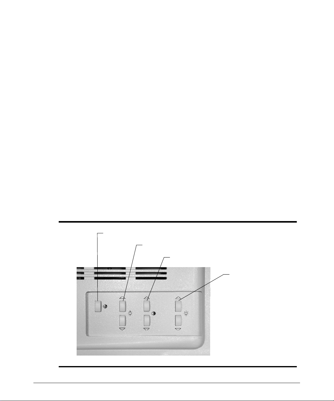
Monitor Module
The controls on the video monitor affect brightness, contrast, background color, and the
br ightnes s of t he lightbar ( F igur e 2-- 1) . When a c ontr ol is pr es s ed, an on- s c r een dis play
provides information about the relative level of brightness, contrast, background color, or
lightbar brightness (some monitors do not have an on-screen display for lightbar brightness). The on-screen display remains on until the timeout period ends, which is about
three seconds after the control is last pressed. To reset the monitor module control setting
to the default setting, press the increase and decrease controls simultaneously.
Before imaging with the system, wait about 20 minutes after turning the system on. The
system can be used, but the video monitor requires a warm-up period. This warm-upperiod is necessary to ensure consistent image quality.
Brightness adjusts the light output of the entire display.
Contrast adjusts the difference in light output between the light and dark parts
of the display.
Background Color selects the background color of the display.
Lightbar adjusts the brightness of the lightbar, which illuminates the control
panel.
CAUTION
HDI 5000 Reference Manual 4703-0027-03
Maintaining a very high display-contrast level can damage your screen. Do not
use high-contrast settings for an extended period of time.
2--1
Page 13
Controls
""""
""""
Monitor Adjustment
Optimal brightness and contrast settings can vary in different lighting conditions and even
from person to person. To minimize incorrect settings when there are multiple users, it is
best to keep the monitor set to the default values.
To display the current monitor control settings:
Press a background color, brightness, or contrast monitor control to display the current
control setting (Figure 2--1). Settings are displayed for approximately 2 seconds. The
lightbar brightness varies, but there is no on-screen display.
To adjust the monitor contrast and brightness to a default setting:
1. Simultaneously press the up and down contrast controls twice to set the monitor to the
factory default.
2. Simultaneously press the up and down brightness controls twice to set the monitor to
the factory default.
3. Simultaneously press the lightbar controls twice to set the monitor to the factory
default.
4. Press the background color control to select the background color onthe display.Color 1 is the factory default option.
2--2
5. Press the lightbar brightness control to adjust control panel illumination.
Background color selection
Lightbar brightness
Monitor contrast
Monitor brightness
Figure 2--1. Monitor Module Controls
HDI 5000 Reference Manual 4703-0027-03
Page 14

Controls
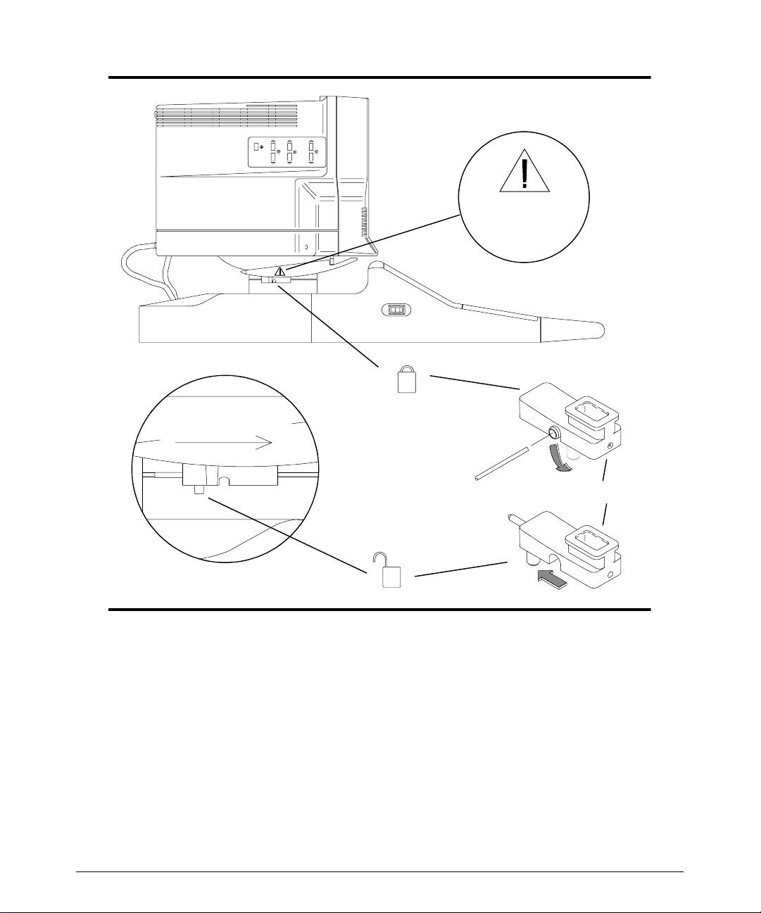
Monitor Latches
The monitor latch has been designed to avoid inadvertent unlatching when you place
items in the tray under the monitor. The handle requires a tool (small screwdriver or metal
rod) to unlatch it.
To unlatch the monitor, insert the tool in the center of the latch handle. Push down to rotate
the latch handle to the down position. Slide the handle toward the rear of the monitor to
unlock the latch. When the latch mechanism is unlocked, the latch handle hangs down
(Figure 2--2), and then the monitor can be removed from the system.
The monitor latch secures the monitor to the system. It is not a tilt/swivel latch. The latch
must remain in the locked position during normal system operation. Unlock the latch only
to remove the monitor from the system. The latch is shown in Figure 2--2.
WARNING
The monitor can fall off of the system if the latches are not locked.
HDI 5000 Reference Manual 4703-0027-03
2--3
Page 15
Controls
Monitor latch
safety label
Front of monitor
Use a metal rod or a screwdriver to rotate latch handle
to lock or unlock latch.
Latch assembly
Figure 2--2. Monitor Latches
2--4
HDI 5000 Reference Manual 4703-0027-03
Page 16
Controls
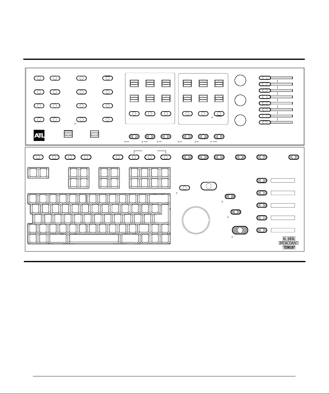
Control Module
See Figure 2--3.
MENU
2D / MM
3D / CINE
PWR
PHYSIO
DOPPLER
TRIGGERS
NET/DISK
COLOR
VOLUME
PROTOCOL PARAMS TIMERS
3D OPT
L/R INVERT
TOP/BOT
TDI
TOOLBAR
OUTPUT
REVIEW
END EXAM
DEL IMG
VCR CTRL
COLOR / DOPPLER
SCALE PRIORITY
BASELINE ANG COR
STEER
PULSED CW
OPTIMIZATION
FR RATE
FILTER ZONES
SV SIZE
0/60
"
INVERT
COLOR PWR IMG MMODE
HARMONICDUAL 2D/COLOR ADV MEASDEL MEASAREACALCS DISTANCE
COMPRESS
COMP IIMG
UPDATE
2D / M MO DE
SEC WIDTH
CURSOR
SELECT
DEPTHFOCUS
ZOOM
HD ZOOM
2D
RECORD
PRINT
2D GAIN
DOP GAI N
COL GAIN
FREEZE
HIGH Q
R
Figure 2--3. Control Module
0/60
"
Selects a Doppler angle correction value of 60 degrees to the right, 60 degrees to the left,
or 0 degr ees angle c or r ec t ion. See als o ANG COR .
2D
Starts 2D imaging. When 2D imaging is active, the indicator next to the control lights.
HDI 5000 Reference Manual 4703-0027-03
2--5
Page 17

Controls
2D GAIN
Adjusts the receiver gain for the 2D and M-mode image displays. Turn the control clockwise to increase the gain; turn the control counterclockwise to decrease the gain.
2D/COLOR OPTIMIZATION
Selects from among up to three different fundamental optimization settings for 2D, Color,
TDI, or Power imaging. Settings are dependent upon the active Tissue Specific preset.
2D/MM MENU
Displays a menu with 2D display parameters: Gray Maps (GMap), Chroma (gray-scale
colorization), Persistence, TIs/TIb, Biopsy Sel, 2D PRF, and Biopsy. The following M-
mode display parameters are also available from this menu: Speed and Display.
3D/CINE MENU
Displays a menu with Cineloop review parameters that control the Cineloop sequence,
change the speed of the Cineloop playback, select loop or sweep playback, and trim the
Cineloop sequence. The selections related to 3D imaging are as follows: Create 3D,
Views, Slice, and Cine. With the Advanced 3DI Position Sensor,a Resolution selection
is also available.
3D OPT
Press 3D OPT, during 3D imaging, to optimize the image for either general imaging, or
cardiology. The display indicates the system is optimized for 3D as follows: 2D Opt:Gen
3D or 2D Opt:Res 3D.
ADV MEAS
Displays the Meas Tools menu. The Meas Tools menu includes the following measure-
ment tools: Volume, Vol Method, Vol Flow, CO (Cardiac Output), Heart Rate, Time/
Slope, Calibrate, Set Region, Mean Tr (Mean Trace), Trace, and any optional
measurement tools that you have purchased. Optional tools include % Area Reduction (%
Area Red), % Diameter Reduction (%DiamRed), Hip Angle, and d:D Ratio.
ANG COR
Corrects for the anglebetween the beam axis andthedirection offlow. The cosine theta of
this angle is used in the Doppler equation to calculate the velocity of blood flow. The range
of Doppler angle correction is --70 degrees to +70 degrees in 2-degree increments. Push
the control up to rotate the flow direction cursor in the clockwise direction; push the control
down t o r otate t he flow dir ec t ion c ur s or in t he c ounter c loc k w is e dir ec tion. See als o 0/60
AREA
Displays a measurement cursor, initiates an area andcircumference measurement, ends
a measurement, and cycles through the available 2D or Doppler tracing methods.
.
""""
2--6
HDI 5000 Reference Manual 4703-0027-03
Page 18

Controls
BASELINE
Shifts the Doppler zero baseline for Doppler and Color imaging.
CALCS
Displays the calculations menu or measurement protocol that supports the active scanhead and clinical option.
COL GAIN
Adjusts the receiver gain for the ColororPower imaging display.Turn the controlclockwise
to increase the ColororPower gain; turn the control counterclockwise to decrease the Color or Power gain. Also adjusts the saturation of the VCR playback display.
COLOR MENU
Displays a menu with Color display parameters: Color Maps, Persistence, Post Pro-
cess, Sensitivity, Line Density, (L Density), Mode (velocity, variance, and power), Dynamic Motion Differentiation (DMD), Blending, Smooth, and Units.
COLOR
Turns Color imaging on and off. Displays the previously active imaging mode. WhenColor
imaging is active, the indicator next to the control lights.
COMP IMG
Activates SonoCT Real-time Compound Imaging. This control is active only for specific
scanheads that support this option. When active, an indicator next to the control lights.
COMPRESS
Changes the dynamic range of the 2D image. The dynamic rangeof the Power image can
be changed from the PWR menu.
CURSOR
During 2D imaging, displays a line of dots that corresponds to the M-line (for M-Mode) or
D-line and a depth cursor (for Doppler). The locations of the line and the depth cursor will
be used for data acquisition when you initiate a scrolling display. You can add the angle
correction cursor by pressing the ANG COR control.
CW
Press CW to turn on continuous-wave (CW) Doppler imaging. Press again to turn off CW
Doppler imaging and display the previously active imaging mode. When CW Doppler
imaging is active, the indicator next to the control lights.
DEL IMG
With the Image Management option, deletes the last image stored on the hard disk. With
the Digital Video Streaming (DVS) option, deletes the selected review image.
HDI 5000 Reference Manual 4703-0027-03
2--7
Page 19

Controls
DEL MEAS
Deletes the current measurement or a portion of the currently displayed circumference
trace.
DEPTH
Changes the image display depth.
DISTANCE
Activates the first cursor for a distance measurement.
DOP GAIN
Adjusts the receiver gain for the Doppler image display. Turn the control clockwise to increase the Doppler gain; turn the control counterclockwise to decrease the Doppler gain.
Also adjusts the tint of the VCR playback display.
DOPPLER MENU
Displays a menu with Doppler display parameters: 2D Update, Gray Maps, Chroma,
Scale Units, Speed, and Display.
DUAL
Provides access to the dualimage display. Dual images can be used for measurements in
a singleimage, if system requirements are met. Measurements are not allowed otherwise.
The UPDATE control is used to alternately activate the images.
2--8
END EXAM
With the Image Management option, press this control to end the current patient exam.
FILTER
Changes the value of the Doppler, Power, or Color wall filter.
FOCUS
Changes the depth of the focal zones. Pressing the control moves the focal zones up or
down to a shallower or deeper depth as reflected by the focal zone markers on the display.
FREEZE
Freezes all displayed images and captures the previously displayed frames for Cineloop
review,M-mode review, Doppler review,and3D creation. Displays the CAPTURE softkey,
which is used to capture loops for image management and review.
FR RATE OPTIMIZATION
In SonoCT Real-time Compound Imaging, changes the scanhead sweep between Sur-
vey and Target. Also changes the frame rate during 2D, Color, and Power imaging.
HDI 5000 Reference Manual 4703-0027-03
Page 20

Controls
HARMONIC OPTIMIZATION
Selects from among up to three different harmonic optimization settings for 2D THI, TDI
Harmonic, 2D CSI, or Flow CSI. The settings are dependent upon the active Tissue Specific preset.
HD ZOOM
During acquisition, provides optimal processing power to a selected region of interest. An
active (real-time) display is required for this feature.
HIGH Q
####
Turns on or turns off the peak Doppler trace display, and initiates the automatic calculation
and display of the specific values associated with the Doppler waveform.
INVERT
Inverts the pulsed- or continuous-wave Doppler display or Color display relative to the
baseline.
L/R INVERT
Selects the left or right orientation of the 2D image. An orientation marker adjacent to the
image display denotes the setting of this control.
MMODE
Displays M-mode imaging. Press a second time to return to the previous active imaging
mode. When M-mode imaging is active, the indicator next to the control lights.
NET/DISK MENU
Displays a menu with network and disk parameters that control formatting and ejecting an
optical disk, viewing the hard disk and optical disk exam directories, and getting disk
capacity and network status. With the DVS option, the patient directory is available from
the menu.
OUTPUT
Adjusts the ultrasound power output. Pressing this control up increases the acoustic output as reflected by anincrease in thethermal indexandmechanicalindexvalues;pressing
it down decreases the acoustic output as reflected by a decrease in these values.
PARAMS
With the DVS option, displays the Exam Parameters dialog box, from which you can
adjust capture format, ECG trigger, compression, and capture length for the active
acquisition protocol. During freeform capture, the Exam Parameters dialog box displays
the parameters for clip acquisition.
HDI 5000 Reference Manual 4703-0027-03
2--9
Page 21

Controls
PHYSIO MENU
Displays a menu with physio parameters that control the display of the ECG trace and the
physio channels A and B. You can then increase ordecrease gain, raise or lower the position of the physio traces, and display the TRIGGERS menu.
PRINT
Prints to the destination specified in the Peripherals and Image Management setups.
With the DVS option, stores images on the hard disk.
PRIORITY
Establishes the priority of display of gray-scale versus color information during Color and
Power imaging. The indicator on the gray scale graphically represents the gray level or
echo amplitude above which gray-scale information will be displayed and below which color information will be displayed.
PROTOCOL
With the DVS option, displays the Protocol Startdialog box from which you can select an
acquisition protocol.
PULSED
Turns onthe pulsed Doppler display.Press againto turn the pulsed Doppler display off and
display the previously active imaging mode. When pulsed wave Doppler is active, the indicator next to the control lights.
2--10
PWR IMG
Displays Power Motion imaging or Color Power Angio imaging, depending upon the clinical option selected. Press a second time to return to the previously active imaging mode.
When Power imaging is active, the indicator next to the control lights.
PWR MENU
Displays a menu with Power Motion imaging display parameters: Power Maps, Persis-
tence, PostProcess, Sensitivity, LDensity,DMD, Background, Display, and Dynamic Range. DMD is unavailable in cardiology clinical options.
RECORD
Initiates a recording of the video display on the system VCR. During recording, press this
control to pause the recording.
REVIEW
With the Image Management and the DVS options, allows review of stored images.
HDI 5000 Reference Manual 4703-0027-03
Page 22

Controls
SCALE
Changes the pulserepetition frequency and the range of the displayed velocity or frequency display range in Color, Power, and Doppler imaging. Automatically initiates high PRF,
when maximum velocity or frequency threshold is attained. Multiple sample volumes are
displayed.
SEC WIDTH
Changes the width of the 2D sector.
SELECT
Initiates an action or enablesacontrol. Alsoallows youto select a trackball option from the
trackball selection menu, which briefly appears above the image display.
STEER
Selects among three possible steering angles for linear array scanheads. The exact
angles are scanhead dependent.
SV SIZE
Changes the sample volume size. The available settings are as follows for all scanheads,
except the D2 TC pencil probe: 1.0, 1.5, 2.0, 2.5, 3.0, 3.5,4.05.0,7.5, 10.0, 12.5, and 15.0
mm. The D2 TC pencil probe has the following settings: 1.5, 2.0, 3.0, 5.0, 10.0, 15.0, and
25.0 mm.
TDI (Tissue Doppler Imaging)
With a compatible scanhead, in 2D Color, Color M-mode, and pulsed-wave Doppler, activates the TDI display.
TGC Slide Controls
Each slide control adjusts the receiver gain for the 2D and M-mode image displays at a
particular depth. When the slide controls are set in the center, a default curve is assigned
that gives a uniform gainthroughouttheimage display. The TGC curve on the screen does
not directly correlate to the TGC slide control positions. Color,Doppler, andPowerimaging
are not affected by the TGC slide controls; these modes assume a flat TGC curve.
TIMERS
With the DVS option, controls three timers used in freeform capture and acquisition protocols.
TOOLBAR
With the DVS option, displays the image-review toolbar. Press a second time to remove
the image review toolbar.
HDI 5000 Reference Manual 4703-0027-03
2--11
Page 23

Controls
TOP/BOT
Changes the top and bottom orientation of the image display. An orientation marker adjacent to the image display denotes the setting of this control.
Trackball
The trackball is used to movedisplayelementsofalltypes. Press SELECT to cycle among
the available trackball options. The options appear immediately above the 2D image display.
TRIGGERS MENU
Displaysthe Triggersmenu. The Triggers menu contains selections for changingthetim-
ing of image update relative to cardiac cycles.
UPDATE
In ECG-triggered imaging, activates ECG update based on thetriggersyou have selected.
In dual imaging, switches between the two images: if the dual display is active, pressing
UPDATEtoggles between activating the left and right images; if the dual display is frozen,
pressing UPDATE switches between the display of the Cineloop sequence related to each
image. In duplex, UPDATE activates the 2D image or the scrolling display. In simultaneous, UPDATE switches between simultaneous and duplex update.
VCR CTRL
Allows the VCR to be operated from the system control panel. Displays PLAY, PAUSE,
STOP, FF, and REWIND softkeys.
VOLUME
Push the controlupto increase the audiovolume from the system speakers. Push the control down to decrease the audio volume from the system speakers.
ZONES
Selects the number of focal zones and the distance between them. The maximum number
is five. The range and number supported depends upon the type of scanhead being used.
ZOOM
Magnifies the image in freeze or real-time. There are eight settings. The trackball can be
used to pan the magnified image to see areas that are not displayed.
2--12
HDI 5000 Reference Manual 4703-0027-03
Page 24
Controls
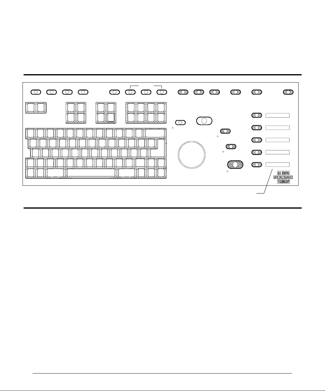
Softkeys
There are five softkeys located on the right side of the control panel. The softkeys that
appear are dependent upon system operation. For example, when you press VCR CTRL,
the VCR softkeys appear.
PROTOCOL PARAMS TIMERS
TOOLBAR
OPTIMIZATION
HARMONICDUAL 2D/COLOR ADV MEASDELMEASAREACALCS DISTANCE
FR RATE
HIGH Q
R
UPDATE
SELECT
RECORD
PRINT
3D CALIB
FREEZE
Softkeys
Figure 2--4. Softkey Controls
2D CINE
Plays back the 2D Cineloop review.
3D CALIB
Displaysthe3D Calib menu, whichincludes selections for resolution, trigger delay, trigger
interval,frames, and frameinterval, memory used, delay,even, systole, andR-R.With the
Advanced 3DI option, initiates calibrated 3D acquisition.
3D UNCAL
Starts and stops Cineloop acquisition for uncalibrated 3D image rendering.
ACCEPT
Accepts image clips for storage to the hard disk.
CANCEL
In 3D imaging, closes the 3D Calib menu, aborts the current 3D acquisition, and returns to
2D imaging. With theDVSoption,stopsimagecapture, deletes image frames captured for
the current view, and resets the softkeys.
HDI 5000 Reference Manual 4703-0027-03
2--13
Page 25

Controls
CAPTURE
Initiates the acquisition of a clip.
DONE
With the DVS option, stops image capture.
END
With the DVS option, ends an acquisition protocol, the image collection for the stage, and
advances to the next stage of an acquisition protocol.
FF
A VCR control used to fast f orward the VCR.
LABEL VL
Used to label and store a 3D image sequence using a Label Volume form.
PAUSE
Temporarily freezes acquisition. Enables the CANCEL and RESUME softkeys. A VCR
control used to pause the VCR.
PLAY
A VCR control used to play the VCR.
REJECT
Deletes a selected clip and returns to real-time imaging.
RESUME
Resumes 3D acquisition. With the DVS option, resumes image capture.
REWIND
A VCR control used to rewind the VCR.
START
Closes the 3D Calib menu and begins acquisition. Enables the CANCEL and PAUSE
softkeys.
STOP
A VCR control used to stop the VCR.
STORE
Stores selected images to the hard drive. Unselected images are discarded.
2--14
HDI 5000 Reference Manual 4703-0027-03
Page 26

Controls
STORE VL
Stores anacquired 3Dimage volumetothe system harddisk. Also initiates datatransfer to
the workstation or the magneto optical disk, depending on your system’s network setups.
VIEW >
Advances to the next logical view in a stage of an acquisition protocol.
VIEW <
Returns to the previous logical view in a stage of an acquisition protcol.
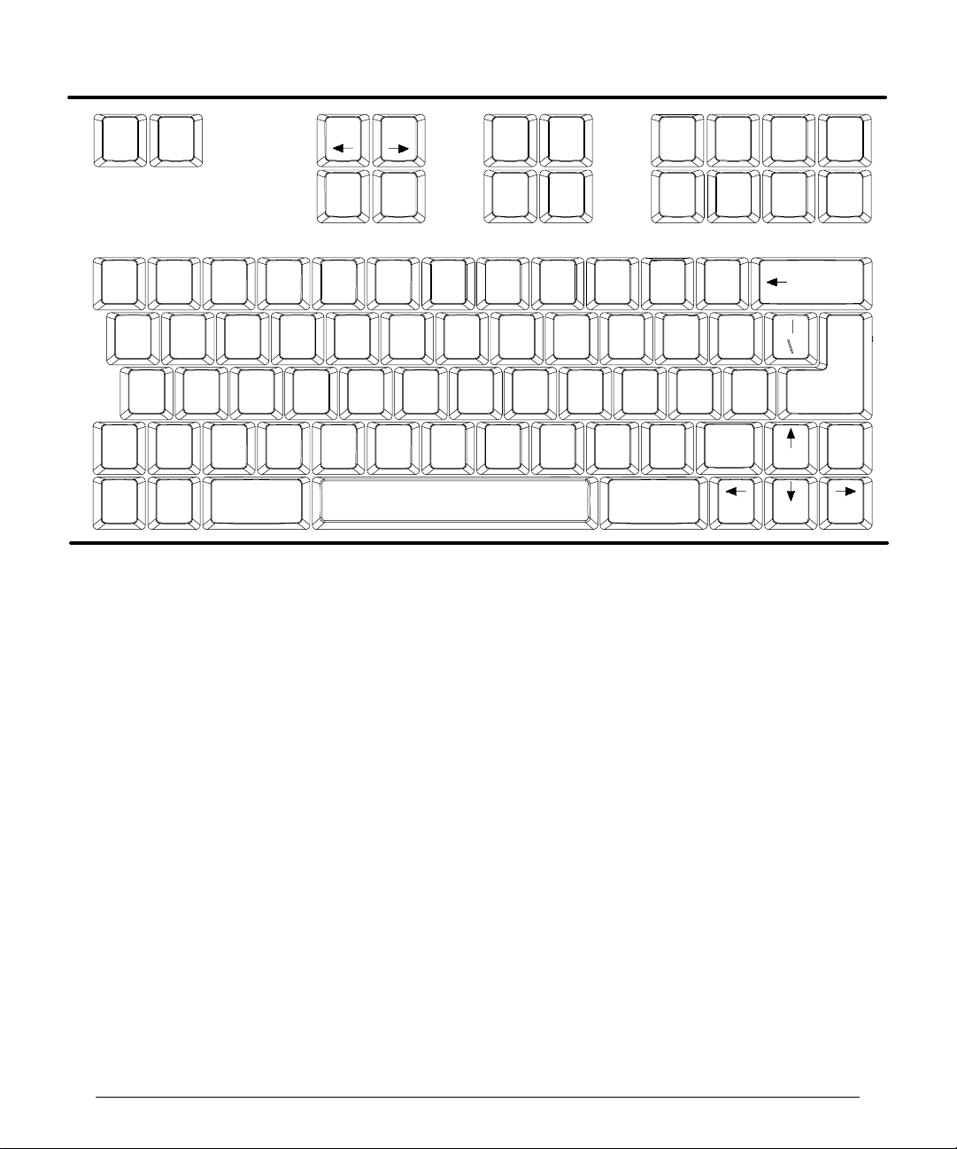
Keyboard
The keyboard contains special function keys, alphanumeric keys, annotation keys, and
s uper k ey s ( F igur e 2-- 5) . With t he s pec ial f unc tion k ey s , y ou c an per for m s pec ific func tions, such as choosing a scanhead or changing setups. The alphanumeric keys areused
with the annotation keys to enter text. The superkeys are used with the Superkey (there
are two, for convenience) to more quickly adjust various image display processing or format characteristics.
The superkeys, labeled with small text below the characters, allow quicker adjustments
than if you usethe corresponding MENUcontrols. Using the superkeys results inanimmediate change to the setting. A five-second prompt appears above the image display to indicate the new setting. The image display and the image information is slso updated to
reflect the new setting.
On a menu, an underlined letter is a keyboard equivalent. When you press a keyboard
equivalent, the result is the same as selecting the menu item.
The following paragraphs describe the functions of each of the keys on the keyboard that
have special functions. Alphanumeric keys that do not have special functions are simply
used for text entry, and they are not listed or explained in the following.
HDI 5000 Reference Manual 4703-0027-03
2--15
Page 27
Controls
Scan
head
!
Shift
Quick
Save
Q
2D M aps
A
R
Fr Rate
F
Mean Tr
Page
Setups
%
5
Page
Report
^
6
T
Biopsy
G
Tr Dir
VBCZX
CDispCPers Pwr Bg
&*
7
Y
H
Dop
Chroma
U
Graphics
NM
2D Ref
J
Simult
Text
Text Text
C D
8
I
Print
Suspend
Protocol
TI
Text
BA
(
)
9
P
O
Field
A/BLocal
LK
Counter
<
>?
,
Superkey
Video
Title Arrow
Erase
Line
_
--0
:
;
/.
Erase
Arrow
Screen
+
=
}{
][
”
Micro
phone
’
Shift
Playback
Dop
Maps
Patient
Data
@
21
Chroma
CMaps1
TI
Help
2D
Disp
Format
#
3
EW
2D Pers
DS
Speed
Superkey
$
4
Figure 2--5. Keyboard
$%&'
Press these keys to move the annotation cursor in the direction the arrow points. Press
Shift and an arrow key to annotate the image display at the cursor location with an arrow
that points in the direction of the arrow key. The trackball can then be used to position the
arrow on the display . Additional arrows may be displayed by pressing shift and this key.
Erase
Backspace
Return
Cine
Set
TextHome
Erase
Text
Body
Marker
SH PosHome
2--16
1,2,3,4
Press the Superkeyand one of these keys to select a scanhead, if the scanhead is compatible with the currently selected Tissue Specific preset. The numbers correspond to the
scanhead receptacles: 1 corresponds to the scanhead receptacle on the left, 2 the middle,
3 the right, and 4 is the pencil probe receptacle. If the scanhead is not compatible with the
currently-selected Tissue Specific preset, then the system will prompt you to select a
scanhead and a Tissue Specific preset.
2D Chroma
Press the Superkey and this key to change the 2D imaging Chroma map.
2D Maps
Press the Superkey and this key to change the 2D gray map.
HDI 5000 Reference Manual 4703-0027-03
Page 28

Controls
2D Pers
Press the Superkey and this key to change the 2D persistence setting. You cannot
change persistence, dynamic range, or frame rate when the system is in freeze.
2D PRF
Press Superkey and this key to cyclethe frame rate inall modes through Low, Med, and
High values. 2D PRFis equivalent to the 2D PRF selection on the 2D/MMode menu. Se-
lecting an alternate 2D PRF setting may reduce or eliminate reverberation artifact.
2D Ref
Not functional at this time.
Arrow
Displays an arrow on the display. Use the trackball to move the arrow. Press the SELECT
control to anchor the arrow. Press Arrow again to display another arrow.
Biopsy
Press the Superkeyand this key to turn on or turn off the display of the biopsy guide line.
Backspace
Erases the character to the left of the cursor.
Body Marker
Selects a body marker. Once the body marker is displayed, you can use the trackball to
move the body marker. The available body markers are dependent upon the Tissue Specific preset.
HDI 5000 Reference Manual 4703-0027-03
2--17
Page 29

Controls
CDisp
Press the Superkey and this key to turn on or off the display of color on the image.
Cine Playback
Press the Superkey and this key to alternate between play and pause in Cineloop review.
CMaps 1
Press the Superkey and this key to change the color map.
Counter
Press the Superkey and this key to display a dialog box that can be used to set the VCR
frame counter, search the tape for a specific frame, or cancel the operation. The frame
counter is turned on or off in Setups.
CPers
Press the Superkey and this key to change the 2D Color or Power Motion persistence
level. Ensure that the system is not in freeze; you cannot change persistence, dynamic
range, or frame rate when the system is in freeze.
Disp Format
Press the Superkey and this key to change the size of the scrolling display.
2--18
Dop Chroma
Press the Superkey and this key to change the Doppler Chroma map.
Dop Maps
Press the Superkeyandthiskeyto change the gray map that isusedfor the Doppler imaging display.
Erase Arrow
Erases an arrow from the display.
Erase Line
Erases a line of text. The cursor must be located on the lineof text that youwant to erase.
Erase Screen
Erases text, title, body markers, arrows, and scanhead position markers from the display.
Erase Text
Erases user-entered text from the display.
HDI 5000 Reference Manual 4703-0027-03
Page 30

Controls
Field A/B
Press the Superkey and this key to select among three settings that vary the clarity of the
VCR freeze-frame image. A VCR freeze-frame image is composed of two video fields.
Field A/B cycles among field A, field B, and the video frame. After pressing the FREEZE
control, you must press STOP on the VCR (or the STOP softkey) touse the Field A/B key
to select the A or B fields or frame.
Graphics
Press the Superkey and this key temporarily removes the graphics from the captured
review images.
Home
P os ition s t he c ur s or at the home pos ition. See Set H o m e .
MeanTr
Press the Superkeyand this key to turn on or off the display of the High Q mean trace on
the Doppler display.
Microphone
Turns the microphone on or off.
Page
''''
Pages through the review images and the patient report.
Page
%
Pages through the review images and the patient report.
Patient Data
Displays or removes the Patient Data Entry form.
Print Local
Press the Superkey and this key to print with an internal printer or store an image. The
Use Print ButtonTo setup in the Image Management setups determines the function of
the Print Local key. With the DVS option, it initiates a print with an internal printer.
Pwr Bg
Press the Superkey and this key to turn on or off the background of the Power imaging
overlay.
Quick Save
Saves the current system settings as a user-defined preset for the active scanhead and
clinical option.
HDI 5000 Reference Manual 4703-0027-03
2--19
Page 31

Controls
Report
Displays or removes the patient report.
Return
Moves the cursor to the next line on the video display.
Scanhead
Displays the Scanhead display.
Set Home
Press the Superkey and this key to establish a home position for the currently active annotation cursor. The cursor will appear in this location each subsequent time that it is activated using the Text, Text A--D, Title,orBody Marker keys. Press Shift and this key to
annotate the image display at the cursor location with an arrow that points down.
Setups
Displays the Directory of Setup Options, which contains several categories of setups
based on your system configuration: Display, Peripherals, Image Management, An-
notation, Calculations, Physio, Acquisition Parameters, Measurements, and Tissue Specific Presets. There are also selections for Temporary Options and
Diagnostics.
2--20
Shift
Press this key andanother key on the keyboard to display the upper or lower case character or the alternate character assigned to that key.
SH Pos
When the annotation cursor is displayed, press this key to move the annotation cursor to
the right. When the body marker is displayed, press the Superkey andthe SHPos key to
display the scanhead position marker; use the trackball to change the orientation of the
scanhead position marker. Press again to remove the scanhead position marker. Press
Shift and this key to annotate the image display at the cursor location with an arrow that
points to the right.
Simult
Press the Superkey and this key to start and stop simultaneous mode.
Spacebar
Moves the cursor to the right.
Speed
Press the Superkey and this key to change the scrolling sweep speed.
HDI 5000 Reference Manual 4703-0027-03
Page 32

Controls
Superkey
Press this key and another key to activate a function or change a display parameter. The
keys that are used with the Superkey are distributed throughout the keyboard.
Suspend Protocol
With the DVS option, press the Superkey and this key to suspend the active acquisition
protocol. Press it a second time to resume the acquisition protocol.
Text A, B, C, D
Press these keys to display a pre-defined, application-specific annotation. Each of these
keys can have a list of pre- or user-defined annotation assigned to it, which you can cycle
through and display.
Text
Press this key to enable text-entry onto the image display. Initially, the cursor appears in
the left side of the display in the text home position.
Title
Press this key to enter a title onto the image display. The cursor appears in the upper left
corner in the title home position, and two lines of text can be entered in this area.
TI Help
Press this key to display a help screen that briefly describes the TI and MI values.
TI
Press the Superkey and this key to cycle between TIs and TIb. For more information
about the output display, press the TI Help key or refer to the “Safety” section of the
heads and Safety
manual.
Scan-
Tr Dir
Press the Superkeyandthiskeyto select the trace direction for High Q Automatic Doppler
measurement, above, below, or above and below the baseline.
Video
Press the Superkeyand this key to change thevideosourcefor the system video monitor.
Pressing this key cycles throughthevideosources, which are determined by your Periph-
erals setups.
HDI 5000 Reference Manual 4703-0027-03
2--21
Page 33

Controls
Main Chassis
The controls on the main chassis are the circuit breaker and the ON/STANDBY switch
(Figure 2--6).
Circuit Breaker
Located on the back of the system, the circuit breaker is used to switch power to the system on (standby) or off.
ON/STANDBY
Located onthe left side of the system, the ON/STANDBYswitch turns the system to on or
standby.
STANDBY
Circuit breaker
ON/STANDBY switch
ON
Figure 2--6. Main Chassis Controls
2--22
HDI 5000 Reference Manual 4703-0027-03
Page 34

Setups
Introduction
Setups are system parameters. There are three types of setups: system setups, Tissue
Specific preset setups, and software setups. Changing any setup takes effect immediately. System setups aresaved through a power cycle. TissueSpecific preset setups are only
in effectuntilthe current Tissue Specific preset is changed ora power cycle occurs. Tissue
Specific preset setups can be saved as part ofauser-defined Tissue Specific preset using
the Quick Save key. Software setups allow an ATL Ultrasound representative to install a
system feature temporarily for demonstration purposes.
Clinical Options and Tissue Specific Presets
The clinical options are broad areas ofmedical study. On the Scanhead display, there is a
list of clinical options. Additionally, the clinical options are associated with one or more Tiss ue Spec ific pr es et s ( F igur e 3-- 1) . F or ex ample: within the s mall par ts c linic al option, the
Tissue Specific presets are thyroid, testicle, breast, and superficial. If you select the small
parts clinical option, these Tissue Specific presets will be displayed onthe Scanhead display for your selection. An appropriate measurement protocol is also available, from the
CALCS control, based on the clinical option selected.
You specify how the system will be set up for operation by selecting a clinical option and a
Tissue Specific preset. The more specific you are about your intended use of the system,
the more you can take advantage of Tissue Specific imaging.
HDI 5000 Reference Manual 4703-0027-03
3--1
Page 35

Setups
Scanheads
Clinical options
Figure 3--1. Clinical Options and Tissue Specific Presets: Scanhead Display
Tissue Specific presets
Scanheads and Tissue Specific Presets
You optimize the system for imaging when you select a Tissue Specific preset. You can
also create your own Tissue Specific imaging presets. The Quick Save key provides this
c apability ( F igur e 3-- 2) . You c r eate a pr es et name f or y our optimiz ed pr es et. O nc e y ou as sociate the scanhead with the current system settings by saving them, from this point on,
that scanhead will be associated with an optimized preset, and the preset name appears
on the Scanhead display. If you do not enter a name, and then save the current system
settings, a system default name will be used to identify the Tissue Specific preset, for example: Custom X.
Once you have saved apreset in this way, each time that you press the Scanhead key,the
list of Tissue Specific presets for a scanhead type will include your custom preset. You can
choose presets, save presets to a disk, retrieve presets from a disk, select a power-up
clinical option, and transfer presets between systems.
3--2
HDI 5000 Reference Manual 4703-0027-03
Page 36

Setups
Figure 3--2. Quick Save for Creating a Preset
HDI 5000 Reference Manual 4703-0027-03
3--3
Page 37

Setups
Directory of Setup Options
The Setups key displays the Directory of Setup Options (Figure 3--3), which lists sys-
tem setups, Tissue Specific presetsetups, and software setups. The directory is based on
your system configuration and will vary accordingly. All of the setups are explained in the
glossary.
When you select from the directory, a list of the setups for that option appears on the
screen. You can select the values for the setups. The Diagnostics, Close, and Arrow
(left and right)buttonsatthe bottom ofthe display allow you to usethe systemdiagnostics,
close the directory, or move through the directory.
Changes to setups are saved when power is switched off, or by entering new patient data,
except for the TissueSpecificpreset setups, which areresetwhentheTissue Specific preset is changed.
3--4
Figure 3--3. Directory of Setups Options (Example)
HDI 5000 Reference Manual 4703-0027-03
Page 38

Setups
System Setups
System setups comprise the Display, Peripherals, Image Management, Annotation,
Calculations, Physio, and Acquisition Parameters setups. Depending upon your sys-
tem configuration, you will have all or some of these available in your directory.
Display Setups
Display setups cover a range of system parameters related to the screen header, display,
and measurements (Figure 3--4).
Institution field
Date field
Time field
Figure 3--4. Display Setups
HDI 5000 Reference Manual 4703-0027-03
3--5
Page 39

Setups
Peripherals Setups
Peripherals setups are related to the selection and setup of internal or external printing or
recording devices for use with the system. You can also turn the speakers and the VCR
frame counter on or off (Figure 3--5).
3--6
Figure 3--5. Peripherals Setups
HDI 5000 Reference Manual 4703-0027-03
Page 40

Setups
Image Management Setups
Image Management setups are related totheselection and setup of the system andImage
Management devices for Worklist, DiskLink, NetLink, WebLink, and DigitialVideoStreaming operation.Dependingupon your system configuration, the appropriate directoryofsetup options is displayed (Figure 3--6).
Figure 3--6. Directory of Image Management Setup Options (Example)
HDI 5000 Reference Manual 4703-0027-03
3--7
Page 41

Setups
Annotation Setups
Annotation setups provide the capability to customize the Text A, B, C, and D keys. Fora
Tissue Specific orcustom preset, you cancreatealist of specific terms that you mightwant
to use during an exam (Figure 3--7) and assign them to one of the four Text keys. Once
created in Setups, these terms are available during an exam by pressing the Text key to
which you assigned them.
3--8
Figure 3--7. Annotation Setups
HDI 5000 Reference Manual 4703-0027-03
Page 42

Setups
Calculations Setups
Calculations setups include Analysis and General Cardiology setups (Figure 3--8).
Figure 3--8. Directory of Calculations Setup Options Display
Analysis
Each measurement, calculation, table, and equation has characteristics that can be
viewed or modified by using system setups. The Calculations: Analysis display is the
main menu for configuring analysis and is used to view the current configuration
( F igur e 3-- 9) . T he left s ide, labeled Current Configurat ion , has the lis t o f p r o toc o ls , c alculations, and measurements that you can select for viewing. The selections on the Cal-
culations: Analysis display have grayed--out labels when they are not available. The
selection you make under Current Configuration determines the selections that are
av ailable. Compar e t he dis play s in F igur e 3-- 9:
HDI 5000 Reference Manual 4703-0027-03
3--9
Page 43

Setups
3--10
Figure 3--9. Current Configuration
In the example with Fetal Biometry highlighted, there isan expanded list of measure-
!
ments under the protocol Fetal Biometry.
In the example with BPD highlighted, BPD is a measurement option in the protocol
!
Fetal Biometry. With BPD highlighted, the selections Advanced, Views, and Table
are all selectable. For example, if Table is selected, a tablecan beviewed, edited,and
configured. Other Current Configuration selections can make a different set of
selections appear.
HDI 5000 Reference Manual 4703-0027-03
Page 44

Setups
Calculation Analysis Display Conventions
Icons that appear on the Current Configuration list are as follows:
!
!
!
!
To view an analysis configuration:
""""
1. Press the Setups key. The Directory of Setup Options appears.
2. Select Calculations.TheDirectory of Calculations Setup Options appears.
3. Selec t An alysis .The Calculat ions: Analysis dis play appear s ( F igur e 3-- 9) . T he
4. Highlight one of the options from the list underCurrentConfiguration. (BPDis high-
5. Select View.
indicates a measurement.
indicates a calculation, which may have a table.
indicates a protocol
indicates a protocol opened to display its measurements.
analysis options are listed under Current Configuration.
lighted in F igur e 3-- 10.)
-- If a measurement option is highlighted, the View Measurement dialog box
appear s ( F igur e 3-- 10) .
-- If a calculation option is highlighted, the View Calculation dialog box appears
(Figure 3--11).
Note
HDI 5000 Reference Manual 4703-0027-03
When a protected calculation or other element is selected, the
tions ar e gr ay ed out to pr ev ent c or r uption of s tandar diz ed c alc ulations and meas ur ements supplied with the analysis enhancements.
Save
and
Delete
selec-
3--11
Page 45

Setups
3--12
Figure 3--10. View Measurement
HDI 5000 Reference Manual 4703-0027-03
Page 46

Setups
Calculations Analysis Configuration Display
Configuring Calcs protocols is accomplished in the Calculations: Analysis display in
system setups, which has a set of displays used to configure your system for automatic
analysis and reporting. When configured, each study type or an individual patient exam
has its analysis tools ready when you press the CALCS control.
The Calculations: Analysis display is composed of a configuration list, ameasurements
list, a set of control selections, a drop--down clinical options list, andseveral hidden dialog
boxes that appear as you need them. The hidden dialog boxes are used to modify calculations, measurements, and protocols.
To access configuration displays and selections:
""""
1. Press the Setups key. The Directory of Setup Options appears.
2. Select Calculations.ADirectory of Calculations Setup Options appears
( F igur e 3-- 12) .
HDI 5000 Reference Manual 4703-0027-03
Figure 3--11. View Calculation
3--13
Page 47

Setups
Figure 3--12. Calculations: Analysis Display
3--14
3. Select Analysis.TheCalculations: Analysis display appears (Figure 3--12). From
this display you can view a list of measurements, calculations, and protocols under
Current Configuration.
4. Use the drop-down clinical options list to view the clinical options.
5. Select a clinical option. The clinical option appears in the text field. A new list of protocols related to your selection appears under Current Configuration.
6. Double-select an item on the list under CurrentConfiguration. Thelist expands, and
new selections appear based on your selection.
7. Highlight a measurement. More selections appear.
8. Select Advanced to display the Global Measurement List, which contains meas ur ements t hat c an be added to the lis t of meas ur ements f or a pr otoc ol ( F igur e 3-- 13) .
HDI 5000 Reference Manual 4703-0027-03
Page 48

Setups
Calculation
Protocol
Measurement
Figure 3--13. Calculations: Analysis Display Selections
Configuration list
Drop-down list
Configuration selections
Calculations Analysis Selections
Selections on the Calculations: Analysisdisplay are available asneeded to accomplish
a configuration task. They are available for selection when visible and not grayed out. To
assist indescribing theselections, the FetalBiometryprotocol isillustrated here because
it has the most selections of any protocol. The selections are described as follows
( F igur e 3-- 13) :
Under Current Configuration is a list of measurements, calculations, and protocols.
!
The Calculations: Analysis display selections change as you make selections on
the Current Configurationlist.
-- Double-select a protocol to expand the Current Configuration list, gain access
to configuration selections, and to view measurements and calculations.
-- Select a calculation foraccess to Edit and Table selections,toedita calculation or
table.
-- Select a measurement to edit or delete a measurement.
-- Items not grayed out in the configuration list display on Calcs menus when you
press CALCS during exam.
HDI 5000 Reference Manual 4703-0027-03
3--15
Page 49

Setups
Selecting the drop-down list displays a list of clinical options. When a clinical option is
!
highlighted on the list, it appears in the text field. The Current Configuration list
changes to include protocols, measurements, and calculations available with the chosen clinical option.
You can copy items from the Global Measurement List intoprotocols underCurrent
!
Configuration. Highlight a protocol and select Advanced to display the Global Measurement List.
Configuration selections include the following:
!
-- Sel ect Copyto copy a global measurement to a selected protocol. When copying
is completed, Cancel Copy changes to Disable/Enable.
-- Sel ect Cancel Copy to cancel a copy selection. Cancel Copy only appears im-
mediately after Copy is selected, during the data transfer time.
-- Sel ect Disable/Enable to turn a measurement or calculation off or on in a proto-
col. When you disable an entry, it changes color on the Current Configuration
list and is removed from the Calcs protocol list.
-- Sel ect New Meas to create a measurement that is not in a protocol and is not
available in the global measurement list. When a new measurement is created, it
appears on the expanded protocol list when the protocol is double-selected.
-- Sel ect New Calc to create a new calculation or equation.
-- Sel ect Edit to modify a measurement or calculation. Edit is grayed out unless a
measurement or calculation in the Current Configuration list is highlighted.
-- Sel ect Table to modify or add a table or new equation. This selection is grayed out
until an item that uses a table or equation is highlighted on the Current Confi-
guration list.
3--16
HDI 5000 Reference Manual 4703-0027-03
Page 50

Setups
""""
Configuring CALCS
To copy a measurement or a calculation to a protocol:
1. Access the Calculations: Analysis display as described in “To access configuration
displays and selections.”
2. Highlight or double-select the protocol to which you want to copy the measurement.
3. Select Advanced.TheGlobal Measurement List appears.
4. On the Global Measurement List, highlight the measurement you want to copy.
Copy and Cancel Copy selections appear (Figure 3--14).
5. Select Copy.TheCancel Copy selection remains while the system copies the mea-
surement to the protocol. When the copyingiscomplete, themeasurement appears at
the bottom of the protocol’s measurement list, and Cancel Copy changes to Enable/
Disable.
Figure 3--14. Copy and Cancel Copy Selections
To delete a measurement or calculation from a protocol:
""""
Some measurements andcalculations are protected from being deleted. Delete is grayed
out for entries that are protected.
1. Access the Calculations: Analysis display as described in “To access configuration
displays and selections.”
HDI 5000 Reference Manual 4703-0027-03
3--17
Page 51

Setups
2. Double-select the desired protocol folder to expand the protocol list to view the measurement level. Example: The Fetal Biometry folder expands to display several measurements and calculations that are part of the protocol labeled Fetal Biometry
(Figure 3--15).
3. Highlight the item you want to delete.
4. Select Edit.TheEdit Measurement or Edit Calculation dialog box appears
(Figure 3--15).
5. Select Delete. A message appears, “Deleting data. Please wait...,” and the highlighted item is deleted from the list. The display returns to the Calculations Analysis
display.
3--18
Figure 3--15. Deleting a Measurement
To disable a measurement from displaying on the protocol list:
""""
1. Access the Calculat ions: Analysis dis play as des c r ibed in “ To ac c es s c onfigur ation
displays and selections.”
2. Highlight a measurement or a calculation on the Current Configuration list.
HDI 5000 Reference Manual 4703-0027-03
Page 52

Setups
""""
3. Select Disable. The selected measurement or calculation is grayed out and does not
appear on the protocol list during an exam. (To enable a measurement or calculation
that has been dis abled, r epeat s t ep 2, and s elec t En ab le .)
To edit a calculation or measurement:
1. Access the Calculat ions: Analysis dis play as des c r ibed in “ To ac c es s c onfigur ation
displays and selections.”
2. Highlight a protocol folder. The Current Configuration list expands to display measurements and calculations.
3. Highlight the item you wish to edit.
4. Select Edit.AnEdit Measurement or Edit Calculation dialog box is displayed
(Figure 3--16).
5. Modify the data fields and selections as needed in the dialog box.
6. Select Save. A message, “Saving data. Please wait...” appears and then the Calcula-
tions: Analysis display appears. All modifications are saved.
Figure 3--16. Editing a Measurement
HDI 5000 Reference Manual 4703-0027-03
3--19
Page 53

Setups
""""
To define a new measurement:
1. Access the Calculat ions: Analysis dis play as des c r ibed in “ To ac c es s c onfigur ation
displays and selections.”
2. Highlight the protocol to which you want to add your defined measurement.
3. Select New Meas.ANew Measurement dialog box appears (Figure 3--17).
Drop-down lists
Note
3--20
Figure 3--17. Defining a New Measurement
4. Type in a new abbreviation and report label.
The labels must be unique to the new measurement; they cannot duplicate labels used
in protocols and global measurements.
5. Select the Meas. Type drop-down list. A measurement list with a scroll bar is displayed.
6. Select the desired measurement. Your selection appears in the Meas. Type text field.
7. For Units and Precision select the drop-down lists.
8. Select the desired Units and Precision settings.
HDI 5000 Reference Manual 4703-0027-03
Page 54

Setups
""""
9. Set the other settings in the dialog box to your preference.
-- Show in Sidebar refers to the Calcs menu that you see after pressing CALCS
during imaging. If you want tosee your new measurement in the Calcs menu, you
must select Show in Sidebar.
-- Show in Report must beselected if you want your new measurement tobe in the
patient report.
-- Answer the question, “Should the measurement have an OB Age table?”
10. Select Save. The measurement is saved and appears in the Current Configuration
list.
To define a new calculation:
1. Access the Calculat ions: Analysis dis play as des c r ibed in “ To ac c es s c onfigur ation
displays and selections.”
2. Selec t New C alc .ANew C alcu lat io n dialog box appear s ( F igur e 3-- 18) .
3. Type in the Abbreviation and Report Label.
Note
The labels must be unique to the new calculation; they cannot duplicate labels used in
protocols and global measurements.
4. For Units and Precision select the drop-down lists.
5. Select the desired Units and Precision settings.
6. Set the other settings in the dialog box.
-- Show in Sidebar refers to the Calcs menu that you see after pressing CALCS
during imaging. If you want tosee your new measurement in the Calcs menu, you
must select Show in Sidebar.
-- Show in Report must beselected if you want your new measurement tobe in the
patient report.
HDI 5000 Reference Manual 4703-0027-03
3--21
Page 55

Setups
Drop-down lists
Figure 3--18. Defining a New Calculation
7. Move the cursor to the place in the equation field where you want to insert abbreviations or characters. Press SELECT. A flashing text cursor appears at the insertion
point in the equation field.
8. Combine typed characters and mathematical operators and the required measurement abbreviations to create the new equation:
-- For mathematical operators, use the conventions listed on the display.
-- To enter abbreviations, select the drop-down list to view the Meas. Abbreviation
list. Highlight the desired abbreviation. Press SELECT.Your choice appears inthe
Meas. Abbreviation field. Select Add. The abbreviation appears at the insertion
point.
9. When the equation is correctly entered, select Save. The dialog box disappears, and
the display returns to the Calculations: Analysis. The new calculation is addedto the
bottom of t he lis t of meas ur ements f or the s elec ted pr otoc ol ( F igur e 3-- 19) .
3--22
HDI 5000 Reference Manual 4703-0027-03
Page 56

Setups
Figure 3--19. New Calculation
OB Tables and Equations
Analysis can be configured with customized or standard tables and equations.
To configure fetal growth and fetal weight tables and equations:
""""
This procedure chooses oneexample of a setup to describe the use of display selections.
The example adds a table to a patient study on estimated fetal weight (EFW) and usesthe
Hadlock1 table and equation.
1. Access the Calculat ions: Analysis dis play as des c r ibed in “ To ac c es s c onfigur ation
displays and selections.”
2. Select OB from the drop-down list under Current Configuration.
3. From the Current Configuration list, highlight a measurement that requires a table.
EF W is highlighted in this ex ample ( F igur e 3-- 20) .
HDI 5000 Reference Manual 4703-0027-03
3--23
Page 57

Setups
3--24
Figure 3--20. EFW Table/Equation Setup
4. Select Table.TheTable/Equation Setups dialog box appears.
5. Across the top of the Table/Equation Setupsdialog box are selections of FetalAge,
Fetal Growth, Fetal Weight, and Percentile. Select either Fetal Growth or Fetal
Weight.
6. At this point you have several options:
-- Select a table or No Table from the displayed list: Highlight a table or No Table
and select Select Table. The text field to the right of Current Selection displays
your selection, and the new table is used in the OB report.
-- Select a user-table and edit its equation: Highlight a table from the list and select
Edit/V iew. An equation dialog box appear s ( F igur e 3-- 21) . Edit t he equation as
des c r ibed in s t eps 4-- 8 of “ To define a new c alc ulation . ”
HDI 5000 Reference Manual 4703-0027-03
Page 58

Setups
Figure 3--21. Editing or Defining a New Equation
-- Define a new table: Select New Table. A table dialog box appears with a table
template and selections used for designing a table. Select Save to save the new
table.
-- Define a new equation: Select New Equation. A new equation dialog box
appears (Figure 3--21) with fields and selections used for defining an equation.
Select Save to save the new equation.
-- Delete an item from the list: Highlight the item and select Delete. A dialog box
appears with the message, “Deleting a current selected table will default the current table selection to ’NoTable’.” Select Continue to delete the entry. When protected items are selected, a message appears, “This table name cannot be
deleted.” Select OK to continue.
-- Sel ect System Defaults to reset the current table to the original ATL settings.
7. Select Done when you are satisfied with the changes. The display returns to the main
Calculations: Analysis display.
HDI 5000 Reference Manual 4703-0027-03
3--25
Page 59

Setups
""""
To configure fetal age tables:
1. Access the Calculat ions: Analysis dis play as des c r ibed in “ To ac c es s c onfigur ation
displays and selections.”
2. Select OB from the drop--down list under Current Configuration. OBappears in the
text field.
3. From the Current Configuration list, double-select the desired protocol to access its
list of measurements.
4. Highlight the desired measurement and select Table.TheTable/Equation Setups
dialog box appears (Figure 3--22).
5. Select Fetal Age. A list of table names appears.
6. Select New Table. The display Table: Fetal Age appears. On the display is a table
template and s elec t ions us ed to c onfigur e a table ( F igur e 3-- 23) . U s e this template to
design your table.
7. When your table is complete, select Save to save the configured table for exams and
reports.
3--26
Figure 3--22. Fetal Age Table Setups
HDI 5000 Reference Manual 4703-0027-03
Page 60

Setups
Figure 3--23. Fetal Age Table Configuration Template
Analysis Backup, Transfer, and Restore
You can copy your analysis configuration to an optical disk and keep the disk for backup or
use it to transfer the configuration to another system.
To copy your custom analysis configuration:
""""
1. Press the Setups key. The Directory of Setup Options is displayed.
2. Select Calculations.TheDirectory of Calculations Setup O ptions appears
( F igur e 3-- 24) .
3. Insert a blank formatted optical disk in the optical disk drive.
4. Select Copy. A message indicates copying is occurring. When copying is complete, a
mes s age indic ates s uc c es s f ul c opy ing ( F igur e 3-- 24) .
5. Select OK to remove the message.
6. Press the Setups key to exit the directory.
HDI 5000 Reference Manual 4703-0027-03
3--27
Page 61

Setups
3--28
Figure 3--24. Copying a Configuration
To install your custom analysis configuration:
""""
1. Press the Setups key. The Directory of Setup Options is displayed.
2. Select Calculations.TheDirectory of Calculations Setup Options appears.
3. Insert the optical disk with your custom analysis files into the optical disk drive.
4. Select Install. A dialog box appears asking if you want to copy your new custom analy s is f iles ov er t he ex is ting s et ( F igur e 3-- 25) .
5. Select OK to install your new files.
6. Press Setups to exit the directory and return to the imaging display.
HDI 5000 Reference Manual 4703-0027-03
Page 62

Setups
Figure 3--25. Installing a Configuration
HDI 5000 Reference Manual 4703-0027-03
3--29
Page 63

Setups
General Cardiology
The General Cardiology setups include the Adult MMode Vol Calc Method and its
options, Teicholz and Cubed.
3--30
Figure 3--26. Calculations: General Cardiology
HDI 5000 Reference Manual 4703-0027-03
Page 64

Setups
Physio Setups
Physio allows you to optimize the system for pulse, phonocardiography, and other auxiliary physio transducers (Figure 3--27).
HDI 5000 Reference Manual 4703-0027-03
Figure 3--27. Physio Setups
3--31
Page 65

Setups
Tissue Specific Preset Setups
Measurements Setups
Measurements setups allow you to select setup options for the following:
2D Area Method: trace by points, continuous trace, or ellipse.
!
Doppler Area Method: trace by points or continuous trace.
!
Volume Method: 3 distances, distance and ellipse, or1distance method for calculat-
!
ing volume of a shape.
Doppler Results Display: acceleration time, deceleration time, time-averaged mean
!
velocity, peak systolic velocity/frequency, minimum diastolic velocity/frequency, end
diastolic velocity/frequency, time-averaged peak velocity/frequency, resistive index,
pulsatility index, systolic:diastolic ratio, VTI, peak pressure gradient, and heart rate
(Figure 3--28).
For cardiology applications, the available Doppler results are as follows: peak veloc ity, peak gr adient, mean v eloc ity, mean gr adient, and VT I ( F igur e 3-- 29) .
High Q: the number of heart cycles that the system uses to calculate the values se-
!
lected in the Doppler Results Display.
3--32
Figure 3--28. Measurements Setups: Non-Cardiology
HDI 5000 Reference Manual 4703-0027-03
Page 66

Setups
Figure 3--29. Measurements Setups: Cardiology
HDI 5000 Reference Manual 4703-0027-03
3--33
Page 67

Setups
Tissue Specific Presets
When you create presets with the Quick Save key, the names that you assign to them
appear in the list shown in Figure 3--30. You can delete user-defined presets using the De-
lete selection on the display.
From this same display, you can transfer user-defined presets between systems with the
same level of system software. The DiskLink option is required for this feature, and an
optical disk is used for this process. The Copy and Install selections are used to transfer
user-defined presets.
CAUTIONCAUTION
3--34
Figure 3--30. Tissue Specific Presets
Transferring presets from a system with one version of system software to another systemwith a different versionof system software cancorrupt the presetsdatabase. This can result in poor system performance. Before transferring presets
between systems, ensure that the software versions are the same. Your Customer Service representative can supply you with this information.
HDI 5000 Reference Manual 4703-0027-03
Page 68

Setups
Diagnostics Setups
Selecting Diagnostics from the Directory ofSetup Options displays the tests and utili-
ties available with the system (Figure 3--31). You use the trackball and the SEL ECT c ontrol to select the diagnostic tests or utilities. The other selections on the Diagnostics
display perform the following functions:
Start: starts the test or utility.
!
Clear: erases text entered into the Results area.
!
Save: saves the text entered into the Results area to a file.
!
Search String: refers to the text that you enter into the text area that is between
!
Search String and the Find control. Use the keyboard to enter text into this area, and
then select Find. The text that you entered, if it exists, will be displayed in the results
area.
Find: finds the search string that you entered into the Search String field.
!
Next Error: displays the errors that were discovered by the test or utility.
!
Eject: ejects the optical disk
!
Initialize Modem: initializes a modem for the use of the remote diagnostics feature.
!
Consult your Customer Service representative for more information about this feature.
Scroll Bar: can be used to view the available test and utility results.
!
Setups Directory: displays the Directory of Setup Options.
!
Close:exitsSetups and returns to imaging.
!
HDI 5000 Reference Manual 4703-0027-03
3--35
Page 69

Setups
Scroll bar
Results area
Figure 3--31. Diagnostics Setups
3--36
HDI 5000 Reference Manual 4703-0027-03
Page 70

Setups
Software Setups
The software setups include a temporary option that allows an ATL representative to load
a software feature onto the ultrasound system for temporary use (Figure 3--32).
HDI 5000 Reference Manual 4703-0027-03
Figure 3--32. Software Setups
3--37
Page 71

Imaging
The system supports the following ultrasound imaging modes: 2D, M-mode, Doppler,
Power, and Color imaging. Additionally, the system provides a physiological option that
provides ECG, high-level ECG, auxiliary, pulse, and phono displays.
Image Displays
T he image dis play s ar e s hown in F igur e 4-- 1.
The 2D image is a cross-sectional representation of anatomical structures. 2D images
also display motion. The shape, position, texture, and dynamics of the anatomy displayed
in the 2D image are presented in real-time. The use of high-resolution scanheads, high
frame rates, different line density settings, various sector widths, andmultiple imageprocessing techniques helps optimize the 2D image.
The 2D image is also used to orient the scanhead for M-mode, Doppler, Color, and Power
imaging. During M-mode zoom, the 2D image allows you to locate the area of interest for
magnification. During Doppler imaging, the 2D image provides a reference for sample volume size, sample volume depth, and Doppler angle correction. In Color and Power imaging the 2D image provides the reference for the Color display. 2D Contrast Specific
Imaging (CSI) is available for some scanheads. Pulse Inversion Harmonic 2D imaging is
also available with a CSI clinical option.
Used with the 2D display, the scrolling Doppler display provides blood flow direction,
speed, quality, and timing information. An understanding of hemodynamics and timing of
normal and abnormal blood flow allows you to diagnose pathology using the Doppler display.
M-mode, or motion mode, is used with the 2D display. A line within the 2D image represents the M-line. Over time the movement of the anatomy along theM-linecreates a scrolling display. M-mode is primarily a cardiology imaging mode.
Color flow imaging uses Doppler principles to generate a Color image. In Color flow imaging, Color is related to velocity and direction. This information is then used to overlay a
Color image onto the 2D gray-scale display. The Color flow image provides information
about blood flow direction, speed, quality, and timing. Color flow imaging helps you locate
blood flow disturbances. Color flow imaging also helps you locate the sample volume for
pulsed wave Doppler spectral analysis. Tissue Doppler Imaging (TDI) is a Color Doppler
imaging technique used primarily in cardiology to display ventricular wall motion. TDI is
available in 2D Color, M-mode Color, and PW Doppler imaging.
HDI 5000 Reference Manual 4703-0027-03
4--1
Page 72

Imaging
Color Power Angio (CPA) imaging and Power Motion Imaging (PMI) use Doppler principles to generate an image. In CPA imaging, color is related to the power or energy inherent in blood cell motion. This information is then used to overlay a Color image onto the
gray-scale 2D display. CPA imaging is effective at lower ranges (PRFs) than either Doppler or Color, and therefore, is more sensitive to blood cell motion. CPA imaging can be
used to provide a perfusion-like display of blood flow found in the vascular beds of certain
tissue. Power Motion Imaging (PMI) is a cardiology power imaging feature for adult cardiology clinical options. PMI can be used to see cardiac wall motion and the walls of the
great vessels. PMI Contrast Specific Imaging is available for some scanheads.
WARNINGWARNING
Duplex and simultaneous update are available for 2D, M-mode, and Doppler imaging. Triple mode is the simultaneous update anddisplay of 2D, Color or Power imaging, and Doppler ultrasound information. Simultaneous CW Doppler imaging is also available. Triple
mode can be used to decrease exam time and improve efficiency. Triple mode is available
with a select set of scanheads.
Physio refers to physiological, and it can include electrocardiography (ECG), phonocardiography (phono), pulse, apexcardiography, high-level ECG, and other auxiliary physiological display information. Primarily a cardiology display, the timing information provided
by these various displays is controlled from the PHYSIO and the TRIGGERS menus.
Any suspected pathological condition detected by CPA imaging should be confirmed with Color imaging and Doppler imaging in accordance with standard diagnostic practices.
4--2
HDI 5000 Reference Manual 4703-0027-03
Page 73

Imaging
2D M-Mode
Doppler Color
Power Physio Traces
HDI 5000 Reference Manual 4703-0027-03
Figure 4--1. Imaging Displays
4--3
Page 74

Imaging
Patient Data
Patient data c ons is ts of the patient name and identific ation ( F igur e 4-- 2) . T his infor mation
is entered during patient data entry. When you press the Patient Data key on the keyboard, a form appears onthe video monitor. You use thekeyboardto enter patient data into
this form. The name and ID appear at the top of all image displays. If you do not enter a
patient ID, then the system automatically assigns an ID, which is based on the time and
date of the entry.
The content of the Patient Data Entry form depends upon your system configuration. If
you have purchased the Worklist option, not only will you have the worklist, but also the
DICOM Modality Performed Procedure Step (MPPS) feature and the DICOM Storage
Commit (SC) feature. All of these features affect the Patient Data Entry form. The Digital
Video Streaming (DVS) option also affects the content of the Patient Data Entry form.
T he Wor k lis t option is c ov er ed in the “ Image Management” s ec tion. T he D VS option is
c ov er ed in t he “ D igital Video Str eaming” s ec t ion.
Institution
You enter the institution name into the Display setups, and it appears below the patient’s
name on the image display.
Time and Date
The time and date are located in the upper right corner. The date is used in some calculations protocols. For example: in Obstetrics, fetal age is calculated based on the date of the
patient’s last menstrual period. If the date displayed by the system is incorrect, then an
erroneous fetal age will result from a calculation based on the incorrect system date. Ensure that your system displays the correct date and time. The time anddate are set in the
Display setups.
Image Information
The image information includes the thermal and mechanical indices, scanhead type, clinical option and Tissue Specific preset, depth, frame rate (or Cineloop frame number), and
the date andtime. Additionalimageinformation can be displayed by turning on ImageInfo
in the Display setups.
4--4
HDI 5000 Reference Manual 4703-0027-03
Page 75

Imaging
Patient name
Additional
image
information
Institution name
Image information
Patient ID
Time
and date
HDI 5000 Reference Manual 4703-0027-03
Figure 4--2. Image Information
4--5
Page 76

Imaging
Gray Scale and Color Scale
Gray Maps
The gray scale pattern, located to the right of the image display, depicts the gray-scale
distribution; it corresponds to the GMap selection on the 2D/MMode menu (Figure 4--3).
When Chroma mapping is active, the chroma pattern is shown in place of the gray scale
pattern. There are five gray maps available on the 2D/MMode menu, or you can use the
Superkey and,
selected clinical option. The gray maps have been selected to optimize the display of 2D
data for the clinical option.
Gray map
selection
the 2D Maps key. The five gray maps available are dependent upon the
Gray scale
(map 3 selected)
4--6
Figure 4--3. Gray Maps
Color Maps
The color scale, located along the right side of the image display, depicts the mapping of
flow v eloc ities to c olor ( F igur e 4-- 4) . At eac h end of the c olor s c ale, t her e is a number with
either velocity or frequency units. These numbers indicate the Nyquist limits. The SCALE
control is used to change the Color PRF and the display range of the detected velocities or
frequencies. On the Color menu, the Units selection alternates between the display of
velocity and frequency units.
HDI 5000 Reference Manual 4703-0027-03
Page 77

Imaging
Additionally, you will note that the color scale is divided by a black area or baseline. The
baseline represents the range of velocities filtered out by the wall filter and changes as you
change the Color wall filter setting. Colors above the baseline generally represent flow toward the transducer, and colors below represent flow away from the transducer.
There are eight application-specific Color maps available through the Color menu on the
Color Mapssubmenu. The Color map can also be changed using the Superkey and the
CMaps1 key.
In Color imaging, a color versus echo write priority threshold marker on the gray scale defines the 2D echo amplitude beyond which the system will writea shade of gray to the display. If the echo intensity at a certain point in the display does not exceed this threshold,
then a color value will be assigned to this point. Raising this threshold displays color on
brighter echoes. This threshold can be used to control unwanted color in the2Dimageand
help to confine color within vessel walls. The PRIORITY control is used to set this threshold.
On the Color menu, Blending allows you to vary the opacity of color over the grayscale
image in Tissue Doppler Imaging. Using this selection you can view the grayscale image
through the color overlay. Use the Smooth selection to improve color images. A low setting will improve spatialresolutionwhilea high setting will improve the definition ofthecolor
written over the 2D image.
Selecting Post Process on the Color or PWR menus, displays the Post Process menu
from which you canuseColor Captureor Color Tag. Color Capture is used in both Color
and Power imaging, during real-time, to calculate the highest mean velocity per pixel from
a series of color frames and display a composite image that is the sum of the highest mean
velocities. Color Tag is used in Color imaging to display a green tag on the color bar. You
can adjust the position andsize of thetagtoidentify velocities of interest inthecolor image.
HDI 5000 Reference Manual 4703-0027-03
4--7
Page 78

Imaging
Upper
Nyquist
limit
Color scale
Baseline
Threshold
marker
Lower
Nyquist
limit
Figure 4--4. Color Maps
4--8
HDI 5000 Reference Manual 4703-0027-03
Page 79

Imaging
Power Maps
There are eight Power maps included in the system. The Power maps are located on a
submenu, available from the CPA or PMI menus, which are displayed using the PWR
MENU control (Figure 4--5). The Power map can also be changed using the Superkey
and the CMaps1 key.
The Power imaging color scale depicts the mapping of power or energy to color. The color
can be changed by selecting a different map. You will notice that the color scale is continuous from top to bottom. Unlike the Color imaging color scale, which includes a baseline,
Color wallfilter,and directional annotation, the Power imaging color scaledoes not include
these elements. These elements are not pertinent to Power imaging, which concentrates
on the power or energy in blood flow without concern for direction.
Power color scale (continuous
scale, unlike scale used in color)
HDI 5000 Reference Manual 4703-0027-03
Figure 4--5. Power Maps
4--9
Page 80

Imaging
Doppler Gray Maps
The Doppler gray map can be changed from the Doppler GrayMapssubmenu or by using
the Superkey and the Dop Maps key. The Doppler gray maps that are included in the
system are described below. Personal preference dictates which one you decide to use.
Within each application, the Dopplergraymaps have beenselectedtooptimize the display
of Doppler data for the application. The Map number is shown in the Image Info,whichis
turned on in the Display setups. There are five Doppler gray maps from which to choose
(Figure 4--6).
Map
number
selected
4--10
Figure 4--6. Doppler Gray Maps
Map 1 produces a crisp, contrasty spectral display. Map one should be used for spectral
displays of low signal to noise ratio or to enhance weak signals by reducing background
echoes. Possible applications are low or weak signal situations in cardiology or peripheral
vascular studies.
Map 2 is a good all-purpose curve for peripheral vascular, abdominal Doppler, cardiac,
and other variable flow presentations. This map will produce a black background with
bright whites and some background echoes.
Map 3 increases background gray shades relative to Map2. The spectral display appears
softer with a longer scale contrast and wider latitude of gray shades. This map is useful in
enhancing a variety of signal strengths in peripheral vascular or abdominal applications.
HDI 5000 Reference Manual 4703-0027-03
Page 81

Imaging
Map 4 decreases background gray shades relative to Map 3 and Map 5.
Map 5 provides the widest gray-scale latitude and contrast. Use this map to optimize a
wide variety of signal amplitudes within one spectral display. Map five is best suited for
cardiology or disturbed flow conditions with a wide variety of velocities or frequencies.
Chroma Maps
Chroma mapping allows youtoassign colors to gray-scale echo intensities. There are four
Chroma maps available from the Chroma selection on the 2D/MMode menu or the Su-
perkey and 2D Chroma key. There are four Chroma maps available from the Doppler
Chroma submenu for the Doppler display (Figure 4--7).
Chroma map selection appears
here with image info turned on.
Figure 4--7. Chroma Maps: Doppler Example
HDI 5000 Reference Manual 4703-0027-03
4--11
Page 82

Imaging
Image Orientation
The orientation marker shows the orientation of the scan plane; it corresponds to the side
of the scanhead with the scan plane indicator.If the display is inverted from top to bottom,
using TOP/BOT, or flipped from left to right, using L/R INVERT, the orientation marker
s hifts with the image ( F igur e 4-- 8) . T he T G C c ur v e and the depth s c ale will inv er t automatically.
Spectral invert refers to the orientation of the spectral display. You can display positive
velocities or frequencies abovethe baseline with negative ones below thebaseline, oryou
can display negative velocities or frequencies above the baseline with positive ones below
the baseline. The velocity or frequency scale changes accordingly. The INVERT control
changes the spectral display orientation; during Color or Power imaging, it inverts the Color or Power mapping distributions.
4--12
HDI 5000 Reference Manual 4703-0027-03
Page 83

Imaging
Orientation marker
L/R INVERT
Orientation marker
Depth
The depth scale is marked off in centimeters and allows you to determine the depth of the
ec hoes ( F igur e 4-- 9) . Eac h s mall mar k er in the depth s c ale r epr es ents 0.5 c m in depth, a
medium marker represents 1 cm in depth, and a large marker represents 5 cm in depth.
The triangular marker to the right of the depth scale is the focal zone for the scanhead.
Depending on your selection with the ZONES control,there could be as many as five focal
zone markers on the depth scale. The FOCUS control is used to position the focal zone
markers along the depth scale.
HDI 5000 Reference Manual 4703-0027-03
TOP/BOT
Figure 4--8. Image Orientation
Orientation
marker
4--13
Page 84

Imaging
When you toggle the DEPTH control, the 2D image display, the depth scale, TI and MI
values, frame rate, and focal depth can change. When you change the depth, you may
also need to change the focal zone to enhance the area of interest. Overall range of the
depth control is 2 to 25 cm, but exact range is determined by the scanhead used.
Frame rate
TI/MI values
Display
depth
TGC curve
Depth scale
Depth marker scale values
Skinline marker at 0 cm
Small marker every 0.5 cm
Medium marker every 1 cm
Large marker every 5 cm
***
BRM
Focal zone
marker
4--14
Figure 4--9. Depth
HDI 5000 Reference Manual 4703-0027-03
Page 85

Imaging
Output
When you adjust the OUTPUT control, youdirectly control thesystem acoustic poweroutput. The output power is interpreted as a thermal index and mechanical index for display
( F igur e 4-- 9) . O n t he 2D/MMode menu, s elec t ing TIs/TIb alter nates between the dis play
of TIs and TIb (Superkey TIalso performs this function). TI Help displays a brief description of the output display standard implemented on the system.
GAIN and Time Gain Compensation (TGC)
The 2D GAIN control governs the amount of amplification applied to the received echoes.
This control determines the amount of amplification that all incoming echoes receive; it
amplifies all echoes, weak andstrong, regardless ofdepth.Additionally, gain can be selectively applied with the TGC slide controls. The TGC slide controls compensate for the attenuation of the echoes that occurs over time as they travel back to the scanhead.
The time gain compensation (TGC) curve, located to the right of the image display
(Figure 4-- 9), c orresponds to the time gain c ompensation applied by the system to the r eturning echoes. The TGC graphic on the screen does not correspond to the TGC slide
control positions. The Display setup, TGC Display, turns the TGC display on or off. The
Display setup, TGC Values, turns on the display ofTGC values along the right side of the
image. These values are used primarily for consistency in sequential Contrast Specific
Imaging (CSI) studies. In PMI, TDI, and Power Harmonic imaging, theTGC slide controls
affect only the PMI, TDI, or Power Harmonic image display. In 2D Color, Doppler, and CPA
imaging the TGC slide controls do not affect the image; these imaging modes assume a
flat TGC curve.
Because the Color and Power displays are displayed over the 2D image, the 2D GAIN
control must be set properly. High 2D gain suppresses Color and Power information. Low
2D gain displays more Color and Power information. Adjust the 2D gain to the proper level
for the gray-scale image, then use the PRIORITY control to adjust the amount of color
displayed. Color gain should be set as high as possible without displaying random color
speckle. If you set the COL GAIN control too low, then the lack of sensitivity makes it difficult to detect small abnormalities in flow and results in an underestimation of the large flow
disturbances.
Color gain affects the mapping of variance. Since too high a COL GAIN setting causes
random Color data, these pixels will be obvious when variance is added to the velocity
display. In the variance mode, color pixels can be better confined to regurgitant jets if the
Color gain is reduced slightly below the optimal velocity Color gain setting.
DOP GAIN controls amplification of the incoming Doppler signals. Dopplergainshouldbe
adjusted to a level that fills in the gray scale of the spectral analysis waveform without
creating a mirroring effect above or below the zero baseline or introducing background
noise.
HDI 5000 Reference Manual 4703-0027-03
4--15
Page 86

Imaging
Optimization
Optimization controls provide optimization for Tissue Specific imaging during 2D, Color,
Tissue Doppler Imaging (TDI), 3D, and Harmonic imaging. Optimization is also available
for Contrast Specific Imaging (CSI) during 2D, Color, and CPA imaging.
2D/COLOR
In 2D imaging, the General (2D Opt:Gen) setting is usually the default setting; it is the 2D
image optimized for the Tissue Specific preset that you selected when you selected the
scanhead, clinical option, and Tissue Specific preset. The other settings are for better resolution (2D Opt:Res), better or more penetration (2D Opt:Pen), and a fundamental setting (2D Opt:Fund) is for use in 2D CSI. 2D Opt:Res takes advantage of the higher
frequency portions of thescanhead bandwidth and results in an image with greater spatial
resolution than the default setting. 2D Opt:Pen takes advantage of the lower frequency
portions of the scanhead bandwidthandresults in greater penetration and sharper edge or
border emphasis than the default setting. The 2D optimization is available in 2D, simultaneous M-mode imaging, and dual 2D imaging.
In Color andPower imaging, the optimization settings quickly optimize thesystem for specific flow patterns. Flow Opt:High V is useful for vessels exhibiting high velocity or high
flow, and it provides additional tissue motion rejection. Flow Opt:MedV is the default and
provides for medium flow. Flow Opt:Low V is useful for vessels exhibiting low velocity or
low flow in small vessels. Flow Opt:Med provides acompromise between frame rate and
resolution in cardiology presets. FlowOpt:HFR provides a faster frame rate than the Med
setting, and Flow Opt: HRes provides better resolution than the Flow Opt:HFR setting.
During Flow CSI, the optimization settings are Pwr1, 2, and 3.
4--16
In TDI, the optimization settings are Tissue Opt:Gen, Res, and FR. Tissue Opt:Gen is
the default setting. Tissue Opt:Res takes advantage of the higher frequency portions of
the scanhead bandwidth and results in an image with greater spatial resolution than the
default setting. Tissue Opt:FR provides a faster frame rate than the default setting.
HARMONIC
Optimization for Harmonic imaging is available for 2D, CSI, and TDI. In 2D, simultaneous
M-mode, simultaneous CW Doppler, PW Doppler, and dual 2D imaging, 2D Opt: HPen
provides better penetration than the default, 2D Opt:HGen is the default, and 2D
Opt:HRes provides better resolution than the default. Several other settings are available
depending upon the contrast agent and selected Tissue Specific preset: a Fund (Fundamental) default setting; Hrm1,2, and3; andCSI 1,2, and 3.The2D/COLOR control turns
off Harmonic imaging.
HDI 5000 Reference Manual 4703-0027-03
Page 87

Imaging
In TDI, the Harmonic optimization settings are Tissue Opt:Gen, Res, and HFR. Tissue
Opt:Gen is the default setting. Tissue Opt:Res takes advantage of the higher frequency
portions of the scanhead bandwidth andresults in an image with greater spatial resolution
than the default setting. Tissue Opt:HFR provides a faster frame rate than the default setting.
FR (Frame) RATE
Optimization using the FRRATE control is available in several imaging modes. In SonoCT
Real-time Compound imaging, the FR RATE control switches between Survey and Tar-
getimaging. In other imagingmodes,thedisplayedframe rate value changes accordingly.
3D OPT
The 3D OPT control is available to optimize the system for calibrated 3D imaging. When
acquiring images for calibrated 3D imaging, pressing 3D OPT optimizes the relationship
between the system frame rate and the sweep speed to maintain image quality and
enhance spatial resolution.
Focus and Zones
Each frequency and type of arrayscanhead hasa set of transmit focal zones that are fixed
at specific depths. The triangular marker to the right of the depth scale tells you wherethe
foc al z one or foc al z ones ar e loc ated ( F igur e 4-- 10) . U s e ZONES to v ar y the number of
focal zones and the distance or spread between the focal zones. The focal zones can be
movedwiththeFOCUS control on the depth scale to pre-defined locations.
Alternating between 2D and Compound imaging may change the number and position of
the focal zone indicators. FOCUSand ZONESoperate the same as in 2D imaging, but the
foc al z one indic ator s ar e differ ent in Compound imaging. See “ SonoCT R eal- t ime C om-
pound Imaging” later in t his s ec tion.
HDI 5000 Reference Manual 4703-0027-03
4--17
Page 88

Imaging
Progression of focal zone markers as FOCUS
is pressed up.
Focal zone marker (up to five
markers can be displayed).
Depth scale
Figure 4--10. Focus and Focal Zones
4--18
HDI 5000 Reference Manual 4703-0027-03
Page 89

Imaging
Zoom
The ZOOM control zooms or magnifies an area of interest of an image that is live or frozen
(Figure 4--11). Zoom magnifies the area of interest up to eight times the normal size. The
zoomed image can be panned or moved around with the trackball.
Normal image
Zoomed image
Figure 4--11. Zoom
HDI 5000 Reference Manual 4703-0027-03
4--19
Page 90

Imaging
High Definition (HD) Zoom
HD Zoom concentrates the system processing ability on a specific region of interest in the
real-time image display (Figure 4--12). The HD ZOOM control is used to concentrate the
processing power on this confined region. The result is less field of view overall, but greater detail and higher frame rate, whichcontributes to better image quality over theregionof
interest.
HD Zoom promptHD Zoom box
Press HD ZOOM again to magnify the image.
HD Zoom Pos HD Zoom Size
Trackball menu after
pressing select
4--20
Zoomed image
Figure 4--12. HD Zoom
In M-mode, HD Zoom provides better visualization of the M-mode data. Only the M-mode
information defined by the M-line is displayed; unwanted M-mode information shallower or
deeper than the anatomy of interest defined by the M-line in the HD zoom box is not displayed. M-mode zoom also allows you to see M-mode traces from small structures such
as the fetal heart. M-mode zoom must beinvokedfromanactive M-mode display using the
HD ZOOM control; it cannot be invoked from a frozen display.
In Color and Power imaging, HD Zoom concentrates the system processing ability on the
color overlay.
HDI 5000 Reference Manual 4703-0027-03
Page 91

Imaging
Dynamic Range
There are up to six dynamic range values available using the COMPRESS control. To
change the dynamic range, ensure that the image is active. Usually individual preference
will dictate which dynamic range you use. The screen annotation indicates 150dB/Cn,
where 150dB is the total system dynamic range and n is a number from 1 to 6 corresponding to the compression curves available for selection (Figure 4--13).
2D dynamic range value
There are also four settings of dynamic range available from the PWR MENU control:
Low, Medium, High, and Maximum. A lower dynamic range produces more contrast in
the image and better sensitivity. A higher dynamic range setting eliminates noise from the
display. Low dynamic range should be used for imaging deep small vessels, while higher
dynamic range should be applied to large, high-velocity, shallow vessels.
HDI 5000 Reference Manual 4703-0027-03
Dynamic range value selection
from Power menu
Figure 4--13. Dynamic Range
4--21
Page 92

Imaging
Display
Display, available from the PWR MENU control, provides edge enhancement through
special filter selections (Figure 4--14). There are three settings available: Normal (Nrm),
Topography (Topo), and Resolution (Res). Display is not available in PMI.
Persistence
Background
selection
Display
selection
4--22
Figure 4--14. Display
The normal selection produces a Power display that can be used with the Background
feature: blend, tint, and solid. The Topography selection produces a Power display with
enhanced visualization of small vessels. The Topography selection is especially well-
suited for visualizing small blood vessels in organs, suchas thekidney. Topography works
best on vessels that are oriented vertically on the Power display. When Tt
selected, the Power background is turned off. The Rr
Power display with enhanced resolution of small vessels, similar to topography. The Res-
olution selection is also well-suited for visualizing the kidney, and it works best on vertically oriented vessels on the Power display. When resolution is selected, the Power
background is turned off.
esolution selection produces a
HDI 5000 Reference Manual 4703-0027-03
opography is
Page 93

Imaging
Background
Background (Backgnd) allows you to turn off the color background in the Power overlay.
When you do this, gray-scale information is visible in the Power overlay. For each pixel,
either gray-scale or Power information is displayed. This either/or situation can create
edge artifacts or flash artifacts. Blend smooths the transition between the Power and the
gray-scale information. Decreases in edge and flash artifacts result. When Blend is selected as the background, the gray-scale and color hues are combined to produce pixels
which contain a blend representing both kinds of information. The presence of Power data
is dependent onthePRIORITY control setting. The result is a display in which the edgesof
blood vessels blend into surrounding gray-scale tissue. This blending increases the visual
stability of the display in grayscale and color transition areas. There will be a smoother
transition between gray-scale and Power information with blending than without it.
Blend can be used to enhance spatial resolution in small vasculature in certain applications. Blend improves image content and aids in anatomic orientation. It provides a balance between small vessel visualization and flash artifact suppression. Backgrou
menu s elec t ion on t he Po w e r menu ( F igur e 4-- 14) , and ther e ar e thr ee s ettings : Solid ,
Tint, and Blend. In PMI, only the Solid setting is available. The Solid setting displays a
uniform background with no gray-scale information in the Power display. The Tint setting
blends the uniform background with the gray-scale information coloring the gray-scale
information.
nd is a
HDI 5000 Reference Manual 4703-0027-03
4--23
Page 94

Imaging
Persistence
Persistence is a frame-averaging function. It allows you to eliminate image speckle present in the 2D display. The higher the persistence setting, the more frames averaged to
generate the displayed image. The persistence settings are on a submenu of the
2D/MMode menu (Figure 4--15); or you can use the Superkey and the 2D Pers key. To
change persistence, ensure the image is active.
Persistence averages Color frames, causing high-velocity flows to persist on the 2D
image. Persistence allows better detection of short-duration jets, provides a basis for better flow/no flow decisions and produces better vessel contour depiction. Persistence is
located on the Color menu, from which a submenu displays the Persistence settings; or
you can use the Superkey and the CPers key. Persistence is not adjustable in Color Mmode imaging.
Persistence averages Power frames, causing high power to persist on the 2D image. Persistence allows better detection of short-duration jets, provides a basis for better flow/no
flow decisions and produces better vessel contour depiction. Persistence is located on a
submenu, available from thePower menu, which is displayed using the PWR MENU control. You can also use the Superkey and the CPers key.
4--24
Figure 4--15. Persistence: 2D, Color, and Power
HDI 5000 Reference Manual 4703-0027-03
Page 95

Imaging
Line Density
Line density refers to thenumber of ultrasound lines that make up the ultrasound image. L
Density,on the Color and the Power menus, adjusts the 2D/Color line density ratio. The
four settings are scanhead dependent. The four settings are A,which is a low 2D line density and a low Color line density; B, which is a high 2D line density and a low Color line
density; C, which is a low 2D line density and a high Color line density; and D, which is a
high 2Dlinedensityandahigh Color line density. Select the 2D/Color line density ratio that
suits your application. Consider the Color overlay size, 2D sector size, and frame rate
when you select the line density setting.
2D Sector Width
For scanheads that generate a sector 2D image, use the SEC WIDTH control to select a
portion of the 2D frame and adjust the sector position using the trackball (Figure 4--16).
(The rectangular image generated by the linear array scanhead is not adjustable.)
Frame rate
HDI 5000 Reference Manual 4703-0027-03
Figure 4--16. 2D Sector Width
4--25
Page 96

Imaging
Cursor
Pressing theCURSORcontrol displays a line of dots on the 2D image. The dots represent
the M-line or D-line (Figure 4--17). For M-mode imaging, the cursor allows you to position
the M-line on a full-size, 2D display and to locate the M-line before starting M-mode acquisition. For Doppler imaging, the cursor allows you to position the D-line and depth cursor on a full-size, 2D display before starting Doppler acquisition. The depth cursor
corresponds to the sample volume depth.
Depth
cursor
M line
4--26
Figure 4--17. Cursor
HDI 5000 Reference Manual 4703-0027-03
Page 97

Imaging
Display Format
Display format refers to the size of the scrolling display: small, medium, and large
(Figure 4--18). The size of the2Dimage also changes. As the scrolling displayincreasesin
size, the 2D imagedecreases insize. Changing the displayformat allowsyouto customize
your display. Your immediate interest may be with theM-mode display or you may want to
take a print of the Doppler display with the smaller 2D display for reference. Measurements may also be easier on a larger scrolling display format. Three display formats provide you a more flexible display space. Display Format on the 2D/MMode and Doppler
menus or the Superkey and the Disp Format key controls the scrolling display size.
Small display format
HDI 5000 Reference Manual 4703-0027-03
Medium display format
Large display format
Figure 4--18. Display Format
4--27
Page 98

Imaging
Time Scale
The time scale is located beneath the M-mode display and scrolls along with the M-mode
display.The time markers are calibrated tomatch the sweep speed. There are three sizes
of time marker. Thelargesttimemarker denotes atime of 1 second, the smaller time marker denotes 0.2 second, and the smallest time marker denotes 0.1 second. The smallest
time marker appears only at the faster sweep speeds (Figure 4--19).
Speed
selection
4--28
Time scale markers
Figure 4--19. Time Scale
Speed,onthe2D/MMode menu (or the Superkey and the Speed key), allows you to se-
lect one of the available sweep speeds: Slow, Medium (Med), Fast, or Maximum (Max).
When the M-mode sweepspeedis changed, the M-mode display andmemory reviewbuffer are cleared of data before a different sweep speed begins.
Speed on theDopplermenu(orSuperkey and the Speed key) allows you toselect oneof
the available sweep speeds: Slow, Medium (Med), Fast, or Maximum (Max). Each
successive press changes the sweep speed. Asweepspeed of medium issuitable fornormal use, but a fast sweep speed may be useful to show the shape of some flow curves. If,
for example, a flow curve istobe analyzed carefully to calculate a mean pressure gradient,
then it willbemuch easier to do this on afaster speed Doppler trace than ona slower speed
one. There are three sizes of time marker. The largest time marker denotes a time of 1
second, the smaller time marker denotes 0.2 second, and the smallest time marker denotes 0.1 second. The smallest time marker appears in fast and maximum sweep speeds.
HDI 5000 Reference Manual 4703-0027-03
Page 99

Imaging
When the Doppler sweep speed is changed, the Dopplerdisplay and memory review buffer are cleared of data before a different sweep speed begins.
Sample Volume Size and Position
In pulsed Doppler, a specific area or volume along the ultrasound beam is sampled. This
area is calledthesample volume. The sample volume is located onthe ultrasound beam at
the sample volume depth, the value of which is displayed in centimeters along the right
side of the display in the annotation area (Figure 4--20). You can change the location and
size of the sample volume. The trackball changes the location of the sample volume; the
SV SIZE control changes the size of the sample volume.
Sample volume and value
after SV SIZE adjustment
Sample
volume
Figure 4--20. Sample Volume Size and Position
HDI 5000 Reference Manual 4703-0027-03
4--29
Page 100

Imaging
Overlay Size and Position for Color and Power Imaging
The ability to change your Coloroverlay sizeand position provides flexibility inColorimaging (Figure 4--21). Pressing the SELECT control displays a trackball selection menu that
shows the current trackball assignment and allows you to change that assignment. The
trackball changes the Color size and position of the overlay. In HD Zoom, the overlay defines the region of interest.
Color overlay
4--30
Figure 4--21. Overlay Size and Position
HDI 5000 Reference Manual 4703-0027-03
 Loading...