

Page 1

HDI® 5000
Ultrasound System
Field Service Manual
4730-0027-05
Rev A August 2000
Page 2

ATL Ultrasound
P.O. Box 3003
Bothell, WA 98041-3003
USA
Internet www.atl.com
Copyright © 2000 by ATL Ultrasound
All rights reserved
Printed in USA
“Advanced 3DI”, “Advanced Technology Laboratories”, “ATL”, “Cineloop”, “CHROMA”, “Color Power Angio”, “ENTOS”, “HDI,” “High Q”, and “Power Harmonic”
are registered trademarks of ATL Ultrasound.
“DVS”, “Flash Contrast”, “High Definition”, “Power Motion”, “SonoCT”, “Tissue Specific”, and “Weblink” are trademarks of ATL Ultrasound.
Non-ATL product names may be trademarks or registered trademarks of their respective owners.
Page 3

About This Manual
Audience
This manual supports the field service maintenance and repair of the HDI 5000
Ultrasound System. The user of this document is a qualified ultrasound electronics technician who has completed training classes on the system and its
peripherals.
Manual Format
This manual is available in two versions: Portable Document Format (PDF), for
viewing on a laptop-computer screen, and hard copy. In the PDF a list of bookmarks functions as a table of contents, and the bookmarks, index entries,
table-of-contents entries, and cross-references use hypertext links to provide
access to the referenced information.
Conventions Used in This Manual
The following conventions are used in this manual:
• All procedures are numbered. You must complete steps in the sequence
they are presented to ensure a reliable result.
• Bulleted lists indicate general information about a particular function or procedure. They do not imply a sequential procedure.
• Control names are spelled and capitalized in the manual as they are on the
system.
• Menu items or titles appearing on the monitor are spelled and capitalized in
the manual as they are on the monitor.
• Scanheads and pencil probes both are referred to as scanheads, unless
the distinction is important to the meaning of the text.
• Pages changed or added after the initial release are identified by a change
date at the bottom of the page. A change bar (❚) in the outside margin
denotes the specific part of a page that was changed on that date. On
pages with change dates but no change bars, only the page number has
changed.
HDI 5000 Service Manual 4730-0027-05 i
Page 4

Questions or Comments About the Manual
If you have questions about the service manual, or you discover an error in the
manual, contact ATL Technical Publications:
• atl-bothell.techpubs@philips.com
• Technical Publications, MS 405
ATL Ultrasound
P.O. Box 3003
Bothell, WA 98041-3003
USA
Customer Assistance
Various support locations around the world can provide customers with technical assistance regarding the ultrasound system.
Customers should contact the sales office where they purchased the system
or the nearest ATL office. ATL office addresses and telephone numbers are in
the “Read This First” section of the system reference manual (P/N
4703-0027-XX).
ii HDI 5000 Service Manual 4730-0027-05
Page 5

Contents
About This Manual . . . . . . . . . . . . . . . . . . . . . . . . . . . . . . . . . . . . . . . . . . . . . . . . . . . . . . . . . .i
1 General Information . . . . . . . . . . . . . . . . . . . . . . . . . . . . . . . . . . . . . . . . . . . . . . . . . . . . . 1-1
1-1 Introduction . . . . . . . . . . . . . . . . . . . . . . . . . . . . . . . . . . . . . . . . . . . . . . . . . . . . . . . . . . . 1-1
Figure 1-1 HDI 5000 Ultrasound System . . . . . . . . . . . . . . . . . . . . . . . . . . . . . 1-1
1-1.1 Scanheads . . . . . . . . . . . . . . . . . . . . . . . . . . . . . . . . . . . . . . . . . . . . . . . . . . . . . 1-2
1-1.2 Physical Description . . . . . . . . . . . . . . . . . . . . . . . . . . . . . . . . . . . . . . . . . . . . . 1-2
2 Specifications . . . . . . . . . . . . . . . . . . . . . . . . . . . . . . . . . . . . . . . . . . . . . . . . . . . . . . . . . . 2-1
2-1 Scanheads . . . . . . . . . . . . . . . . . . . . . . . . . . . . . . . . . . . . . . . . . . . . . . . . . . . . . . . . . . . 2-1
Table 2-1 Scanhead Information . . . . . . . . . . . . . . . . . . . . . . . . . . . . . . . . . . . 2-1
Table 2-2 Scanhead Types, Capabilities, and Advantages . . . . . . . . . . . . . . . 2-2
2-2 System Specifications . . . . . . . . . . . . . . . . . . . . . . . . . . . . . . . . . . . . . . . . . . . . . . . . . . 2-3
2-2.1 Physical Dimensions . . . . . . . . . . . . . . . . . . . . . . . . . . . . . . . . . . . . . . . . . . . . . 2-3
2-2.2 System Architecture . . . . . . . . . . . . . . . . . . . . . . . . . . . . . . . . . . . . . . . . . . . . . 2-3
2-2.3 Imaging Modes . . . . . . . . . . . . . . . . . . . . . . . . . . . . . . . . . . . . . . . . . . . . . . . . . 2-3
2-2.4 Update Methods . . . . . . . . . . . . . . . . . . . . . . . . . . . . . . . . . . . . . . . . . . . . . . . . 2-3
2-2.5 Clinical Options . . . . . . . . . . . . . . . . . . . . . . . . . . . . . . . . . . . . . . . . . . . . . . . . . 2-3
2-2.6 Gain . . . . . . . . . . . . . . . . . . . . . . . . . . . . . . . . . . . . . . . . . . . . . . . . . . . . . . . . . . 2-4
2-2.7 Gray Shades . . . . . . . . . . . . . . . . . . . . . . . . . . . . . . . . . . . . . . . . . . . . . . . . . . . 2-4
2-2.8 Image Processing . . . . . . . . . . . . . . . . . . . . . . . . . . . . . . . . . . . . . . . . . . . . . . . 2-4
2-2.9 Scan Conversion . . . . . . . . . . . . . . . . . . . . . . . . . . . . . . . . . . . . . . . . . . . . . . . . 2-5
2-2.10 Frame Rate . . . . . . . . . . . . . . . . . . . . . . . . . . . . . . . . . . . . . . . . . . . . . . . . . . . 2-5
2-2.11 User Control System . . . . . . . . . . . . . . . . . . . . . . . . . . . . . . . . . . . . . . . . . . . . 2-5
2-2.12 Digital Signal Processing . . . . . . . . . . . . . . . . . . . . . . . . . . . . . . . . . . . . . . . . . 2-5
2-2.13 Image Modification . . . . . . . . . . . . . . . . . . . . . . . . . . . . . . . . . . . . . . . . . . . . . 2-5
2-2.14 Programmability . . . . . . . . . . . . . . . . . . . . . . . . . . . . . . . . . . . . . . . . . . . . . . . . 2-6
2-2.15 Display Annotation . . . . . . . . . . . . . . . . . . . . . . . . . . . . . . . . . . . . . . . . . . . . . . 2-6
2-2.16 Image Presentation . . . . . . . . . . . . . . . . . . . . . . . . . . . . . . . . . . . . . . . . . . . . . 2-6
2-2.17 2D . . . . . . . . . . . . . . . . . . . . . . . . . . . . . . . . . . . . . . . . . . . . . . . . . . . . . . . . . . 2-6
2-2.18 3D . . . . . . . . . . . . . . . . . . . . . . . . . . . . . . . . . . . . . . . . . . . . . . . . . . . . . . . . . . 2-7
2-2.19 M-Mode . . . . . . . . . . . . . . . . . . . . . . . . . . . . . . . . . . . . . . . . . . . . . . . . . . . . . . 2-7
2-2.20 Doppler . . . . . . . . . . . . . . . . . . . . . . . . . . . . . . . . . . . . . . . . . . . . . . . . . . . . . . 2-7
2-2.21 Color and Tissue Doppler Imaging . . . . . . . . . . . . . . . . . . . . . . . . . . . . . . . . . 2-7
2-2.22 Power and Power Motion Imaging . . . . . . . . . . . . . . . . . . . . . . . . . . . . . . . . . . 2-8
2-2.23 Physio . . . . . . . . . . . . . . . . . . . . . . . . . . . . . . . . . . . . . . . . . . . . . . . . . . . . . . . 2-8
HDI 5000 Service Manual 4730-0027-05 TOC-1
Page 6

Contents
Table 2-3 Physio ECG Performance Characteristics . . . . . . . . . . . . . . . . . . . .2-8
Table 2-4 Physio High Level ECG Performance Characteristics . . . . . . . . . . .2-9
Table 2-5 Physio Pulse Performance Characteristics . . . . . . . . . . . . . . . . . . . .2-9
Table 2-6 Physio Auxiliary Performance Characteristics . . . . . . . . . . . . . . . . .2-9
Table 2-7 Physio Phono Performance Characteristics . . . . . . . . . . . . . . . . . . .2-9
2-2.24 Triggering Modes . . . . . . . . . . . . . . . . . . . . . . . . . . . . . . . . . . . . . . . . . . . . . . .2-9
2-2.25 Calculations (Power Calcs) . . . . . . . . . . . . . . . . . . . . . . . . . . . . . . . . . . . . . . . .2-9
2-2.26 Measurement Tools . . . . . . . . . . . . . . . . . . . . . . . . . . . . . . . . . . . . . . . . . . . . .2-9
2-2.27 Image Storage and Retrieval . . . . . . . . . . . . . . . . . . . . . . . . . . . . . . . . . . . . .2-10
2-2.28 Optional Hardcopy Devices . . . . . . . . . . . . . . . . . . . . . . . . . . . . . . . . . . . . . .2-10
2-2.29 External Connections . . . . . . . . . . . . . . . . . . . . . . . . . . . . . . . . . . . . . . . . . . .2-10
2-2.30 Electrical and Video Parameters . . . . . . . . . . . . . . . . . . . . . . . . . . . . . . . . . . .2-11
2-2.31 Monitor . . . . . . . . . . . . . . . . . . . . . . . . . . . . . . . . . . . . . . . . . . . . . . . . . . . . . .2-11
2-2.32 Languages - System Software . . . . . . . . . . . . . . . . . . . . . . . . . . . . . . . . . . . .2-11
2-2.33 Languages - User Interface Assemblies (Control Panels) . . . . . . . . . . . . . . .2-11
2-2.34 Storage . . . . . . . . . . . . . . . . . . . . . . . . . . . . . . . . . . . . . . . . . . . . . . . . . . . . . .2-11
2-2.35 Temperature, Pressure, and Humidity Limits . . . . . . . . . . . . . . . . . . . . . . . . .2-12
2-2.36 Safety Requirements . . . . . . . . . . . . . . . . . . . . . . . . . . . . . . . . . . . . . . . . . . .2-12
3 Safety . . . . . . . . . . . . . . . . . . . . . . . . . . . . . . . . . . . . . . . . . . . . . . . . . . . . . . . . . . . . . . . . .3-1
3-1 Safety Information . . . . . . . . . . . . . . . . . . . . . . . . . . . . . . . . . . . . . . . . . . . . . . . . . . . . . .3-1
3-1.1 Introduction . . . . . . . . . . . . . . . . . . . . . . . . . . . . . . . . . . . . . . . . . . . . . . . . . . . . .3-1
3-1.2 Electrical Safety . . . . . . . . . . . . . . . . . . . . . . . . . . . . . . . . . . . . . . . . . . . . . . . . .3-1
3-1.3 Mechanical Safety . . . . . . . . . . . . . . . . . . . . . . . . . . . . . . . . . . . . . . . . . . . . . . .3-2
3-1.4 Equipment Protection . . . . . . . . . . . . . . . . . . . . . . . . . . . . . . . . . . . . . . . . . . . . .3-3
3-2 Safety Symbol Definitions . . . . . . . . . . . . . . . . . . . . . . . . . . . . . . . . . . . . . . . . . . . . . . . .3-4
4 Theory of Operation . . . . . . . . . . . . . . . . . . . . . . . . . . . . . . . . . . . . . . . . . . . . . . . . . . . . . .4-1
4-1 Introduction . . . . . . . . . . . . . . . . . . . . . . . . . . . . . . . . . . . . . . . . . . . . . . . . . . . . . . . . . . . .4-1
4-2 Operating System . . . . . . . . . . . . . . . . . . . . . . . . . . . . . . . . . . . . . . . . . . . . . . . . . . . . . . 4-1
4-3 Subsystems . . . . . . . . . . . . . . . . . . . . . . . . . . . . . . . . . . . . . . . . . . . . . . . . . . . . . . . . . . .4-1
4-3.1 System Block Diagram . . . . . . . . . . . . . . . . . . . . . . . . . . . . . . . . . . . . . . . . . . . .4-2
Figure 4-1 System Block Diagram . . . . . . . . . . . . . . . . . . . . . . . . . . . . . . . . . .4-2
4-3.2 Power Subsystem . . . . . . . . . . . . . . . . . . . . . . . . . . . . . . . . . . . . . . . . . . . . . . .4-2
Figure 4-2 Power Subsystem . . . . . . . . . . . . . . . . . . . . . . . . . . . . . . . . . . . . . .4-3
Figure 4-3 ACIM Module . . . . . . . . . . . . . . . . . . . . . . . . . . . . . . . . . . . . . . . . . .4-5
TOC-2 HDI 5000 Service Manual 4730-0027-05
Page 7

Contents
4-3.3 Control Subsystem . . . . . . . . . . . . . . . . . . . . . . . . . . . . . . . . . . . . . . . . . . . . . . 4-6
Figure 4-4 Control Subsystem Block Diagram . . . . . . . . . . . . . . . . . . . . . . . . . 4-6
4-3.4 Acquisition Subsystem . . . . . . . . . . . . . . . . . . . . . . . . . . . . . . . . . . . . . . . . . . . 4-8
Figure 4-5 Acquisition Subsystem . . . . . . . . . . . . . . . . . . . . . . . . . . . . . . . . . . 4-8
Figure 4-6 Channel Boards - A7F through A14F . . . . . . . . . . . . . . . . . . . . . . 4-10
4-3.5 Processing Subsystem . . . . . . . . . . . . . . . . . . . . . . . . . . . . . . . . . . . . . . . . . . 4-11
Figure 4-7 Processing Subsystem . . . . . . . . . . . . . . . . . . . . . . . . . . . . . . . . . 4-12
4-3.6 Display Subsystem . . . . . . . . . . . . . . . . . . . . . . . . . . . . . . . . . . . . . . . . . . . . . 4-14
Figure 4-8 Display Subsystem . . . . . . . . . . . . . . . . . . . . . . . . . . . . . . . . . . . . 4-14
4-4 Data Paths . . . . . . . . . . . . . . . . . . . . . . . . . . . . . . . . . . . . . . . . . . . . . . . . . . . . . . . . . . 4-16
4-4.1 2D/PW/Color Front End Signal Path . . . . . . . . . . . . . . . . . . . . . . . . . . . . . . . 4-16
Figure 4-9 2D/PW/Color Front End Signal Path . . . . . . . . . . . . . . . . . . . . . . 4-16
4-4.2 2D Data Path . . . . . . . . . . . . . . . . . . . . . . . . . . . . . . . . . . . . . . . . . . . . . . . . . . 4-16
Figure 4-10 2D Signal Path (108.XX Systems and Below) . . . . . . . . . . . . . . 4-16
Figure 4-11 2D Signal Path (124.13 through 127.XX Systems) . . . . . . . . . . 4-17
Figure 4-12 2D Signal Path (17X.XX Systems and Above) . . . . . . . . . . . . . . 4-17
4-4.3 PW Doppler and Color Data Path . . . . . . . . . . . . . . . . . . . . . . . . . . . . . . . . . . 4-18
Figure 4-13 PW Doppler and Color Path (108.XX Systems) . . . . . . . . . . . . 4-18
Figure 4-14 PW Doppler and Color Path (124.13 Through 127.XX Systems) 4-18
Figure 4-15 PW Doppler and Color Path (17X.XX Systems) . . . . . . . . . . . . . 4-18
4-4.4 Static PW Front End Signal Path . . . . . . . . . . . . . . . . . . . . . . . . . . . . . . . . . . 4-19
Figure 4-16 Static PW Front End Signal Path . . . . . . . . . . . . . . . . . . . . . . . . 4-19
4-4.5 CW and Static PW Doppler Data Path . . . . . . . . . . . . . . . . . . . . . . . . . . . . . . 4-19
Figure 4-17 CW and Static PW Doppler (TCD) Signal Path
(127.XX Systems and Below) . . . . . . . . . . . . . . . . . . . . . . . . . . 4-19
Figure 4-18 CW and Static PW Doppler (TCD) Signal Path
(17X.XX Systems) . . . . . . . . . . . . . . . . . . . . . . . . . . . . . . . . . . 4-20
4-4.6 Static CW Front End Signal Path . . . . . . . . . . . . . . . . . . . . . . . . . . . . . . . . . . 4-20
Figure 4-19 Static CW Front End Data Path . . . . . . . . . . . . . . . . . . . . . . . . . 4-20
4-4.7 Steered CW Front End Signal Path . . . . . . . . . . . . . . . . . . . . . . . . . . . . . . . . 4-21
Figure 4-20 Steered CW Front End Signal Path . . . . . . . . . . . . . . . . . . . . . . 4-21
4-4.8 M-Mode Echo/M-Mode Color Data Path . . . . . . . . . . . . . . . . . . . . . . . . . . . . . 4-21
Figure 4-21 M-Mode Echo/M-Mode Color Data Path
(127.XX Systems and Below) . . . . . . . . . . . . . . . . . . . . . . . . . . 4-21
Figure 4-22 M-Mode Echo/M-Mode Color Data Path (17X.XX Systems) . . . 4-22
HDI 5000 Service Manual 4730-0027-05 TOC-3
Page 8

Contents
4-4.9 Internal VCR Playback Path . . . . . . . . . . . . . . . . . . . . . . . . . . . . . . . . . . . . . . .4-22
Figure 4-23 Internal VCR Signal Path . . . . . . . . . . . . . . . . . . . . . . . . . . . . . . .4-22
4-4.10 External VCR Playback Path . . . . . . . . . . . . . . . . . . . . . . . . . . . . . . . . . . . . .4-22
Figure 4-24 External VCR Signal Path . . . . . . . . . . . . . . . . . . . . . . . . . . . . . .4-22
4-4.11 Output Power Monitor Theory . . . . . . . . . . . . . . . . . . . . . . . . . . . . . . . . . . . .4-23
Figure 4-25 Power Monitor Block Diagram . . . . . . . . . . . . . . . . . . . . . . . . . . .4-23
4-5 Bus Functions . . . . . . . . . . . . . . . . . . . . . . . . . . . . . . . . . . . . . . . . . . . . . . . . . . . . . . . . 4-24
4-5.1 Control Subsystem Buses . . . . . . . . . . . . . . . . . . . . . . . . . . . . . . . . . . . . . . . .4-24
4-5.2 Acquisition Subsystem Buses . . . . . . . . . . . . . . . . . . . . . . . . . . . . . . . . . . . . .4-25
4-5.3 Processing Subsystem Buses . . . . . . . . . . . . . . . . . . . . . . . . . . . . . . . . . . . . .4-26
4-6 DVS Module . . . . . . . . . . . . . . . . . . . . . . . . . . . . . . . . . . . . . . . . . . . . . . . . . . . . . . . . . . 4-26
Figure 4-26 HDI 5000 System Functional Block Diagram
(includes systems with DVS option) . . . . . . . . . . . . . . . . . . . . .4-27
Figure 4-27 Processing Subsystem (17X.XX Systems) . . . . . . . . . . . . . . . . .4-28
Figure 4-28 Display Subsystem for Systems with DVS Option . . . . . . . . . . . .4-29
Figure 4-29 DVS Module Block Diagram . . . . . . . . . . . . . . . . . . . . . . . . . . . .4-30
5 Installation . . . . . . . . . . . . . . . . . . . . . . . . . . . . . . . . . . . . . . . . . . . . . . . . . . . . . . . . . . . . .5-1
5-1 Pre-Installation . . . . . . . . . . . . . . . . . . . . . . . . . . . . . . . . . . . . . . . . . . . . . . . . . . . . . . . . . 5-1
5-1.1 Introduction . . . . . . . . . . . . . . . . . . . . . . . . . . . . . . . . . . . . . . . . . . . . . . . . . . . . .5-1
5-1.2 Required Materials . . . . . . . . . . . . . . . . . . . . . . . . . . . . . . . . . . . . . . . . . . . . . . .5-1
5-1.3 Environmental Requirements . . . . . . . . . . . . . . . . . . . . . . . . . . . . . . . . . . . . . . .5-1
Table 5-1 System Specifications (Crated/Uncrated) . . . . . . . . . . . . . . . . . . . . .5-2
5-1.4 Electrical Power Requirements . . . . . . . . . . . . . . . . . . . . . . . . . . . . . . . . . . . . .5-2
Table 5-2 Power Specifications . . . . . . . . . . . . . . . . . . . . . . . . . . . . . . . . . . . .5-4
5-1.5 Electrostatic Discharge . . . . . . . . . . . . . . . . . . . . . . . . . . . . . . . . . . . . . . . . . . .5-4
5-1.6 Electromagnetic and Radio Frequency Interference . . . . . . . . . . . . . . . . . . . . .5-5
5-1.7 Dust . . . . . . . . . . . . . . . . . . . . . . . . . . . . . . . . . . . . . . . . . . . . . . . . . . . . . . . . . .5-5
5-1.8 Lighting . . . . . . . . . . . . . . . . . . . . . . . . . . . . . . . . . . . . . . . . . . . . . . . . . . . . . . .5-5
5-1.9 System Specifications . . . . . . . . . . . . . . . . . . . . . . . . . . . . . . . . . . . . . . . . . . . . .5-6
5-1.10 Image Management Network Requirements . . . . . . . . . . . . . . . . . . . . . . . . . .5-6
5-2 System Installation . . . . . . . . . . . . . . . . . . . . . . . . . . . . . . . . . . . . . . . . . . . . . . . . . . . . . . 5-7
5-2.1 Introduction . . . . . . . . . . . . . . . . . . . . . . . . . . . . . . . . . . . . . . . . . . . . . . . . . . . . .5-7
5-2.2 Materials and Equipment . . . . . . . . . . . . . . . . . . . . . . . . . . . . . . . . . . . . . . . . . .5-7
5-2.3 Preliminary Inspection . . . . . . . . . . . . . . . . . . . . . . . . . . . . . . . . . . . . . . . . . . . .5-7
5-2.4 Uncrating Instructions . . . . . . . . . . . . . . . . . . . . . . . . . . . . . . . . . . . . . . . . . . . .5-8
TOC-4 HDI 5000 Service Manual 4730-0027-05
Page 9

Contents
Figure 5-1 Wooden Crate Details . . . . . . . . . . . . . . . . . . . . . . . . . . . . . . . . . . 5-9
Figure 5-2 Unpacking Details . . . . . . . . . . . . . . . . . . . . . . . . . . . . . . . . . . . . . . 5-9
Figure 5-3 Monitor Latch Positions . . . . . . . . . . . . . . . . . . . . . . . . . . . . . . . . 5-10
Figure 5-4 Corrugate Crate Details . . . . . . . . . . . . . . . . . . . . . . . . . . . . . . . . 5-12
Figure 5-5 Corrugate Crate Unpacking Details . . . . . . . . . . . . . . . . . . . . . . . 5-12
5-2.5 General Inspection . . . . . . . . . . . . . . . . . . . . . . . . . . . . . . . . . . . . . . . . . . . . . 5-13
5-2.6 Mechanical Inspection . . . . . . . . . . . . . . . . . . . . . . . . . . . . . . . . . . . . . . . . . . . 5-13
5-2.7 Electrical Inspection . . . . . . . . . . . . . . . . . . . . . . . . . . . . . . . . . . . . . . . . . . . . 5-13
5-2.8 Reassembly . . . . . . . . . . . . . . . . . . . . . . . . . . . . . . . . . . . . . . . . . . . . . . . . . . . 5-15
5-2.9 Setup . . . . . . . . . . . . . . . . . . . . . . . . . . . . . . . . . . . . . . . . . . . . . . . . . . . . . . . 5-15
5-2.10 VCR Control Settings . . . . . . . . . . . . . . . . . . . . . . . . . . . . . . . . . . . . . . . . . . 5-15
Table 5-3 VCR Programming Control Settings . . . . . . . . . . . . . . . . . . . . . . . 5-16
Table 5-4 Panasonic AGMD830P NTSC/PAL 120 V VCR Setup . . . . . . . . . 5-16
Table 5-5 VCR Programming Control Functions . . . . . . . . . . . . . . . . . . . . . . 5-17
5-2.11 Printer Control Settings . . . . . . . . . . . . . . . . . . . . . . . . . . . . . . . . . . . . . . . . . 5-17
Table 5-6 Sony UP-5250 Color Video Printer Setup (Early Model) . . . . . . . 5-18
Table 5-7 Sony UP-5250MD Color Video Printer Setup . . . . . . . . . . . . . . . 5-19
Table 5-8 Sony UP-5600 Color Video Printer Setup . . . . . . . . . . . . . . . . . . 5-20
Table 5-9 Mitsubishi CP700 Color Video Printer Setup . . . . . . . . . . . . . . . . 5-22
Table 5-10 Mitsubishi CP700 Color Video Printer Memory SW Menu
Control Settings Setup . . . . . . . . . . . . . . . . . . . . . . . . . . . . . . 5-24
Table 5-11 Mitsubishi CP800 Color Video Printer Setup . . . . . . . . . . . . . . . . 5-25
Table 5-12 Mitsubishi CP800 Color Video Printer Memory SW Menu
Control Settings Setup . . . . . . . . . . . . . . . . . . . . . . . . . . . . . . 5-27
Table 5-13 Sony UP1850 Color Video Printer Setup . . . . . . . . . . . . . . . . . . 5-28
Table 5-14 Sony UP860/870 Video Printers . . . . . . . . . . . . . . . . . . . . . . . . . 5-30
Table 5-15 Sony UP890 Video Printer . . . . . . . . . . . . . . . . . . . . . . . . . . . . . 5-31
Table 5-16 Sony UP910 Video Printer . . . . . . . . . . . . . . . . . . . . . . . . . . . . . 5-31
Table 5-17 Aspect Multi-Image Camera . . . . . . . . . . . . . . . . . . . . . . . . . . . . 5-32
Table 5-18 System Setups for Video Printers and Aspect MIC . . . . . . . . . . 5-32
5-2.12 DVS Module . . . . . . . . . . . . . . . . . . . . . . . . . . . . . . . . . . . . . . . . . . . . . . . . . 5-32
5-2.13 Final Inspection and Documentation . . . . . . . . . . . . . . . . . . . . . . . . . . . . . . 5-32
5-2.14 System Presentation . . . . . . . . . . . . . . . . . . . . . . . . . . . . . . . . . . . . . . . . . . 5-33
5-2.15 Image Optimization . . . . . . . . . . . . . . . . . . . . . . . . . . . . . . . . . . . . . . . . . . . . 5-34
5-2.16 Completing the Installation . . . . . . . . . . . . . . . . . . . . . . . . . . . . . . . . . . . . . . 5-35
HDI 5000 Service Manual 4730-0027-05 TOC-5
Page 10

Contents
5-3 NetLink Installation . . . . . . . . . . . . . . . . . . . . . . . . . . . . . . . . . . . . . . . . . . . . . . . . . . . .5-35
5-3.1 Host Table, Device Table, and Device Files . . . . . . . . . . . . . . . . . . . . . . . . . . .5-36
6 Performance Tests . . . . . . . . . . . . . . . . . . . . . . . . . . . . . . . . . . . . . . . . . . . . . . . . . . . . . . .6-1
6-1 Introduction . . . . . . . . . . . . . . . . . . . . . . . . . . . . . . . . . . . . . . . . . . . . . . . . . . . . . . . . . . .6-1
6-2 Test Equipment and Materials . . . . . . . . . . . . . . . . . . . . . . . . . . . . . . . . . . . . . . . . . . . . .6-1
6-3 Initial Setup . . . . . . . . . . . . . . . . . . . . . . . . . . . . . . . . . . . . . . . . . . . . . . . . . . . . . . . . . . .6-2
6-3.1 System Power Up and Initialization . . . . . . . . . . . . . . . . . . . . . . . . . . . . . . . . . .6-2
Figure 6-1 Power-up Displays . . . . . . . . . . . . . . . . . . . . . . . . . . . . . . . . . . . . . .6-3
6-3.2 System Configuration . . . . . . . . . . . . . . . . . . . . . . . . . . . . . . . . . . . . . . . . . . . . .6-3
6-3.3 Adjusting the Monitor for Optimal Viewing . . . . . . . . . . . . . . . . . . . . . . . . . . . . .6-3
6-4 User Interface Tests . . . . . . . . . . . . . . . . . . . . . . . . . . . . . . . . . . . . . . . . . . . . . . . . . . . .6-4
6-4.1 Keyboard . . . . . . . . . . . . . . . . . . . . . . . . . . . . . . . . . . . . . . . . . . . . . . . . . . . . . .6-4
6-4.2 Softkeys . . . . . . . . . . . . . . . . . . . . . . . . . . . . . . . . . . . . . . . . . . . . . . . . . . . . . . .6-4
6-4.3 Installation Defaults Setup . . . . . . . . . . . . . . . . . . . . . . . . . . . . . . . . . . . . . . . . .6-4
6-4.4 Patient Data on Systems without Worklist Feature . . . . . . . . . . . . . . . . . . . . . . .6-4
6-4.5 Patient Data on Systems with Worklist Feature . . . . . . . . . . . . . . . . . . . . . . . . .6-5
6-4.6 Scanhead Initialization . . . . . . . . . . . . . . . . . . . . . . . . . . . . . . . . . . . . . . . . . . . .6-5
6-4.7 2D Primary Controls . . . . . . . . . . . . . . . . . . . . . . . . . . . . . . . . . . . . . . . . . . . . . .6-5
6-4.8 2D Secondary Controls . . . . . . . . . . . . . . . . . . . . . . . . . . . . . . . . . . . . . . . . . . . .6-9
6-4.9 2D Color Primary Controls . . . . . . . . . . . . . . . . . . . . . . . . . . . . . . . . . . . . . . . .6-10
6-4.10 2D Color Secondary Controls . . . . . . . . . . . . . . . . . . . . . . . . . . . . . . . . . . . . .6-11
Table 6-1 Color Tag Parameter Settings . . . . . . . . . . . . . . . . . . . . . . . . . . . . .6-12
6-4.11 Doppler Primary Controls . . . . . . . . . . . . . . . . . . . . . . . . . . . . . . . . . . . . . . .6-13
6-4.12 Doppler Secondary Controls . . . . . . . . . . . . . . . . . . . . . . . . . . . . . . . . . . . . . .6-14
6-4.13 M-mode Primary Controls . . . . . . . . . . . . . . . . . . . . . . . . . . . . . . . . . . . . . . .6-15
6-4.14 M-mode Secondary Controls . . . . . . . . . . . . . . . . . . . . . . . . . . . . . . . . . . . . .6-15
6-5 Mode Tests . . . . . . . . . . . . . . . . . . . . . . . . . . . . . . . . . . . . . . . . . . . . . . . . . . . . . . . . . . . 6-16
6-5.1 2D . . . . . . . . . . . . . . . . . . . . . . . . . . . . . . . . . . . . . . . . . . . . . . . . . . . . . . . . . .6-16
6-5.2 Color Power Angio . . . . . . . . . . . . . . . . . . . . . . . . . . . . . . . . . . . . . . . . . . . . . .6-19
6-5.3 Simultaneous Modes . . . . . . . . . . . . . . . . . . . . . . . . . . . . . . . . . . . . . . . . . . . .6-20
6-5.4 PW Doppler Noise Bands . . . . . . . . . . . . . . . . . . . . . . . . . . . . . . . . . . . . . . . .6-20
Table 6-2 PW Doppler Noise Band Control Settings . . . . . . . . . . . . . . . . . . . .6-21
6-5.5 Steered CW Doppler Noise Bands . . . . . . . . . . . . . . . . . . . . . . . . . . . . . . . . .6-21
Table 6-3 Steered CW Doppler Noise Band Parameter Settings . . . . . . . . . .6-22
Table 6-4 Steered CW Noise Detection Thresholds . . . . . . . . . . . . . . . . . . . .6-23
TOC-6 HDI 5000 Service Manual 4730-0027-05
Page 11

Contents
6-5.6 DiskLink . . . . . . . . . . . . . . . . . . . . . . . . . . . . . . . . . . . . . . . . . . . . . . . . . . . . . 6-23
Table 6-5 DiskLink Printer Setup Options . . . . . . . . . . . . . . . . . . . . . . . . . . . 6-26
6-5.7 NetLink . . . . . . . . . . . . . . . . . . . . . . . . . . . . . . . . . . . . . . . . . . . . . . . . . . . . . . 6-26
6-5.8 WebLink . . . . . . . . . . . . . . . . . . . . . . . . . . . . . . . . . . . . . . . . . . . . . . . . . . . . . 6-27
6-5.9 ECG . . . . . . . . . . . . . . . . . . . . . . . . . . . . . . . . . . . . . . . . . . . . . . . . . . . . . . . . 6-27
Table 6-6 Leakage Tester/ECG Simulator Setup Options . . . . . . . . . . . . . . . 6-27
6-5.10 Multiplane TEE Scanhead Face Temperature . . . . . . . . . . . . . . . . . . . . . . . 6-29
6-5.11 ISEM Tests . . . . . . . . . . . . . . . . . . . . . . . . . . . . . . . . . . . . . . . . . . . . . . . . . . 6-29
Table 6-7 ISEM Video Source Settings . . . . . . . . . . . . . . . . . . . . . . . . . . . . . 6-30
Table 6-8 ISEM Video Calibration Settings . . . . . . . . . . . . . . . . . . . . . . . . . . 6-30
Table 6-9 ISEM Date and Time Setup Options . . . . . . . . . . . . . . . . . . . . . . . 6-30
6-5.12 DVS Tests . . . . . . . . . . . . . . . . . . . . . . . . . . . . . . . . . . . . . . . . . . . . . . . . . . . 6-32
Table 6-10 DVS Module Capture Parameter Settings . . . . . . . . . . . . . . . . . . 6-33
6-5.13 OEM Tests . . . . . . . . . . . . . . . . . . . . . . . . . . . . . . . . . . . . . . . . . . . . . . . . . . 6-35
6-5.14 Performance Test Checklist . . . . . . . . . . . . . . . . . . . . . . . . . . . . . . . . . . . . . 6-38
7 Adjustments . . . . . . . . . . . . . . . . . . . . . . . . . . . . . . . . . . . . . . . . . . . . . . . . . . . . . . . . . . . 7-1
7-1 Power Supply Voltage Adjustments . . . . . . . . . . . . . . . . . . . . . . . . . . . . . . . . . . . . . . . . 7-1
7-2 Monitor Adjustments . . . . . . . . . . . . . . . . . . . . . . . . . . . . . . . . . . . . . . . . . . . . . . . . . . . . 7-1
Figure 7-1 Monitor Control Locations . . . . . . . . . . . . . . . . . . . . . . . . . . . . . . . . 7-2
8 Preventive Maintenance . . . . . . . . . . . . . . . . . . . . . . . . . . . . . . . . . . . . . . . . . . . . . . . . . . 8-1
8-1 Fan Filter . . . . . . . . . . . . . . . . . . . . . . . . . . . . . . . . . . . . . . . . . . . . . . . . . . . . . . . . . . . . . 8-1
8-2 Optical Disk Drive Head Cleaning . . . . . . . . . . . . . . . . . . . . . . . . . . . . . . . . . . . . . . . . . . 8-1
8-3 Other Maintenance . . . . . . . . . . . . . . . . . . . . . . . . . . . . . . . . . . . . . . . . . . . . . . . . . . . . . 8-1
9 Troubleshooting . . . . . . . . . . . . . . . . . . . . . . . . . . . . . . . . . . . . . . . . . . . . . . . . . . . . . . . . 9-1
9-1 Introduction . . . . . . . . . . . . . . . . . . . . . . . . . . . . . . . . . . . . . . . . . . . . . . . . . . . . . . . . . . . 9-1
9-2 Core Bootup Fault Isolation . . . . . . . . . . . . . . . . . . . . . . . . . . . . . . . . . . . . . . . . . . . . . . . 9-1
Figure 9-1 Card Cage PCB LED Locations (Front) . . . . . . . . . . . . . . . . . . . . . 9-2
Figure 9-2 Card Cage PCB LED Locations (Rear) . . . . . . . . . . . . . . . . . . . . . 9-3
Table 9-1 Normal Core Bootup and PCB LED Sequence . . . . . . . . . . . . . . . . 9-4
Table 9-2 PCB LED Functions and Status after Core Bootup . . . . . . . . . . . . . 9-5
Figure 9-3 PSM Voltage Measurement Locations (PS1, PS2, PS3) . . . . . . . . 9-7
Figure 9-4 ACIM Voltage Measurement Locations (PS5)
3500-1578-02/03, 3500-1579-02/03, 3500-1580-01 . . . . . . . . . 9-8
9-3 Alert Information . . . . . . . . . . . . . . . . . . . . . . . . . . . . . . . . . . . . . . . . . . . . . . . . . . . . . . . 9-8
HDI 5000 Service Manual 4730-0027-05 TOC-7
Page 12

Contents
Figure 9-5 Alert with Second Page of Information Displayed . . . . . . . . . . . . . .9-9
9-4 Miscellaneous Diagnostic Information . . . . . . . . . . . . . . . . . . . . . . . . . . . . . . . . . . . . . . .9-9
9-4.1 User Event Log . . . . . . . . . . . . . . . . . . . . . . . . . . . . . . . . . . . . . . . . . . . . . . . . . .9-9
Table 9-3 User Event Log Language Differences . . . . . . . . . . . . . . . . . . . . . .9-10
Figure 9-6 User Event Log . . . . . . . . . . . . . . . . . . . . . . . . . . . . . . . . . . . . . . .9-10
9-4.2 Formatting a Blank Optical Disk . . . . . . . . . . . . . . . . . . . . . . . . . . . . . . . . . . . .9-10
9-4.3 Formatting an Optical Disk/Copying Presets . . . . . . . . . . . . . . . . . . . . . . . . . .9-11
Figure 9-7 Formatting Optical Disk/Copying Tissue Specific Presets . . . . . . .9-12
9-4.4 Core Dump Utilities . . . . . . . . . . . . . . . . . . . . . . . . . . . . . . . . . . . . . . . . . . . . . .9-12
9-5 Accessing User Diagnostics . . . . . . . . . . . . . . . . . . . . . . . . . . . . . . . . . . . . . . . . . . . . . . 9-13
Figure 9-8 User Diagnostics Menu . . . . . . . . . . . . . . . . . . . . . . . . . . . . . . . . .9-14
9-5.1 Comprehensive Test . . . . . . . . . . . . . . . . . . . . . . . . . . . . . . . . . . . . . . . . . . . . .9-14
9-5.2 Check Installed Software . . . . . . . . . . . . . . . . . . . . . . . . . . . . . . . . . . . . . . . . .9-15
9-5.3 Show Bootup Status Report . . . . . . . . . . . . . . . . . . . . . . . . . . . . . . . . . . . . . . .9-15
9-5.4 Show Machine Configuration . . . . . . . . . . . . . . . . . . . . . . . . . . . . . . . . . . . . . .9-16
9-5.5 Show Installed Options . . . . . . . . . . . . . . . . . . . . . . . . . . . . . . . . . . . . . . . . . . .9-16
Table 9-4 Machine Options/Software Build Compatibility Matrix . . . . . . . . . . .9-17
9-5.6 Backup Diags Data . . . . . . . . . . . . . . . . . . . . . . . . . . . . . . . . . . . . . . . . . . . . . .9-20
9-5.7 Video Test Patterns Utility . . . . . . . . . . . . . . . . . . . . . . . . . . . . . . . . . . . . . . . . .9-21
Table 9-5 Video Test Patterns . . . . . . . . . . . . . . . . . . . . . . . . . . . . . . . . . . . . .9-22
9-6 Remote Diagnostics . . . . . . . . . . . . . . . . . . . . . . . . . . . . . . . . . . . . . . . . . . . . . . . . . . . .9-22
10 Disassembly . . . . . . . . . . . . . . . . . . . . . . . . . . . . . . . . . . . . . . . . . . . . . . . . . . . . . . . . . .10-1
10-1 Card Cage PCBs and Modules . . . . . . . . . . . . . . . . . . . . . . . . . . . . . . . . . . . . . . . . . .10-1
10-2 Monitor . . . . . . . . . . . . . . . . . . . . . . . . . . . . . . . . . . . . . . . . . . . . . . . . . . . . . . . . . . . . .10-2
Figure 10-1 Monitor Cable Clamp Installation . . . . . . . . . . . . . . . . . . . . . . . . .10-3
10-3 Control Panel PCBs, Trackball, and On/Standby Switch . . . . . . . . . . . . . . . . . . . . . . .10-4
Figure 10-2 Control Panel Details . . . . . . . . . . . . . . . . . . . . . . . . . . . . . . . . . .10-4
10-4 Internal OEMs . . . . . . . . . . . . . . . . . . . . . . . . . . . . . . . . . . . . . . . . . . . . . . . . . . . . . . .10-5
Figure 10-3 Internal OEM Installation . . . . . . . . . . . . . . . . . . . . . . . . . . . . . . .10-5
Figure 10-4 OEM Orientation on OEM Tray . . . . . . . . . . . . . . . . . . . . . . . . . .10-6
10-5 Scanhead Select Module . . . . . . . . . . . . . . . . . . . . . . . . . . . . . . . . . . . . . . . . . . . . . . .10-7
Figure 10-5 S/HSEL Removal/Installation Details . . . . . . . . . . . . . . . . . . . . . .10-7
10-6 DVS Module . . . . . . . . . . . . . . . . . . . . . . . . . . . . . . . . . . . . . . . . . . . . . . . . . . . . . . . . .10-7
10-6.1 Removing the DVS Module Cover . . . . . . . . . . . . . . . . . . . . . . . . . . . . . . . . .10-7
Figure 10-6 DVS Module Cover Removal (1 of 3) . . . . . . . . . . . . . . . . . . . . . .10-8
TOC-8 HDI 5000 Service Manual 4730-0027-05
Page 13

Contents
Figure 10-7 DVS Module Cover Removal (2 of 3) . . . . . . . . . . . . . . . . . . . . . 10-9
Figure 10-8 DVS Module Cover Removal (3 of 3) . . . . . . . . . . . . . . . . . . . . . 10-9
10-6.2 Installing the DVS Module Cover . . . . . . . . . . . . . . . . . . . . . . . . . . . . . . . . . 10-10
11 Cabling . . . . . . . . . . . . . . . . . . . . . . . . . . . . . . . . . . . . . . . . . . . . . . . . . . . . . . . . . . . . . 11-1
11-1 System Cabling and Connectors . . . . . . . . . . . . . . . . . . . . . . . . . . . . . . . . . . . . . . . . . 11-1
11-1.1 Centerplane and PCB Layout . . . . . . . . . . . . . . . . . . . . . . . . . . . . . . . . . . . . 11-1
Figure 11-1 Centerplane Connector and Card Edge Features . . . . . . . . . . . 11-1
11-1.2 Signal Cables . . . . . . . . . . . . . . . . . . . . . . . . . . . . . . . . . . . . . . . . . . . . . . . . 11-1
Figure 11-2 RCA-RCA, Stereo Cable Assembly (P/N 2275-0267-XX) . . . . . 11-2
Table 11-1 RCA-RCA, Stereo Cable Assembly (P/N2275-0267-XX) . . . . . . 11-2
Figure 11-3 OEM Cable Assembly, External (P/N 2275-0326-XX) . . . . . . . . 11-3
Table 11-2 OEM Cable Assembly, External (P/N 2275-0326-XX) . . . . . . . . . 11-3
Figure 11-4 AAM Video Input Signal Cable Assembly, Internal
(P/N 2275-0327-XX) . . . . . . . . . . . . . . . . . . . . . . . . . . . . . . . . 11-4
Table 11-3 AAM Video Input Signal Cable Assembly, Internal
(P/N 2275-0327-XX) . . . . . . . . . . . . . . . . . . . . . . . . . . . . . . . . . 11-4
Figure 11-5 Serial Data Cable Assembly (P/N 2275-0337-XX) . . . . . . . . . . . 11-5
Table 11-4 Serial Data Cable Assembly (P/N 2275-0337-XX) . . . . . . . . . . . 11-5
Figure 11-6 LED Cable Assembly (P/N 2275-0393-XX) . . . . . . . . . . . . . . . . 11-6
Figure 11-7 AAM Input Cable Assembly, External (P/N 2275-0394-XX) . . . . 11-7
Table 11-5 AAM Input Cable Assembly, External (P/N 2275-0394-XX) . . . . 11-7
Figure 11-8 AAM Output Cable Assembly, Internal (P/N 2275-0395-XX) . . 11-8
Table 11-6 AAM Output Cable Assembly, Internal (P/N 2275-0395-XX . . . . 11-8
Figure 11-9 AAM Output Cable Assembly, External (P/N 2275-0396-XX) . . 11-9
Table 11-7 AAM Output Cable Assembly, External (P/N 2275-0396-XX) . . . 11-9
Figure 11-10 VCR Signal Cable Assembly, Internal (P/N 3500-1404-XX) . 11-10
Table 11-8 VCR Signal Cable Assembly, Internal (P/N 3500-1404-XX) . . . 11-10
Figure 11-11 B/W Video Printer Signal Cable Assembly, Internal (P/N
3500-1540-XX) . . . . . . . . . . . . . . . . . . . . . . . . . . . . . . . . . . . . 11-12
Table 11-9 B/W Video Printer Signal Cable Assembly, Internal (P/N
3500-1540-XX) . . . . . . . . . . . . . . . . . . . . . . . . . . . . . . . . . . . . 11-12
Figure 11-12 RGB Printer Signal Cable Assembly, Internal
(P/N 3500-1541-XX) . . . . . . . . . . . . . . . . . . . . . . . . . . . . . . . . 11-13
Table 11-10 RGB Printer Signal Cable Assembly, Internal
(P/N 3500-1541-XX) . . . . . . . . . . . . . . . . . . . . . . . . . . . . . . . . 11-13
HDI 5000 Service Manual 4730-0027-05 TOC-9
Page 14

Contents
Figure 11-13 Disk Drive Signal Cable Assy (P/N 3500-1483-XX) . . . . . . . . . 11-14
Table 11-11 Disk Drive Signal Cable Assembly (P/N 3500-1483-XX) . . . . . 11-14
Figure 11-14 Monitor Lower Bezel Cable Assembly (P/N 3500-2614-XX) . .11-15
Table 11-12 Monitor Lower Bezel Cable Assembly (P/N 3500-2614-XX) . . .11-15
Figure 11-15 Monitor Signal Cable Assembly (P/N 3500-2633-XX) . . . . . . .11-16
Table 11-13 Monitor Signal Cable Assembly (P/N 3500-2633-XX) . . . . . . . .11-16
Figure 11-16 On/Standby Switch Cable Assembly (P/N 3500-2639-XX) . . . 11-17
Table 11-14 On/Standby Switch Cable Assy (P/N 3500-2639-XX) . . . . . . . .11-17
Figure 11-17 Sony RGB Printer Cable Assembly (P/N 3500-2641-XX) . . . . 11-18
Table 11-15 Sony RGB Printer Cable Assembly (P/N 3500-2641-XX) . . . . .11-18
Figure 11-18 SVHS VCR Cable Assembly, External (P/N 3500-2642-XX) . . 11-20
Table 11-16 SVHS VCR Cable Assembly, External (P/N 3500-2642-XX) . .11-20
Figure 11-19 Mitsubishi RGB Printer Cable Assembly (P/N 3500-2643-XX) 11-21
Table 11-17 Mitsubishi RGB Printer Cable Assembly (P/N 3500-2643-XX) . 11-21
Figure 11-20 RGB Printer Cable Assembly, External (P/N 3500-2644-XX) .11-22
Table 11-18 RGB Printer Cable Assembly, External (P/N 3500-2644-XX) . . 11-22
Figure 11-21 Remote Control Port Cable Assembly (P/N 3500-2741-XX) . . 11-23
Table 11-19 Remote Control Port Cable Assembly (P/N 3500-2741-XX) . . .11-23
Figure 11-22 Microphone Internal Monitor Cable Assembly
(P/N 3500-2752-XX) . . . . . . . . . . . . . . . . . . . . . . . . . . . . . . . .11-24
Table 11-20 Microphone Internal Monitor Cable Assembly
(P/N 3500-2752-XX) . . . . . . . . . . . . . . . . . . . . . . . . . . . . . . . .11-24
Figure 11-23 UIM to Lower User Interface Cable Assembly
(P/N 3500-2770-XX) . . . . . . . . . . . . . . . . . . . . . . . . . . . . . . . .11-25
Table 11-21 UIM to Lower User Interface Cable Assembly
(P/N 3500-2770-XX) . . . . . . . . . . . . . . . . . . . . . . . . . . . . . . . .11-25
Figure 11-24 IIM to UIM Cable Assembly (P/N 3500-2771-XX) . . . . . . . . . .11-28
Table 11-22 IIM to UIM Cable Assembly (P/N 3500-2771-XX) . . . . . . . . . . .11-28
Figure 11-25 ISEM Adapter Cable Assembly (P/N 3500-2772-XX) . . . . . . .11-30
Table 11-23 ISEM Adapter Cable Assembly (P/N 3500-2772-XX) . . . . . . . .11-30
11-1.3 Power Cables . . . . . . . . . . . . . . . . . . . . . . . . . . . . . . . . . . . . . . . . . . . . . . . .11-31
Figure 11-26 Disk Drive Power Cable Assy (P/N 3500-1482-XX) . . . . . . . . . 11-32
Table 11-24 Disk Drive Power Cable Assembly (P/N 3500-1482-XX) . . . . . 11-32
Figure 11-27 Fan Power Cable Assembly (P/N 3500-1514-XX) . . . . . . . . . .11-33
Figure 11-28 Monitor Power Cable Assembly (P/N 3500-2616-XX) . . . . . . . 11-33
TOC-10 HDI 5000 Service Manual 4730-0027-05
Page 15

Contents
Table 11-25 Monitor Power Cable Assembly (P/N 3500-2616-XX) . . . . . . . 11-33
Figure 11-29 OEM Power Cable Assembly, 115 VAC, Internal . . . . . . . . . . 11-34
Table 11-26 OEM Power Cable Assembly, 115 VAC, Internal . . . . . . . . . . 11-34
Figure 11-30 OEM Power Cable Assembly, 230 VAC, Internal . . . . . . . . . . 11-35
Table 11-27 OEM Power Cable Assembly, 230 VAC, Internal . . . . . . . . . . 11-35
11-1.4 System Connectors . . . . . . . . . . . . . . . . . . . . . . . . . . . . . . . . . . . . . . . . . . . 11-35
Figure 11-31 Connector Locations (1 of 2) . . . . . . . . . . . . . . . . . . . . . . . . . 11-36
Figure 11-32 Connector Locations (2 of 2) . . . . . . . . . . . . . . . . . . . . . . . . . 11-36
Figure 11-33 ACIM Connector Diagram . . . . . . . . . . . . . . . . . . . . . . . . . . . 11-37
11-1.5 Monitor Internal Cabling . . . . . . . . . . . . . . . . . . . . . . . . . . . . . . . . . . . . . . . 11-37
11-1.6 System Interconnect Cabling . . . . . . . . . . . . . . . . . . . . . . . . . . . . . . . . . . . 11-37
11-2 DVS Cabling and Connectors . . . . . . . . . . . . . . . . . . . . . . . . . . . . . . . . . . . . . . . . . . 11-38
11-2.1 DVS Signal Cabling . . . . . . . . . . . . . . . . . . . . . . . . . . . . . . . . . . . . . . . . . . . 11-38
Figure 11-34 DVS SCSI Drive Cable Assembly (P/N 3500-2918-XX) . . . . . 11-38
Figure 11-35 DVS VESA Feature Cable Assembly (P/N 3500-2919-XX) . . 11-39
Figure 11-36 DVS EIDE Drive Cable Assembly (P/N 3500-2920-XX) . . . . . 11-39
Figure 11-37 DVS Floppy Disk Drive Cable Assembly (P/N 3500-2923-XX) 11-40
11-2.2 DVS Power Cabling . . . . . . . . . . . . . . . . . . . . . . . . . . . . . . . . . . . . . . . . . . . 11-40
Figure 11-38 DVS Power-On Cable Assembly (P/N 3500-3030-XX) . . . . . 11-40
11-2.3 DVS Interconnect Cabling . . . . . . . . . . . . . . . . . . . . . . . . . . . . . . . . . . . . . . 11-41
Figure 11-39 External DVS Connector Locations . . . . . . . . . . . . . . . . . . . . 11-41
Figure 11-40 DVS Motherboard Connectors . . . . . . . . . . . . . . . . . . . . . . . . 11-42
Figure 11-41 Internal DVS Signal Interconnect Diagram . . . . . . . . . . . . . . . 11-43
Figure 11-42 Internal DVS Power Distribution Diagram . . . . . . . . . . . . . . . 11-44
Figure 11-43 DVS Module to HDI 5000 System Interconnections . . . . . . . . 11-45
Figure 11-44 Monitor Internal Cabling Diagram . . . . . . . . . . . . . . . . . . . . . . 11-47
Figure 11-45 Notes for HDI 5000 Signal/Power Interconnect Diagram . . . . 11-48
Figure 11-46 HDI 5000 System Signal Interconnect Diagram . . . . . . . . . . . 11-49
Figure 11-47 HDI 5000 System Power Interconnect Diagram . . . . . . . . . . . 11-50
12 Change History . . . . . . . . . . . . . . . . . . . . . . . . . . . . . . . . . . . . . . . . . . . . . . . . . . . . . . . 12-1
12-1 107.X Software Releases . . . . . . . . . . . . . . . . . . . . . . . . . . . . . . . . . . . . . . . . . . . . . . 12-1
12-1.1 Features Supported . . . . . . . . . . . . . . . . . . . . . . . . . . . . . . . . . . . . . . . . . . . . 12-1
12-1.2 Features Not Supported . . . . . . . . . . . . . . . . . . . . . . . . . . . . . . . . . . . . . . . . 12-2
12-1.3 107.10 (10.0) . . . . . . . . . . . . . . . . . . . . . . . . . . . . . . . . . . . . . . . . . . . . . . . . 12-2
12-1.4 107.11 (10.0b) . . . . . . . . . . . . . . . . . . . . . . . . . . . . . . . . . . . . . . . . . . . . . . . . 12-3
HDI 5000 Service Manual 4730-0027-05 TOC-11
Page 16

Contents
12-2 108.X Software Releases . . . . . . . . . . . . . . . . . . . . . . . . . . . . . . . . . . . . . . . . . . . . . . .12-3
12-2.1 108.15 (10.0.1) . . . . . . . . . . . . . . . . . . . . . . . . . . . . . . . . . . . . . . . . . . . . . . . .12-3
12-2.2 108.16 (10.0.2) . . . . . . . . . . . . . . . . . . . . . . . . . . . . . . . . . . . . . . . . . . . . . . . .12-5
12-2.3 108.17 (10.0.3) . . . . . . . . . . . . . . . . . . . . . . . . . . . . . . . . . . . . . . . . . . . . . . . .12-6
12-2.4 108.18 (10.0.4) . . . . . . . . . . . . . . . . . . . . . . . . . . . . . . . . . . . . . . . . . . . . . . . .12-6
12-2.5 108.19 (10.0.5) . . . . . . . . . . . . . . . . . . . . . . . . . . . . . . . . . . . . . . . . . . . . . . . .12-7
12-3 124.X Software Releases . . . . . . . . . . . . . . . . . . . . . . . . . . . . . . . . . . . . . . . . . . . . . . .12-8
12-3.1 124.13 (10.1) . . . . . . . . . . . . . . . . . . . . . . . . . . . . . . . . . . . . . . . . . . . . . . . . . .12-8
Table 12-1 Maximum Number of DiskLink/NetLink Frames per Short Loop 12-9
12-4 125.X Software Releases . . . . . . . . . . . . . . . . . . . . . . . . . . . . . . . . . . . . . . . . . . . . . .12-13
12-4.1 125.09 (10.1.1) . . . . . . . . . . . . . . . . . . . . . . . . . . . . . . . . . . . . . . . . . . . . . . .12-13
12-4.2 125.10 (10.1.1.1) . . . . . . . . . . . . . . . . . . . . . . . . . . . . . . . . . . . . . . . . . . . . . .12-15
12-4.3 125.11 (10.1.1.2) . . . . . . . . . . . . . . . . . . . . . . . . . . . . . . . . . . . . . . . . . . . . . .12-15
12-5 127.X Software Releases . . . . . . . . . . . . . . . . . . . . . . . . . . . . . . . . . . . . . . . . . . . . . .12-17
12-5.1 127.04 (10.1.2) . . . . . . . . . . . . . . . . . . . . . . . . . . . . . . . . . . . . . . . . . . . . . . .12-17
12-5.2 127.05 (10.1.3) . . . . . . . . . . . . . . . . . . . . . . . . . . . . . . . . . . . . . . . . . . . . . . .12-19
12-6 170.XX Software Releases . . . . . . . . . . . . . . . . . . . . . . . . . . . . . . . . . . . . . . . . . . . . .12-20
12-6.1 170.23 (10.2 Demo Release) . . . . . . . . . . . . . . . . . . . . . . . . . . . . . . . . . . . .12-20
Table 12-2 Sweep Speeds Available with 17X.XX Software . . . . . . . . . . . . .12-21
12-6.2 170.30 (10.2 RFD Release) . . . . . . . . . . . . . . . . . . . . . . . . . . . . . . . . . . . . .12-23
12-6.3 170.31 (10.2.1) . . . . . . . . . . . . . . . . . . . . . . . . . . . . . . . . . . . . . . . . . . . . . . .12-24
12-6.4 177.13 (10.2.5) . . . . . . . . . . . . . . . . . . . . . . . . . . . . . . . . . . . . . . . . . . . . . . .12-25
12-6.5 178.04 (10.2.6) . . . . . . . . . . . . . . . . . . . . . . . . . . . . . . . . . . . . . . . . . . . . . . .12-27
13 Configuration . . . . . . . . . . . . . . . . . . . . . . . . . . . . . . . . . . . . . . . . . . . . . . . . . . . . . . . . .13-1
13-1 Compatibility . . . . . . . . . . . . . . . . . . . . . . . . . . . . . . . . . . . . . . . . . . . . . . . . . . . . . . . . . 13-1
13-2 Usage Rules for PCB Matrices . . . . . . . . . . . . . . . . . . . . . . . . . . . . . . . . . . . . . . . . . . .13-1
13-3 Usage Rules for PROM Matrices . . . . . . . . . . . . . . . . . . . . . . . . . . . . . . . . . . . . . . . . .13-2
13-4 Usage Rules for Jumper and PROM Diagrams . . . . . . . . . . . . . . . . . . . . . . . . . . . . . . 13-2
13-5 Usage Rules for Scanhead Matrix . . . . . . . . . . . . . . . . . . . . . . . . . . . . . . . . . . . . . . . .13-2
13-6 Ordering/Installing System Software . . . . . . . . . . . . . . . . . . . . . . . . . . . . . . . . . . . . . .13-2
Table 13-1 System Software Files and Upgrade Disk Part Numbers . . . . . . .13-4
13-7 Ordering Replacement Hard Drives . . . . . . . . . . . . . . . . . . . . . . . . . . . . . . . . . . . . . . .13-4
13-8 Ordering/Installing System Features . . . . . . . . . . . . . . . . . . . . . . . . . . . . . . . . . . . . . .13-5
13-9 Replacement Code Legend (All Matrices) . . . . . . . . . . . . . . . . . . . . . . . . . . . . . . . . . .13-5
13-10 PCB Replacement Tables . . . . . . . . . . . . . . . . . . . . . . . . . . . . . . . . . . . . . . . . . . . . .13-6
TOC-12 HDI 5000 Service Manual 4730-0027-05
Page 17

Contents
13-10.1 PS1,2,3 Power Supply Module (PSM) . . . . . . . . . . . . . . . . . . . . . . . . . . . . 13-6
13-10.2 A1F Disk Drive PCB (DDEA) . . . . . . . . . . . . . . . . . . . . . . . . . . . . . . . . . . . 13-6
13-10.3 A4F Front End Controller PCB (FEC) . . . . . . . . . . . . . . . . . . . . . . . . . . . . . 13-7
13-10.4 A4F FEC PROMs . . . . . . . . . . . . . . . . . . . . . . . . . . . . . . . . . . . . . . . . . . . . 13-7
13-10.5 A4F FEC PROM Checksums and CRCs . . . . . . . . . . . . . . . . . . . . . . . . . . . 13-8
Figure 13-1 FEC Jumper and PROM Locations . . . . . . . . . . . . . . . . . . . . . . 13-9
13-10.6 A5F Analog Interface Module Plus PCB (AIM+) . . . . . . . . . . . . . . . . . . . . . 13-9
13-10.7 A6F Regulator Module . . . . . . . . . . . . . . . . . . . . . . . . . . . . . . . . . . . . . . . 13-10
13-10.8 A7F - A14F Channel Board PCBs (CB) . . . . . . . . . . . . . . . . . . . . . . . . . . 13-10
13-10.9 A1B Internal Interface Module PCB (IIM) . . . . . . . . . . . . . . . . . . . . . . . . . 13-10
13-10.10 A2B Peripheral Interface Module PCB (PIM) . . . . . . . . . . . . . . . . . . . . . 13-11
13-10.11 A2B PIM PROMs . . . . . . . . . . . . . . . . . . . . . . . . . . . . . . . . . . . . . . . . . . 13-11
13-10.12 A2B PIM PROM Checksums and CRCs . . . . . . . . . . . . . . . . . . . . . . . . . 13-11
Figure 13-2 PIM PROM Location . . . . . . . . . . . . . . . . . . . . . . . . . . . . . . . . . 13-12
13-10.13 A3B Pixel Conversion Module (PCM) . . . . . . . . . . . . . . . . . . . . . . . . . . . 13-12
13-10.14 A3B PCM PROMs . . . . . . . . . . . . . . . . . . . . . . . . . . . . . . . . . . . . . . . . . 13-13
13-10.15 A3B PCM PROM Checksums and CRCs . . . . . . . . . . . . . . . . . . . . . . . . 13-13
Figure 13-3 PCM Jumper and PROM Locations . . . . . . . . . . . . . . . . . . . . . 13-13
13-10.16 A4B Pixel Space Processor 2 (PSP2) . . . . . . . . . . . . . . . . . . . . . . . . . . 13-14
13-10.17 A5B Pixel Space Processor 1 (PSP1) . . . . . . . . . . . . . . . . . . . . . . . . . . 13-14
13-10.18 A5B PSP1 PROMs . . . . . . . . . . . . . . . . . . . . . . . . . . . . . . . . . . . . . . . . . 13-14
13-10.19 A5B PSP1 PROM Checksums and CRCs . . . . . . . . . . . . . . . . . . . . . . . 13-14
Figure 13-4 PSP1 Jumper and PROM Locations . . . . . . . . . . . . . . . . . . . . 13-15
13-10.20 A6B System CPU (CPU) . . . . . . . . . . . . . . . . . . . . . . . . . . . . . . . . . . . . 13-16
13-10.21 A6B CPU PROMs . . . . . . . . . . . . . . . . . . . . . . . . . . . . . . . . . . . . . . . . . . 13-16
13-10.22 A6B CPU PROM Checksums and CRCs . . . . . . . . . . . . . . . . . . . . . . . . 13-17
Figure 13-5 CPU PROM Locations . . . . . . . . . . . . . . . . . . . . . . . . . . . . . . . 13-17
13-10.23 A8B Image Memory PCB (IMEM) . . . . . . . . . . . . . . . . . . . . . . . . . . . . . . 13-18
13-10.24 A9B Advanced Digital, Audio, Physio, and Translator) . . . . . . . . . . . . . . 13-18
13-10.25 A9B ADAPTR PROMs . . . . . . . . . . . . . . . . . . . . . . . . . . . . . . . . . . . . . . 13-18
13-10.26 A9B ADAPTR PROM Checksums and CRCs . . . . . . . . . . . . . . . . . . . . . 13-18
Figure 13-6 ADAPTR Jumper and PROM Locations . . . . . . . . . . . . . . . . . . 13-19
13-10.27 A11B Signal Processing Module (SPM) . . . . . . . . . . . . . . . . . . . . . . . . . 13-20
13-10.28 A11B SPM PROMs . . . . . . . . . . . . . . . . . . . . . . . . . . . . . . . . . . . . . . . . . 13-20
13-10.29 A11B SPM PROM Checksums and CRCs . . . . . . . . . . . . . . . . . . . . . . . 13-20
HDI 5000 Service Manual 4730-0027-05 TOC-13
Page 18

Contents
Figure 13-7 SPM PROM Locations . . . . . . . . . . . . . . . . . . . . . . . . . . . . . . . .13-21
13-10.30 A12B/A13B Advanced IF Output Module (AIFOM) . . . . . . . . . . . . . . . . .13-21
13-10.31 A12B/A13B AIFOM PROMs . . . . . . . . . . . . . . . . . . . . . . . . . . . . . . . . . .13-22
13-10.32 A12B/A13B AIFOM PROM Checksums and CRCs . . . . . . . . . . . . . . . . .13-22
Figure 13-8 AIFOM PROM Locations . . . . . . . . . . . . . . . . . . . . . . . . . . . . . .13-22
13-10.33 User Interface Module (UIM) . . . . . . . . . . . . . . . . . . . . . . . . . . . . . . . . . .13-23
13-10.34 PS4 AC Input Module (ACIM) . . . . . . . . . . . . . . . . . . . . . . . . . . . . . . . . .13-23
13-10.35 Centerplane PCB (CTRBRD) . . . . . . . . . . . . . . . . . . . . . . . . . . . . . . . . . .13-23
13-10.36 Scanhead Select PCB (S/HSEL) . . . . . . . . . . . . . . . . . . . . . . . . . . . . . . .13-23
13-10.37 Upper User Interface Assembly (Control Panel), English . . . . . . . . . . . .13-24
13-10.38 Lower User Interface Assembly (Control Panel), English . . . . . . . . . . . .13-24
13-10.39 Upper User Interface Assembly (Control Panel), French . . . . . . . . . . . . .13-24
13-10.40 Lower User Interface Assembly (Control Panel), French . . . . . . . . . . . . .13-25
13-10.41 Upper User Interface Assembly (Control Panel), German . . . . . . . . . . . .13-25
13-10.42 Lower User Interface Assembly (Control Panel), German . . . . . . . . . . . .13-26
13-10.43 Upper User Interface Assembly (Control Panel), Italian . . . . . . . . . . . . .13-26
13-10.44 Lower User Interface Assembly (Control Panel), Italian . . . . . . . . . . . . .13-26
13-10.45 Lower User Interface Assembly (Control Panel), Danish . . . . . . . . . . . . .13-27
13-10.46 Lower User Interface Assembly (Control Panel), Norwegian . . . . . . . . . .13-27
13-10.47 Lower User Interface Assembly (Control Panel), Swedish/Finnish . . . . .13-27
13-11 Scanhead Matrix . . . . . . . . . . . . . . . . . . . . . . . . . . . . . . . . . . . . . . . . . . . . . . . . . . .13-28
13-12 Scanhead Biopsy Guides . . . . . . . . . . . . . . . . . . . . . . . . . . . . . . . . . . . . . . . . . . . .13-29
13-13 Disk Drive Jumper and Switch Positions . . . . . . . . . . . . . . . . . . . . . . . . . . . . . . . . .13-30
Table 13-2 Hard Drive Jumper/LED Status . . . . . . . . . . . . . . . . . . . . . . . . . .13-30
Table 13-3 Magneto-Optical Drive Switch/Jumper Positions . . . . . . . . . . . .13-30
14 Parts . . . . . . . . . . . . . . . . . . . . . . . . . . . . . . . . . . . . . . . . . . . . . . . . . . . . . . . . . . . . . . . . 14-1
14-1 Introduction . . . . . . . . . . . . . . . . . . . . . . . . . . . . . . . . . . . . . . . . . . . . . . . . . . . . . . . . .14-1
14-2 Parts Ordering Information . . . . . . . . . . . . . . . . . . . . . . . . . . . . . . . . . . . . . . . . . . . . .14-1
14-2.1 Table Definitions . . . . . . . . . . . . . . . . . . . . . . . . . . . . . . . . . . . . . . . . . . . . . .14-1
14-2.2 Figure Definitions . . . . . . . . . . . . . . . . . . . . . . . . . . . . . . . . . . . . . . . . . . . . . .14-3
Figure 14-1 HDI 5000 System Main Components and Options . . . . . . . . . . .14-4
Table 14-1 Pads and Bumpers . . . . . . . . . . . . . . . . . . . . . . . . . . . . . . . . . . . .14-5
Figure 14-2 Pads and Bumpers . . . . . . . . . . . . . . . . . . . . . . . . . . . . . . . . . . .14-6
Table 14-2 External Parts and Accessories . . . . . . . . . . . . . . . . . . . . . . . . . .14-7
Figure 14-3 External Parts and AccessoriesP . . . . . . . . . . . . . . . . . . . . . . . . .14-8
TOC-14 HDI 5000 Service Manual 4730-0027-05
Page 19

Contents
Table 14-3 Side Panels and Covers . . . . . . . . . . . . . . . . . . . . . . . . . . . . . . . 14-9
Figure 14-4 Side Panels and Covers . . . . . . . . . . . . . . . . . . . . . . . . . . . . . . 14-10
Table 14-4 Front Panel and Covers . . . . . . . . . . . . . . . . . . . . . . . . . . . . . . . 14-11
Figure 14-5 Front Panel and Covers . . . . . . . . . . . . . . . . . . . . . . . . . . . . . . 14-12
Table 14-5 Front Card Cage Modules . . . . . . . . . . . . . . . . . . . . . . . . . . . . 14-13
Figure 14-6 Front Card Cage Modules . . . . . . . . . . . . . . . . . . . . . . . . . . . . 14-14
Table 14-6 Front Compartment, Card Cage . . . . . . . . . . . . . . . . . . . . . . . . 14-15
Figure 14-7 Front Compartment, Card Cage . . . . . . . . . . . . . . . . . . . . . . . . 14-16
Table 14-7 Disk Drive Module (DDEA), Parts Common to All . . . . . . . . . . . 14-17
Figure 14-8 Disk Drive Module (DDEA), Parts Common to All . . . . . . . . . . 14-18
Table 14-8 Disk Drive Module (DDEA) without ECG . . . . . . . . . . . . . . . . . . 14-19
Figure 14-9 Disk Drive Module (DDEA) without ECG . . . . . . . . . . . . . . . . . 14-21
Table 14-9 Disk Drive Module (DDEA) Physio . . . . . . . . . . . . . . . . . . . . . . 14-22
Figure 14-10 Disk Drive Module (DDEA) Physio . . . . . . . . . . . . . . . . . . . . 14-24
Table 14-10 Rear Panel and Covers . . . . . . . . . . . . . . . . . . . . . . . . . . . . . . 14-25
Figure 14-11 Rear Panel and Covers . . . . . . . . . . . . . . . . . . . . . . . . . . . . . 14-26
Table 14-11 Inside Rear Brackets and Modules . . . . . . . . . . . . . . . . . . . . . 14-27
Figure 14-12 Inside Rear Brackets and Modules . . . . . . . . . . . . . . . . . . . . . 14-28
Table 14-12 24VDC Rear Fan Assembly . . . . . . . . . . . . . . . . . . . . . . . . . . 14-29
Figure 14-13 24 Vdc Rear Fan Assembly . . . . . . . . . . . . . . . . . . . . . . . . . . 14-30
Table 14-13 Universal OEM Plate . . . . . . . . . . . . . . . . . . . . . . . . . . . . . . . . 14-31
Figure 14-14 Universal OEM Plate . . . . . . . . . . . . . . . . . . . . . . . . . . . . . . . 14-32
Table 14-14 Rear Compartment, Card Cage . . . . . . . . . . . . . . . . . . . . . . . . 14-33
Figure 14-15 Rear Compartment, Card Cage . . . . . . . . . . . . . . . . . . . . . . . 14-34
Table 14-15 PS4 ACIM - AC Input Module . . . . . . . . . . . . . . . . . . . . . . . . . 14-35
Figure 14-16 PS4 ACIM - AC Input Module . . . . . . . . . . . . . . . . . . . . . . . . . 14-36
Table 14-16 Power Transformer and OEM Power Transformer . . . . . . . . . 14-37
Figure 14-17 Power Transformer and OEM Power Transformer . . . . . . . . . 14-38
Table 14-17 System Casters, Swivel Type (Front and Rear) . . . . . . . . . . . 14-39
Figure 14-18 System Casters, Swivel Type (Front and Rear) . . . . . . . . . . . 14-40
Table 14-18 System Casters, Axle Type (Rear) . . . . . . . . . . . . . . . . . . . . . 14-41
Figure 14-19 System Casters, Axle Type (Rear) . . . . . . . . . . . . . . . . . . . . . 14-42
Table 14-19 Video Monitor . . . . . . . . . . . . . . . . . . . . . . . . . . . . . . . . . . . . . . 14-43
Figure 14-20 Video Monitor . . . . . . . . . . . . . . . . . . . . . . . . . . . . . . . . . . . . . 14-45
Table 14-20 Video Monitor Bezel . . . . . . . . . . . . . . . . . . . . . . . . . . . . . . . . . 14-46
HDI 5000 Service Manual 4730-0027-05 TOC-15
Page 20

Contents
Figure 14-21 Video Monitor Bezel . . . . . . . . . . . . . . . . . . . . . . . . . . . . . . . . .14-47
Table 14-21 Video Monitor Chassis . . . . . . . . . . . . . . . . . . . . . . . . . . . . . . .14-48
Figure 14-22 Video Monitor Chassis . . . . . . . . . . . . . . . . . . . . . . . . . . . . . . .14-50
Table 14-22 Video Monitor Base . . . . . . . . . . . . . . . . . . . . . . . . . . . . . . . . . .14-51
Figure 14-23 Video Monitor Base . . . . . . . . . . . . . . . . . . . . . . . . . . . . . . . . .14-52
Table 14-23 Video Monitor Base Lock . . . . . . . . . . . . . . . . . . . . . . . . . . . . .14-53
Figure 14-24 Video Monitor Base Lock . . . . . . . . . . . . . . . . . . . . . . . . . . . . .14-54
Table 14-24 Microphone Module Assembly . . . . . . . . . . . . . . . . . . . . . . . . .14-55
Figure 14-25 Microphone Module Assembly . . . . . . . . . . . . . . . . . . . . . . . . .14-56
Table 14-25 Video Monitor VCR Support . . . . . . . . . . . . . . . . . . . . . . . . . . .14-57
Figure 14-26 Video Monitor VCR Support . . . . . . . . . . . . . . . . . . . . . . . . . . .14-58
Table 14-26 Command Module . . . . . . . . . . . . . . . . . . . . . . . . . . . . . . . . . . .14-59
Figure 14-27 Command Module . . . . . . . . . . . . . . . . . . . . . . . . . . . . . . . . . .14-60
Table 14-27 Command Module Details . . . . . . . . . . . . . . . . . . . . . . . . . . . . .14-61
Figure 14-28 Command Module Details . . . . . . . . . . . . . . . . . . . . . . . . . . . .14-62
Table 14-28 User Interface (Control Panel) Assemblies . . . . . . . . . . . . . . . .14-63
Figure 14-29 User Interface (Control Panel) Assemblies . . . . . . . . . . . . . . .14-65
Table 14-29 Integrated Stress Echo Module (ISEM) . . . . . . . . . . . . . . . . . . .14-66
Figure 14-30 Integrated Stress Echo Module (ISEM) . . . . . . . . . . . . . . . . . .14-67
Table 14-30 OEM Remote Tray Assembly (ISEM) . . . . . . . . . . . . . . . . . . . .14-68
Figure 14-31 OEM Remote Tray Assembly (ISEM) . . . . . . . . . . . . . . . . . . .14-69
Table 14-31 OEM Remote Tray Mounting Hardware . . . . . . . . . . . . . . . . . .14-70
Figure 14-32 OEM Remote Tray Mounting Hardware . . . . . . . . . . . . . . . . . .14-71
Table 14-32 DVS Module Assembly (Chassis Cover) . . . . . . . . . . . . . . . . . .14-72
Figure 14-33 DVS Module Assembly (Chassis Cover) . . . . . . . . . . . . . . . . .14-73
Table 14-33 DVS Module Assembly (Chassis) . . . . . . . . . . . . . . . . . . . . . . .14-74
Figure 14-34 DVS Module Assembly (Chassis) . . . . . . . . . . . . . . . . . . . . . .14-75
Table 14-34 DVS Module Drive Assembly . . . . . . . . . . . . . . . . . . . . . . . . . .14-76
Figure 14-35 DVS Module Drive Assembly . . . . . . . . . . . . . . . . . . . . . . . . . .14-77
Table 14-35 DVS Module PCBs . . . . . . . . . . . . . . . . . . . . . . . . . . . . . . . . . .14-78
Figure 14-36 DVS Module PCBs . . . . . . . . . . . . . . . . . . . . . . . . . . . . . . . . . .14-79
Table 14-36 Upper System Labeling . . . . . . . . . . . . . . . . . . . . . . . . . . . . . . .14-80
Figure 14-37 Upper System Labeling . . . . . . . . . . . . . . . . . . . . . . . . . . . . . .14-81
Table 14-37 Mid System Labeling . . . . . . . . . . . . . . . . . . . . . . . . . . . . . . . . .14-82
Figure 14-38 Mid System Labeling . . . . . . . . . . . . . . . . . . . . . . . . . . . . . . . .14-83
TOC-16 HDI 5000 Service Manual 4730-0027-05
Page 21

Contents
Table 14-38 Lower System Labeling . . . . . . . . . . . . . . . . . . . . . . . . . . . . . . 14-84
Figure 14-39 Lower System Labeling . . . . . . . . . . . . . . . . . . . . . . . . . . . . . 14-85
Table 14-39 OEMs and OEM Cables (Not Illustrated) . . . . . . . . . . . . . . . . . 14-86
Table 14-40 Miscellaneous System Accessories (Not Illustrated) . . . . . . . . 14-88
15 Operating Notes . . . . . . . . . . . . . . . . . . . . . . . . . . . . . . . . . . . . . . . . . . . . . . . . . . . . . . 15-1
16 Service Bulletins . . . . . . . . . . . . . . . . . . . . . . . . . . . . . . . . . . . . . . . . . . . . . . . . . . . . . . 16-1
17 Glossary . . . . . . . . . . . . . . . . . . . . . . . . . . . . . . . . . . . . . . . . . . . . . . . . . . . . . . . . . . . . 17-1
17-1 Abbreviations . . . . . . . . . . . . . . . . . . . . . . . . . . . . . . . . . . . . . . . . . . . . . . . . . . . . . . . 17-1
17-2 Terms . . . . . . . . . . . . . . . . . . . . . . . . . . . . . . . . . . . . . . . . . . . . . . . . . . . . . . . . . . . . . 17-5
Index . . . . . . . . . . . . . . . . . . . . . . . . . . . . . . . . . . . . . . . . . . . . . . . . . . . . . . . . . . . . . . . . index-1
HDI 5000 Service Manual 4730-0027-05 TOC-17
Page 22
1 General Information
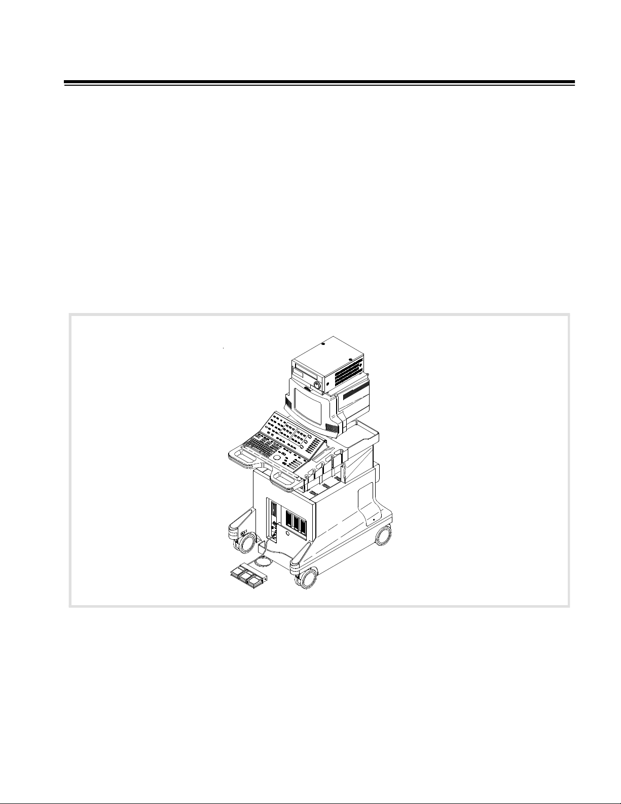
1-1 Introduction
The HDI 5000 Ultrasound System is a general-purpose, mobile, software-controlled, diagnostic ultrasound system. Its function is to acquire, process, and
display ultrasound data (Figure 1-1).
The operator can measure anatomical structures and generate reports for
health care professionals. The primary users are physicians and sonographers
in clinics and hospital departments that provide diagnostic ultrasound services.
The system has a basic set of imaging modes and measurement tools. There
also are modes and measurement tools which are only available when a specific mode or analysis package is purchased and enabled for customer use.
Upgrade security is controlled through the use of system-specific passwords
and software.
Figure 1-1 HDI 5000 Ultrasound System
HDI 5000 Service Manual 4730-0027-05 1-1
Page 23

1-1.1 Scanheads
The following scanhead types are supported:
• phased arrays
• linear arrays
• convex arrays
• compact linear array
• CW pencil probes
• multiplane transesophageal
Refer to: Section 4, "Theory of Operation", for front end theory; Section 6,
"Performance Tests", for operating parameters; and Section 13, "Configuration", for compatibility and replacement data.
1-1.2 Physical Description
Frame
The frame provides the primary structural support for the system. It has a
one-piece weldment. Front casters are swivel mounted with brake locks, rear
casters are fixed. Casters have integral shock mounts. The frame provides the
mounting base and swivel mechanism for the monitor module.
Card Cage
The removable card cage slides into the frame and is secured with screws. It
incorporates a center motherboard, or centerplane, with modules inserted
from the front and rear. The card cage is designed to allow for future motherboard, power supply, and fan module upgrades. Rear mounted fans provide
forced air cooling.
Eight slots are dedicated with appropriate shielding for channel boards. Two
additional shielded slots are available for the AIM+ PCB and a spare PCB.
External connections are provided through connectors mounted on brackets
attached directly to the card cage modules to eliminate cabling to remote connectors. All power supplies, disk drives and PCBs are slide-in modules with
card-edge connectors, switches, and LEDs, as necessary.
Peripheral Bay
Peripherals are installed into the cart with their control panels accessible to the
operator. Some peripheral controls also are available on the system control
panel for various OEM functions.
The open peripheral bay will accept a variety of peripherals. Peripherals are
mounted by one or more straps on a universal adapter plate. The plate can
easily be modified or replaced to accommodate future peripherals. A VCR
mounts on top of the monitor or in the OEM bay.
1-2 HDI 5000 Service Manual 4730-0027-05
Page 24

Control Panels
Operator controls consist of a full-size keyboard, a trackball and an array of
pushbuttons, toggle switches, slidepots, and rotary controls. Pressing certain
switches displays menus on the video screen. The trackball is then used to
select from the menus. Slidepots control TGC. Rotary controls are used for
gain control.
Included on the control module assembly are scanhead holders, storage trays
at the rear, and the handle used to move the system. The keyboard wrist rest
also serves as an ESD ground for the operator.
Monitor
The monitor assembly includes a single 15-inch, 120 or 220 Vac, 50/60 Hz
non-interlaced, all-digital monitor, monitor enclosure, and mounting for the
VCR. The VCR and monitor are removable for mobile systems. The monitor is
mounted on a swivel base that is mounted on the frame. Video resolution is
512 x 640 pixels in NTSC format and 512 x 768 pixels in PAL format.
The monitor senses the input video format and will also display interlaced
video with horizontal sync frequencies, nominally 15 kHz, with vertical sync
signal frequencies of 25 Hz and 30 Hz.
The monitor also accepts progressive video with horizontal sync frequencies,
nominally 31 kHz, with vertical sync signal frequencies between 50 Hz and
60 Hz.
Cables
Internal power cables are routed from the AC Input Module (ACIM) through the
right rear of the system (with the observer facing the rear of the system) to the
OEM or module requiring power. Internal signal cables are routed from the
Internal Interface Module (IIM) through the left rear of the system to each OEM
or the monitor. Refer to Section 11, "Cabling", for more information.
HDI 5000 Service Manual 4730-0027-05 1-3
Page 25

2 Specifications
2-1 Scanheads
contains the scanhead name that appears on the system monitor, the scanhead label, the scanhead frequency, and the Doppler frequency of system
scanheads.
Table 2-2 contains a summary of scanhead types, capabilities, and advan-
tages.
Table 2-1 Scanhead Information
Scanhead
Name
L7-4 38 mm 128 Linear Array L7-4 7.0 - 4.0 MHz 4.0 MHz
LI9-5 128 Linear Array LI9-5 9.0 - 5.0 MHz 5.0 MHz
LAP L9-5 128 Linear Array L9-5 9.0 - 5.0 MHz 6.0 MHz
L10-5 38 mm 192 Linear Array L10-5 10.0 - 5.0 MHz 6.0 MHz
L12-5 38 mm 192 Linear Array L12-5 12.0 - 5.0 MHz 6.0 MHz
L12-5 50 mm 256 Linear Array L12-5 12.0 - 5.0 MHz 6.0 MHz
CL10-5 128 Compact Linear Array CL10-5 10.0 - 5.0 MHz 6.0 MHz
C4-2 40 mm 128 Curved Array C4-2 4.0 - 2.0 MHz 2.5 MHz
C5-2 40 mm 128 Curved Array C5-2 5.0 - 2.0 MHz 2.5 MHz
C7-4 40 mm 128 Curved Array C7-4 7.0 - 4.0 MHz 4.0 MHz
CT8-4 40 mm 128 Curved Array CT8-4 8.0 - 4.0 MHz 6.0 MHz
C8-4v 11 mm 128 Curved Array C8-4v 8.0 - 4.0 MHz 5.0 MHz
C8-5 128 Curved Array C8-5 8.0 - 5.0 MHz 5.0 MHz
C9-5 ICT 8 mm 128 Curved Array C9-5 9.0 - 5.0 MHz 5.0 MHz
P3-2 20 mm 64 Phased Array P3-2 3.25 - 1.75 MHz 2.0 MHz
No.
Elem. Scanhead Label
Operating
Frequency
Doppler
Frequency
P4-2 20 mm 64 Phased Array P4-2 4.0 - 2.0 MHz 2.0 MHz
P5-3 16 mm 64 Phased Array P5-3 5.0 - 3.0 MHz 3.0 MHz
P6-3 28 mm 128 Phased Array P6-3 6.0 - 3.0 MHz 3.0 MHz
P7-4 16 mm 64 Phased Array P7-4 7.0 - 4.0 MHz 4.0 MHz
MPT7-4 10 mm 64 Phased Array MPT7-4 7.0 - 4.0 MHz 4.0 MHz
BPT9-5 2x64 Phased Array BPT9-5 9.0 - 5.0 MHz 6.0 MHz
TCD Static 1 D2 TC 2.0 MHz
D2 Static 2 D2 CW 2.0 MHz
D5 Static 2 D5 CW 5.0 MHz
D10 Static 2 D10 CW 10.0 MHz
HDI 5000 Service Manual 4730-0027-05 2-1
Page 26

Type Capabilities Advantages
Linear Array
Table 2-2 Scanhead Types, Capabilities, and Advantages
- L7-4 40 mm
- LI9-5 33 mm
- LAP L9-5
- L10-5 38 mm
- L12-5 38 mm
- L12-5 50 mm
- CL10-5
Curved Array
- C4-2 40R
- C5-2 40R
- C7-4 40 mm
-C8-4v
-CT8-4
-C8-5
- C9-5 8 mm
Phased Array
- P3-2 20 mm
- P4-2 20 mm
- P5-3 16 mm
- P6-3 28mm
- P7-4 16mm
- MPT7-4 10 mm
-BPT9-5
- 2D, M-mode,
pulsed Doppler,
Power, and Color
- 2D, M-mode,
pulsed Doppler,
Power, and Color
- 2D, M-mode,
pulsed Doppler,
CW Doppler (except P6-3), Power,
Color, and Color
M-mode
- Dynamic receive focus for optimal lateral resolution
- Multiple transmit focal zones
- Wide field of view
- High frame rate
- Excellent tissue definition and contrast resolution
- Excellent small parts imaging
- Combines the advantages of phased array and linear
array scanheads
- Multiple transmit focal zones
- Sector format with wide field of view at skin surface
- Aperture size consistent across sector results in
good lateral resolution
- Dynamic receive focus
- Excellent resolution and detail
- Design is lightweight and easy to use
- C5-2 has Contrast Specific Imaging capability
- Multiple transmit focal zones
- Dynamic receive focus
- MPT7-4 for transesophageal applications
- P3-2, P4-2, and P5-3 have Contrast Specific Imaging
capability
Pencil Probes
-D2 CW
- CW Doppler - Good continuous-wave Doppler sensitivity
-D5 CW
-D10 CW
- D2 TC - Pulsed Doppler - Good pulsed Doppler sensitivity
2-2 HDI 5000 Service Manual 4730-0027-05
Page 27

2-2 System Specifications
2-2.1 Physical Dimensions
• Width: 72 cm (28.35 in)
• Height: 157.5 cm (62 in) with VCR
142 cm (56 in) without VCR
122 cm (48 in) when monitor is removed for transport
• Depth: 110.4 cm (43.45 in)
• Weight: 172-200 kg (380-440 lbs) (depends upon the hardcopy device that
is installed)
2-2.2 System Architecture
• Digital broadband beamformer
• Extended signal processing
• Modular microcomputer structure
2-2.3 Imaging Modes
• Gray-scale 2D
• M-mode
• Doppler (PW and CW)
• Power (CPA and PMI)
• Color 2D
• Color M-Mode
• 3D Gray scale
• 3D Color Power Angio (3D CPA)
• Tissue Doppler Imaging (TDI)
• Tissue Harmonic Imaging (THI)
• SonoCT Real-time Compound Imaging
2-2.4 Update Methods
• Update or Duplex
• Triple Mode
• Simultaneous
2-2.5 Clinical Options
• Abdominal
• Abdominal Surgery
• Adult Cardiology
• Advanced Breast Imaging
• Cardiology Contrast Specific Imaging (CSI)
• Cerebrovascular
HDI 5000 Service Manual 4730-0027-05 2-3
Page 28

• General Imaging CSI
• Generic
• Gynecological and Fertility
• Musculoskeletal
• Neurosurgery
• Obstetrical
• Pediatric/Fetal Cardiology
• Pediatric General Imaging
• Peripheral Vascular
• Prostate
• Small Parts
• Transesophageal Cardiology
• Transcranial Doppler
• Vascular Surgery
2-2.6 Gain
• Slidepot controls for TGC (b/w , color, and TDI)
• 2D gain rotary control
• Doppler gain rotary control
• Color gain rotary control
2-2.7 Gray Shades
• 256 in 2D
• 256 in M-mode
• 256 in Doppler
2-2.8 Image Processing
• 2D graymaps
• 3D CPA and grayscale displays
• Chroma maps
• Doppler graymaps
• Dynamic range
• Color maps
• CPA maps
• CPA blending
• CPA display type
• Dynamic Motion Differentiation
2-4 HDI 5000 Service Manual 4730-0027-05
Page 29

2-2.9 Scan Conversion
• Sector for phased and curved array scanheads
• Rectangular for linear array scanheads, steered for Color and Doppler
imaging
• Up to 512 scan lines (scanhead and application dependent)
2-2.10 Frame Rate
• Scanhead dependent
• Frame rate control
2-2.11 User Control System
• Monitor brightness, contrast, lightbar, and background color controls
(default settings)
• Rotary controls
• Slidepot controls
• Keyboard
• Volume control
• Dedicated primary imaging controls
• Menus and superkeys for secondary imaging controls
• Color and tint controls for VCR playback
• Softkeys
• Digital Video Streaming (DVS) hand controller
• Footswitch
2-2.12 Digital Signal Processing
• Selectable compression (dynamic range)
• Automatic system bandwidth adjustment
• Selectable receive bandwidth patient optimization
• Software-controlled bandwidth, filter, and frequency optimization
• SonoCT Real-time Compound Imaging
• Intelligent Frame Rate Accelerator (multi-line processing)
2-2.13 Image Modification
• Zoom and pan of real-time or frozen 2D image
• Up to eight times magnification of 2D images
• High Definition Zoom
• Up to five times M-mode zoom
• 2D persistence
• Color persistence
• Color capture
• Color tag
HDI 5000 Service Manual 4730-0027-05 2-5
Page 30

• Color smoothing
• TDI Blend
2-2.14 Programmability
• Application and scanhead optimization
• Optimization for 3D, harmonic imaging, frame rate, and 2D/Color imaging
• Quick Save of user settings by application and scanhead
• On-screen programming for internal and external hardcopy devices
• User-defined acquisition protocols with the DVS option
• Analysis configuration
• Annotation text
2-2.15 Display Annotation
• Patient name and identification
• Institution
• Time and date
• Biopsy guide line
• Title, text, arrows, scanhead position, and body marker annotation
• Tissue specific body markers
• Additional Image Information
• Image Management status
• TI and MI values
• M cursor
• Doppler sample volume and angle correction
• Graphics control with the DVS option
2-2.16 Image Presentation
• Up/down orientation
• Left/right orientation
2-2.17 2D
• Image orientation marker
• Application-specific selectable graymaps
• 2D gain control
• Up to 5 transmit focal zones
• 2D persistence
• Dynamic range (compression curves)
• Chroma maps (gray-scale colorization)
• 2D sector size and steering
• Zoom
• HD Zoom
2-6 HDI 5000 Service Manual 4730-0027-05
Page 31

• 2D PRF control
• SonoCT Real-time Compound Imaging (Survey and Target modes)
2-2.18 3D
• Calibrated with position sensor and workstation
• Uncalibrated
• Cardiology with the MPT7-4 scanhead
2-2.19 M-Mode
• Four sweep speeds
• Time markers
• M-mode review
• M-mode zoom
• Three display sizes
2-2.20 Doppler
• Digital wall filters
• Pulsed wave (PRF range: 1.25–22.7 kHz)
• Continuous wave (Sample rate: 1.50–41.7 kHz)
• High PRF
• Adjustable sample volume (1.5–20 mm)
• Adjustable zero baseline
• Normal or inverted display
• Three display sizes
• Four sweep speeds
• Doppler gain control
• Doppler review
• Doppler graymaps
• Low flow capability
• Equivalent 5 MHz annotation
• High Q Automatic Doppler Results Display
• Angle correction
• Tissue Doppler Imaging for PW Doppler
2-2.21 Color and Tissue Doppler Imaging
• 2D Color/Tissue Doppler Imaging
• M-Mode Color
• Color gain control
• Selectable color maps
• Velocity, variance, and power displays
• Dynamic Motion Differentiation (DMD)
HDI 5000 Service Manual 4730-0027-05 2-7
Page 32

• Sensitivity
• Priority threshold
• Line density
• Color persistence
• Color smoothing
• Color tag
• Color capture
• Blending
• Frequency or velocity units
• Tissue Doppler Imaging for Color 2D and M-mode
2-2.22 Power and Power Motion Imaging
• 2D Color Power Angio Imaging/Power Motion Imaging
• 3D Color Power Angio Imaging
• Power Motion Imaging
• Selectable maps
• Dynamic Motion Differentiation
• Adjustable background (on or off)
• Display (Topography)
• Background (Blend)
• Dynamic Range
• Persistence
• Sensitivity
• Line Density
2-2.23 Physio
• ECG
• High-Level ECG
• Pulse
• Phono
• Auxiliary
Table 2-3 Physio ECG Performance Characteristics
Lower Frequency Cut-off 0.65 Hz ± 0.06 Hz
Upper Frequency Cut-off > 30 Hz ± 3.0 Hz
Nominal Input Amplitude 1 mVp-p
Minimum Sensitivity
5 X 10
-3
V
2-8 HDI 5000 Service Manual 4730-0027-05
Page 33

Table 2-4 Physio High Level ECG Performance Characteristics
Lower Frequency Cut-off 0.0 Hz ± 0.1 Hz
Upper Frequency Cut-off > 32 Hz ± 3.2 Hz
Gain Range 21 dB ± 1 dB
Minimum Sensitivity
2 X 10
-2
V
Table 2-5 Physio Pulse Performance Characteristics
Transducer Type Fukuda Denshi Other
Lower Frequency Cut-off 0.5 Hz ± 0.1 Hz 0.5 Hz ± 0.1 Hz
Upper Frequency Cut-off > 50 Hz > 50 Hz
Gain Range 45 dB ± 1 dB 35.5 dB ± 1 dB
Minimum Sensitivity
50 X 10
-6
V2 X 10
-3
V
Table 2-6 Physio Auxiliary Performance Characteristics
Lower Frequency Cut-off 0.5 Hz ± 0.1 Hz
Upper Frequency Cut-off > 800 Hz
Gain Range 28.5 dB ± 1 dB
Minimum Sensitivity
5 X 10⁻³V
Table 2-7 Physio Phono Performance Characteristics
Gain Range Minimum Sensitivity
Low
Phono
Filter
Off 28 ± 2.8 Hz 810 ±± 81 Hz 51 ± 1 dB 56 ± 1dB
Low 78 ± 7.8 Hz 385 ± 38.5 Hz 51 ± 1 dB 56 ± 1dB
Medium 90 ± 9.0 Hz 620 ± 62 Hz 51 ± 1 dB 56 ± 1dB
High 180 ± 18 Hz 800 ± 80 Hz 51 ± 1 dB 56 ± 1dB
Frequency
Cut-off
Upper
Frequency
Cut-off
Fukuda
Denshi Other
2-2.24 Triggering Modes
• Single (A or B channel)
• Dual (simultaneous A and B channels)
• Timer (A channel only, capture initiated by system clock)
2-2.25 Calculations (Power Calcs)
• General Imaging
• Cardiology
Fukuda
Denshi Other
50 X 10
15 X 10
15 X 10
10 X 10
-6
V 50 X 10-6V
-6
V 15 X 10-6V
-6
V 15 X 10-6V
-6
V 10 X 10-6V
• Analysis Configuration (Configurable CALCS)
2-2.26 Measurement Tools
• Distance
• Area
HDI 5000 Service Manual 4730-0027-05 2-9
Page 34

• Time/slope
• Volume
• Volume Flow
• Cardiac Output
• Heart rate
• High Q set region
• High Q mean trace
• High Q peak trace
• Calibration
• Optional hip angle
• Optional d:D ratio
• Optional % diameter reduction
• Optional % area reduction
2-2.27 Image Storage and Retrieval
• Cineloop Image Review, 2D
• Cineloop Image Review, 3D
• Doppler Review
• M-mode Review
• Image Management Option, DEFF-compatible, and for systems with the
DVS option, DICOM-compatible
• VCR Playback and Frame Grab
• Digital Video Streaming (DVS) Option
2-2.28 Optional Hardcopy Devices
• Super VHS VCR
• Multi-Image camera
• Color page printer
• Report printer
• Black-and-white page printer
2-2.29 External Connections
• RGB-S (Red, Green, Blue, and Sync) video 50/60 Hz frame rate, non-inter-
laced for external video monitors: Sub-D 9-pin connector
• RGB-S-CB (Red, Green, Blue, Sync, and Composite Blanking) video 25/30
Hz frame rate, interlaced for external hardcopy devices: Sub-D 15-pin connector (input and output connector)
• Composite gray scale for external hardcopy output: BNC connector
• VCR-S Video input/output: 9-pin DSUB connector
• VCR composite video output: BNC connector
• VCR composite input: BNC connector
2-10 HDI 5000 Service Manual 4730-0027-05
Page 35

• VCR audio output (left/right): dual RCA jacks
• VCR audio input (left/right): dual RCA jacks
• External line printer output, RS-232A: D-sub 9-pin connector
• System diagnostic and network I/O (Ethernet), USD port RS-232A: D-sub
9-pin connector (disconnect cable for systems with DVS option)
2-2.30 Electrical and Video Parameters
• 100Vac, (V∼), at 50 Hz or 60 Hz, 1450 VA
• 120Vac, (V∼), at 60 Hz, 1450 VA
• 220-240 Vac, (V∼), at 50 Hz, 1450 VA
• 220-240 Vac, (V∼), at 60 Hz, 1450 VA
• Integral AC line conditioner
• Power consumption: 800 watts; with optional OEMs, 1150 watts
2-2.31 Monitor
• One 15-inch, high-resolution, color monitor
• Provides a tilt and swivel adjustment
• Adjustable contrast, brightness, and lightbar controls
• Audio speakers
• Safety latches
• Microphone connector
2-2.32 Languages - System Software
• English
• French
• German
• Italian
2-2.33 Languages - User Interface Assemblies (Control
Panels)
• English, upper and lower
• French, upper and lower
• German, upper and lower
• Italian, upper and lower
• Danish, lower (use English upper)
• Norwegian, lower (use English upper)
• Swedish/Finnish, lower (use English upper)
2-2.34 Storage
• Unified cable management system
• Gel bottle
HDI 5000 Service Manual 4730-0027-05 2-11
Page 36

• Footswitch
• Two general purpose trays
2-2.35 Temperature, Pressure, and Humidity Limits
• Storage and Shipping
- High: 65°C (150°F), Low: -35°C (-31 °F)
- All at 1060 hPa to 303 hPa (1.05 ATM to 0. 3 ATM)
- 15% to 95% relative humidity
• Operating Environment
- High: 40°C Low: 10°C:
- All at 1060 hPa to 700 hPa (1.05 ATM to 0. 7 ATM)
- 15% to 95% relative humidity
2-2.36 Safety Requirements
• Classification:
- Class I with Type B, BF, and CF applied parts
- Ordinary Equipment
- Non-AP/APG
• Electromechanical safety standards met:
- CSA C22.2 No. 601.1, Canadian Standards Association, Medical Elec-
trical Equipment
- EN 60601-1, Second Edition, including Amendments 1 and 2, Euro-
pean Norm, Medical Electrical Equipment
- EN 60601-1-2, First Edition, European Norm, Collateral Standard Elec-
tromagnetic Compatibility
- IEC 1157:1992, International Electrotechnical Commission, Require-
ments for the declaration of acoustic output of medical diagnostic ultrasonic equipment
- JIS T-1000 Series, Japanese Industrial Standard, Medical Electrical
Equipment
- UL 2601-1, Underwriters Laboratories, Medical Electrical Equipment
2-12 HDI 5000 Service Manual 4730-0027-05
Page 37

• Agency approvals:
- Canadian Standards Association (CSA)
- Japanese Ministry of Health and Welfare (pending)
- ISO 9001, EN46001 Quality Assurance Standard; Certificate
#FM28256 issued by the British Standards Institution (BSI) for Quality
Systems
- CE Marked to the European Community Medical Device Directive 93/
42/EEC per Annex II, as a Class IIa device, in accordance with Annex
IX (BSI Certificate #0604)
ATL Ultrasound reserves the right to change specifications contained herein or
discontinue manufacture at any time without prior notice. Current specifications are supplied with each system.
HDI 5000 Service Manual 4730-0027-05 2-13
Page 38

3 Safety
3-1 Safety Information
3-1.1 Introduction
Please read this information before using an ATL ultrasound system. It
applies to the ultrasound system, scanheads, recording devices, and any
optional equipment.
This device is intended for use by, or by the order of, and under the supervision of a licensed physician qualified to direct the use of the device.
In this manual, a WARNING describes precautions necessary to prevent injury
or loss of life.
In this manual, a CAUTION describes precautions necessary to protect the
equipment.
3-1.2 Electrical Safety
This equipment has been Certified by a recognized third-party testing agency
as a Class I device with Type B non-isolated and Type BF and Type CF isolated patient-applied parts. For maximum safety observe these warnings:
WARNINGS • Before connecting and applying power, all ACIM (power input panel)
mounting screws must be in place and properly secured to complete the
system ground path.
• Shock hazards may exist if this system is not properly grounded. Protec-
tion against electrical shock is provided by grounding the chassis with a
3-wire cable and plug. The system must be plugged into a hospital-grade
three-hole outlet. The grounding wire must not be removed or defeated.
• Do not remove the protective covers on the system; hazardous voltages
are present inside. Cabinet panels must be in place while the system is in
use. All internal adjustments and replacements must be made by a qualified ATL customer support representative.
• Do not operate this system in the presence of flammable gases or anes-
thetics. Explosion can result.
• Always inspect the scanhead or pencil probe face, housing, and cable
before use. Do not use the scanhead or pencil probe if the face is cracked,
chipped, or torn, the housing is damaged, or the cable is abraded.
• Always disconnect the system from the wall outlet before cleaning the
system.
HDI 5000 Service Manual 4730-0027-05 3-1
Page 39

WARNINGS • Connection of optional devices not supplied by ATL could result in electrical
shock. When such optional devices are connected to your ultrasound system, ensure that the total system chassis risk current does not exceed 100
µA for 120 Vac systems and 500 µA for 230 Vac systems.
• In general, only the area of the scanhead acoustic window is watertight.
Except where specified in specific scanhead cleaning instructions, do not
immerse the remainder of a scanhead in any liquid.
CAUTIONS • Always place the system ON/STANDBY switch to STANDBY for five to ten
seconds before setting the system I/O circuit breaker to OFF.
• Always wait five to ten seconds after placing the ON/STANDBY switch to
STANDBY before placing the switch to ON. A power-down sequence, similar to the initialization that occurs when power is first turned on, saves certain operating parameters and turns off power supplies in a sequential
order. Review the power subsystem discussion in Section 4, "Theory of
Operation".
• Always verify that the power cord voltage label matches the voltage on the
device before plugging in the power cord. On 230 Volt systems VCR power
is 230 Volts but the monitor is 120 Volts. Applying 230 Volts to the monitor
will destroy it.
• This equipment contains components that are electrostatic sensitive.
Proper static procedures, protection and equipment must be used prior to
opening and during handling of this equipment. Failure to use ESD procedures will cause damage to these components. Such damage to components is not covered by ATL warranties.
3-1.3 Mechanical Safety
WARNINGS • Be aware of the casters, especially when moving the system. The system
can weigh 200 kg (440 pounds), depending upon configuration, and it
could cause injury to you or others if it rolls over feet or into shins.
• ATL recommends pushing the system, instead of pulling it, and exercising
special caution when going up or down ramps.
• Position external hardcopy devices away from the system. Ensure that
they are secure. Do not stack them on the system.
CAUTIONS • Ensure that scanhead cables are secure. Use the cable management sys-
tem to ensure that scanhead cables are protected from damage.
• Electrostatic discharge (ESD) can amount to a significant voltage which
may cause damage to PCBs or other system components. The following
precautions can reduce ESD: anti-static spray on carpets; anti-static spray
on linoleum; anti-static mats; use of a ground wire connection between the
system and the patient table or bed; use of the ESD pads on the system
handles and the wrist support of the system keyboard.
3-2 HDI 5000 Service Manual 4730-0027-05
Page 40

3-1.4 Equipment Protection
CAUTIONS • Excessive bending or twisting of a scanhead or pencil probe cable may
cause failure or intermittent operation of the system.
• Do not sterilize a scanhead using gas or heat methods. Never autoclave a
scanhead or expose it to temperatures exceeding 55°C (131°F). These
sterilization methods may permanently damage the scanhead. For disinfection and sterilization instructions, see the Using Disinfectants and Gels
manual, part number 4700-0249-XX.
• Inspect the system power cord and plug on a regular basis. Ensure that
they are not damaged in any way.
• The power supplies continue to operate when the system is in standby.
Ensure that the circuit breaker is off, before unplugging the system from
the wall outlet.
• For optimal performance, your ATL ultrasound system should be con-
nected to a 15 Ampere dedicated circuit with an isolated ground for 100V/
120V systems or a 7.5 Ampere dedicated circuit with an isolated ground
for 220V/240V systems.
HDI 5000 Service Manual 4730-0027-05 3-3
Page 41

3-2 Safety Symbol Definitions
The International Electrotechnical Commission (IEC) has established a set of
symbols to classify electrical connections and warn of potential hazards on
medical electronic equipment.
These symbols are used on the outside of the system:
Grounded patient connection. Protection against electrical
shock is provided by connection of chassis to the safety ground.
Isolated patient connection.
Isolated patient connection for applied parts in direct contact
with major vessels. (Type CF)
/
I and O on the circuit breaker represent ON and OFF.
On the power switch, represents ON and STANDBY.
/
This symbol identifies a safety note. Ensure you understand the
function of this control before using it. Refer to the appropriate
section in the Reference Manual for an explanation of the control.
Drip-proof appliance on scanhead, pencil probe, or footswitch.
This instrument may be safely handled in a damp environment.
IPX-1
Water-proof appliance (scanheads only). This instrument may
be safely immersed.
IPX-7
Identifies equipotential ground (located next to ground stud on
the rear panel).
The following symbols are used inside the system:
Identifies high voltage components operating above 750 Vac
(RMS) or 750 Vdc.
Identifies the point where the system safety ground is fastened
to the chassis.
Save these instructions.
3-4 HDI 5000 Service Manual 4730-0027-05
Page 42

4 Theory of Operation
4-1 Introduction
This section describes the electronics of the system and how the echo data
flows through it. Also included are descriptions of the control architecture, software architecture, and the packaging.
4-2 Operating System
The software operating system is supported by X-Windows software. X-Windows is an industry-standard software system that allows the development of
graphical user interfaces, which consist of windows, graphics, and displayed
text.
X-Windows is made up of a server and a client. The server resides on the
Pixel Conversion Module (PCM), and the client resides on the Central Processing Unit (CPU).
• The server completely controls all input and output devices
• The client communicates with the server using Ethernet, an asynchronous
byte-stream protocol
• CPU software controls all ultrasound functions
4-3 Subsystems
The electronics of the system can be divided into five basic functional subsystems (Figure 4-1). Each subsystem contains several modules that perform
specific functions within the subsystem:
• Power Subsystem
• Control Subsystem
• Acquisition Subsystem
• Processing Subsystem
• Display Subsystem
HDI 5000 Service Manual 4730-0027-05 4-1
Page 43

4-3.1 System Block Diagram
Control
Acquisition
RF Bus
Processing
Figure 4-1 System Block Diagram
4-3.2 Power Subsystem
The Power Subsystem (Figure 4-2) includes AC Input Module (ACIM) and
Power Supply Module (PSM). The power subsystem is monitored by the Front
End Controller (FEC) using the Front End Processor (FEP) bus.
SCIP Bus
Image Bus
Power
Display
Network and
Analysis
All modules
Monitor,
VCR,
peripherals
Network
System power is not field-configurable. Four versions of the ACIM provide
100-120 Vac/60 Hz, 100-120 Vac/50 Hz, 240 Vac/50 Hz, and 230 Vac/60 Hz
configurations.
The Power Subsystem also includes a shielded line cord, On/Off circuit
breaker, a ferro-resonant isolation transformer, a linear transformer, resonant
filter capacitors, manual ON/STANDBY switch (on user interface), software-controlled power ON/STANDBY switch (controlled by CPU), and overload protection in the individual power supplies (watchdog circuitry on FEC).
All power supplies plug directly into the centerplane to supply all DC power.
There are no power supply adjustments. The subsystem converts high voltage
AC into DC voltages, and buses these DC voltages over the centerplane to the
modules that require them. Status LEDs on the ACIM and PSM are covered in
Section 9, "Troubleshooting". Refer to paragraph 4-4.11 for Output Power
Monitor theory.
4-2 HDI 5000 Service Manual 4730-0027-05
Page 44

The voltages supplied by the PSM are:
• +5 Vdc
• -5.2 Vdc
• ±6 Vdc
• ±15 Vdc
• ±12 Vdc
• +12 to +24 Vdc (fans)
• ±115 Vdc (0 to +HV and 0 to -HV, for variable pulsers)
Power distribution group
FEP bus
ACIM (PS4) On/Standby
Circuit
AC
power
input
breaker
Monitor, 115 V ± 10%
Environ. bus
+155VDC
PIM
AIM+
and
AIFOM
temp
sensors
Power
supply
module
PSM
(PS1)
(PS2)
(PS3)
Temp
Sensor
OEM
OEM
1200 VA
xfmr
155 Vac
OEM
xfmr
Fuse
250 V/12 A
OEM relay
(controlled by
on/standby
switch)
Diode
bridge
Figure 4-2 Power Subsystem
Power Subsystem Operation
The Power Subsystem operates in three modes:
• Power-Up
-5.2 Vdc
±12 Vdc
+12 to +24 Vdc fans (via ACIM)
FEC power failure
FEC HV DC OK (pulser enable)
Sys init*
HV EN
3.3V (not currently used)
+5 Vdc
±6 Vdc
±15 Vdc
±15 - 115 Vdc pulser/mux
(0 - +HV) (0 - -HV)
Brief initialization period after system circuit breaker is turned on
• STANDBY
ON/STANDBY switch remains in STANDBY. Power supplies on: no power
to card cage, or internal OEMs; system INIT* set low.
CAUTION HVDC is present on the Centerplane.
• ON
ON/STANDBY switch set to ON. All power rails turned on, system initialized, no faults detected, OEM voltages enabled
HDI 5000 Service Manual 4730-0027-05 4-3
Page 45

Refer to paragraph 4-4.11, Output Power Monitor Theory for information about
watchdog circuits mentioned below.
Power-Up Mode - occurs when the system circuit breaker is turned on. During
power-on:
• PSM powers its ON/STANDBY circuit
• All Power Subsystem outputs are disabled
• PSM resets latches to enable the Vicor power supplies
• The system is placed into STANDBY mode
STANDBY to On Mode - PSM monitors the ON/STANDBY signal from UIF via
the SCIP bus. When the ON/STANDBY switch is set to ON, the following
occurs:
• Card cage voltages are enabled and monitored by the FEC for operation
within ON mode limits.
• Fans start at full speed. After timeout, speed is adjusted to minimize fan
noise while maintaining normal operating temperature.
• +5 V Vicor power supply comes up.
• System begins initialization; system INIT* set to high.
• OEM power is enabled.
• PSM watchdog circuit sends data to FEC regarding HV voltages.
• PSM monitors Power Subsystem and airstream temperature.
• FEC interprets the voltage, current, and temperature values and responds
by updating ACIM LEDs.
• DVS Module powers up.
On to STANDBY Mode - PSM monitors the ON/STANDBY signal from CPU
via the SCIP bus. When the ON/STANDBY switch is set to STANDBY, the system is set to STANDBY mode as follows:
• Contents of static RAM are copied to non-volatile RAM (time, temperature,
status).
• DVS Module powers down. System CPU starts time-out for system shutdown.
• FEC requests permission to enter STANDBY mode from CPU via SCIP bus
and starts a time-out to prevent software lockup.
• PSM watchdog circuit stops sending data to FEC. If FEC does not respond
to PSM watchdog circuit, PSM shuts down HV supply.
• CPU initiates a wait period and saves active operating parameters to
non-volatile RAM. If CPU does not respond, FEC proceeds with standby
sequence.
• HV supply disabled.
• Power removed from internal OEMs.
• System INIT* is set low to reset the system.
• Card cage voltages are disabled (fans are off).
4-4 HDI 5000 Service Manual 4730-0027-05
Page 46

AC Input Module (ACIM) - PS4
• AC input receptacle (Figure 4-3), I/O circuit breaker (main power switch),
ground stud and LED display
- LEDs provide diagnostic information (See Section 9, "Troubleshooting")
• Provides power interface to transformers and OEMs
• Provides HVDC to PSM
SQUCAP
SQUFERSINFER
I/O
Circuit
Breaker
100-120V 50Hz
100-120V 60Hz
240V 50Hz
230V 60Hz
Power Supply Module (PSM) - PS1, PS2, PS3
• Provides -5.2 Vdc, +5 Vdc, ±6 Vdc, +3.3 Vdc (not currently used), +12 Vdc
OEM Control
+12 Vdc to +24 Vdc
HVDC
+155 V
ACIM
PS4
Fans
VCR
Reg
Reg
Rectifier
Relay
Monitor
Printer
Figure 4-3 ACIM Module
to +24 Vdc, ±12 Vdc, ±15 Vdc, 0 to +HV, and 0 to -HV
PSM
PS1
PS2
PS3
• Monitors thermistors located on PCBs around the card cage (PSM, AIM+,
PIM, and AIFOM). Averages temperature from thermistors and controls
voltage to system fans. (Power supply is disabled in Standby. Fans are not
functional.)
• Variable "HV powers HV pulsers and scanheads with HV multiplexers.
Generates voltages from ±15 Vdc to ±115 Vdc
• Disables all power supplies if HVDC goes below +90 Vdc
• HV watchdog circuit detects if the FEC fails to monitor the HV voltages/cur-
rents. Enables the user to shut down the system if the FEC fails or is not
installed
HDI 5000 Service Manual 4730-0027-05 4-5
Page 47

• Monitors HVDC and notifies the CPU if it goes below 100 Vdc. CPU uses
this information to protect storage devices against data corruption
• Relays status of HVDC from the ACIM to the FEC
• PSM diagnostics are performed by the FEC, voltage, current, and system
temperature monitoring
• Monitors individual power supplies for over-voltage conditions and shuts
down faulty power supplies
• Contains system “standby” circuitry
• Enables OEM power
4-3.3 Control Subsystem
The Control Subsystem (Figure 4-4) monitors user input, gives status to the
user through UIF, provides system coordination, provides data storage, and
service access.
The Control Subsystem consists of:
• System CPU Module (CPU)
• Image Memory Module (IMEM)
• Disk Drive ECG Assembly (DDEA)
Image
Bus
User Interface (UIF)
IMEM
Control Subsystem
Figure 4-4 Control Subsystem Block Diagram
A8B
IIM
PCM
CPU
Hard Drive
Optical Drive
(DDEA)
A6B
SCSI
Bus
A1F
Ethernet
SCIP Bus
Network
Interface
and
Analysis
Acquisition
Subsystem
Processing
Subsystem
Display
Subsystem
4-6 HDI 5000 Service Manual 4730-0027-05
Page 48

System CPU (CPU) - A6B
• Motorola 68040 microprocessor; VX Works operating system.
• Loads modules requiring operating software at boot-up.
• Transfers scanhead tables to the FEC as needed.
• Generates coefficients and data tables for Processing Subsystem.
• Performs analysis calculations.
• Queries Power Subsystem for Acoustic Power & Intensity (AP&I) status.
• X-bus interface to Display Subsystem (PCM).
• Time and date.
• Stores user setups.
• 32 Mb RAM for Image Management. 48 Mb RAM for systems with Perfor-
mance 2000 upgrade (17X.XX software). Additional RAM supports addition
of the Performance 2000 feature set.
• Verifies major H/W, F/W, S/W revision, upgrade compatibility.
• Performs system diagnostics and stores results.
• Provides Ethernet connection to the DVS Module.
Image Memory (IMEM) - A8B
• 64 Mb RAM for data storage
• Provides Image Bus arbitration, control, and timing
• Reports PCB board revision and SIMM data to system CPU
• Stores data from ADAPTR for transfer to PSP or PCM, or both
• Stores data from PCM for transfer to PSP during framegrab
• History buffers for 2D Echo, 2D Color, M-mode Echo, Color M-mode,
Scrolling Doppler, Physio, and High Q Analysis
Disk Drive ECG Assembly (DDEA) - A1F
• Houses optical drive and hard drive of varying capacities. All hard drives
formatted to 2100 Mb due to operating system constraints.
• Provides SCSI interface to the optical and hard drives
• Provides +5 Vdc and +12 Vdc power to the optical and hard drives
• Connects and low pass filters footswitch signals to the PCM
• Amplifies and filters ECG, Aux ECG, Respiration, Channel A, and Channel
B signals. Routes signals to ADAPTR
• Reports PCB board revision to system CPU
HDI 5000 Service Manual 4730-0027-05 4-7
Page 49

4-3.4 Acquisition Subsystem
The Acquisition Subsystem (Figure 4-5) controls the transducer, generates the
electrical impulse (pulse) that creates the sound wave, and converts the
returning echo information into digital data.
The Acquisition Subsystem consists of:
• Front End Controller Module (FEC)
• Scanhead Select Module (S/HSEL)
• Eight Channel Boards (CB0 - CB7)
• Analog Interface Module Plus (AIM+)
• Regulator Module (only in systems with a depopulated AIM+ PCB shipped
prior to April 1998, PCB P/N 7500-1026-XX)
Acquisition group
CW/PW
(pencil)
Array
(scanhead)
Array
(scanhead)
Array
(scanhead)
Scanhead
Pulser
0 - 120
Regulator
Module
Select
HV
HV
TGC
Array echo
TGC buses
Front
End
Control
(FEC)
A4F
Analog
Interface
Module (AIM+)
Pulser out
A6F
Front end buses
A5F
SCIP Bus
Figure 4-5 Acquisition Subsystem
CB0 - CB7
A7F - A14F
Ch. Boards
Rx
Static probe echo
R
F
B
u
s
e
s
4-8 HDI 5000 Service Manual 4730-0027-05
Page 50

Front End Controller (FEC) - A4F ()
The FEC downloads operational parameters from CPU and provides real-time
control of the front end for transmit, receive, and beamforming functions.
• Interfaces with CPU via SCIP bus to determine scanning sequence and
mode of operation.
• Provides timing signals for Tx and Rx cycle.
• Controls scanhead selection, personality, and HV Mux through the AIM+
and S/HSEL.
• Sends scanhead operating parameters to Channel Boards through FEC
bus.
• Receives scanning sequence instructions from CPU and generates digital
TGC, PRI and other timing sequencing.
• Controls sample volume cursor position to the AIFOM.
• Monitors voltages from PSM via FEP bus.
• Generates RF headers for image data to AIFOM.
• AP&I power monitor control.
• Bus Interfaces: SCSI, FEP, Clock, SHC, TGC, RF, TTag, FEC, Sync, SC,
and SCAN (see paragraph 4-5).
• Changes to FEC for 17X.XX systems allow more imaging modes to be
selected, such as SonoCT Real-time Compound Imaging.
• Supports dual AIFOMs for 17X.XX systems.
• Integrated CSI and Pulse Inversion.
Channel Boards - A7F through A14F
• Channel Board RAM is loaded with operational parameters for selected
scanhead. Parameters define Tx, Rx and beamforming behavior for each
scan line and depth. Transfers data under FEC control for each new PRI
• Transmit apodization/power control under FEC control
• Transmits to, and receives from transducer elements under FEC control
• Digitizes RF, beamforms, adds TGC, and sends digital Rx data to Process-
ing Subsystem over the RF buses for all modes
• Anti-aliasing filtering
• Static CW RF receive and mix to baseband (Channel board 0)
• Static PW transmit, receive, and process (Channel board 1)
• Steered CW receive and mix to baseband
• 512 channel
• Bus Interfaces: Summing, TGC, RF, Clocks, Timing, FEC, and FEP
HDI 5000 Service Manual 4730-0027-05 4-9
Page 51

S/H
SEL
128
16
16
16
16 Rx
16 Tx
Mux
CB0
16
CB1
CB2
Digital
Beamformer
Transmit
Control
CB6
CB7
A7F - A14F
Summing Bus
Clocks,
Timing
Bus, TGC
FEC Bus
Regulated
HV
Interfaces
RF
Buses
Figure 4-6 Channel Boards - A7F through A14F
Analog Interface Module Plus (AIM+) - A5F
• Generates system clock frequency of 240 MHz
• Subdivides the clock frequency into 120, 80, 60, 48, 30, and 24 MHz
• Supplies clock frequencies (80, 60, 48, 30, and 24) to centerplane for distri-
bution to other PCBs
• Supplies 120 MHz to S/HSEL
A
I
F
O
M
• Receives +5 Vdc, +6 Vdc, ±15 Vdc, ±80 Vdc, and -5.2V from centerplane
and regulates ±15 Vdc to become +10 Vdc, and ±12 Vdc
• Supplies ±80 Vdc, ±12 Vdc, +10 Vdc, and +5 Vdc to S/HSEL
• Generates and monitors two analog TGC voltages. Supplies TGC signals
to S/HSEL for use by Channel PCBs
• Receives I/Q CW signals from Channel PCBs for steered and static CW
processing
• Thump filter, variable wall filters, and low pass anti aliasing filters for I/Q
• Digitizes I and Q using 16 bit AD converters. Exports I and Q to RF buses
• Sends S/HSEL status and personality data to FEC via FEP bus
• Buffers and provides HV Mux selection data to the scanhead
• FEP bus interface
• Relay control for desired scanhead on S/HSEL
• Thermal sensor to monitor internal system temperature for fan speed con-
trol
• Scanhead temperature sensing to FEC via FEP
• Supplies high voltage to HV Muxes on S/HSEL
• Supports acquisition with the MPT7-4 scanhead (motor control for 3D
acquisition) on Performance 2000 systems (17X.XX software)
4-10 HDI 5000 Service Manual 4730-0027-05
Page 52

Regulator Module - A6F
NOTE The functions listed below were moved to the AIM+ PCB for sys-
tems shipped after April 1998.
• Regulates HV from PSM to Channel PCBs
• Controlled by FEP Bus interface
Scanhead Select Module (S/HSEL)
• Selects between the scanhead connectors
• Interfaces between the front-end PCBs and the scanhead
• Connects the TGC control voltages from the AIM+ to the Channel boards
• Connects the baseband CW quadrature current bus from the Channel
boards to the AIM+
• Connects the 120 MHz clock signal from the AIM+ to the Regulator Module
• Connection and mux for transducer elements and the channel boards for
array transducer
• Provides connection for static CW and TCD transducers
4-3.5 Processing Subsystem
The Processing Subsystem (Figure 4-7) filters the echo information, and transforms it for display processing. The processing subsystem generates Doppler
audio and routes various audio sources to the speakers and VCR. The processing subsystem digitizes, filters, and transforms ECG data for the display.
Post-processing and data storage for zoom take place in this subsystem.
The Processing Subsystem consists of:
• Single Advanced IF Output Module (AIFOM) on systems below 17X.XX
software
• Dual Advanced IF Output Modules (Master and Slave AIFOMs) on 17X.XX
systems
• Signal Processing Module (SPM)
• Advanced Digital Audio and Physio Translator Module (ADAPTR)
HDI 5000 Service Manual 4730-0027-05 4-11
Page 53

1
Slave
Acquisition
Subsystem
RF
Buses
DDEA
IIM
Dual AIFOMs used only in 17X.XX systems and above.
1
AIFOM
Master
AIFOM
A13B
ECG
Microphone
AQ
Bus
A12B
SPM
Figure 4-7 Processing Subsystem
Advanced Intermediate Frequency Output Module (AIFOM) A12B/A13B
• Processes 2D, Color Flow, Spectral Doppler, and M-mode data
• Synthetic aperture
• Dynamic Range
A11B
PD
Bus
ADAPTR
A9B
Image Bus
Audio
Image
Memory
IMM
(Speakers)
VCR
• Demodulates all beamformer data (except CW Doppler) into In-phase and
Quadrature data (I and Q)
• Additional processes for 2D and M-mode echo data are amplitude detection, multi-zone reconstruction, and multi-rate filtering
• CW Doppler passes through AIFOM without being processed
• Uses 24 MHz clock to time data onto the PCB from the RF buses and con-
trol data flow through the PCB
• Receives 60 MHz and 40 MHz clocks from the centerplane and divides the
signals for use in MOP and SCIP circuits
• Dual AIFOMs installed on systems with 17X.XX software. All other systems
have single AIFOM.
• A13 is Master AIFOM. A12 is Slave. Controlled by system software
• A12 AIFOM is used only for high frame rate mode and for Intelligent Frame
Rate Accelerator operation
4-12 HDI 5000 Service Manual 4730-0027-05
Page 54

Signal Processing Module (SPM) - A11B
• Processes Color Flow, Spectral Doppler, and M-mode data. Also pro-
cesses 2D on systems with 124.13 software and up
• Processes 2D persistence and Dynamic Contrast Enhancement on sys-
tems with 124.13 software and up
• Velocity, variance, and power
• Color Flow processes include Dynamic Motion Differentiation (DMD), wall
filter, 2D auto correlation, and spectral estimation
• Color Flow processing include persistence, hole filling, segmentation
• Spectral Doppler processing includes wall filter, gain, FFT, gap fill, averag-
ing, interpolation, and High Q Automatic Doppler calculations (mean and
peak)
• Doppler processing includes Hilbert Transformation to generate forward
and reverse audio
• M-mode processing includes temporal filtering/decimation
Signal Processing Module Plus (SPM+) - A11B (17X.XX
Systems and Above)
• All signal paths go through SPM+. All data path functions are programmed
through software
• Contains two daughterboards with DSPs for additional processing power
• Operating speed increased from 32 MHz to 40 MHz
• Performs SonoCT Real-time Compound Imaging functions
Advanced Digital Audio, Physio, and Translator Module
(ADAPTR) - A9B
• Translates Acquisition Bus (AQ) or Processed Data (PD) bus headers to
image bus addresses as part of the transfer to AQ bus and PD bus data to
Cineloop/history buffers in IMEM
• Maintains buffer descriptors in IMEM for all data types output by this mod-
ule
• Provides bus arbitration, error monitoring, and clock generation for the AQ
and PD bus
• Provides ECG A/D conversion, filtering, display gain/positioning
• Triggers front end acquisition based on ECG R-wave detection
• Sends heart rate info to CPU based on ECG R-wave detection
• Provides a D/A audio reproduction path for Doppler audio
• Selects speaker source between Doppler and VCR
• Provides volume control and mute for speakers
• Routes microphone to VCR
• Provides audio connectors for external VCR
• Processes microphone and VCR audio; A/D conversion, gain and filtering
HDI 5000 Service Manual 4730-0027-05 4-13
Page 55

4-3.6 Display Subsystem
The Display Subsystem (Figure 4-8) formats the echo information for display,
and transfers it to the video monitor and peripheral devices.
The Display Subsystem consists of:
• User Interface Module (UIM)
• Pixel Space Processors 1 and 2 (PSP1 and PSP2)
• Pixel Conversion Module (PCM)
• Peripheral Interface Module (PIM)
• Internal Interface Module (IIM)
Ethernet
CPU
Processing
Subsystem,
Image
Memory
Image
Bus
UIF
UIF
PCM
A3B
PSP
A4B, A5B
UIM
PIM
Figure 4-8 Display Subsystem
User Interface Module (UIM)
A2B
UIF
Clocks;
Control
IIM
A1B
Internal
Monitor
Internal
Hardcopy
Internal
VCR
Microphone
Speakers
External
Hardcopy
External
Monitor
External
VCR
DVS
• Upper and lower control panels (UCP and LCP)
• User Interface Module (UIM)
• Controlled by PIM
• User interface for pull down menus for functions which are user options
and dedicated controls for functions used during examinations
NOTE System self-diagnostics includes the UIM as part of the Display Sub-
system.
4-14 HDI 5000 Service Manual 4730-0027-05
Page 56

Pixel Space Processor (PSP1 & 2) - A5B, A4B
• Acquires image data from IMEM
• 2D scan conversion
• Zoom
• Static and scrolling graphics
• Freeze (buffer memory located on PSP1)
Pixel Conversion Module (PCM) - A3B
• Controls UIF window displays (X-windows)
• Gray scale and color LUTs (look-up tables)
• Converts non-interlaced 60/50Hz to interlaced 30/25Hz for OEMs
• Gray and color bar generator
• Hidden digital data
• Provides image background and image windows
• Monitors user interaction including keystrokes, trackball movement, and
footswitch activity
• All graphics and overlay capabilities
• User interface windows, menus, and icons
• Framegrab functions
• Routes DVS overlay graphics from/to the PIM
Peripheral Interface Module (PIM) - A2B
• Controls UIF through UIM (control PIM)
• Encode/Decode NTSC and PAL composite Y/C video (video PIM)
• System video sync (video clock) originates on AIM+ (video PIM)
• Controls internal OEMs through IIM (video PIM)
• Sends digital video to and from the DVS Module (video PIM)
• Routes DVS overlay graphics to the PCM through the PIM and to the mon-
itor (video PIM)
Internal Interface Module (IIM) - A1B
• Routes video signals to/from monitor, hardcopy devices, and VCR. (No
video processing is done on IIM)
• Buffers and routes audio signals to/from VCR
• Amplifies and routes audio signals to the speakers in the monitor housing
• Routes logic signals to/from the monitor, hardcopy devices, and UIM
• Buffers the signal from the microphone to the system
HDI 5000 Service Manual 4730-0027-05 4-15
Page 57

4-4 Data Paths
Data path block diagrams are contained in Figure 4-9 through Figure 4-24.
The data paths in the illustrations are shown by thick dashed lines. Solid thin
lines indicate that a connection exists but is not used for that data path.
4-4.1 2D/PW/Color Front End Signal Path
1
Timing and control bus connect to each Channel Board. (Not shown)
Array
scanheads
CW
S/H SEL
Relay matrix
2
Regulated HV rails connect to each Channel Board. (Not shown)
3
Regulator Module functions incorporated into AIM+ PCB, April 1998.
CB6
CB5
CB4
CB3
CB2
CB1
CB0
Channel
Board
CB7
FEC
1
Timing and control buses
Figure 4-9 2D/PW/Color Front End Signal Path
4-4.2 2D Data Path
DDEA
S/H
Sel
Array
S/H
REG
MOD
CH BD
FEC
AIM+
AIFOM
SPM
PSMACIM
AIM+ +
Regulator
3
Voltage outputs
ADAPTR
Module
IMAGE
MEM
2
Audio
PCM
PSP
2
Regulated
HV rails
PIM
RF
Buses
IIM
Figure 4-10 2D Signal Path (108.XX Systems and Below)
4-16 HDI 5000 Service Manual 4730-0027-05
Page 58

DDEA
IMAGE
MEM
Array
S/H
Array
S/H
S/H
Sel
REG
MOD
FEC
AIM+
CH BD
AIFOM
SPM
ADAPTR
2
PCM
PIM
PSP
Audio
Figure 4-11 2D Signal Path (124.13 through 127.XX Systems)
IMAGE
MEM
PCM
PIM
2
Audio
PSP
S/H
Sel
DDEA
REG
MOD
FEC
AIM+
CH BD
AIFOM
AIFOM
ADAPTR
SPM
IIM
IIM
Figure 4-12 2D Signal Path (17X.XX Systems and Above)
HDI 5000 Service Manual 4730-0027-05 4-17
Page 59

4-4.3 PW Doppler and Color Data Path
Array
S/H
Array
S/H
S/H
Sel
DDEA
REG
MOD
FEC
AIM+
CH BD
AIFOM
SPM
Ext.
Audio
ADAPTR
2
IMEM
PCM
PSP
Audio
Figure 4-13 PW Doppler and Color Path (108.XX Systems)
S/H
Sel
DDEA
REG
MOD
FEC
AIM+
CH BD
Ext.
Audio
AIFOM
ADAPTR
SPM
IMEM
PCM
2
Audio
PSP
PIM
PIM
IIM
IIM
Figure 4-14 PW Doppler and Color Path (124.13 Through 127.XX Systems)
Array
S/H
S/H
Sel
DDEA
REG
MOD
FEC
AIM+
CH BD
AIFOM
AIFOM
SPM
Ext.
Audio
ADAPTR
IMEM
PCM
PIM
2
Audio
PSP
Figure 4-15 PW Doppler and Color Path (17X.XX Systems)
IIM
4-18 HDI 5000 Service Manual 4730-0027-05
Page 60

4-4.4 Static PW Front End Signal Path
1 Timing and control bus connect to each Channel Board. (Not shown)
Regulated HV rails connect to each Channel Board. (Not shown)
S/H SEL
Array
scanheads
Relay matrix
CW
2
3
Regulator Module functions incorporated into AIM+ PCB, April 1998.
CB6
CB5
CB4
CB3
CB2
CB1
Signal path uses only CB1
CB0
Channel
Board
AIM+ +
CB7
RF
Buses
FEC
1
Timing and control buses
PSMACIM
3
Voltage
outputs
Regulator
Module
Figure 4-16 Static PW Front End Signal Path
4-4.5 CW and Static PW Doppler Data Path
CW
(Pencil
Probe)
S/H
Sel
DDEA
REG
MOD
FEC
AIM+
Tx
Rx
CH BD
Ext.
Audio
AIFOM
ADAPTR
SPM
IMEM
PCM
2
Audio
PSP
2
Regulated
HV rails
PIM
IIM
Figure 4-17 CW and Static PW Doppler (TCD) Signal Path (127.XX Systems and Below)
HDI 5000 Service Manual 4730-0027-05 4-19
Page 61

CW
(Pencil
Probe)
S/H
Sel
DDEA
REG
MOD
FEC
AIM+
Tx
Rx
CH BD
Ext.
Audio
AIFOM
ADAPTR
SPM
IMEM
2
Audio
Figure 4-18 CW and Static PW Doppler (TCD) Signal Path (17X.XX Systems)
4-4.6 Static CW Front End Signal Path
1
Timing and control bus connect to each Channel Board. (Not shown)
2
Regulator Module functions incorporated into AIM+ PCB, April 1998.
CB7
CB6
CB5
CB4
CB3
CB2
CB1
CB0
Channel
Board
Signal path uses only CB0
2
Array
scanheads
CW
transducer
FEC
S/H SEL
Timing and
control buses
RF data,
undetected CW
Relay matrix
receive signals
RX
TX
1
PCM
PSP
AIM+
Regulator
Module
PIM
I/Q Data
IIM
RF
Buses
PSMACIM
Voltage outputs
Figure 4-19 Static CW Front End Data Path
4-20 HDI 5000 Service Manual 4730-0027-05
Page 62

4-4.7 Steered CW Front End Signal Path
Timing and Control buses connect to each Channel Board. (Not shown)
1
Regulated HV rails connect to each Channel Board. (Not shown)
2
3
Regulator Module functions incorporated into AIM+ PCB, April 1998.
CB7
CB6
CB5
CB4
CB3
CB2
CB1
TX
RX
Sum of 8 CBs
1
CB0
Channel
Board
PSMACIM
Signal path uses CB0 - CB7
AIM+
Regulator
3
Module
Voltage
outputs
Array
scanheads
CW
FEC
S/H SEL
Relay matrix
Timing and Control buses
2
I/Q
Data
Regulated
HV rails
RF
Buses
Figure 4-20 Steered CW Front End Signal Path
4-4.8 M-Mode Echo/M-Mode Color Data Path
DDEA
S/H
Sel
Array
S/H
REG
MOD
FEC
AIM+
CH BD
AIFOM
ADAPTR
SPM
Figure 4-21 M-Mode Echo/M-Mode Color Data Path (127.XX Systems and Below)
IMEM
PCM
PIM
PSP
IIM
HDI 5000 Service Manual 4730-0027-05 4-21
Page 63

1
AIFOM
AIFOM
ADAPTR
SPM
1
Slave AIFOM not used for M-mode or color M-mode.
Array
S/H
S/H
Sel
DDEA
REG
MOD
CH BD
FEC
AIM+
Figure 4-22 M-Mode Echo/M-Mode Color Data Path (17X.XX Systems)
4-4.9 Internal VCR Playback Path
IMEM
Framegrab
IMEM
PCM
PSP
PIM
IIM
VCR
IIM
Audio
PIM
Video
PCM
ADAPTR
PIM
2
Figure 4-23 Internal VCR Signal Path
4-4.10 External VCR Playback Path
Framegrab
Video
VCR
Audio
PIM
PCM
ADAPTR
2
IIM
PIM
IIM
Figure 4-24 External VCR Signal Path
4-22 HDI 5000 Service Manual 4730-0027-05
Page 64

4-4.11 Output Power Monitor Theory
Output power monitor (Figure 4-25) provides patient safety by ensuring that
the system is operating within acoustical power and intensity (AP&I ) limits. It
also protects hardware from destructive or unsafe conditions. It consists of
AP&I software, which resides on the System CPU; FEC software; PSM firmware; Power Subsystem monitors in each power supply; Regulator Module;
pulser monitors in each channel board; and a beamformer monitor.
The output power monitor is designed to detect any single failure in the system, for example, a faulty power supply, a faulty beamformer, a software failure, a defective scanhead or scanhead data files. Mode information, (PRI,
voltage, burst, etc.) sent to the beamformer is also verified before allowing the
beamformer to start. This prevents the system from inadvertently creating a
temporary over-power condition.
AIM ++ A5F
PSM
± 80 V
current sense
(HV In)
± 80 V
Regulator Module
A6F
Regulator
(HV Out)
± HV
Channel Boards
Waveform
generator
System software
API software
Both software and hardware watchdogs disable the transmit function when
errors are detected. Software watchdogs monitor variable parameters (for
example, AP&Is vary from scanhead to scanhead). When the software watchdog in the system CPU receives an error report from a power monitor, it disables the system from transmitting. Hardware watchdog circuits disable or
shut down the system when maximum, and in some cases minimum, parame-
AIM+
± HV sense
FEC
A5F
Pulser
output
voltage
Figure 4-25 Power Monitor Block Diagram
Power AMP
Transducer
HDI 5000 Service Manual 4730-0027-05 4-23
Page 65

ters are exceeded (for example, minimum power supply output voltage or minimum current limits).
The CPU uses the AP&I software program and system control settings to calculate the required power output for the selected transducer and operating
mode. These values are sent to the channel boards to control generation of
pulsers for the beamformer. Voltage and current monitors compare the measured pulser control values with the allowable limits listed in the AP&I software
tables.
NOTE Software AP&I tables contain power maximums for each transducer
in its allowed operating modes. AP&I theory is included in the Scan-
heads and Safety manual (P/N 4701-0027-XX). AP&I tables are
included in the Acoustic Output Tables manual (4706-0027-01).
The power monitor also provides system and hardware protection through
hardware watchdog circuitry for maximum voltage, maximum pulser currents
and output electrical power. When measured parameters exceed allowable
values, the power monitor circuitry disables the supply and signals the error to
the system CPU.
The beamformer monitors the average pulser voltage supplied to the beamformer, pulser output voltage and average current. If the monitored values
exceed the maximums for voltage and pulser currents, maximum pulser output
electrical power and maximum pulser power dissipation, the beamformer software watchdog disables the beamformer and signals the system controller.
Timeouts in the system software verify that the system software can communicate with the FEC and the Power Subsystem. If either subsystem is not active
and functioning, the system stops the beamformer and shuts down the pulser
supply. Timeouts are initiated at regular intervals and acknowledged by the
affected circuits, if operating properly. Timeout alerts usually are reset if mode,
power, or some other function is changed.
4-5 Bus Functions
4-5.1 Control Subsystem Buses
Serial Control Interface Processor (SCIP)
• Relieves Module Operation Processor (MOP) in servicing control bus
activity
• Master-slave multi-drop communication network
Small Computer System Interface (SCSI)
• Interfaces optical and hard disk drives to CPU
• Provides an external port for future use
4-24 HDI 5000 Service Manual 4730-0027-05
Page 66

4-5.2 Acquisition Subsystem Buses
FEC Bus
Provides operational parameters, and controls use of them by Channel Boards
Timing Bus
• Carries real-time control signals to Channel Boards, AIM and DOPACQ
- Carefully controlled to ensure sync with front end clocks
- Start and stop Tx/Rx cycle
- Controls output of the front end ultrasound data on SUM and RF buses
FEC Sync Bus
Transfers real time motor control sync data between Motor Servo and FEC
Power Supply Sync Bus
Transfers real-time high voltage power supply status between FEC and PSM
to sync starting, stopping and power level changes in the system
SUM Bus
Daisy-chained bus that passes from Channel Board to Channel Board carrying
the partially beamformed sum. Each Channel Board sums its channels. It then
sums its result with the sum of the previous Channel Board and passes the
result to the next Channel Board
S/H Control Bus
Unidirectional bus between FEC (master) and AIM
RF Buses
Carry data from the front end to the AIFOM on two separate RF buses
Digital TGC Bus
• Carries current digital value of TGC curves and digital values for pulser
voltage regulators
• AIM receives digital TGC values for D-to-A conversion to analog TGC voltages
• AIM receives digital pulser values for D-to-A conversion to a high-voltage
analog DC value for each channel
Analog TGC Bus
Two differential analog buses on S/HSEL driven by AIM and received by all
Channel Boards for two variable gain stages
HDI 5000 Service Manual 4730-0027-05 4-25
Page 67

CW Sum Bus
• Differential current bus on the S/HSEL driven by Channel Boards
• AIM receives and processes current representation value of beamformed
CW data
FEP Bus
Extension of CPU bus on FEC bus used for nonreal-time tasks such as output
power monitoring and scanhead interface control (controls scanhead personality access, sends relay pulses to the S/HSEL module and senses the scanhead disconnect status). The FEP bus is an extension of the FEC’s CPU bus.
Time Tag Bus (TTag)
Used by digital signal processing modules for time tag data. FEC generates
time tag signals
4-5.3 Processing Subsystem Buses
Acquisition Bus (AQ)
• Transfers real-time data from AIFOM to SPM or ADAPTR
• Transfers I/Q test data from ADAPTR to SPM
• ADAPTR module provides the clocks, bus arbitration, and bus monitoring
for AQ bus
Processed Data Bus (PD)
• Transfers real-time data from SPM to ADAPTR
• Transfers color test data from SPM to ADAPTR
• ADAPTR module provides the clocks, bus arbitration, and bus monitoring
for PD bus
4-6 DVS Module
• K6-2, 450 MHz CPU, 384 MB RAM
• Saves image data to drives
• Provides Ethernet connection to the HDI 5000 system CPU
• Generates overlay graphics
• Receives and transmits overlay graphics to and from the PIM
• Converts RLE (Run Length Encoding) information to digital RGB
4-26 HDI 5000 Service Manual 4730-0027-05
Page 68

Acquisition Subsystem Processing Subsystem
Display Subsystem
Lower UIFUIMUpper UIF
Scanhead
Select
Channel
Boards
AIM +
CB0-7
RF Bus
RF
BUS
AIFOM
(Slave)
AIFOM
(Master)
Ext. VCR
Audio
Daughter
1
SPM ADAPTR
S
Daughter
2
Control
Subsystem
RS422
Doppler Audio
IIM
PSP2
RS422
IMEM
S
I2C
BUS
DDEA
PSP1
S
Framegrab Path
PCM PIM
Footswitch
Footswitch
ECG
RS42
2
DVS
Data
S
Ext. Monitor
Ext. Hardcopy
Ext. VCR
S
SCIP Bus
FEC
S
FEP BUS
Note: indicates PCBs that have PROMS.
HDI 5000 Service Manual 4730-0027-05 4-27
s
S
PSM ACIM
S
CPU
Power Sub-System
Figure 4-26 HDI 5000 System Functional Block Diagram (includes systems with DVS option)
Ethernet
AC to OEMs
Filtered HV to PSM
DVS
Int. Monitor
Int. Hardcopy
Int. VCR
Microphone
Speakers
Int. Ethernet
Page 69

AIM
Plus
(CW
Dop)
Dual
RF
Bus
2 board set
(Master & Slave)
Normali-
zation &
Synthetic
Aperature
Reconstruc-
tion
Dynamic
Range
Inphase
Quadrature
Bandpass
Filter
CPU
Vol
DDEA
Gain &
Position
R
Wave
Detect
D/A &
Filter
Spkr
Volume
A/D
ECG
LP Filt
Dop Audio
from SPM
Spkr
Mute
Advanced Digital Audio, Physio and
Translator Module (ADAPTR)
Trigger
Delay
Spkr
Mux
Display Packet
Heart Rate
Acqusition Trigger
L & R Audio
VCR
Mixer
AQ/PD Bus To
Image Memory
L & R Audio
Microphone
Translation
All
Data
CPU
FEC
Internal
Interface
Module
(IIM)
IMEM
CH
Boards
(RF
Data)
FEC
(RF
Header)
Dual
RF
Bus
Normali-
zation &
Synthetic
Aperature
Reconstruc-
tion
Advanced IF Output
Multizone
Reconstruction,
Detection,
Compression
and Summation
Inphase
Quadrature
Bandpass
Filter
(AIFOM)
M-Mode
Color
/Pwr
PW
Dop
CW Dop
2D
Spacial Compounding
Acquire
M-Mode
Wall
Filter
AQ
ABIC
Input
"SonoCT"
Correction
Conversion
Line
CW
Gain
Temporal
Filter
Auto
Correlation
Temp
Filter/
Invert
Wall
Filter
Hilbert
Xform
Dynamic Contrast Enhancement &
Spectral
Sample
Persistence
Conversion
Axial
Filter
HQ
Audio
Gap
Filler
Output
Scroll
Post
Proc
Inter-
polator
Audio
Resampler
2D
M-Mode
Color
/Pwr
Spectral
RemapFFT
PD ABIC Output
CW &
Spectral
Map
Spec
Gap Fill
Dop Audio to
ADAPTR
HDI 5000 Service Manual 4730-0027-05 4-28
Signal Processing Module
(SPM)
Figure 4-27 Processing Subsystem (17X.XX Systems)
Page 70

M
M
Display
Static
Scrolling
Output
Buffer
I
All Data
E
Interface
Color
/Pwr
2D
M-Mode
Doppler
Color
Scan
Converter
Interpolator
controller
&
Screen
Buffer
Memory
Color &
Ping Pong
Bufffer
2D Scan
COnverter
MOP
All
Data
2D,
Pwr
Windows
Generator
Video
Mux
Color/Gray bar
gen & Color
Maps
Color
Gray
LUT
PCM
&
R Wave Detect
Mux
Frame
Buffer
24 bit to
16 bit
converter
RGB Non-I
Frame
Rate
Con-
verter
Frame Grab
Data
RGB
Int
DVS
Mux
Mon
Mux
OEM
Mux
Play
Back
Mux
MOP
LVDS
Receive
PIMPSP1
LVDS
Transmit
DAC
DAC
Video
Encoder
Video
Decoder
Pixel Clock, Sync &
Test Pattern Gen
DVS Input
RGB Non-I ,
Monitor
RGB Non-I ,
(R/P)
RGB Interlaced ,
OEM
RGB Interlaced
, (R/P)
EXT VCR
(R/P SVID)
EXT CVID (R/P)
B/W (R/P)
Int. VCR
Playback
DVS Return
DVS
IIM
PSP1
& 2 &
PCM
DVS
Dynamic Contrast
Enhancement
PSP2
Foot
switch
ECG
DDEA
MOP
CPU
Ethernet
UIF RS422
UIF
Processor
Upper UIF Lower UIF
FPGA
IIM
FPGA
UIM
FPGA
Figure 4-28 Display Subsystem for Systems with DVS Option
HDI 5000 Service Manual 4730-0027-05 4-29
Page 71

Fans
Power Supply
Drives
5 5 -5 0 0 0 0 0 -12 3.3
Rd Rd Wh Blk Blk Blk Gr Blk Blu Or
Yl Vi Rd Bl Rd Bl Rd Blk Or Or
12 5 5 0 5 0 5 0 3.3 3.3
To/From
HDI 5000 PIM
CODEC Board
Sense
System Drive
Frame Buffer
4M x 32
DRAM
JPEG
Codec
Lossless
Comp
FPGA
256K x 24
Color
Space
Converter
128K x 32
Static
RAM
3.2 GB
5V
Grd
Pwr
5V
Sys CPU
450 Mhz
384 Meg RAM
Local Bus
Motherboard SY-5EMA+
BiFIFO
Ext Memory
Control
512 x 36 x 2
BiFIFO
SCSI Controller
Adaptec AHA-2940UW
Acq Frame
Buffer
1Kx1Kx24x2
Acq. Buffer
Mem Cntrl
FPGA
DisplayFrame
Buffer
1Kx1Kx24x2
Display
Buffer Mem
Cntrl FPGA
Clock ,
Syncs
LVDS
Receiver
LUT
Scalar
From
HDI
To/From
HDI 5000
Ethernet Port
NIC2 SMC1211TX
8 bit VGA Connector
NIC & VGA DC21143
Magneto Optical
640 MB
Storage Drive
18 GB
PCI Bridge
PCI Bus
960 RP
Embedded
Processor
1M x 32
Flash
ROM
VGA Frame
Buffer
1Kx1Kx8x2
CODEC PCB
Figure 4-29 DVS Module Block Diagram
FRC/
Graphic
Overlay
8 bit VGA
Connector
LVDS
Trans
To
HDI
HDI 5000 Service Manual 4730-0027-05 4-30
Page 72

5 Installation
5-1 Pre-Installation
5-1.1 Introduction
The purpose of the pre-installation on-site evaluation (pre-site) is to ensure a
trouble-free installation and to assist the customer in providing an environment
that supports the reliable performance of an ATL ultrasound system. These
instructions are intended to guide you through a comprehensive inspection
that ensures all physical, electrical, and environmental conditions are appropriate for optimal system operation.
Refer to the system specifications in Figure 5-1 and Figure 5-2 when evaluating the site.
5-1.2 Required Materials
• Tool Kit and Digital Voltmeter (DVM)
• Oscilloscope
• ONEAC Line Viewer
• Three-prong Test Plug (6005-0564-01)
• ATL General Service Manual (4720-0219-XX)
• Power Line Data Sticker (4765-0247-XX)
• Fluke LAN Tester
• Work Order
5-1.3 Environmental Requirements
Verify the system is to be operated in a room that meets the environmental
requirements listed in Table 5-1.
HDI 5000 Service Manual 4730-0027-05 5-1
Page 73

Table 5-1 System Specifications (Crated/Uncrated)
Parameter Metric Value U.S. Value
Height
1
Width
Depth
Weight with Peripherals
1
Fully Crated Shipping Weight (VCR separate)
Ambient Operational Temperature
Internal Operational Temperature
2
2
152/136
cm
99.7/70.1
cm
113.7 /
97.2 cm
60/53.6 in
39.3/27.6
in
44.8/38.3
in
200 kg 440 lbs
295 kg 600 lbs
16 to 40°C 61 to 104°F
16 to 55°C 61 to 131°F
Internal Operational Humidity 15 to 95% RH (non-condensing)
Storage Temperature
3
-35 to 65°C
-31 to
149°F
Storage Humidity 5 to 95% RH (non-condensing)
Heat Output
1. Height with VCR is 152.0 cm (60 in); height with monitor removed is 106.7 cm (42 inches); weight without monitor or peripherals is 172 kg (380 lbs).
2. Atmospheric pressure must be between 1013 hPa to 709 hPa (1.0 to 0.7 Atm).
3. Atmospheric pressure must be between 1013 hPa to 303 hPa (1.0 to 0.3 Atm).
4. Heat output at current draw listed in Table 5-2. Peripherals will increase heat load. Discuss with the facilities
engineer the possible requirement for additional air circulation to handle the heat load from the system.
4
3590 BTU/Hr at 1050W
5-1.4 Electrical Power Requirements
WARNING For safety and liability reasons, do not disassemble any power outlet or open
any electrical panel. Have the facility representative confirm wiring compliance
with the criteria specified below.
o To verify a dedicated/isolated line:
1. Explain to the facilities representative that the system requires a dedicated/
isolated line meeting the power requirements as listed in Table 5-2.
2. Verify that the outlet to be used is a dedicated/isolated line:
5-2 HDI 5000 Service Manual 4730-0027-05
Page 74

a. Have the facility representative open the circuit breaker.
b. With a DVM or three-wire test plug, confirm that power is still applied to
all other outlets and hard-wired devices in the immediate area and that
power is removed only from the dedicated/isolated outlet box.
3. Verify the proper wiring of the outlet using a three-wire test plug. This plug
also tests for the presence of a ground, but it cannot detect neutral/ground
reversals.
4. Inform the facility representative of the current draw of the system and its
acceptable voltage range. It is the responsibility of the facility representative to determine the proper size of the wire based upon the length of the
feed.
5. Using your DVM at the outlet, measure the hot/neutral, hot/ground, and
neutral/ground voltages with a comparable load (for example, another
ultrasound system) on the line.
6. To determine line loss, if a facility representative is available:
a. Have the facility representative measure the voltage at the line’s circuit
breaker primary in the distribution sub-panel.
b. Measure the voltage at the wall outlet.
c. Calculate the percentage of voltage loss across the line using the for-
mula:
Percent line loss = [(A - B)/A] x 100
where A and B are the voltages at the circuit breaker and wall outlet
with the system on, respectively
d. Continue with step 8.
7. If a facility representative is not available:
a. Measure the voltage at the outlet with the load on and off.
b. Calculate the percentage of voltage loss across the line using the for-
mula:
Percent line loss = [(A - B)/A] x 100
where A is the voltage at the wall outlet with the system off and B is the
voltage at the wall outlet with the system on
8. Use an ONEAC line viewer and oscilloscope to measure power-line noise
following the procedures specified in Section 3, “Power,” of the General
Service Manual (4720-0219-XX). Repeat with a load applied, for example,
another ultrasound system.
9. Record your power quality observations and measurements.
10.Affix a Power Line Data sticker to the most qualified outlet in each of the
primary operating areas. Add the circuit breaker number and location.
11. Review the electrical site evaluation with the facility representative.
HDI 5000 Service Manual 4730-0027-05 5-3
Page 75

Table 5-2 Power Specifications
120 Vac, 50 Hz
Measurement (System Only) 100 Vac, 50 Hz
Hot/Neutral
90 - 110
Vac
120 Vac, 60 Hz
96-132
Vac
Current Draw (normal/
1
peak)
Power Draw (normal/
1
peak)
Power Dissipation
(maximum/intermittent)
2
8.0/10.9 A 6.7/8.9 A 3.4/4.7 A
800/1090
VA
775/1028
W
800/1070
VA
775/1023
W
1050/1300W
Neutral-to-Ground < 3 Vac RMS
Line Loss < 3%
230 Vac, 50 Hz
230 Vac, 60 Hz
184-253
Vac
800/1075
VA
775/1050
W
Distortion < 20%
Common Mode Noise < 1.5 Vp-p
Normal Mode Noise < 10 Vp-p
1. Current draw and power draw specifications are for the rated voltage ranges. (The “normal” specification
includes system operation without OEMs. The “peak” specification includes system operation with OEMs.)
2. Peripherals will increase heat load. (The “maximum” specification includes the system and OEMs during continuous operation. The “intermittent” specification includes the system and OEMs during an intermittent duty
cycle, such as a print cycle lasting a minute or less.)
5-1.5 Electrostatic Discharge
During normal system operation, the presence of electrostatic discharge
(ESD) can cause system lock-ups and reliability problems.
CAUTION With system covers or shields removed, ESD will always cause component
damage. ESD damage is cumulative and may not be apparent at first, as indicated by a hard failure, but can cause degraded performance. Therefore,
always use proper ESD handling procedures.
ESD can result from low humidity, carpeting, linen, and clothing. Avoid placing
the system directly under or close to HVAC vents. While special equipment is
5-4 HDI 5000 Service Manual 4730-0027-05
Page 76

required to measure ESD levels, you can determine the presence of ESD during the following steps.
1. Check for the presence of ESD by walking around where the system will be
installed and touching grounded surfaces.
2. Ask the operators if they have experienced static discharge in the work
area.
3. Suggest possible ESD minimizing devices and their usage, for example,
static mats, humidifiers, and sprays.
Some facts about ESD:
• ESD voltages in excess of 2,000 V cause a shock.
• ESD is audible above 5,000 V.
• ESD is visible above 10,000 V.
5-1.6 Electromagnetic and Radio Frequency Interference
Electromagnetic interference (EMI) and radio frequency interference (RFI) typically cause image noise. EMI and RFI can be generated by a variety of electrical devices and may not be apparent until installation. The interference can be
transmitted over power lines or radiated through the air.
1. Use an AM radio tuned between stations around 1600 KHz as an EMI/RFI
tester while walking around the room.
2. Note any obvious or potential noise generators. Typical generating devices
include (but are not limited to) gel warmers, coffee pots, air conditioners,
fans, photocopiers, computers, printers, electric typewriters, lab equipment, surgical equipment, MRI units, elevators, radios, light dimmers, and
refrigerators.
5-1.7 Dust
Air circulation requirements of the system and the location of its air filter can
cause dust to accumulate rapidly on the air filter and cause the system to overheat. Advise the customer about the need to maintain a low level of dust in the
room.
Refer to Section 8, "Preventive Maintenance", for the fan filter cleaning procedure.
5-1.8 Lighting
Ambient light can interfere with the viewing of video monitors. A darkened
room is preferred. Note if there are shades or blinds, small lamps or dimmer
switches in the room which can be used to control ambient light.
HDI 5000 Service Manual 4730-0027-05 5-5
Page 77

5-1.9 System Specifications
Wiring Requirements
The electrical feed to the system shall be a dedicated/isolated line (no other
equipment on the same line) with a third-wire ground. The ground wire shall be
an insulated, isolated solid copper conductor bonded to the ground bus of the
service panel. The outlet shall be a Hospital Grade Receptacle (for installations in North America) or an Isolated Ground Receptacle (International).
Proper installation shall reflect compliance with the national electrical code.
5-1.10 Image Management Network Requirements
The customer or their contractor will install the network cabling. If in-wall
cabling is used, it is the customer’s responsibility to install the correct type of
cable in accordance with all applicable building and fire codes. It is also the
customer’s responsibility to maintain the in-wall cabling for the life of the system. The most common type of cable used is CAT5 (Category 5, 10 Base-T
unshielded twisted pair).
NOTE Category 5 is the highest rating for network cabling.
o Perform the following steps before installing the NetLink option:
1. Identify the system administrator (and backup person, if possible).
2. Obtain the following information from the system administrator:
- A list of all equipment that is part of the Image Management network.
Also include device type, model number, and software version applicable to each piece of equipment.
- Logical diagram of the network showing topology, subnets, etc.
- Locations of equipment
- Locations of all NetLink LAN attachment points
- Locations of power outlets and connector types
- Locations of any dedicated analog phone lines
- All necessary Internet Protocol (IP) addresses and subnet information.
3. Determine the type of network cabling installed:
4. Identify OEM equipment installers and contact them regarding the installation.
5. Check device compatibility prior to connecting new devices (printers,
archive devices) to the network.
5-6 HDI 5000 Service Manual 4730-0027-05
Page 78

5-2 System Installation
5-2.1 Introduction
This section contains inspection and installation procedures.
NOTE Some parts of this section include policies, equipment requirements,
and procedures that may apply only to U.S. field use. Distributors,
affiliates, or other authorized service personnel, should use their
equivalent document.
Perform a site inspection as described in paragraph 5-1. After you have completed the inspection and installation of the system, verify correct operation
using the performance tests in Section 6.
5-2.2 Materials and Equipment
• Three-prong Test Plug (6005-0564-01)
• FSE Tool Kit
• Oscilloscope
• ONEAC Line Viewer
• DVM (digital volt meter)
• Installation Work Orders
• RMI Model 413 Tissue Equivalent Phantom (199-12204-00)
• RMI Model 406 Dual Attenuation Phantom (2100-1610-01)
• Quality Assurance Audit (PM) label (4100-0941-XX) and label overlay
(4100-0941-XX)
• Service manuals for the peripheral devices included in the system
5-2.3 Preliminary Inspection
o Inspect the shipping crate before unpacking the system.
1. Examine the shipping crate for damage caused by rough handling. Look for
evidence that the crate was opened.
2. Verify that the Shockwatch and Tiltwatch indicators on the outside of the
carton have not been activated. If the indicators appear red in color, check
the system for further damage.
3. Report any damage or pilferage to the carrier and to the ATL traffic depart-
ment.
HDI 5000 Service Manual 4730-0027-05 5-7
Page 79

5-2.4 Uncrating Instructions
Wood Crate
CAUTION Before uncrating the system, ensure that the area in front of the shipping crate
ramp is clear for at least nine feet. (The ramp is the front side and is labeled
“OPEN THIS END”.)
o To uncrate the system from a wood crate:
1. Remove the four bolts securing the top and remove the top (Figure 5-1 and
Figure 5-2).
2. Remove the six bolts securing the ramp (the crate front).
3. Lower the hinged ramp.
4. Remove the front and side cardboard/foam panels.
5. Remove the front caster chock.
6. Verify the upper UIF panel is securely latched (slide button is in up position)
on the left side of the UIF panel.
7. Verify the monitor is correctly installed and latched:
a. Grasp the monitor under one speaker and lift. If the latch is properly
latched, the monitor will not raise.
b. Repeat step a on the opposite side of the monitor.
c. If the monitor is not secured properly, remove the VCR, then remove
the monitor from the system.
d. Re-install the monitor ensuring the monitor mounting prongs mate into
both latches.
e. Repeat steps a and b to verify the monitor assembly is secure. Refer to
Figure 5-3 for the monitor latch positions.
CAUTIONS • It is possible for the monitor to be installed in the tilt swivel base without the
locking prongs mating with the latches. In this case, the latches can still be
placed in the correct latching positions, but the monitor will not be secure.
• The monitor locking latches are for removal of the monitor only and not to
assist in loosening the monitor for ease in positioning. Leaving the monitor
latches in the unlocked position will allow the monitor and VCR (if
attached) to fall from the system. Monitor latches should remain locked
unless removing the monitor from the system.
WARNING Use care when moving the system down the ramp. Serious injury or equip-
ment damage can result if the system becomes out of control.
8. Verify the caster brakes are released and roll the system down the ramp.
9. Knock the wood crate down flat and return to ATL.
5-8 HDI 5000 Service Manual 4730-0027-05
Page 80

Front
chock
Side panel
Ramp
Back panel
Pallet
Side
panel
bolts
(4 Plcs)
Back panel bolts
(6 Plcs)
1
Side
panel
Top
Top
bolts
(4 Plcs)
Top pad
(1) Remove ramp bolts.
and the top bolts.
(2) Lift top off the
crate and lower the ramp.
Ramp bolts
(6 Plcs)
All bolts are secured with
1
a flat washer and a wing nut.
Figure 5-1 Wooden Crate Details
Top
Ramp
Front chock
(3) Remove front chock.
Roll out the system.
Figure 5-2 Unpacking Details
HDI 5000 Service Manual 4730-0027-05 5-9
Page 81

LOCKED
UNLOCKED
Figure 5-3 Monitor Latch Positions
Corrugate Crate
CAUTION Before uncrating the system, ensure that the area in front of the shipping crate
ramp is clear for at least nine feet. (The ramp is the front side and is labeled
“OPEN THIS END.”)
o To uncrate the system from a corrugate crate:
WARNING Use caution when removing the strapping bands securing the shipping con-
tainer. These bands are under enough tension to cause injury if removed carelessly.
1. Remove (cut) the two plastic strapping bands from around the corrugate
container (Figure 5-4).
2. Remove the top cover from the corrugate crate.
3. Remove any accessories placed on the corrugate tray in front of the monitor (Figure 5-5).
4. Cut the taped edges of the container and remove the two-piece corrugate
box from around the system.
5. Remove accessories and other loose-packed items not removed in step 4.
6. Remove the two 9/16-inch bolts securing the front section of the inner crate
to the pallet. This piece also serves as a ramp.
7. Position the tall end of the ramp so that it butts up against the pallet at the
front of the system with the beveled end of the ramp sloping to the floor.
WARNING Use care when moving the system down the ramp. Serious injury or equip-
ment damage can result if the system becomes out of control.
8. Verify the upper UIF panel is securely latched (slide button is in up position)
on the left side of the UIF panel.
5-10 HDI 5000 Service Manual 4730-0027-05
Page 82

9. Verify the monitor is correctly installed and latched:
a. Grasp the monitor under one speaker and lift. If the latch is properly
latched, the monitor will not raise.
b. Repeat step a on the opposite side of the monitor.
c. If the monitor is not secured properly, remove the VCR, then remove
the monitor from the system.
d. Re-install the monitor, ensuring the monitor mounting prongs mate into
both latches.
e. Repeat steps a and b to verify the monitor assembly is secure. Refer to
Figure 5-3 for the monitor latch positions.
CAUTIONS • It is possible for the monitor to be installed in the tilt swivel base without the
locking prongs mating with the latches. In this case, the latches can still be
placed in the correct latching positions, but the monitor will not be secure.
• The monitor locking latches are for removal of the monitor only and not to
assist in loosening the monitor for ease in positioning. Leaving the monitor
latches in the unlocked position will allow the monitor and VCR (if
attached) to fall from the system. Monitor latches should remain locked
unless removing the monitor from the system.
10.Carefully pull the system off of the pallet and down the ramp.
11. Properly dispose of the shipping materials. Do not return these materials to
ATL.
HDI 5000 Service Manual 4730-0027-05 5-11
Page 83

Corrugate lid
Plastic strapping
Corrugate carton
(2 halves)
Bolts (2 plcs)
Corrugate
carton
Accessory tray
(corrugate)
Handle
blocks
(foam)
Ramp
Figure 5-4 Corrugate Crate Details
Monitor blocks (foam)
Side accordion braces (foam)
Pallet
Figure 5-5 Corrugate Crate Unpacking Details
5-12 HDI 5000 Service Manual 4730-0027-05
Page 84

5-2.5 General Inspection
WARNING Dangerous voltages are present inside the system. Do not connect the system
to AC line voltage until correct line voltage has been verified and a thorough
inspection of the system has been performed.
1. Inventory the shipment against the packing list.
2. Inspect the video monitor for damage.
3. Mount the monitor on the system. (See the “Mechanical Procedures” section.)
4. Connect power and signal cables to the monitor. Verify that the shorter
power cord, labeled “120 Volts” and “MONITOR,” is connected to the monitor.
CAUTION The VCR power cord can be connected to the monitor by mistake. On 230 Volt
systems, this will apply 230 Volts to the 120 Volt monitor which will damage the
monitor.
5. Verify that the monitor swivels correctly on its base from left to right and up
and down.
6. Inspect the outside surfaces of the system for damage.
7. Verify that the system rolls and turns smoothly on its casters.
8. Remove the front, rear, and right side covers.
9. Verify the hardcopy device is undamaged and firmly fastened to the system.
10.Inspect the VCR and mount it securely on top of the monitor.
11. Remove any loose packing material, dust, or debris from the interior of the
system.
5-2.6 Mechanical Inspection
CAUTION Do not damage cables connected to modules or peripherals.
1. Verify all modules are secure.
2. Inspect the remaining fasteners.
3. Seat and tighten modules and connectors as necessary.
5-2.7 Electrical Inspection
The electrical inspection may require reference to the power distribution wiring
and cabling diagrams (Section 11, "Cabling"). The parts list also contains infor-
mation on PCB locations and part numbers (Section 14, "Parts"). The configu-
HDI 5000 Service Manual 4730-0027-05 5-13
Page 85

ration section contains current information on module and PROM replacement
revision levels (Section 13, "Configuration").
1. Remove the rear cover from the system.
2. Verify the VCR and hardcopy device power cords are plugged into the
ACIM.
3. Verify that all transformer and power connections are secure.
4. Remove the control panel lock bar. Verify that the ribbon cable connections
on the UIM are correct and secure.
5. Verify the connections on the VCR and video printer are secure and correct.
6. Refer to the VCRs and Report Printers service manual and verify that the
VCR is set up correctly.
7. Refer to the Color Video Printers service manual and verify that the color
video printer is set up correctly.
NOTE Use the inspection procedure appropriate to the hardcopy device
installed in the system.
5-14 HDI 5000 Service Manual 4730-0027-05
Page 86

5-2.8 Reassembly
CAUTION Use extreme care when reassembling the system to avoid pinching, stretch-
ing, or otherwise damaging the system signal and power distribution cables.
Also use care to avoid damage to the air filter latch.
Reassemble the control panels and replace all covers.
5-2.9 Setup
1. Dispose of packing materials and clean up the unloading area.
2. Move the system to the installation location.
3. Verify proper wall outlet wiring and voltage levels with a three-prong test
plug and a DVM.
WARNING Do not plug the system in if a wiring fault is discovered. Advise the customer
immediately and proceed only after the fault has been corrected.
4. Connect scanheads, peripheral cables, and the power cable.
5. Set the monitor brightness control to 20 and contrast to 80.
6. Verify that the system fans are operating.
7. Verify proper system operation with the procedures in Section 6, "Perfor-
mance Tests".
5-2.10 VCR Control Settings
NOTE To ensure proper system operation, turn on all OEMs prior to check-
ing system functionality.
Panasonic AGMD830P VCR
The VCR can be programmed using the on-screen programming menu or the
VCR front panel display screen. To use the VCR’s front panel screen, refer to
the OEM manual or the VCR and Report Printers Field Service Manual, P/N
4720-0223-XX.
1. Press Setups and select Peripherals, Internal VCR, and Panasonic
MD830. Select Close at the bottom of the display.
2. Set the MENU switch on the VCR to SET. Set the MODE LOCK switch to
OFF (Table 5-3).
3. Press Superkey and Video simultaneously to toggle through the on-screen
menus (internal VCR, internal color printer, etc.). The VCR menu lists
on-screen menu items from Table 5-4.
4. Verify the VCR parameter settings. Refer to Table 5-5 for VCR front panel
control functions while in programming mode.
HDI 5000 Service Manual 4730-0027-05 5-15
Page 87

5. Press Setups and change the VCR configuration to SVHS to return to normal configuration.
6. Set VCR Menu switch to OFF.
Table 5-3 VCR Programming Control Settings
Parameter Setting
Audio Out Mix
Audio Out Normal
Input S-Video
S-VHS Auto
Menu Set (During programming)
Off (During normal operation)
Mode Lock Off
Table 5-4 Panasonic AGMD830P NTSC/PAL 120 V VCR Setup
Parameter Setting
Tilt Down Panel
MODE LOCK OFF
MENU SET
On Screen Menu
VISS Off
Tape Select T-120 (NTSC) or E-180 (PAL)
Auto Back On
Tape In Mode Stop
Tape End Mode Stop
REC Tape End Stop
STBY Off Time 5 Min.
Bit Length 8 Bit
Stop Bit Stop-1
Parity None
5-16 HDI 5000 Service Manual 4730-0027-05
Page 88

Table 5-4 Panasonic AGMD830P NTSC/PAL 120 V VCR Setup (Continued)
Parameter Setting
Baud Rate 9600
Hour Meter XXXX Hr
HI-FI REC On
Audio Dub CH1
Edit (NTSC only) Off
YC Filter (NTSC only) Off
Notch (PAL only) Off
Table 5-5 VCR Programming Control Functions
VCR Control Programming Operation
Stop Moves the selection item cursor forward
Rewind Moves the selection item cursor backward
Play Returns to the previous menu page
Record Advances to the next menu page
Fast Forward Moves the menu selection to the item below
Inside Search Dial Moves the menu selection to the item above
or below
5-2.11 Printer Control Settings
For printers that use on-screen programming, use the following procedure to
setup the printer menus.
1. Press Menu on the printer front panel.
2. Press Superkey and Video simultaneously to toggle through the on-screen
menus.
3. Set the printer control settings as specified in the printer setup tables below
(Table 5-6 through Table 5-18).
4. Set the Menu switch to OFF.
HDI 5000 Service Manual 4730-0027-05 5-17
Page 89

Table 5-6 Sony UP-5250 Color Video Printer Setup (Early Model)
Parameter Setting
Sony UP-5250 early model used for HDI 3000 systems upgraded
to HDI 5000 systems only
Menu 1
Print QTY 001
Multi Pix 1
Separate ****
Input SEL RGB
FRM/FLD Frame
Sharpness M
Menu 2 (Color Adjust)
Display Full
Preset 1
Red 0
Green 0
Blue 0
Dark -1
Light 1
Select SETUP menu to verify the following settings
Size Wide
H Shift 0
V Shift 0
Monitor E To E
Display On
Remote 2 M & Print
Baud Rate Not Used
LCD CONTR 0
5-18 HDI 5000 Service Manual 4730-0027-05
Page 90

Table 5-7 Sony UP-5250MD Color Video Printer Setup
Parameter Setting
Front Panel
Manual/Auto Manual
Gain Center detent
Color Center detent
Source/Memory S
Memory Page 1A1B
Rear Panel
RGB/R-Y/Y/B-Y RGB
RGB 75Ω Termination ON
NTSC 75Ω Termination ON
Monitor RGB Center detent
Menu 1
Print Quantity 001
Multi Pix 1
Separate Asterisks show if 1 is selected for Multi
Pix, otherwise set this feature to OFF.
Input SEL R Appears as RGB when selected.
FRM/FLD Frame
Sharpness M
Menu 2
Display Full
Preset 1
Red -1
Green 0
Select SETUP menu to verify the following settings
Size Wide
HDI 5000 Service Manual 4730-0027-05 5-19
Page 91

Table 5-7 Sony UP-5250MD Color Video Printer Setup (Continued)
Parameter Setting
H Shift 6 Dots Right (or adjust image for best fit
to Print out)
V Shift 0 Lines (or adjust image for best fit to
print out)
Monitor E To E
Display On
Remote 2 M & Print
Baud Rate Not Used
LCD CONTR 0
Blue 0
Dark +1
Light 0
Table 5-8 Sony UP-5600 Color Video Printer Setup
Parameter Setting
Color Adjustment Setup Menu
Preset 1
Red C-R R5
Green M-G G5
Blue Y-B B5
Dark -5
Light +5
Save 1
Analog Setup Menu
Hue (NTSC only) 0
Color 0
Gain 0
AGC OFF
5-20 HDI 5000 Service Manual 4730-0027-05
Page 92

Table 5-8 Sony UP-5600 Color Video Printer Setup (Continued)
Parameter Setting
Moni C-R 0
Moni M-G 0
Moni Y-B 0
System Setup Menu
Display ON
Beep ON
LCD ON
LCD-CNTR 0
Baud Rate 9600
Monitor EE
User Set 1
Print Setup
H-Shift -24 Dots (NTSC)
-16 Dots (PAL)
V-Shift -8 Lines (NTSC)
-10 Lines (PAL)
H-Size 952 Dots (NTSC)
924 Dots (PAL)
V-Size 480 Lines (NTSC)
576 Lines (PAL)
Setups
Separate ON
Dup-Image OFF
Sharpness +4
System Function Menu
Remote2 C&Print
Remote3A Print (Does not matter. Used only with
Sony footswitch)
Remote3B Back-Sp (Does not matter. Used only
with Sony footswitch)
HDI 5000 Service Manual 4730-0027-05 5-21
Page 93

Table 5-8 Sony UP-5600 Color Video Printer Setup (Continued)
Parameter Setting
Remote3C CAP/SRC (Does not matter. Used only
with Sony footswitch)
Remote3E Capture
Clear Part
Capture Single
Timer OFF
Control Panel Button Setups
Motion Correct OFF
Input Select RGB
Multi-Picture 1
Print QTY 1
User Preset 1
Display P in P OFF
Caption ON/OFF OFF
Rear Panel Switches
R/G/B/Sync 75 Ohm ON
S-Video 75 Ohm OFF
NTSC/PAL Set to appropriate video format
Table 5-9 Mitsubishi CP700 Color Video Printer Setup
Parameter Setting
Color Adj
BRT 0
CONT -8
R-Sub 0
B-Sub 0
Center OFF
5-22 HDI 5000 Service Manual 4730-0027-05
Page 94

Table 5-9 Mitsubishi CP700 Color Video Printer Setup (Continued)
Parameter Setting
Analog Adj
BRT 0
CONT 0
R-Sub 0
B-Sub 0
Center OFF
Signal Set
Input RGB
Field Normal
AFC OFF
Additional
Strobe OFF
Multi: 1 for 1 OFF
Print
Mode L (large)
Grad ECHO
APT H1
Comment OFF
Mirror OFF
System
Size USER
H-Posi 0
Copy OFF
Top -8
Bottom 10
Left -16
Right 6
Page Inc ON
HDI 5000 Service Manual 4730-0027-05 5-23
Page 95

Table 5-9 Mitsubishi CP700 Color Video Printer Setup (Continued)
Parameter Setting
Live Sel DIGITAL
Convert ON
Buzzer ON
Rear Panel Switch Settings
IMPEDANCE - RGB 75 Ω
IMPEDANCE - SYNC HIGH
Table 5-10 Mitsubishi CP700 Color Video Printer Memory SW Menu Control Settings
Setup
Parameter Setting
Time
Month Not used with ultrasound systems.
Date
Year
Hour
Minute
Second
Key Set
KEY LOCK OFF
MEM&PRN ON
MEM&STOP OFF
MEM&MON OFF
PRINT&CLR OFF
CLEAR KEY ONE
Signal Set
IN Sync 0.3 V
OUT Sync 0.3 V
Sync NEGA
5-24 HDI 5000 Service Manual 4730-0027-05
Page 96

Table 5-10 Mitsubishi CP700 Color Video Printer Memory SW Menu Control Settings
Setup (Continued)
Parameter Setting
RGB SOG OUT OFF
H Start NORMAL
Spcl Timing OFF
MON R-Sub 0
MON B-Sub 0
Print Set
PRN DIR NORMAL
PRN Speed NORMAL
Margin Cut OFF
V Position 34
Echo Gamma Adj. a: (64, 0)
b: (128, 0)
c: (192, 0)
System Setting
PRG All Init OFF
Baud Rate 9600
Command Type A
Response RETURN
Remote Busy H
Table 5-11 Mitsubishi CP800 Color Video Printer Setup
Parameter Setting
Color Adj
BRT +5
CONT 0
R-Sub 0
B-Sub 0
Center 0
HDI 5000 Service Manual 4730-0027-05 5-25
Page 97

Table 5-11 Mitsubishi CP800 Color Video Printer Setup (Continued)
Parameter Setting
Analog Adj
Color N/A
Tint N/A
BRT 0
CONT 0
R-Sub 0
B-Sub 0
Center OFF
Input
Input RGB
Additional
Multi OFF
Buzzer T1
Print
Mode AUTO
Grad ECHO
GAMMA ADJ
Low Point 64
Mid Point 128
Hi Point 192
Apt N
Com OFF
Mirror OFF
Comment [>}
SIZE/TIMING
H-Posi 0
H-Start NOR
Size W
5-26 HDI 5000 Service Manual 4730-0027-05
Page 98

Table 5-12 Mitsubishi CP800 Color Video Printer Memory SW Menu Control Settings
Setup
Parameter Setting
Key Set
KEY LOCK OFF
MEM&PRN ON
MEM&STOP OFF
MEM&MON OFF
PRINT&CLR OFF
Clear Key PAGE
Keep Moni OFF
Signal Set1
Field NORMAL
AFC OFF
Sync EXT
R-Sub 0
B-Sub 0
Signal Set2
IN Sync 0.3 V
OUT Sync 0.3 V
Sync NEGA
RGB SOG OUT OFF
Spcl Timing OFF
Print Set
DIR NORMAL
Margin Cut OFF
Auto Cut ON
OP Mode 4P
HDI 5000 Service Manual 4730-0027-05 5-27
Page 99

Table 5-12 Mitsubishi CP800 Color Video Printer Memory SW Menu Control Settings
Setup (Continued)
Parameter Setting
System Setting
Page Inc ON
Live Select DIGITAL
Convert ON
Remaining OFF
Remote Set
Baud Rate 9600
Command Type A
Response RETURN
Busy Level H
Busy Mode PRN
V Sync Mem OFF
Previous Error
Mecha Error NOTHING
PRG All Init OFF
Rear Panel Switch Settings
IMPEDANCE - RGB 75 Ω
IMPEDANCE - SYNC 75 Ω
Table 5-13 Sony UP1850 Color Video Printer Setup
Parameter Setting
Sony UP1850 used for upgraded HDI 3000 systems only
Menu 1
Print QTY 1
Input Sel RGB
FRM/FLD FRAME
Sharpness 0
5-28 HDI 5000 Service Manual 4730-0027-05
Page 100

Table 5-13 Sony UP1850 Color Video Printer Setup (Continued)
Parameter Setting
Color Adjust
Load 1
Red 0
Green 0
Blue 0
Dark +1
Light -2
Check N/A
Save 1
Signal Adjust
Color 0
Gain 0
Offset 0
AGC OFF
Multiplex
Split Mem OFF
Interval OFF
Separate OFF
DUP Image OFF
Image Size L
Mirror OFF
Pick Image N/A
Set Up
H Shift 0 DOT
V Shift 0 DOT
RM2 Mode M&P
RM2 ACT 1ACT
LIVE MODE OFF
HDI 5000 Service Manual 4730-0027-05 5-29
 Loading...