

Page 1

About This Manual
Audience
February 2003
4730-0037-02 B
Manual Format
HDI 4000
Copyright © 2003 by Philips Ultrasound All rights reserved
Conventions in This Manual
Field Service Manual
This manual supports the field service maintenance and repair of the
HDI® 4000 Ultrasound System. The user of this document is a qualified ultrasound electronics technician who has completed training
classes on the system and its peripherals.
This manual is in Portable Document Format (PDF), for viewing on a
laptop computer with Acrobat Reader. A list of bookmarks functions
as an additional table of contents. Those bookmarks, the table of contents, and cross-references use hypertext links to provide access to
the referenced information.
The following conventions are used in this manual:
• Hypertext links are blue.
• All procedures are numbered. You must complete steps in the
sequence they are presented to ensure reliable results.
• Bulleted lists indicate general information about a function or procedure. They do not imply a sequential procedure.
• Control names and menu items or titles are spelled as they are on
the system, and they appear in bold text.
• Symbols appear as they appear on the system.
• Scanheads and pencil probes both are referred to as scanheads,
unless the distinction is important.
• An English system is assumed.
Page 2

4730-0037-02 HDI 4000 Field Service Manual Page 2
About This Manual
Service Manual Questions or Comments
Customer Assistance
If you have questions about the service manual, or you discover an error in the manual, contact
Philips Ultrasound Technical Publications:
• atl-bothell.techpubs@philips.com
• Technical Publications, MS 964, at the address below
Various support locations around the world can provide customers with technical assistance
regarding the ultrasound system. Customers should contact the sales office where they purchased the system or the neare st Philips Ultr asound offi ce. Office addresses and telephone numbers are in the system user documentation.
Philips Ultrasound
P.O. Box 3003
Bothell, WA 98041-3003
USA
(425) 487-7000 or (800) 426-2670
www.ultrasound.philips.com
“Color Power Angio”, “HDI”, and “High Q” are registered trademarks of Philips Ultrasound.
Non-Philips Ultrasound product names may be trademarks or registered trademarks of their respective owners.
Page 3

4730-0037-02 HDI 4000 Field Service Manual Page 3
Contents
Contents
About This Manual . . . . . . . . . . . . . . . . . . . . . . . . . . . . . . . . . . . . . . . . . . . . . . . . . . . . . . . . . . . . . . . . . . . . . . . .1
Audience . . . . . . . . . . . . . . . . . . . . . . . . . . . . . . . . . . . . . . . . . . . . . . . . . . . . . . . . . . . . . . . . . . . . . . . . . . . . . . . . . . . . . . . 1
Manual Format . . . . . . . . . . . . . . . . . . . . . . . . . . . . . . . . . . . . . . . . . . . . . . . . . . . . . . . . . . . . . . . . . . . . . . . . . . . . . . . . . . 1
Conventions in This Manual . . . . . . . . . . . . . . . . . . . . . . . . . . . . . . . . . . . . . . . . . . . . . . . . . . . . . . . . . . . . . . . . . . . . . . . . 1
Service Manual Questions or Comments . . . . . . . . . . . . . . . . . . . . . . . . . . . . . . . . . . . . . . . . . . . . . . . . . . . . . . . . . . . . . 2
Customer Assistance . . . . . . . . . . . . . . . . . . . . . . . . . . . . . . . . . . . . . . . . . . . . . . . . . . . . . . . . . . . . . . . . . . . . . . . . . . . . . 2
General Information . . . . . . . . . . . . . . . . . . . . . . . . . . . . . . . . . . . . . . . . . . . . . . . . . . . . . . . . . . . . . . . . . . . . . .21
Introduction . . . . . . . . . . . . . . . . . . . . . . . . . . . . . . . . . . . . . . . . . . . . . . . . . . . . . . . . . . . . . . . . . . . . . . . . . . . . . . . . . . . . . . 21
System Overview . . . . . . . . . . . . . . . . . . . . . . . . . . . . . . . . . . . . . . . . . . . . . . . . . . . . . . . . . . . . . . . . . . . . . . . . . . . . . . . . . . 21
Figure 1-1 HDI 4000 Ultrasound System . . . . . . . . . . . . . . . . . . . . . . . . . . . . . . . . . . . . . . . . . . . . . . . . . . . . . . . . . . 22
Figure 1-2 HDI 4000 Ultrasound System (Philips Colors) . . . . . . . . . . . . . . . . . . . . . . . . . . . . . . . . . . . . . . . . . . . . 23
Figure 1-3 Control Panel and Pull-out Keyboard . . . . . . . . . . . . . . . . . . . . . . . . . . . . . . . . . . . . . . . . . . . . . . . . . . . 24
Figure 1-4 Control Panel (Philips Colors) . . . . . . . . . . . . . . . . . . . . . . . . . . . . . . . . . . . . . . . . . . . . . . . . . . . . . . . . . 25
Figure 1-5 Control Panel Labeling (English) . . . . . . . . . . . . . . . . . . . . . . . . . . . . . . . . . . . . . . . . . . . . . . . . . . . . . . . . 26
Applications . . . . . . . . . . . . . . . . . . . . . . . . . . . . . . . . . . . . . . . . . . . . . . . . . . . . . . . . . . . . . . . . . . . . . . . . . . . . . . . . . . . . . . 27
Features . . . . . . . . . . . . . . . . . . . . . . . . . . . . . . . . . . . . . . . . . . . . . . . . . . . . . . . . . . . . . . . . . . . . . . . . . . . . . . . . . . . . . . . . . 28
Scanheads Supported . . . . . . . . . . . . . . . . . . . . . . . . . . . . . . . . . . . . . . . . . . . . . . . . . . . . . . . . . . . . . . . . . . . . . . . . . . . . . . . 32
Peripherals . . . . . . . . . . . . . . . . . . . . . . . . . . . . . . . . . . . . . . . . . . . . . . . . . . . . . . . . . . . . . . . . . . . . . . . . . . . . . . . . . . . . . . . 33
Physical Description . . . . . . . . . . . . . . . . . . . . . . . . . . . . . . . . . . . . . . . . . . . . . . . . . . . . . . . . . . . . . . . . . . . . . . . . . . . . . . . . 33
Page 4

4730-0037-02 HDI 4000 Field Service Manual Page 4
Contents
Safety Requirements . . . . . . . . . . . . . . . . . . . . . . . . . . . . . . . . . . . . . . . . . . . . . . . . . . . . . . . . . . . . . . . . . . . . . . . . . . . . . . . . 34
Figure 1-6 HDI 4000 System Peripherals . . . . . . . . . . . . . . . . . . . . . . . . . . . . . . . . . . . . . . . . . . . . . . . . . . . . . . . . . . 35
Supplies and Accessories . . . . . . . . . . . . . . . . . . . . . . . . . . . . . . . . . . . . . . . . . . . . . . . . . . . . . . . . . . . . . . . . . . . . . . . . . . . . 36
Specifications . . . . . . . . . . . . . . . . . . . . . . . . . . . . . . . . . . . . . . . . . . . . . . . . . . . . . . . . . . . . . . . . . . . . . . . . . . . .37
Introduction . . . . . . . . . . . . . . . . . . . . . . . . . . . . . . . . . . . . . . . . . . . . . . . . . . . . . . . . . . . . . . . . . . . . . . . . . . . . . . . . . . . . . . 37
System Specifications . . . . . . . . . . . . . . . . . . . . . . . . . . . . . . . . . . . . . . . . . . . . . . . . . . . . . . . . . . . . . . . . . . . . . . . . . . . . . . . 37
Table 2-1 HDI 4000 System Physical Specifications and Limits . . . . . . . . . . . . . . . . . . . . . . . . . . . . . . . . . . . . . . . . . 37
Table 2-2 HDI 4000 System Electrical Power Specifications . . . . . . . . . . . . . . . . . . . . . . . . . . . . . . . . . . . . . . . . . . 38
Table 2-3 Temperature/Humidity limit . . . . . . . . . . . . . . . . . . . . . . . . . . . . . . . . . . . . . . . . . . . . . . . . . . . . . . . . . . . 39
Wiring Specification . . . . . . . . . . . . . . . . . . . . . . . . . . . . . . . . . . . . . . . . . . . . . . . . . . . . . . . . . . . . . . . . . . . . . . . . . . . . . . . . 39
Safety . . . . . . . . . . . . . . . . . . . . . . . . . . . . . . . . . . . . . . . . . . . . . . . . . . . . . . . . . . . . . . . . . . . . . . . . . . . . . . . . . .40
Introduction . . . . . . . . . . . . . . . . . . . . . . . . . . . . . . . . . . . . . . . . . . . . . . . . . . . . . . . . . . . . . . . . . . . . . . . . . . . . . . . . . . . . . . 40
Safety Information . . . . . . . . . . . . . . . . . . . . . . . . . . . . . . . . . . . . . . . . . . . . . . . . . . . . . . . . . . . . . . . . . . . . . . . . . . . . . . . . . . 40
Mechanical Safety . . . . . . . . . . . . . . . . . . . . . . . . . . . . . . . . . . . . . . . . . . . . . . . . . . . . . . . . . . . . . . . . . . . . . . . . . . . . . . . 41
Electrical Safety . . . . . . . . . . . . . . . . . . . . . . . . . . . . . . . . . . . . . . . . . . . . . . . . . . . . . . . . . . . . . . . . . . . . . . . . . . . . . . . . 41
Safety Symbols . . . . . . . . . . . . . . . . . . . . . . . . . . . . . . . . . . . . . . . . . . . . . . . . . . . . . . . . . . . . . . . . . . . . . . . . . . . . . . . . . . . . 43
Theory of Operation . . . . . . . . . . . . . . . . . . . . . . . . . . . . . . . . . . . . . . . . . . . . . . . . . . . . . . . . . . . . . . . . . . . . . .46
Introduction . . . . . . . . . . . . . . . . . . . . . . . . . . . . . . . . . . . . . . . . . . . . . . . . . . . . . . . . . . . . . . . . . . . . . . . . . . . . . . . . . . . . . . 46
System Architecture . . . . . . . . . . . . . . . . . . . . . . . . . . . . . . . . . . . . . . . . . . . . . . . . . . . . . . . . . . . . . . . . . . . . . . . . . . . . . . . . 46
Operating System . . . . . . . . . . . . . . . . . . . . . . . . . . . . . . . . . . . . . . . . . . . . . . . . . . . . . . . . . . . . . . . . . . . . . . . . . . . . . . . . . . 47
Page 5

4730-0037-02 HDI 4000 Field Service Manual Page 5 Page 5
Contents
Functional Description . . . . . . . . . . . . . . . . . . . . . . . . . . . . . . . . . . . . . . . . . . . . . . . . . . . . . . . . . . . . . . . . . . . . . . . . . . . . . . 48
Figure 4-1 HDI 4000 System Functional Block Diagram . . . . . . . . . . . . . . . . . . . . . . . . . . . . . . . . . . . . . . . . . . . . . . 49
Operating Power . . . . . . . . . . . . . . . . . . . . . . . . . . . . . . . . . . . . . . . . . . . . . . . . . . . . . . . . . . . . . . . . . . . . . . . . . . . . . . . 50
Table 4-1 Power Supply Output Voltages . . . . . . . . . . . . . . . . . . . . . . . . . . . . . . . . . . . . . . . . . . . . . . . . . . . . . . . . . 50
Figure 4-2 Power Supply Schematic Diagram . . . . . . . . . . . . . . . . . . . . . . . . . . . . . . . . . . . . . . . . . . . . . . . . . . . . . . 51
Probe Select Assembly (PSA) . . . . . . . . . . . . . . . . . . . . . . . . . . . . . . . . . . . . . . . . . . . . . . . . . . . . . . . . . . . . . . . . . . . . . . 52
Figure 4-3 Probe Select Assembly Block Diagram . . . . . . . . . . . . . . . . . . . . . . . . . . . . . . . . . . . . . . . . . . . . . . . . . . 53
Figure 4-4 Cannon Scanhead Connector Pin Grid . . . . . . . . . . . . . . . . . . . . . . . . . . . . . . . . . . . . . . . . . . . . . . . . . . 54
Figure 4-5 Lemo Connector Pin Layout . . . . . . . . . . . . . . . . . . . . . . . . . . . . . . . . . . . . . . . . . . . . . . . . . . . . . . . . . . 55
Beamformer (BF0-BF3) . . . . . . . . . . . . . . . . . . . . . . . . . . . . . . . . . . . . . . . . . . . . . . . . . . . . . . . . . . . . . . . . . . . . . . . . . . . 56
Figure 4-6 Beamformer Block Diagram . . . . . . . . . . . . . . . . . . . . . . . . . . . . . . . . . . . . . . . . . . . . . . . . . . . . . . . . . . . 57
Continuous Wave Doppler Processor (CW) . . . . . . . . . . . . . . . . . . . . . . . . . . . . . . . . . . . . . . . . . . . . . . . . . . . . . . . . . 58
Figure 4-7 CW Block Diagram . . . . . . . . . . . . . . . . . . . . . . . . . . . . . . . . . . . . . . . . . . . . . . . . . . . . . . . . . . . . . . . . . . 59
Digital Signal Processors (DSP) . . . . . . . . . . . . . . . . . . . . . . . . . . . . . . . . . . . . . . . . . . . . . . . . . . . . . . . . . . . . . . . . . . . . 60
Figure 4-8 DSP Block Diagram . . . . . . . . . . . . . . . . . . . . . . . . . . . . . . . . . . . . . . . . . . . . . . . . . . . . . . . . . . . . . . . . . . 61
Digital Scan Converter (DSC) . . . . . . . . . . . . . . . . . . . . . . . . . . . . . . . . . . . . . . . . . . . . . . . . . . . . . . . . . . . . . . . . . . . . . 62
Backplane . . . . . . . . . . . . . . . . . . . . . . . . . . . . . . . . . . . . . . . . . . . . . . . . . . . . . . . . . . . . . . . . . . . . . . . . . . . . . . . . . . . . . 62
Figure 4-9 Digital Scan Converter Block Diagram . . . . . . . . . . . . . . . . . . . . . . . . . . . . . . . . . . . . . . . . . . . . . . . . . . 63
Video Manager (VM) . . . . . . . . . . . . . . . . . . . . . . . . . . . . . . . . . . . . . . . . . . . . . . . . . . . . . . . . . . . . . . . . . . . . . . . . . . . . . 64
Figure 4-10 VM: Video Support Block Diagram . . . . . . . . . . . . . . . . . . . . . . . . . . . . . . . . . . . . . . . . . . . . . . . . . . . . 65
Figure 4-11 VM: Audio Support Block Diagram . . . . . . . . . . . . . . . . . . . . . . . . . . . . . . . . . . . . . . . . . . . . . . . . . . . . 66
Page 6

4730-0037-02 HDI 4000 Field Service Manual Page 6 Page 6
Contents
Industrial PC Motherboard . . . . . . . . . . . . . . . . . . . . . . . . . . . . . . . . . . . . . . . . . . . . . . . . . . . . . . . . . . . . . . . . . . . . . . . 67
Table 4-2 System Computer Settings . . . . . . . . . . . . . . . . . . . . . . . . . . . . . . . . . . . . . . . . . . . . . . . . . . . . . . . . . . . . 68
Table 4-3 STANDARD CMOS SETUP Settings . . . . . . . . . . . . . . . . . . . . . . . . . . . . . . . . . . . . . . . . . . . . . . . . . . . . 69
Table 4-4 BIOS FEATURES SETUP Settings . . . . . . . . . . . . . . . . . . . . . . . . . . . . . . . . . . . . . . . . . . . . . . . . . . . . . . . 70
Table 4-5 CHIP FEATURES SETUP Settings . . . . . . . . . . . . . . . . . . . . . . . . . . . . . . . . . . . . . . . . . . . . . . . . . . . . . . . 71
Table 4-6 POWER MANAGEMENT SETUP Settings . . . . . . . . . . . . . . . . . . . . . . . . . . . . . . . . . . . . . . . . . . . . . . . . 72
Table 4-7 PNP/PCI CONFIGURATION Settings . . . . . . . . . . . . . . . . . . . . . . . . . . . . . . . . . . . . . . . . . . . . . . . . . . . 73
Table 4-8 INTEGRATED PERIPHERALS Settings . . . . . . . . . . . . . . . . . . . . . . . . . . . . . . . . . . . . . . . . . . . . . . . . . . . 74
Table 4-9 I/O Device Port Address Map . . . . . . . . . . . . . . . . . . . . . . . . . . . . . . . . . . . . . . . . . . . . . . . . . . . . . . . . . . 75
Table 4-10 Interrupt Controller NMI Assignments . . . . . . . . . . . . . . . . . . . . . . . . . . . . . . . . . . . . . . . . . . . . . . . . . 76
Input/Output Panel . . . . . . . . . . . . . . . . . . . . . . . . . . . . . . . . . . . . . . . . . . . . . . . . . . . . . . . . . . . . . . . . . . . . . . . . . . . . . . 77
Figure 4-12 Rear I/O Connector Panel . . . . . . . . . . . . . . . . . . . . . . . . . . . . . . . . . . . . . . . . . . . . . . . . . . . . . . . . . . . 78
User Interface . . . . . . . . . . . . . . . . . . . . . . . . . . . . . . . . . . . . . . . . . . . . . . . . . . . . . . . . . . . . . . . . . . . . . . . . . . . . . . . . . . 79
Data Paths . . . . . . . . . . . . . . . . . . . . . . . . . . . . . . . . . . . . . . . . . . . . . . . . . . . . . . . . . . . . . . . . . . . . . . . . . . . . . . . . . . . . . 79
Figure 4-13 Data Path . . . . . . . . . . . . . . . . . . . . . . . . . . . . . . . . . . . . . . . . . . . . . . . . . . . . . . . . . . . . . . . . . . . . . . . . . 80
Installation . . . . . . . . . . . . . . . . . . . . . . . . . . . . . . . . . . . . . . . . . . . . . . . . . . . . . . . . . . . . . . . . . . . . . . . . . . . . . .81
Introduction . . . . . . . . . . . . . . . . . . . . . . . . . . . . . . . . . . . . . . . . . . . . . . . . . . . . . . . . . . . . . . . . . . . . . . . . . . . . . . . . . . . . . . 81
Pre-Installation Evaluation . . . . . . . . . . . . . . . . . . . . . . . . . . . . . . . . . . . . . . . . . . . . . . . . . . . . . . . . . . . . . . . . . . . . . . . . . . . 81
Checking Physical Access for Delivery, Installation, and Operation . . . . . . . . . . . . . . . . . . . . . . . . . . . . . . . . . . . . . . . . 81
➤ To check that the site is prepared for system installation. . . . . . . . . . . . . . . . . . . . . . . . . . . . . . . . . . . . . . . . . . . . . 81
Checking the Operating Environment . . . . . . . . . . . . . . . . . . . . . . . . . . . . . . . . . . . . . . . . . . . . . . . . . . . . . . . . . . . . . . . 82
Page 7

4730-0037-02 HDI 4000 Field Service Manual Page 7 Page 7
Contents
Wiring Requirements . . . . . . . . . . . . . . . . . . . . . . . . . . . . . . . . . . . . . . . . . . . . . . . . . . . . . . . . . . . . . . . . . . . . . . . . . . . . 82
Checking the Electrical Power Source . . . . . . . . . . . . . . . . . . . . . . . . . . . . . . . . . . . . . . . . . . . . . . . . . . . . . . . . . . . . . . . 82
➤ To verify a dedicated AC line . . . . . . . . . . . . . . . . . . . . . . . . . . . . . . . . . . . . . . . . . . . . . . . . . . . . . . . . . . . . . . . . . . . 82
Checking for Electrostatic Discharge . . . . . . . . . . . . . . . . . . . . . . . . . . . . . . . . . . . . . . . . . . . . . . . . . . . . . . . . . . . . . . . . 84
System Installation . . . . . . . . . . . . . . . . . . . . . . . . . . . . . . . . . . . . . . . . . . . . . . . . . . . . . . . . . . . . . . . . . . . . . . . . . . . . . . . . . 85
Preliminary Inspection . . . . . . . . . . . . . . . . . . . . . . . . . . . . . . . . . . . . . . . . . . . . . . . . . . . . . . . . . . . . . . . . . . . . . . . . . . . 85
➤ To inspect the shipping crate for signs of damage . . . . . . . . . . . . . . . . . . . . . . . . . . . . . . . . . . . . . . . . . . . . . . . . . . . 85
Unpacking the System . . . . . . . . . . . . . . . . . . . . . . . . . . . . . . . . . . . . . . . . . . . . . . . . . . . . . . . . . . . . . . . . . . . . . . . . . . . 85
➤ To unpack the system shipping crate . . . . . . . . . . . . . . . . . . . . . . . . . . . . . . . . . . . . . . . . . . . . . . . . . . . . . . . . . . . . . 85
➤ To remove the system from the crate . . . . . . . . . . . . . . . . . . . . . . . . . . . . . . . . . . . . . . . . . . . . . . . . . . . . . . . . . . . . 86
Figure 5-1 Shipping Crate Components . . . . . . . . . . . . . . . . . . . . . . . . . . . . . . . . . . . . . . . . . . . . . . . . . . . . . . . . . . 87
Figure 5-2 Unpacking the Shipping Crate . . . . . . . . . . . . . . . . . . . . . . . . . . . . . . . . . . . . . . . . . . . . . . . . . . . . . . . . . 88
General Inspection . . . . . . . . . . . . . . . . . . . . . . . . . . . . . . . . . . . . . . . . . . . . . . . . . . . . . . . . . . . . . . . . . . . . . . . . . . . . . . 89
➤ Inspection. . . . . . . . . . . . . . . . . . . . . . . . . . . . . . . . . . . . . . . . . . . . . . . . . . . . . . . . . . . . . . . . . . . . . . . . . . . . . . . . . . . 89
Installing the Monitor . . . . . . . . . . . . . . . . . . . . . . . . . . . . . . . . . . . . . . . . . . . . . . . . . . . . . . . . . . . . . . . . . . . . . . . . . . . . 90
➤ To install the system monitor. . . . . . . . . . . . . . . . . . . . . . . . . . . . . . . . . . . . . . . . . . . . . . . . . . . . . . . . . . . . . . . . . . . 90
Figure 5-3 Monitor Installation . . . . . . . . . . . . . . . . . . . . . . . . . . . . . . . . . . . . . . . . . . . . . . . . . . . . . . . . . . . . . . . . . . 91
Installing the Hard Disk Drive (HDD) . . . . . . . . . . . . . . . . . . . . . . . . . . . . . . . . . . . . . . . . . . . . . . . . . . . . . . . . . . . . . . . 92
Figure 5-4 Hard Disk Drive Installation . . . . . . . . . . . . . . . . . . . . . . . . . . . . . . . . . . . . . . . . . . . . . . . . . . . . . . . . . . . 92
Installing the Footswitch . . . . . . . . . . . . . . . . . . . . . . . . . . . . . . . . . . . . . . . . . . . . . . . . . . . . . . . . . . . . . . . . . . . . . . . . . . 93
Figure 5-5 Footswitch Connection . . . . . . . . . . . . . . . . . . . . . . . . . . . . . . . . . . . . . . . . . . . . . . . . . . . . . . . . . . . . . . 93
Page 8

4730-0037-02 HDI 4000 Field Service Manual Page 8 Page 8
Contents
Installing the Probe Cable Hangers . . . . . . . . . . . . . . . . . . . . . . . . . . . . . . . . . . . . . . . . . . . . . . . . . . . . . . . . . . . . . . . . . 94
➤ To install the probe cable hangers . . . . . . . . . . . . . . . . . . . . . . . . . . . . . . . . . . . . . . . . . . . . . . . . . . . . . . . . . . . . . . . 94
Figure 5-6 Probe Cable Hangers Installation . . . . . . . . . . . . . . . . . . . . . . . . . . . . . . . . . . . . . . . . . . . . . . . . . . . . . . . 95
Setting Up the System . . . . . . . . . . . . . . . . . . . . . . . . . . . . . . . . . . . . . . . . . . . . . . . . . . . . . . . . . . . . . . . . . . . . . . . . . . . 96
➤ To set up the system. . . . . . . . . . . . . . . . . . . . . . . . . . . . . . . . . . . . . . . . . . . . . . . . . . . . . . . . . . . . . . . . . . . . . . . . . . 96
Figure 5-7 AC Power Selection . . . . . . . . . . . . . . . . . . . . . . . . . . . . . . . . . . . . . . . . . . . . . . . . . . . . . . . . . . . . . . . . . 98
➤ To configure the HDI 4000 system for DICOM operations . . . . . . . . . . . . . . . . . . . . . . . . . . . . . . . . . . . . . . . . . . 100
Figure 5-8 DICOM Settings Screen - No Services (see also Figure 5-9) . . . . . . . . . . . . . . . . . . . . . . . . . . . . . . . . 101
Figure 5-9 DICOM Settings Screen With Server Entries . . . . . . . . . . . . . . . . . . . . . . . . . . . . . . . . . . . . . . . . . . . . 102
Figure 5-10 Network and Dial-up Connection Selection . . . . . . . . . . . . . . . . . . . . . . . . . . . . . . . . . . . . . . . . . . . . 103
Figure 5-11 Local Area Connection and TCP/IP Properties . . . . . . . . . . . . . . . . . . . . . . . . . . . . . . . . . . . . . . . . . . 105
➤ To add a storage server . . . . . . . . . . . . . . . . . . . . . . . . . . . . . . . . . . . . . . . . . . . . . . . . . . . . . . . . . . . . . . . . . . . . . . 106
Figure 5-12 Storage Server Settings Screen . . . . . . . . . . . . . . . . . . . . . . . . . . . . . . . . . . . . . . . . . . . . . . . . . . . . . . . 107
➤ To add a printer . . . . . . . . . . . . . . . . . . . . . . . . . . . . . . . . . . . . . . . . . . . . . . . . . . . . . . . . . . . . . . . . . . . . . . . . . . . . 108
Figure 5-13 Printer Settings Screen . . . . . . . . . . . . . . . . . . . . . . . . . . . . . . . . . . . . . . . . . . . . . . . . . . . . . . . . . . . . . 109
➤ To add a modality worklist server . . . . . . . . . . . . . . . . . . . . . . . . . . . . . . . . . . . . . . . . . . . . . . . . . . . . . . . . . . . . . . 110
Figure 5-14 Modality Worklist Server Settings . . . . . . . . . . . . . . . . . . . . . . . . . . . . . . . . . . . . . . . . . . . . . . . . . . . . 111
➤ To edit or delete a server. . . . . . . . . . . . . . . . . . . . . . . . . . . . . . . . . . . . . . . . . . . . . . . . . . . . . . . . . . . . . . . . . . . . . 112
Installing a Network Printer . . . . . . . . . . . . . . . . . . . . . . . . . . . . . . . . . . . . . . . . . . . . . . . . . . . . . . . . . . . . . . . . . . . . . . 112
➤ To install a Codonics NP-1660 Network Printer. . . . . . . . . . . . . . . . . . . . . . . . . . . . . . . . . . . . . . . . . . . . . . . . . . . 112
Figure 5-15 Codonics NP-1660 Printer LAN Connection Diagram . . . . . . . . . . . . . . . . . . . . . . . . . . . . . . . . . . . . 113
Page 9

4730-0037-02 HDI 4000 Field Service Manual Page 9 Page 9
Contents
Figure 5-16 Codonics NP-1660 Printer Ethernet Wall Jack Connection Diagram . . . . . . . . . . . . . . . . . . . . . . . . 114
Figure 5-17 Codonics NP-1660 Printer Point-to-Point Connection Diagram . . . . . . . . . . . . . . . . . . . . . . . . . . . . 115
Language Settings . . . . . . . . . . . . . . . . . . . . . . . . . . . . . . . . . . . . . . . . . . . . . . . . . . . . . . . . . . . . . . . . . . . . . . . . . . . . . . 116
➤ To verify that the operating system language setting and the control panel language setting match. . . . . . . . . . . 116
Presenting the System . . . . . . . . . . . . . . . . . . . . . . . . . . . . . . . . . . . . . . . . . . . . . . . . . . . . . . . . . . . . . . . . . . . . . . . . . . 117
Performance Tests . . . . . . . . . . . . . . . . . . . . . . . . . . . . . . . . . . . . . . . . . . . . . . . . . . . . . . . . . . . . . . . . . . . . . . .119
Introduction . . . . . . . . . . . . . . . . . . . . . . . . . . . . . . . . . . . . . . . . . . . . . . . . . . . . . . . . . . . . . . . . . . . . . . . . . . . . . . . . . . . . . 119
Preparations . . . . . . . . . . . . . . . . . . . . . . . . . . . . . . . . . . . . . . . . . . . . . . . . . . . . . . . . . . . . . . . . . . . . . . . . . . . . . . . . . . . . . 119
Warnings and Cautions . . . . . . . . . . . . . . . . . . . . . . . . . . . . . . . . . . . . . . . . . . . . . . . . . . . . . . . . . . . . . . . . . . . . . . . . . . . . 120
Initial Setup . . . . . . . . . . . . . . . . . . . . . . . . . . . . . . . . . . . . . . . . . . . . . . . . . . . . . . . . . . . . . . . . . . . . . . . . . . . . . . . . . . . . . . 120
Initialization and Monitor Tests . . . . . . . . . . . . . . . . . . . . . . . . . . . . . . . . . . . . . . . . . . . . . . . . . . . . . . . . . . . . . . . . . . . 120
Figure 6-1 Power Switch Location . . . . . . . . . . . . . . . . . . . . . . . . . . . . . . . . . . . . . . . . . . . . . . . . . . . . . . . . . . . . . . 121
Figure 6-2 System Startup display . . . . . . . . . . . . . . . . . . . . . . . . . . . . . . . . . . . . . . . . . . . . . . . . . . . . . . . . . . . . . . 122
Functional Tests . . . . . . . . . . . . . . . . . . . . . . . . . . . . . . . . . . . . . . . . . . . . . . . . . . . . . . . . . . . . . . . . . . . . . . . . . . . . . . . . . . 123
General System Confidence Test . . . . . . . . . . . . . . . . . . . . . . . . . . . . . . . . . . . . . . . . . . . . . . . . . . . . . . . . . . . . . . . . . . 124
User Interface Tests . . . . . . . . . . . . . . . . . . . . . . . . . . . . . . . . . . . . . . . . . . . . . . . . . . . . . . . . . . . . . . . . . . . . . . . . . . . . 124
2D Image Test - Curved Array Scanheads . . . . . . . . . . . . . . . . . . . . . . . . . . . . . . . . . . . . . . . . . . . . . . . . . . . . . . . . . . 124
2D Image Test - Phased Array Scanheads . . . . . . . . . . . . . . . . . . . . . . . . . . . . . . . . . . . . . . . . . . . . . . . . . . . . . . . . . . . 126
2D Image Test - Linear Array Scanheads . . . . . . . . . . . . . . . . . . . . . . . . . . . . . . . . . . . . . . . . . . . . . . . . . . . . . . . . . . . . 127
Freehand 3D Test . . . . . . . . . . . . . . . . . . . . . . . . . . . . . . . . . . . . . . . . . . . . . . . . . . . . . . . . . . . . . . . . . . . . . . . . . . . . . . 129
Volume 3D Test . . . . . . . . . . . . . . . . . . . . . . . . . . . . . . . . . . . . . . . . . . . . . . . . . . . . . . . . . . . . . . . . . . . . . . . . . . . . . . . 129
Page 10

4730-0037-02 HDI 4000 Field Service Manual Page 10 Page 10
Contents
Live 3D Test . . . . . . . . . . . . . . . . . . . . . . . . . . . . . . . . . . . . . . . . . . . . . . . . . . . . . . . . . . . . . . . . . . . . . . . . . . . . . . . . . . 130
CW Static Probe Test . . . . . . . . . . . . . . . . . . . . . . . . . . . . . . . . . . . . . . . . . . . . . . . . . . . . . . . . . . . . . . . . . . . . . . . . . . 130
ECG Test . . . . . . . . . . . . . . . . . . . . . . . . . . . . . . . . . . . . . . . . . . . . . . . . . . . . . . . . . . . . . . . . . . . . . . . . . . . . . . . . . . . . 131
Image Save Test . . . . . . . . . . . . . . . . . . . . . . . . . . . . . . . . . . . . . . . . . . . . . . . . . . . . . . . . . . . . . . . . . . . . . . . . . . . . . . . 131
Peripheral Tests . . . . . . . . . . . . . . . . . . . . . . . . . . . . . . . . . . . . . . . . . . . . . . . . . . . . . . . . . . . . . . . . . . . . . . . . . . . . . . . 132
Safety Tests . . . . . . . . . . . . . . . . . . . . . . . . . . . . . . . . . . . . . . . . . . . . . . . . . . . . . . . . . . . . . . . . . . . . . . . . . . . . . . . . . . . . . . 135
End of Testing . . . . . . . . . . . . . . . . . . . . . . . . . . . . . . . . . . . . . . . . . . . . . . . . . . . . . . . . . . . . . . . . . . . . . . . . . . . . . . . . . . . . 135
Performance Test Checklist . . . . . . . . . . . . . . . . . . . . . . . . . . . . . . . . . . . . . . . . . . . . . . . . . . . . . . . . . . . . . . . . . . . . . . 136
Adjustments . . . . . . . . . . . . . . . . . . . . . . . . . . . . . . . . . . . . . . . . . . . . . . . . . . . . . . . . . . . . . . . . . . . . . . . . . . . .137
Introduction . . . . . . . . . . . . . . . . . . . . . . . . . . . . . . . . . . . . . . . . . . . . . . . . . . . . . . . . . . . . . . . . . . . . . . . . . . . . . . . . . . . . . 137
Warnings and Cautions . . . . . . . . . . . . . . . . . . . . . . . . . . . . . . . . . . . . . . . . . . . . . . . . . . . . . . . . . . . . . . . . . . . . . . . . . 137
Totoku Monitor Adjustments . . . . . . . . . . . . . . . . . . . . . . . . . . . . . . . . . . . . . . . . . . . . . . . . . . . . . . . . . . . . . . . . . . . . . . . 138
➤ To check or adjust the monitor contrast and brightness settings. . . . . . . . . . . . . . . . . . . . . . . . . . . . . . . . . . . . . . 138
➤ To check or adjust the advanced monitor settings . . . . . . . . . . . . . . . . . . . . . . . . . . . . . . . . . . . . . . . . . . . . . . . . . 138
Figure 7-1 CONTRAST On-Screen Display . . . . . . . . . . . . . . . . . . . . . . . . . . . . . . . . . . . . . . . . . . . . . . . . . . . . . . 139
Figure 7-2 BRIGHTNESS On-Screen Display . . . . . . . . . . . . . . . . . . . . . . . . . . . . . . . . . . . . . . . . . . . . . . . . . . . . . 139
Figure 7-3 MAIN MENU On-Screen Display . . . . . . . . . . . . . . . . . . . . . . . . . . . . . . . . . . . . . . . . . . . . . . . . . . . . . . 140
Preventive Maintenance . . . . . . . . . . . . . . . . . . . . . . . . . . . . . . . . . . . . . . . . . . . . . . . . . . . . . . . . . . . . . . . . . .141
Introduction . . . . . . . . . . . . . . . . . . . . . . . . . . . . . . . . . . . . . . . . . . . . . . . . . . . . . . . . . . . . . . . . . . . . . . . . . . . . . . . . . . . . . 141
Equipment and Supplies . . . . . . . . . . . . . . . . . . . . . . . . . . . . . . . . . . . . . . . . . . . . . . . . . . . . . . . . . . . . . . . . . . . . . . . . . . . . 141
Inspection . . . . . . . . . . . . . . . . . . . . . . . . . . . . . . . . . . . . . . . . . . . . . . . . . . . . . . . . . . . . . . . . . . . . . . . . . . . . . . . . . . . . . . . 141
Page 11

4730-0037-02 HDI 4000 Field Service Manual Page 11 Page 11
Contents
General System Cleaning . . . . . . . . . . . . . . . . . . . . . . . . . . . . . . . . . . . . . . . . . . . . . . . . . . . . . . . . . . . . . . . . . . . . . . . . . . . 142
OEM Peripherals . . . . . . . . . . . . . . . . . . . . . . . . . . . . . . . . . . . . . . . . . . . . . . . . . . . . . . . . . . . . . . . . . . . . . . . . . . . . . . . . . . 142
Alignment, Calibration . . . . . . . . . . . . . . . . . . . . . . . . . . . . . . . . . . . . . . . . . . . . . . . . . . . . . . . . . . . . . . . . . . . . . . . . . . . . . 142
Other Maintenance . . . . . . . . . . . . . . . . . . . . . . . . . . . . . . . . . . . . . . . . . . . . . . . . . . . . . . . . . . . . . . . . . . . . . . . . . . . . . . . . 143
Troubleshooting . . . . . . . . . . . . . . . . . . . . . . . . . . . . . . . . . . . . . . . . . . . . . . . . . . . . . . . . . . . . . . . . . . . . . . . . .144
Introduction . . . . . . . . . . . . . . . . . . . . . . . . . . . . . . . . . . . . . . . . . . . . . . . . . . . . . . . . . . . . . . . . . . . . . . . . . . . . . . . . . . . . . 144
Start Here . . . . . . . . . . . . . . . . . . . . . . . . . . . . . . . . . . . . . . . . . . . . . . . . . . . . . . . . . . . . . . . . . . . . . . . . . . . . . . . . . . . . . . . 144
Warnings and Cautions . . . . . . . . . . . . . . . . . . . . . . . . . . . . . . . . . . . . . . . . . . . . . . . . . . . . . . . . . . . . . . . . . . . . . . . . . . . . 145
Failure Symptoms and Solutions . . . . . . . . . . . . . . . . . . . . . . . . . . . . . . . . . . . . . . . . . . . . . . . . . . . . . . . . . . . . . . . . . . . . . 146
Table 9-1 Symptoms and Recommended Action . . . . . . . . . . . . . . . . . . . . . . . . . . . . . . . . . . . . . . . . . . . . . . . . . . 146
Table 9-2 System Boot Errors and Likely Cause . . . . . . . . . . . . . . . . . . . . . . . . . . . . . . . . . . . . . . . . . . . . . . . . . . . 148
Checking Fuses . . . . . . . . . . . . . . . . . . . . . . . . . . . . . . . . . . . . . . . . . . . . . . . . . . . . . . . . . . . . . . . . . . . . . . . . . . . . . . . . 153
Table 9-3 Fuse Requirements . . . . . . . . . . . . . . . . . . . . . . . . . . . . . . . . . . . . . . . . . . . . . . . . . . . . . . . . . . . . . . . . . . 153
Figure 9-1 Protect Circuit Location & Replacement . . . . . . . . . . . . . . . . . . . . . . . . . . . . . . . . . . . . . . . . . . . . . . . . 154
Running the System On-Board Diagnostics . . . . . . . . . . . . . . . . . . . . . . . . . . . . . . . . . . . . . . . . . . . . . . . . . . . . . . . . . . 155
Figure 9-2 System Diagnostics Access Point . . . . . . . . . . . . . . . . . . . . . . . . . . . . . . . . . . . . . . . . . . . . . . . . . . . . . . 156
Figure 9-3 On-System or Remote Diagnostics Selection Point . . . . . . . . . . . . . . . . . . . . . . . . . . . . . . . . . . . . . . . 157
Figure 9-4 System Diagnostics Run-Confirm Dialog Box . . . . . . . . . . . . . . . . . . . . . . . . . . . . . . . . . . . . . . . . . . . . 158
Figure 9-5 System Diagnostics Access-Authorization Dialog Box . . . . . . . . . . . . . . . . . . . . . . . . . . . . . . . . . . . . . 159
Figure 9-6 Diagnostics Menu . . . . . . . . . . . . . . . . . . . . . . . . . . . . . . . . . . . . . . . . . . . . . . . . . . . . . . . . . . . . . . . . . . 160
Figure 9-7 System Environments Results . . . . . . . . . . . . . . . . . . . . . . . . . . . . . . . . . . . . . . . . . . . . . . . . . . . . . . . . . 163
Page 12

4730-0037-02 HDI 4000 Field Service Manual Page 12 Page 12
Contents
Figure 9-8 Software Options Results . . . . . . . . . . . . . . . . . . . . . . . . . . . . . . . . . . . . . . . . . . . . . . . . . . . . . . . . . . . . 164
Figure 9-9 Version Check Results . . . . . . . . . . . . . . . . . . . . . . . . . . . . . . . . . . . . . . . . . . . . . . . . . . . . . . . . . . . . . . 165
Figure 9-10 System Test Results (1 of 2) . . . . . . . . . . . . . . . . . . . . . . . . . . . . . . . . . . . . . . . . . . . . . . . . . . . . . . . . . 166
Figure 9-11 System Test Results (2 of 2) . . . . . . . . . . . . . . . . . . . . . . . . . . . . . . . . . . . . . . . . . . . . . . . . . . . . . . . . . 167
Figure 9-12 Save Results . . . . . . . . . . . . . . . . . . . . . . . . . . . . . . . . . . . . . . . . . . . . . . . . . . . . . . . . . . . . . . . . . . . . . . 168
Checking the Power Supply Voltages . . . . . . . . . . . . . . . . . . . . . . . . . . . . . . . . . . . . . . . . . . . . . . . . . . . . . . . . . . . . . . 169
Table 9-4 Power Supply Voltages . . . . . . . . . . . . . . . . . . . . . . . . . . . . . . . . . . . . . . . . . . . . . . . . . . . . . . . . . . . . . . . 169
Figure 9-13 Power Supply Voltage LEDs . . . . . . . . . . . . . . . . . . . . . . . . . . . . . . . . . . . . . . . . . . . . . . . . . . . . . . . . . 170
Figure 9-14 System Power Supply Connector Voltage Map . . . . . . . . . . . . . . . . . . . . . . . . . . . . . . . . . . . . . . . . . . 171
Figure 9-15 Power Supply Connector Voltages (Right Side View) . . . . . . . . . . . . . . . . . . . . . . . . . . . . . . . . . . . . . 172
Figure 9-16 Power Supply Connector Voltages (Rear View) . . . . . . . . . . . . . . . . . . . . . . . . . . . . . . . . . . . . . . . . . 173
Checking for EMI and RFI . . . . . . . . . . . . . . . . . . . . . . . . . . . . . . . . . . . . . . . . . . . . . . . . . . . . . . . . . . . . . . . . . . . . . . . . 174
DICOM Troubleshooting . . . . . . . . . . . . . . . . . . . . . . . . . . . . . . . . . . . . . . . . . . . . . . . . . . . . . . . . . . . . . . . . . . . . . . . . . . . 174
➤ To troubleshoot a DICOM problem . . . . . . . . . . . . . . . . . . . . . . . . . . . . . . . . . . . . . . . . . . . . . . . . . . . . . . . . . . . . 175
➤ To test the system IP configuration . . . . . . . . . . . . . . . . . . . . . . . . . . . . . . . . . . . . . . . . . . . . . . . . . . . . . . . . . . . . . 176
Figure 9-17 Opening a Command Prompt Window . . . . . . . . . . . . . . . . . . . . . . . . . . . . . . . . . . . . . . . . . . . . . . . . 177
Figure 9-18 Command Prompt Window - IP Configuration and Ping Tests . . . . . . . . . . . . . . . . . . . . . . . . . . . . . 178
Backing Up the Ultrasound Images . . . . . . . . . . . . . . . . . . . . . . . . . . . . . . . . . . . . . . . . . . . . . . . . . . . . . . . . . . . . . . . . . . . 179
Equipment Required . . . . . . . . . . . . . . . . . . . . . . . . . . . . . . . . . . . . . . . . . . . . . . . . . . . . . . . . . . . . . . . . . . . . . . . . . . . . 179
Backup Procedure . . . . . . . . . . . . . . . . . . . . . . . . . . . . . . . . . . . . . . . . . . . . . . . . . . . . . . . . . . . . . . . . . . . . . . . . . . . . . 179
➤ To back up the ultrasound images . . . . . . . . . . . . . . . . . . . . . . . . . . . . . . . . . . . . . . . . . . . . . . . . . . . . . . . . . . . . . . 179
Page 13

4730-0037-02 HDI 4000 Field Service Manual Page 13 Page 13
Contents
Restoring the Ultrasound Images from a Backup Disk . . . . . . . . . . . . . . . . . . . . . . . . . . . . . . . . . . . . . . . . . . . . . . . . . . . . 180
Equipment Required . . . . . . . . . . . . . . . . . . . . . . . . . . . . . . . . . . . . . . . . . . . . . . . . . . . . . . . . . . . . . . . . . . . . . . . . . . . . 180
Restore Procedure . . . . . . . . . . . . . . . . . . . . . . . . . . . . . . . . . . . . . . . . . . . . . . . . . . . . . . . . . . . . . . . . . . . . . . . . . . . . . 180
➤ To restore the ultrasound images to the system hard drive. . . . . . . . . . . . . . . . . . . . . . . . . . . . . . . . . . . . . . . . . . 180
Making the Repair . . . . . . . . . . . . . . . . . . . . . . . . . . . . . . . . . . . . . . . . . . . . . . . . . . . . . . . . . . . . . . . . . . . . . . . . . . . . . . 180
Disassembly and Re-Assembly Notes . . . . . . . . . . . . . . . . . . . . . . . . . . . . . . . . . . . . . . . . . . . . . . . . . . . . . . .181
Introduction . . . . . . . . . . . . . . . . . . . . . . . . . . . . . . . . . . . . . . . . . . . . . . . . . . . . . . . . . . . . . . . . . . . . . . . . . . . . . . . . . . . . . 181
Warnings and Cautions . . . . . . . . . . . . . . . . . . . . . . . . . . . . . . . . . . . . . . . . . . . . . . . . . . . . . . . . . . . . . . . . . . . . . . . . . . . . 181
Disassembly for Shipment . . . . . . . . . . . . . . . . . . . . . . . . . . . . . . . . . . . . . . . . . . . . . . . . . . . . . . . . . . . . . . . . . . . . . . . . . . 182
Preparing the Sony UP-21 for Transport . . . . . . . . . . . . . . . . . . . . . . . . . . . . . . . . . . . . . . . . . . . . . . . . . . . . . . . . . . . . . . . 182
➤ To secure the Sony UP-21 print head for transport:. . . . . . . . . . . . . . . . . . . . . . . . . . . . . . . . . . . . . . . . . . . . . . . . 182
System Panel Removal and Installation . . . . . . . . . . . . . . . . . . . . . . . . . . . . . . . . . . . . . . . . . . . . . . . . . . . . . . . . . . . . . . . . 183
Front End/PSA Removal and Installation . . . . . . . . . . . . . . . . . . . . . . . . . . . . . . . . . . . . . . . . . . . . . . . . . . . . . . . . . . . . . . . 183
Figure 10-1 Beamformer Guide Install Orientation . . . . . . . . . . . . . . . . . . . . . . . . . . . . . . . . . . . . . . . . . . . . . . . . 184
Primary Card Cage PCBs Removal and Installation . . . . . . . . . . . . . . . . . . . . . . . . . . . . . . . . . . . . . . . . . . . . . . . . . . . . . . 185
Figure 10-2 I/O Panel PCB Assembly Removal . . . . . . . . . . . . . . . . . . . . . . . . . . . . . . . . . . . . . . . . . . . . . . . . . . . . 186
Control Panel Removal . . . . . . . . . . . . . . . . . . . . . . . . . . . . . . . . . . . . . . . . . . . . . . . . . . . . . . . . . . . . . . . . . . . . . . . . . . . . 187
ECG/Power Switch Assembly Removal and Installation . . . . . . . . . . . . . . . . . . . . . . . . . . . . . . . . . . . . . . . . . . . . . . . . . . 187
Power Supply Removal . . . . . . . . . . . . . . . . . . . . . . . . . . . . . . . . . . . . . . . . . . . . . . . . . . . . . . . . . . . . . . . . . . . . . . . . . . . . . 187
Figure 10-3 ECG/Power Switch Assembly Removal . . . . . . . . . . . . . . . . . . . . . . . . . . . . . . . . . . . . . . . . . . . . . . . . 188
Wheel Cap Removal and Installation . . . . . . . . . . . . . . . . . . . . . . . . . . . . . . . . . . . . . . . . . . . . . . . . . . . . . . . . . . . . . . . . . . 189
Page 14

4730-0037-02 HDI 4000 Field Service Manual Page 14 Page 14
Contents
➤ To remove a wheel cap: . . . . . . . . . . . . . . . . . . . . . . . . . . . . . . . . . . . . . . . . . . . . . . . . . . . . . . . . . . . . . . . . . . . . . . 189
➤ To install a wheel cap:. . . . . . . . . . . . . . . . . . . . . . . . . . . . . . . . . . . . . . . . . . . . . . . . . . . . . . . . . . . . . . . . . . . . . . . . 189
Cabling . . . . . . . . . . . . . . . . . . . . . . . . . . . . . . . . . . . . . . . . . . . . . . . . . . . . . . . . . . . . . . . . . . . . . . . . . . . . . . . .190
Introduction . . . . . . . . . . . . . . . . . . . . . . . . . . . . . . . . . . . . . . . . . . . . . . . . . . . . . . . . . . . . . . . . . . . . . . . . . . . . . . . . . . . . . 190
System Interconnection . . . . . . . . . . . . . . . . . . . . . . . . . . . . . . . . . . . . . . . . . . . . . . . . . . . . . . . . . . . . . . . . . . . . . . . . . . . . 190
Cable Part Numbers . . . . . . . . . . . . . . . . . . . . . . . . . . . . . . . . . . . . . . . . . . . . . . . . . . . . . . . . . . . . . . . . . . . . . . . . . . . . . . . 190
Figure 11-1 System Signal Cable Interconnect Diagram . . . . . . . . . . . . . . . . . . . . . . . . . . . . . . . . . . . . . . . . . . . . . 191
Figure 11-2 System Power Cable Distribution Diagram . . . . . . . . . . . . . . . . . . . . . . . . . . . . . . . . . . . . . . . . . . . . . 192
Connectors and Cabling Diagrams . . . . . . . . . . . . . . . . . . . . . . . . . . . . . . . . . . . . . . . . . . . . . . . . . . . . . . . . . . . . . . . . . . . 193
Figure 11-3 Probe (Scanhead) Connection Panel . . . . . . . . . . . . . . . . . . . . . . . . . . . . . . . . . . . . . . . . . . . . . . . . . . 193
Figure 11-4 AC Power Connection Panel . . . . . . . . . . . . . . . . . . . . . . . . . . . . . . . . . . . . . . . . . . . . . . . . . . . . . . . . 194
Figure 11-5 Rear I/O Connection Panel . . . . . . . . . . . . . . . . . . . . . . . . . . . . . . . . . . . . . . . . . . . . . . . . . . . . . . . . . 195
Figure 11-6 Power Supply Connection Panel (Back Side) . . . . . . . . . . . . . . . . . . . . . . . . . . . . . . . . . . . . . . . . . . . . 196
Figure 11-7 Power Supply Connection Panel (Right Side) . . . . . . . . . . . . . . . . . . . . . . . . . . . . . . . . . . . . . . . . . . . 197
Figure 11-8 Motherboard Backplane (Front View) . . . . . . . . . . . . . . . . . . . . . . . . . . . . . . . . . . . . . . . . . . . . . . . . . 198
Figure 11-9 Motherboard Backplane (Back View) . . . . . . . . . . . . . . . . . . . . . . . . . . . . . . . . . . . . . . . . . . . . . . . . . . 199
Figure 11-10 UP-21MD Color Printer Cabling Diagram . . . . . . . . . . . . . . . . . . . . . . . . . . . . . . . . . . . . . . . . . . . . . 200
Figure 11-11 CP800E/UM Color Printer Cabling Diagram (External Only) . . . . . . . . . . . . . . . . . . . . . . . . . . . . . . 201
Figure 11-12 UP-895MD Black and White Printer Cabling Diagram . . . . . . . . . . . . . . . . . . . . . . . . . . . . . . . . . . . 202
Figure 11-13 AG-MD835E/P VCR Cabling Diagram . . . . . . . . . . . . . . . . . . . . . . . . . . . . . . . . . . . . . . . . . . . . . . . . 203
Figure 11-14 Ground Cable Location (2275-0516-01) . . . . . . . . . . . . . . . . . . . . . . . . . . . . . . . . . . . . . . . . . . . . . . 204
Page 15

4730-0037-02 HDI 4000 Field Service Manual Page 15 Page 15
Contents
Part Number Tables . . . . . . . . . . . . . . . . . . . . . . . . . . . . . . . . . . . . . . . . . . . . . . . . . . . . . . . . . . . . . . . . . . . . . . . . . . . . . . . 205
Table 11-1 HDI 4000 Signal Interconnect Cables . . . . . . . . . . . . . . . . . . . . . . . . . . . . . . . . . . . . . . . . . . . . . . . . . . 205
Table 11-2 HDI 4000 Power Distribution Cables . . . . . . . . . . . . . . . . . . . . . . . . . . . . . . . . . . . . . . . . . . . . . . . . . . 206
Table 11-3 Peripheral Cables . . . . . . . . . . . . . . . . . . . . . . . . . . . . . . . . . . . . . . . . . . . . . . . . . . . . . . . . . . . . . . . . . . 207
OEM Peripheral Settings . . . . . . . . . . . . . . . . . . . . . . . . . . . . . . . . . . . . . . . . . . . . . . . . . . . . . . . . . . . . . . . . . . . . . . . . . . . 208
Table 11-4 UP-895 Printer Switch Settings . . . . . . . . . . . . . . . . . . . . . . . . . . . . . . . . . . . . . . . . . . . . . . . . . . . . . . . 208
Table 11-5 UP-21MD Printer Settings . . . . . . . . . . . . . . . . . . . . . . . . . . . . . . . . . . . . . . . . . . . . . . . . . . . . . . . . . . . 209
Table 11-6 CP800 Main Menu Control Settings . . . . . . . . . . . . . . . . . . . . . . . . . . . . . . . . . . . . . . . . . . . . . . . . . . . 214
Table 11-7 CP800 Printer Service Menu Parameter Settings . . . . . . . . . . . . . . . . . . . . . . . . . . . . . . . . . . . . . . . . . 216
Table 11-8 AG-MD835 VCR Switch Settings . . . . . . . . . . . . . . . . . . . . . . . . . . . . . . . . . . . . . . . . . . . . . . . . . . . . . 218
Table 11-9 AG-MD835 VCR Configuration Settings . . . . . . . . . . . . . . . . . . . . . . . . . . . . . . . . . . . . . . . . . . . . . . . 219
Change History . . . . . . . . . . . . . . . . . . . . . . . . . . . . . . . . . . . . . . . . . . . . . . . . . . . . . . . . . . . . . . . . . . . . . . . . .222
Introduction . . . . . . . . . . . . . . . . . . . . . . . . . . . . . . . . . . . . . . . . . . . . . . . . . . . . . . . . . . . . . . . . . . . . . . . . . . . . . . . . . . . . . 222
Initial System Release (v1.00.01.030) . . . . . . . . . . . . . . . . . . . . . . . . . . . . . . . . . . . . . . . . . . . . . . . . . . . . . . . . . . . . . . . . . . 222
System Baseline Software Release (v1.00.02.035) . . . . . . . . . . . . . . . . . . . . . . . . . . . . . . . . . . . . . . . . . . . . . . . . . . . . . . . . 222
Features Supported . . . . . . . . . . . . . . . . . . . . . . . . . . . . . . . . . . . . . . . . . . . . . . . . . . . . . . . . . . . . . . . . . . . . . . . . . . . . 222
Changes and Problems Corrected . . . . . . . . . . . . . . . . . . . . . . . . . . . . . . . . . . . . . . . . . . . . . . . . . . . . . . . . . . . . . . . . . 223
Hardware Description . . . . . . . . . . . . . . . . . . . . . . . . . . . . . . . . . . . . . . . . . . . . . . . . . . . . . . . . . . . . . . . . . . . . . . . . . . 223
System Software Release (v1.00.04.049) . . . . . . . . . . . . . . . . . . . . . . . . . . . . . . . . . . . . . . . . . . . . . . . . . . . . . . . . . . . . . . . 223
Features Supported . . . . . . . . . . . . . . . . . . . . . . . . . . . . . . . . . . . . . . . . . . . . . . . . . . . . . . . . . . . . . . . . . . . . . . . . . . . . 223
Changes and Problems Corrected . . . . . . . . . . . . . . . . . . . . . . . . . . . . . . . . . . . . . . . . . . . . . . . . . . . . . . . . . . . . . . . . . 223
Page 16

4730-0037-02 HDI 4000 Field Service Manual Page 16 Page 16
Contents
Hardware Description . . . . . . . . . . . . . . . . . . . . . . . . . . . . . . . . . . . . . . . . . . . . . . . . . . . . . . . . . . . . . . . . . . . . . . . . . . 224
System Baseline Software Release (v1.00.05.053) . . . . . . . . . . . . . . . . . . . . . . . . . . . . . . . . . . . . . . . . . . . . . . . . . . . . . . . . 224
Features Supported . . . . . . . . . . . . . . . . . . . . . . . . . . . . . . . . . . . . . . . . . . . . . . . . . . . . . . . . . . . . . . . . . . . . . . . . . . . . 224
Changes and Problems Corrected . . . . . . . . . . . . . . . . . . . . . . . . . . . . . . . . . . . . . . . . . . . . . . . . . . . . . . . . . . . . . . . . . 225
Hardware Description . . . . . . . . . . . . . . . . . . . . . . . . . . . . . . . . . . . . . . . . . . . . . . . . . . . . . . . . . . . . . . . . . . . . . . . . . . 225
System Software Release (v1.01.00.063) . . . . . . . . . . . . . . . . . . . . . . . . . . . . . . . . . . . . . . . . . . . . . . . . . . . . . . . . . . . . . . . 226
Features Supported . . . . . . . . . . . . . . . . . . . . . . . . . . . . . . . . . . . . . . . . . . . . . . . . . . . . . . . . . . . . . . . . . . . . . . . . . . . . 226
Table 12-1 Diagnostics Tests to Ignore . . . . . . . . . . . . . . . . . . . . . . . . . . . . . . . . . . . . . . . . . . . . . . . . . . . . . . . . . . 228
Hardware Description . . . . . . . . . . . . . . . . . . . . . . . . . . . . . . . . . . . . . . . . . . . . . . . . . . . . . . . . . . . . . . . . . . . . . . . . . . 229
System Release (No New Software ) . . . . . . . . . . . . . . . . . . . . . . . . . . . . . . . . . . . . . . . . . . . . . . . . . . . . . . . . . . . . . . . . . 229
Features Supported . . . . . . . . . . . . . . . . . . . . . . . . . . . . . . . . . . . . . . . . . . . . . . . . . . . . . . . . . . . . . . . . . . . . . . . . . . . . 229
Hardware Description . . . . . . . . . . . . . . . . . . . . . . . . . . . . . . . . . . . . . . . . . . . . . . . . . . . . . . . . . . . . . . . . . . . . . . . . . . 230
Table 12-2 Parts with the Philips Colors . . . . . . . . . . . . . . . . . . . . . . . . . . . . . . . . . . . . . . . . . . . . . . . . . . . . . . . . . 230
Configuration . . . . . . . . . . . . . . . . . . . . . . . . . . . . . . . . . . . . . . . . . . . . . . . . . . . . . . . . . . . . . . . . . . . . . . . . . . .233
Introduction . . . . . . . . . . . . . . . . . . . . . . . . . . . . . . . . . . . . . . . . . . . . . . . . . . . . . . . . . . . . . . . . . . . . . . . . . . . . . . . . . . . . . 233
Compatibility Information . . . . . . . . . . . . . . . . . . . . . . . . . . . . . . . . . . . . . . . . . . . . . . . . . . . . . . . . . . . . . . . . . . . . . . . . . . 233
System Software . . . . . . . . . . . . . . . . . . . . . . . . . . . . . . . . . . . . . . . . . . . . . . . . . . . . . . . . . . . . . . . . . . . . . . . . . . . . . . . . . . 233
Table 13-1 System Software CD Part Numbers . . . . . . . . . . . . . . . . . . . . . . . . . . . . . . . . . . . . . . . . . . . . . . . . . . 233
PCB Reference Information . . . . . . . . . . . . . . . . . . . . . . . . . . . . . . . . . . . . . . . . . . . . . . . . . . . . . . . . . . . . . . . . . . . . . . . . . 234
Locating and Identifying Primary PCBs . . . . . . . . . . . . . . . . . . . . . . . . . . . . . . . . . . . . . . . . . . . . . . . . . . . . . . . . . . . . . . . . 234
Figure 13-1 Scanhead Select Module (Probe Select Assembly) Detail . . . . . . . . . . . . . . . . . . . . . . . . . . . . . . . . . . 235
Page 17

4730-0037-02 HDI 4000 Field Service Manual Page 17 Page 17
Contents
Figure 13-2 Primary System PCB Names and Locations . . . . . . . . . . . . . . . . . . . . . . . . . . . . . . . . . . . . . . . . . . . . . 236
Figure 13-3 Front Card Cage PCB Detail . . . . . . . . . . . . . . . . . . . . . . . . . . . . . . . . . . . . . . . . . . . . . . . . . . . . . . . . 237
Figure 13-4 Rear I/O Connector Panel PCB Detail . . . . . . . . . . . . . . . . . . . . . . . . . . . . . . . . . . . . . . . . . . . . . . . . . 238
Figure 13-5 Motherboard (Backplane) PCB . . . . . . . . . . . . . . . . . . . . . . . . . . . . . . . . . . . . . . . . . . . . . . . . . . . . . . . 239
Figure 13-6 CW PCB . . . . . . . . . . . . . . . . . . . . . . . . . . . . . . . . . . . . . . . . . . . . . . . . . . . . . . . . . . . . . . . . . . . . . . . . 240
Figure 13-7 Beamformer PCB (BF0, 1, 2, 3) . . . . . . . . . . . . . . . . . . . . . . . . . . . . . . . . . . . . . . . . . . . . . . . . . . . . . . 241
Figure 13-8 Digital Signal Processor (DSP) PCB . . . . . . . . . . . . . . . . . . . . . . . . . . . . . . . . . . . . . . . . . . . . . . . . . . . 242
Figure 13-9 Digital Scan Converter (DSC) PCB . . . . . . . . . . . . . . . . . . . . . . . . . . . . . . . . . . . . . . . . . . . . . . . . . . . 243
Figure 13-10 Video Manager (VM) PCB . . . . . . . . . . . . . . . . . . . . . . . . . . . . . . . . . . . . . . . . . . . . . . . . . . . . . . . . . . 244
Figure 13-11 PC Mother Board . . . . . . . . . . . . . . . . . . . . . . . . . . . . . . . . . . . . . . . . . . . . . . . . . . . . . . . . . . . . . . . . 245
Figure 13-12 Motor Controller PCB . . . . . . . . . . . . . . . . . . . . . . . . . . . . . . . . . . . . . . . . . . . . . . . . . . . . . . . . . . . . 246
Figure 13-13 Rear Connector Panel PCBs . . . . . . . . . . . . . . . . . . . . . . . . . . . . . . . . . . . . . . . . . . . . . . . . . . . . . . . 247
Figure 13-14 ECG PCB . . . . . . . . . . . . . . . . . . . . . . . . . . . . . . . . . . . . . . . . . . . . . . . . . . . . . . . . . . . . . . . . . . . . . . . 248
Parts . . . . . . . . . . . . . . . . . . . . . . . . . . . . . . . . . . . . . . . . . . . . . . . . . . . . . . . . . . . . . . . . . . . . . . . . . . . . . . . . . .249
Introduction . . . . . . . . . . . . . . . . . . . . . . . . . . . . . . . . . . . . . . . . . . . . . . . . . . . . . . . . . . . . . . . . . . . . . . . . . . . . . . . . . . . . . 249
Ordering Parts . . . . . . . . . . . . . . . . . . . . . . . . . . . . . . . . . . . . . . . . . . . . . . . . . . . . . . . . . . . . . . . . . . . . . . . . . . . . . . . . . . . 249
How to Find a Part Number . . . . . . . . . . . . . . . . . . . . . . . . . . . . . . . . . . . . . . . . . . . . . . . . . . . . . . . . . . . . . . . . . . . . . . . . 250
➤ How to use the parts figures and tables. . . . . . . . . . . . . . . . . . . . . . . . . . . . . . . . . . . . . . . . . . . . . . . . . . . . . . . . . . 250
Illustrations . . . . . . . . . . . . . . . . . . . . . . . . . . . . . . . . . . . . . . . . . . . . . . . . . . . . . . . . . . . . . . . . . . . . . . . . . . . . . . . . . . . . . . 253
Figure 14-1 HDI 4000 System Parts Locator Map (Front and Rear Ends) . . . . . . . . . . . . . . . . . . . . . . . . . . . . . . . 253
Figure 14-2 HDI 4000 System Parts Locator Map (Left and Right Sides) . . . . . . . . . . . . . . . . . . . . . . . . . . . . . . . . 254
Page 18

4730-0037-02 HDI 4000 Field Service Manual Page 18 Page 18
Contents
Figure 14-3 Video Monitor Assembly . . . . . . . . . . . . . . . . . . . . . . . . . . . . . . . . . . . . . . . . . . . . . . . . . . . . . . . . . . . 255
Figure 14-4 Upper Cart . . . . . . . . . . . . . . . . . . . . . . . . . . . . . . . . . . . . . . . . . . . . . . . . . . . . . . . . . . . . . . . . . . . . . . 256
Figure 14-5 Monitor Support Arm . . . . . . . . . . . . . . . . . . . . . . . . . . . . . . . . . . . . . . . . . . . . . . . . . . . . . . . . . . . . . . 257
Figure 14-6 Top Assembly . . . . . . . . . . . . . . . . . . . . . . . . . . . . . . . . . . . . . . . . . . . . . . . . . . . . . . . . . . . . . . . . . . . . 258
Figure 14-7 Speakers . . . . . . . . . . . . . . . . . . . . . . . . . . . . . . . . . . . . . . . . . . . . . . . . . . . . . . . . . . . . . . . . . . . . . . . . 259
Figure 14-8 Disk Drive Assemblies (CD and MO) . . . . . . . . . . . . . . . . . . . . . . . . . . . . . . . . . . . . . . . . . . . . . . . . . 260
Figure 14-9 ECG Connector and System Power Switch Assembly . . . . . . . . . . . . . . . . . . . . . . . . . . . . . . . . . . . . 261
Figure 14-10 Control Panel . . . . . . . . . . . . . . . . . . . . . . . . . . . . . . . . . . . . . . . . . . . . . . . . . . . . . . . . . . . . . . . . . . . 262
Figure 14-11 Control Panel Top . . . . . . . . . . . . . . . . . . . . . . . . . . . . . . . . . . . . . . . . . . . . . . . . . . . . . . . . . . . . . . . 263
Figure 14-12 Control Panel Bottom . . . . . . . . . . . . . . . . . . . . . . . . . . . . . . . . . . . . . . . . . . . . . . . . . . . . . . . . . . . . 264
Figure 14-13 Keyboard (Control Panel) . . . . . . . . . . . . . . . . . . . . . . . . . . . . . . . . . . . . . . . . . . . . . . . . . . . . . . . . . 265
Figure 14-14 OEM Bays . . . . . . . . . . . . . . . . . . . . . . . . . . . . . . . . . . . . . . . . . . . . . . . . . . . . . . . . . . . . . . . . . . . . . . 266
Figure 14-15 Printer OEM Bay Support . . . . . . . . . . . . . . . . . . . . . . . . . . . . . . . . . . . . . . . . . . . . . . . . . . . . . . . . . . 267
Figure 14-16 VCR OEM Bay Support . . . . . . . . . . . . . . . . . . . . . . . . . . . . . . . . . . . . . . . . . . . . . . . . . . . . . . . . . . . 268
Figure 14-17 Enclosure Covers . . . . . . . . . . . . . . . . . . . . . . . . . . . . . . . . . . . . . . . . . . . . . . . . . . . . . . . . . . . . . . . . 269
Figure 14-18 Rear Cover . . . . . . . . . . . . . . . . . . . . . . . . . . . . . . . . . . . . . . . . . . . . . . . . . . . . . . . . . . . . . . . . . . . . . 270
Figure 14-19 Fender Covers . . . . . . . . . . . . . . . . . . . . . . . . . . . . . . . . . . . . . . . . . . . . . . . . . . . . . . . . . . . . . . . . . . 271
Figure 14-20 Card Cage . . . . . . . . . . . . . . . . . . . . . . . . . . . . . . . . . . . . . . . . . . . . . . . . . . . . . . . . . . . . . . . . . . . . . . 272
Figure 14-21 Probe Select Assembly . . . . . . . . . . . . . . . . . . . . . . . . . . . . . . . . . . . . . . . . . . . . . . . . . . . . . . . . . . . . 273
Figure 14-22 Card Cage (Front) . . . . . . . . . . . . . . . . . . . . . . . . . . . . . . . . . . . . . . . . . . . . . . . . . . . . . . . . . . . . . . . 274
Figure 14-23 Rear Cart . . . . . . . . . . . . . . . . . . . . . . . . . . . . . . . . . . . . . . . . . . . . . . . . . . . . . . . . . . . . . . . . . . . . . . 275
Page 19

4730-0037-02 HDI 4000 Field Service Manual Page 19 Page 19
Contents
Figure 14-24 Power Supply . . . . . . . . . . . . . . . . . . . . . . . . . . . . . . . . . . . . . . . . . . . . . . . . . . . . . . . . . . . . . . . . . . . 276
Figure 14-25 Rear Connector Panel Assembly . . . . . . . . . . . . . . . . . . . . . . . . . . . . . . . . . . . . . . . . . . . . . . . . . . . . 277
Figure 14-26 Disk Drive Assembly (Hard Drive) . . . . . . . . . . . . . . . . . . . . . . . . . . . . . . . . . . . . . . . . . . . . . . . . . . 278
Figure 14-27 Lower Cart . . . . . . . . . . . . . . . . . . . . . . . . . . . . . . . . . . . . . . . . . . . . . . . . . . . . . . . . . . . . . . . . . . . . . 279
Figure 14-28 Footswitch Housing Connector Box . . . . . . . . . . . . . . . . . . . . . . . . . . . . . . . . . . . . . . . . . . . . . . . . . 280
Figure 14-29 Lower Fan Assembly . . . . . . . . . . . . . . . . . . . . . . . . . . . . . . . . . . . . . . . . . . . . . . . . . . . . . . . . . . . . . . 281
Figure 14-30 Air Filter Assembly . . . . . . . . . . . . . . . . . . . . . . . . . . . . . . . . . . . . . . . . . . . . . . . . . . . . . . . . . . . . . . . 282
Figure 14-31 Front Caster Assembly . . . . . . . . . . . . . . . . . . . . . . . . . . . . . . . . . . . . . . . . . . . . . . . . . . . . . . . . . . . . 283
Figure 14-32 Rear Wheel Assembly . . . . . . . . . . . . . . . . . . . . . . . . . . . . . . . . . . . . . . . . . . . . . . . . . . . . . . . . . . . . 284
Figure 14-33 Wheel Assembly (Exploded) . . . . . . . . . . . . . . . . . . . . . . . . . . . . . . . . . . . . . . . . . . . . . . . . . . . . . . . 285
Figure 14-34 Hard Disk Drive Assembly (Shipping Container) . . . . . . . . . . . . . . . . . . . . . . . . . . . . . . . . . . . . . . . 286
Figure 14-35 HDI 4000 Accessory Kit . . . . . . . . . . . . . . . . . . . . . . . . . . . . . . . . . . . . . . . . . . . . . . . . . . . . . . . . . . . 287
Parts List . . . . . . . . . . . . . . . . . . . . . . . . . . . . . . . . . . . . . . . . . . . . . . . . . . . . . . . . . . . . . . . . . . . . . . . . . . . . . . . . . . . . . . . . 288
Table 14-1 HDI 4000 System Parts List . . . . . . . . . . . . . . . . . . . . . . . . . . . . . . . . . . . . . . . . . . . . . . . . . . . . . . . . . . 288
Table 14-2 Peripheral Part Numbers . . . . . . . . . . . . . . . . . . . . . . . . . . . . . . . . . . . . . . . . . . . . . . . . . . . . . . . . . . . . 302
Scanheads . . . . . . . . . . . . . . . . . . . . . . . . . . . . . . . . . . . . . . . . . . . . . . . . . . . . . . . . . . . . . . . . . . . . . . . . . . . . . .303
Introduction . . . . . . . . . . . . . . . . . . . . . . . . . . . . . . . . . . . . . . . . . . . . . . . . . . . . . . . . . . . . . . . . . . . . . . . . . . . . . . . . . . . . . 303
Scanhead Specifications . . . . . . . . . . . . . . . . . . . . . . . . . . . . . . . . . . . . . . . . . . . . . . . . . . . . . . . . . . . . . . . . . . . . . . . . . . . . 303
Table 15-1 Scanhead Applications . . . . . . . . . . . . . . . . . . . . . . . . . . . . . . . . . . . . . . . . . . . . . . . . . . . . . . . . . . . . . . 303
Table 15-2 Scanhead Types, Capabilities, and Advantages . . . . . . . . . . . . . . . . . . . . . . . . . . . . . . . . . . . . . . . . . . . 304
Table 15-3 Scanhead Information . . . . . . . . . . . . . . . . . . . . . . . . . . . . . . . . . . . . . . . . . . . . . . . . . . . . . . . . . . . . . . 307
Page 20

4730-0037-02 HDI 4000 Field Service Manual Page 20 Page 20
Contents
Table 15-4 Scanhead Doppler Frequencies . . . . . . . . . . . . . . . . . . . . . . . . . . . . . . . . . . . . . . . . . . . . . . . . . . . . . . . 308
Table 15-5 Scanhead Part Numbers . . . . . . . . . . . . . . . . . . . . . . . . . . . . . . . . . . . . . . . . . . . . . . . . . . . . . . . . . . . . 312
Glossary . . . . . . . . . . . . . . . . . . . . . . . . . . . . . . . . . . . . . . . . . . . . . . . . . . . . . . . . . . . . . . . . . . . . . . . . . . . . . . .315
Acronyms and Abbreviations . . . . . . . . . . . . . . . . . . . . . . . . . . . . . . . . . . . . . . . . . . . . . . . . . . . . . . . . . . . . . . . . . . . . . . . . 315
Terms . . . . . . . . . . . . . . . . . . . . . . . . . . . . . . . . . . . . . . . . . . . . . . . . . . . . . . . . . . . . . . . . . . . . . . . . . . . . . . . . . . . . . . . . . . 317
Page 21

4730-0037-02 HDI 4000 Field Service Manual Page 21
General Information: Introduction
1 General Information
Introduction
System Overview
This section contains a general overview and physical description of the HDI® 4000 Ultrasound
System. System application, feature, and regulatory information are summarized.
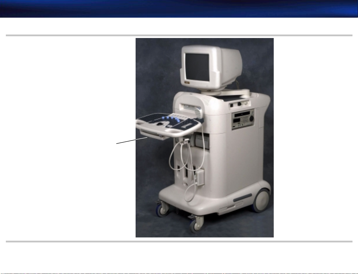
The HDI 4000 system (Figure 1-1 through Figure 1-4) is a general-purpose, mobile, software-controlled, diagnostic ultrasound system.
The HDI 4000 system uses a personal computer (PC) platform with a Windows 2000 Professional operating system and digital broadband bea mforming to provide high-resolution, high-penetration ultrasound imaging.
The HDI 4000 system uses linear array, convex arra y, phased array, static and, volume scanheads
to perform all major clinical applications. The standard operating modes are 2D/gray scale,
M-mode, color M-mode, color Doppler , Color P ow er Angio® (CPA) imaging, pulsed-wave (PW)
Doppler, steered continuous-wave (CW) Doppler, static CW Doppler , Tissue Harmonic Imaging,
Pulse Inversion Harmonic Imaging and tri-plex mode simultaneous. Volume 3D imaging mode is
optional.
The system can store up to 40,000 images (depending on har d disk dri v e installed and imag e file
size) and recall them. Data can be exported to a removable disk and transferred to the PC environment in either JPEG or BMP formats. High-density removable media capability is standard,
and the system supports compatible ink-jet printers.
The HDI 4000 system has an online Help feature. Help displays instructions for use of the HDI
4000 system on-screen, by pressing the ? button on the control panel.
Page 22
4730-0037-02 HDI 4000 Field Service Manual Page 22
General Information: System Overview
Figure 1-1 HDI 4000 Ultrasound System
Pull-out keyboard
See Figure 1-3
Page 23
4730-0037-02 HDI 4000 Field Service Manual Page 23
General Information: System Overview
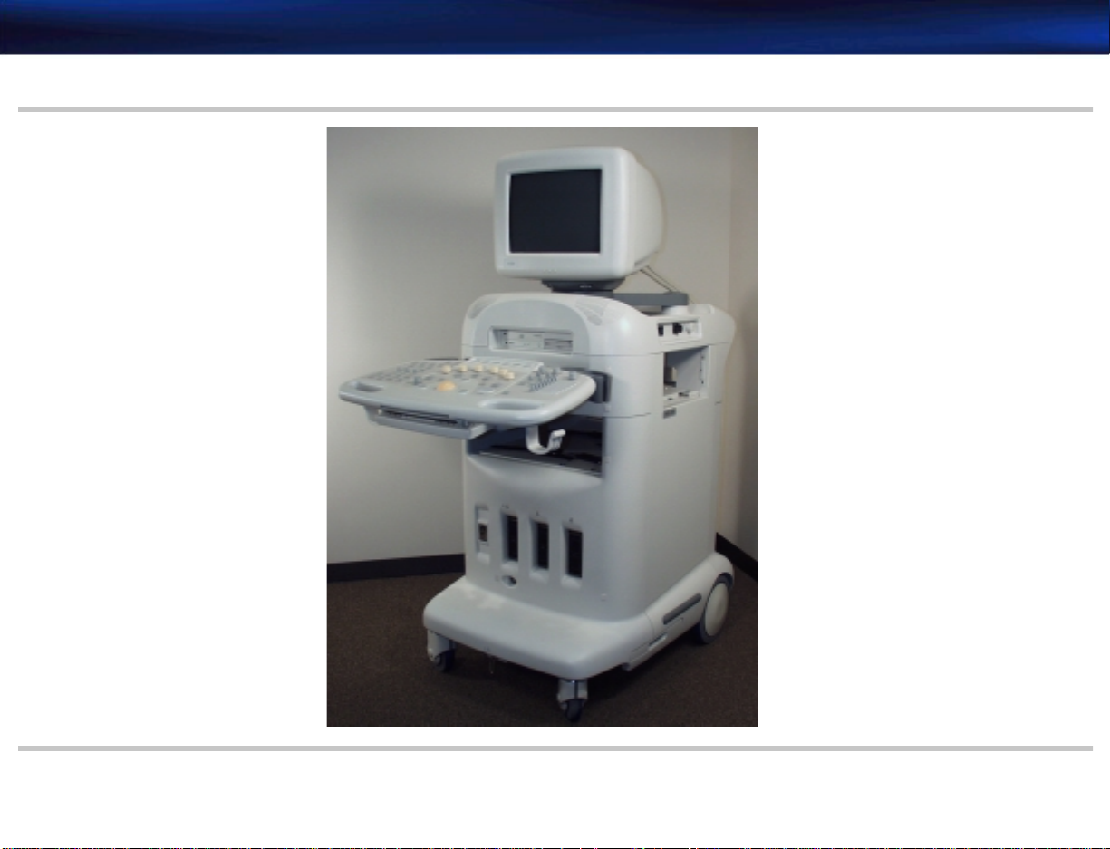
Figure 1-2 HDI 4000 Ultrasound System (Philips Colors)
Page 24
4730-0037-02 HDI 4000 Field Service Manual Page 24
General Information: System Overview
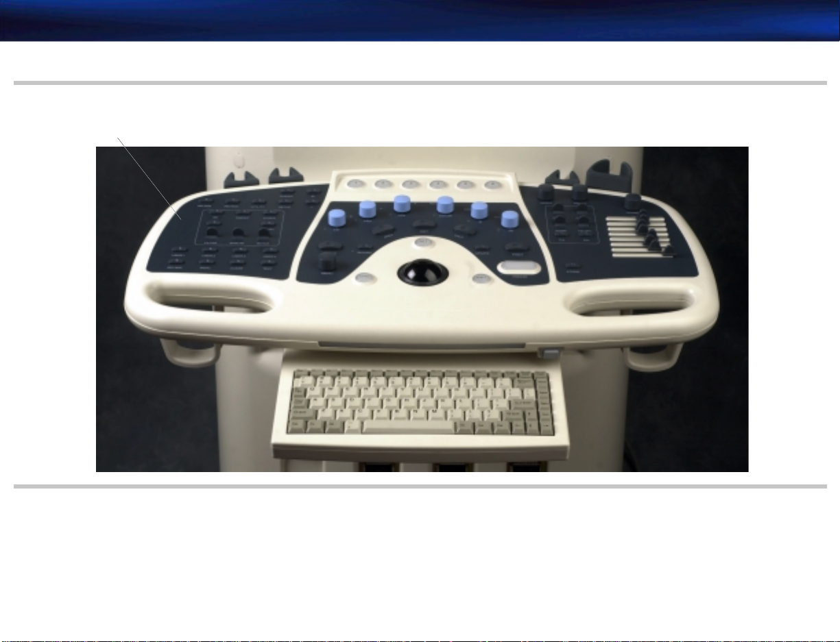
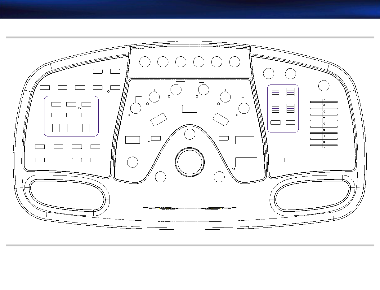
Figure 1-3 Control Panel and Pull-out Keyboard
Overla y
See Figure 1-5
Page 25
4730-0037-02 HDI 4000 Field Service Manual Page 25
General Information: System Overview
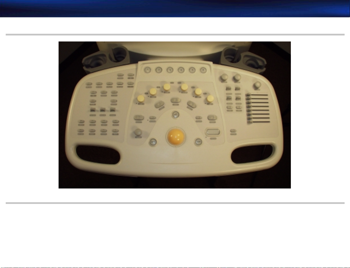
Figure 1-4 Control Panel (Philips Colors)
Page 26
4730-0037-02 HDI 4000 Field Service Manual Page 26
General Information: System Overview
Figure 1-5 Control Panel Labeling (English)
END EXAM
REVIEW SETUP
3D
DUAL
FILTER
USER2USER1
BODY MARK
INDIC.
See Figure 14-10
SWEEP
BASELINE
USER3
UTILITY
SCANHEAD ID
STEER
INVERT
SCALE
USER4
TEXTCLEAR
3
2
1
?
SELECT
MENU
X
X
CW
Y
CPA
PWD
AREA
RECORD
CHG.
4
Z
RECT.L
MAG
Y
COLOR
DIST.
CALC.
SET
5
UPDATE
EXIT
6
DEPTH
ZOOM
THI
VOLUME
POWER
FOCAL POS
TSI OPT.
PIH
STORE
ANGLE
TH.L
M
2D
PRINT
FREEZE
Page 27

4730-0037-02 HDI 4000 Field Service Manual Page 27
General Information: A pplications
Applications
• Abdominal
• Breast
• Cardiac
• Cardiac TEE
• Carotid
• Fetal Echo
• General
• GYN
• Intra-Operative
• Musculoskeletal
• Neo-natal Head
• OB
• Pediatric
• Pediatric Abdomen
• Pediatric Cardiology
• Prostate
• Renal
• Small Parts
• Trans-Cranial Doppler (TCD)
• Vascular
• Venous
Page 28

4730-0037-02 HDI 4000 Field Service Manual Page 28
General Informa t ion: Fe at ur e s
Features
Electrical Standard
• 120 Vac, 60 Hz
• 240 Vac, 50 and 60 Hz
Languages
• English
• French
• German
• Italian
• Spanish
Scanhead Selection
• Four scanhead receptacles
• Electronic switching between scanheads
Imaging Modes
• Real-time 2D gray-scale imaging
• Motion mode (M-mode)
• Color Doppler Imaging
• Color Power Angio Imaging
• Pulsed-wave (PW) Doppler
• Continuous-wave (CW) Doppler (steered and static)
Page 29

4730-0037-02 HDI 4000 Field Service Manual Page 29
General Informa t ion: Fe at ur e s
• Tissue Harmonic Imaging (Cardiac and General applications only for P4-2, P5-3, and MPT7-4
prior to v1.01.00.063 software and L7-4, C5-2, C7-4, 3D5-3, 3D7-4, CL15-7, P4-2, P5-3,
P7-4, and MPT7-4 for v1.01.00.063 and higher software)
• Pulse Inversion Harmonic Imaging 2D real-time and 3D (P7-4 Pediatrics and General; P5-3
Cardiac and General; P4-2 Cardiac, General, and Contrast (Contrast is v1.01.00.063 and
higher software); MPTEE all applications; and for v1.01.00.063 and higher software, C5-2
General, Abdominal, Renal, Abdomen, and Contrast; 3D5-3 all applications; and 3D7-4 all
applications)
• 1.01.00.063 and higher software, Contrast Specific Imaging (CSI) application is available for
the C5-2 and P4-2
Image Presentation
• Top/Bottom
• Left/Right
• Dual side-by-side
Image Processing
• Depth control
• View Area control
• Direction (Left & Right) control
• Apex (Up & Down) control
• Zoom control
• Focus (positio n & number ) control
• Reject Level selection
Page 30

4730-0037-02 HDI 4000 Field Service Manual Page 30
General Informa t ion: Fe at ur e s
• Gain control
• Dynamic Range control
• TGC Value adjustment
• Power control
• Persistence control
• Capture control
• Tag control
• Histogram utility
• 3D controls
Image Storage and Retrieval
• 256-frame Cine review memory
• Save images to and retrieve and view images from the system hard disk (in proprietary for-
mat)
• Copy images to the MO disk (in BMP or JPEG format) or to the CD-R/W disk (in BMP or
DICOM format, depending on the operation). Images can be backed up in a DICOM or 3D
format or exported in JPEG, TIF, or BMP format).
Backup and Export to CD-RW and CD-R
With v1.01.00.063 and higher software, you can reuse CD-RW (rewritable) and CD-R (recordable) disks for backup and export operations if the disk has sufficient disk space left. This allows
you to continue to add images and studies to a CD-RW or CD-R without reformatting and
deleting information from the disk.
Page 31

4730-0037-02 HDI 4000 Field Service Manual Page 31
General Informa t ion: Fe at ur e s
Measurements
• 2D mode: Distance, Angle, Area, Ellipse, Circumference, Volume.
• Doppler: Velocity, Pressure, Acceleration.
• M-mode: Time, Slope, Distance .
• Pre-measurement calibration of VCR images from HDI 4000 system.
• The images stored to Revie w can be r ecalled and measur ed for both dis tance and ar ea. These
measurements cannot be transferred to any of the analysis packages, but the measurements
can be recorded to hard copy.
Calculations
• Automatic measurement of various parameters
• Obstetrical analysis in 2D
• GYN
• Cardiology
• Vascular
• Standard Gestational Age tables
• Standard OB tables
• User-defined OB tables
DICOM
• Modality worklist
• Simultaneous network print and store
Page 32

4730-0037-02 HDI 4000 Field Service Manual Page 32
General Information: Scanheads Supported
Open Line Transfer
Open line serial data transfers of OB patient r eport to off-line printers, computers, and w orkstations (the data is sent to and appears on a computer monitor or prints on a serial printer).
On-System User Instructions (Online Help)
An online Help feature provides instructions for use of the HDI 4000 system, on-screen, by
pressing the ? button on the control panel.
Scanheads Supported
• Linear array
- L7-4
- L12-5 38 mm/50 mm
- CL15-7
• Curved array
- C5-2
- C7-4
- C8-4v
- C9-5
- C8-5
• Phased array
- P4-2
- P7-4
- P5-3
- MPT7-4
Page 33

4730-0037-02 HDI 4000 Field Service Manual Page 33
General Information: Peripherals
• Dual Element Pencil Scanhead
- D2 CW
- D5 CW
• Volume Scanhead
- 3D5-3
- 3D7-4
- 3D8-5v
Peripherals
CAUTION To av oid damaging the Son y UP-21 Printer, if the need arises, be sure to secure the thermal print-
Physical Description
• Panasonic AG-MD835 Video Cassette Recorder (purchase option - Figure 1-6)
• Sony UP-895MD Black and White Video Page Printer (purchase option - Figure 1-6)
• Mitsubishi CP800 Color Video Page Printer (purchase option - Figure 1-6)
• Sony UP-21MD Color Video Page Printer (purchase option - Figure 1-6)
ing head before shipping as described in “To secur e the Son y UP-21 print head f or transport:” on
page 182.
System Components
• Primary printed circuit boards (PCBs):
- Probe Select Assembly (PSA)
- Beamformer (BF)
- Continuous Wave Doppler Processor (CW)
- Digital Scan Converter (DSC)
Page 34

4730-0037-02 HDI 4000 Field Service Manual Page 34
General Information: Safety Requirements
- Digital Signal Processor (DSP)
- Video Manager (VM)
- Backplane (ultrasound motherboard)
- PC Motherboard
-ECG
• System operating software
• Mobile cart/system housing
- Color VGA monitor with tilt/swivel base
- Main chassis (supports the monitor, control panel, disk drives, scanhead connectors,
cable management system, and storage areas)
- Control panel and pull-out keyboard
- I/O connection panel
Safety Requirements
HDI 4000 complies with the requirements for the International Electrotechnical Commission
(IEC), Canadian Standard Association (CSA), and Underwriters Laboratories (UL).
• IEC 60601-1
• CSA22.2 No. 601.1
• UL 2601-1
Page 35

4730-0037-02 HDI 4000 Field Service Manual Page 35
General Information: Safety Requirements
Figure 1-6 HDI 4000 System Peripherals
- UP-895MD Sony Video Graphic Printer -
- UP-21MD Sony Color Video Printer -
(Black and White)
- CP800 Mitsubishi Color Printer -
- AG-MD835 Video Cassette Recorder -
Page 36

4730-0037-02 HDI 4000 Field Service Manual Page 36
General Information: Supp lies and Accesso ries
Supplies and Accessories
Philips product-specific and general purpose supplies and accessories, including scanhead biopsy
guides, are a va ilable fr om CIVCO Medica l Instruments at the ad dr esses a nd numbers belo w. Supplies and accessories are no longer available from Philips.
CIVCO Medical Instruments
102 First St. South
Kalona, IA 52247-9589
Phone: (800) 445-6741, Ex. 1 for Customer Service (USA)
(319) 656-4447 (International)
Fax: (877) 329-2482 (USA)
(319) 656-4451 (International)
E-mail: info@civcomedical.com
Internet: www.ultrasoundsupplies.com
Page 37

4730-0037-02 HDI 4000 Field Service Manual Page 37
Specifications: Introduction
2 Specifications
Introduction
System Specifications
Table 2-1 HDI 4000 System Physical Specifications and Limits
Parameter Value
Height 1492 mm (58.7 in)
Width 692 mm (27.2 in)
Depth 1115 mm (43.9 in)
This section summarizes the system specifications for the HDI 4000 Ultrasound System. Scanhead specifications are provided in Section 15, “Scanheads”.
The configuration of the computer platform is as follows:
• PC with Intel processor
• 512 MB main memory
• 40 GB HDD (may be a 20-GB HDD in earlier systems)
• MO drive
• CD-R/W drive
• Sound/LAN/VGA capa bilities
• PC Interface for ultrasound module interface
Weight without peripherals approximately 166 kg (365 lbs)
Ambient Operational Temperature 10°C to 40°C (50°F to 104°F)
Operational Relative Humidity 15% to 95% RH (non-condensing)
Page 38

4730-0037-02 HDI 4000 Field Service Manual Page 38
Specifications: System Specifications
Table 2-1 HDI 4000 System Physical Specifications and Limits (Continued)
Parameter Value
Storage and Shipping Temperature -25°C to 65°C (-13°F to 149°F)
Storage Relative Humidity 20%-95%
1. Atmospheric pressure (Storage) at 1,060 hPa to 500 hPa (375–795 mmHg).
2. Atmospheric pressu re (Operating) at 1,060 hPa to 700 hPa (525
–795 mmHg).
Table 2-2 HDI 4000 System Electrical Power Specifications
Parameter Value
Hot/Neutral 90-132 Vac (RMS) at 50 or 60 Hz + 3 Hz
180-264 Vac (RMS) at 50 or 60 Hz + 3 Hz
Current Draw (rated)
1
10 A (at 100–120 Vac)
5 A (at 200–240 Va c)
Current Draw (measured) 6.79 A (at 120 Vac)
3.50 A (at 240 Vac)
Power Draw (measured) 811 VA (at 120 Vac)
840 VA (at 240 Vac)
Source < 48 A
Thermal Load
1
Approximately 2,550 BTU
Power Dissipation1, maximum 763 W (at 120 Vac)
775 W (at 240 Vac)
Chassis leakage current 100-240V systems 500µA max
Page 39

4730-0037-02 HDI 4000 Field Service Manual Page 39
Specifications: Wiring Sp ecification
Table 2-2 HDI 4000 System Electrical Power Specifications (Continued)
Parameter Value
Dielectric withstand voltage (DWV) between
isolation transformer primary and secondary
DWV between AC mains and exposed conductive
parts (chassis)
DWV between patient applied parts and AC mains 4000V
1. Includes the effect of peripherals operating at their maximum normal condition (for example, recording or printing).
Table 2-3 Temperature/Humidity limit
Storage/Shipping Operating Environment
High Temperature 65°C40°C
Low Temperature -25°C10°C
Non-condensing relative humidity 20%–95% 15%–95%
Wiring Specification
The electrical feed to the system shall be a dedicated line (no other equipment on the same line)
with a third-wire ground. The ground wire shall be an insulated solid copper conductor bonded
to the ground bus of the service panel. The outlet shall be a Hospital Grade Receptacle or an
Isolated Ground Receptacle. Pr oper inst allation sha ll reflect compliance with the nati onal electrical code or the appropriate governing body.
4000V
1500V
Page 40

4730-0037-02 HDI 4000 Field Service Manual Page 40
Safety: Introduc tion
3Safety
Introduction
Safety
Information
This section summarizes the safety information for the HDI 4000 Ultrasound System.
Please read this information before using or servicing a Philips ultrasound system. It
applies to the ultrasound system, scanheads, recording devices, and any optional equipment.
This device is intended for use by, or by the order of, and under the supervision of a licensed
physician qualified to direct the use of the device.
In this manual, WARNING is used to indicate the presence of a hazard that can cause personal
injury, death, or substantial property damage if the warning is ignored.
In this manual, CAUTION is used to indicate the presence of a hazard that can cause equip-
ment damage if the caution is ignored.
In this manual, NOTE is used when additional comment or explanation is required about instal-
lation, operation, or maintenance information that is important but not hazard-related.
Page 41

4730-0037-02 HDI 4000 Field Service Manual Page 41
Safety: Safety Information
Mechanical Safety
WARNINGS • The system is heavy, be careful when moving it, especially going up and down stairs. Nor-
mally, as many as four adults are required to move the system manually on stairs.
• Philips recommends pushing the system, instead of pulling it, and exercising special caution
when going up or down ramps.
• Unlock the front wheel brake before attempting to move the system.
Electrical Safety
This equipment has been certified by a recognized third-party testing agency as a Class I device
with Type BF isolated patient-applied parts. For maximum safety observe these warnings:
WARNINGS • Before connecting and applying power, any mounting screws that complete the system
ground path must be in place and properly secured.
• Shock hazards ma y exist if this sy stem is not pr operl y gr ounded. Protection against electrical
shock is provided by gr ounding the chassis with a 3-wire cable and plug. The system must be
plugged into a hospital-grade three-prong outlet. The grounding wire must not be removed
or defeated.
• Hazardous voltages are present inside the system. Cabinet panels must be in place while the
system is in use. All internal adjustments and replacements must be made by a qualified Philips field service engineer
Page 42

4730-0037-02 HDI 4000 Field Service Manual Page 42
Safety: Safety Information
WARNINGS • Do not opera te this system in the presence of flammable gases or anesthetics. Explosion can
result.
• Always inspect the scanhead face, housing, and cable before use. Do not use the scanhead if
the face is cracked, chipped, or torn, if the housing is damaged, or if the cable is abraded.
• Always turn the system power off and disconnect it fr om the wall outlet prior to cleaning the
system.
• Connection of optional devices not supplied by Philips could result in electrical shock. When
such optional devices are connected to your ultrasound system, ensure that the total system
chassis risk current does not exceed 100 µA for 120 Vac systems and 500 µA for 230 Vac
systems.
• In general, only the area of the scanhead acoustic window is watertight. Except where speci-
fied in specific scanhead cleaning instructions, do not immerse the r emainder of a scanhead in
any liquid.
CAUTIONS • This equipment contains components that are electrostatic sensitive. Proper anti-static pro-
cedures, protection, and equipment must be used prior to opening and during handling of
this equipment. Failure to use ESD pr ocedur es will d amage the c omponents. Such da mage to
components is not covered by Philips warranties.
• Do not connect or disconnect scanheads without first placing system in FREEZE mode.
• Damage to the system may occur if the system power is incorrectly configured and the sys-
tem is connected to an improper power source.
Page 43

4730-0037-02 HDI 4000 Field Service Manual Page 43
Safety: Safety Sym bols
CAUTIONS • Damage to a peripheral may occur if the OEM power is incor rectly configured and the OEM
is connected to an improper power source.
• Always turn the power off and wait at least 30 seconds before removing or installing any
PCB, module, or component.
Safety Symbols
The International Electrotechnical Commission (IEC) has established a set of symbols for medical
electronic equipment, which classify connections or warn of any potential hazards. The classifications and symbols are shown below.
Isolated patient connection (IEC 601-1-Type BF)
Footswitch
I and O on power switch represent ON and OFF, respectively.
This symbol identifies a safety note. Ensure you understand the
function of this control before using it. Control function is
described in the unit’s operation manual.
Page 44

4730-0037-02 HDI 4000 Field Service Manual Page 44
Safety: Safety Sym bols
Identifies equipotent ground (located next to ground stud on the
rear panel) (IEC 417-5021).
Identifies high voltage components operating above 1000 Vac or
1500 Vdc.
Identifies the point where the system safety ground is fastened to
the chassis.
VGA or PARALLEL Output port
RS232C or LINE/USB/DICOM Input/Output port
AUDIO Left/Right, VHS/S-VHS, MIC, or DVD Input port
AUDIO Left/Right, VHS/S-VHS, Output port
VIDEO PATIENT MONITOR, B/W PRINTER or INTERLAC E RGB
Output port
Page 45

4730-0037-02 HDI 4000 Field Service Manual Page 45
Safety: Safety Sym bols
PRINT REMOTE Output
ECG Connection
Watertight equipment
IP
Drip-proof equipment
IP
Scanhead Connection
Pencil Probe Connection
Page 46

4730-0037-02 HDI 4000 Field Service Manual Page 46
Theory of Operation: Introduction
4 Theory of Operation
Introduction
System
Architecture
This section provides a functional description of the HDI 4000 Ultrasound System.
The HDI 4000 system architecture is made up of six fundamental functional elements:
• Physical assemblies comprising the mobile cart and system components
• Power functions
• Control functions
• Ultrasound signal generation and echo acquisition functions
• Signal and image data processing and analysis functions
• Visual and audio presentation functions
The location and identification of the physical parts of the system are described in the General
Information, Cabling, Configuration, and Parts sections of this document. The functional nature
of each is described in the following paragraphs.
System power development and distribution is provided by the installation site source voltage,
the system power supply, the backplane power bus, and power interconnect cables (see “Oper-
ating Power” on page 50).
The control, acquisition, processing, and presentation elements of the system architecture are
supported by a Pentium processor computer platform that pr ovides a real-time operating system
with hardware and software interfaces to the disk drives, control panel, and peripherals. This
platform is combined with ultrasound electronics which include a digital beamformer and ultrasound software.
The HDI 4000 system ultrasound engine is physically and functionally made up of the Industrial
PC Motherboard (Motherboard), four digital Beamformer (BF0-BF3) PCBs, Continuous Wave
Page 47

4730-0037-02 HDI 4000 Field Service Manual Page 47
Theory of Operation: Operating System
Doppler Processor (CW) PCB, Digital Signal Processors (DSP) PCB, Digital Scan Converter
(DSC) PCB, and Video Manager (VM) PCB. Most of the ultrasound signal processing, image pro-
cessing, analysis, and display functions are performed by software using the native processing
power of the computer (Industrial PC Motherboard).
Operating System
The full-service, real-time Windows 2000 operating system provides an integrated range of
resources: drivers and handlers for storage, video, serial and parallel ports, and support of file
system services and graphical user interfaces. The operating system, based on a Pentium processor, is resident on the hard drive. The system software performs these tasks:
• Processes requests from the control panel
• Sets up beamforming parameters
• Processes acquired ultrasound echoes into digital visual representations for conversion into
analog signals
• Performs measurements and calculations on acquired data
• Stores acquired data (such as images and user-entered data) for subsequent retrieval
• Performs all necessary functions to coordinate software tasks
Page 48

4730-0037-02 HDI 4000 Field Service Manual Page 48
Theory of Operation: Functional Description
Functional Description
The HDI 4000 system produces 2D, M-mode, color Doppler, color power angio, Doppler, and
3D ultrasound images using transducers (scanheads), digital beamforming, and Doppler processing. The central processing unit of the system is the Industrial PC Motherboard. The ultrasound
components comprise digital beamformer technology that combines with the operating system
to support the system functions.
The HDI 4000 system stores the ultrasound images and patient data on the hard drive and can
copy that data to the removable media, such as magneto-optical (MO) disks and CD-R/W disks
for off-line revie w . The sys tem can send the images to a black-and-white printer, color printer, or
to a VCR. It also generates reports that can be printed.
After operating power is a ppl ied, the major functional elemen ts combine to produce ultrasound
images. The user interface allows system contro l and viewing of the re sults. Figure 4-1 is a simpli-
fied block diagram of the HDI 4000 system, showing the relationship among those major functional elements and indicating the primary functional tasks performed by each. The diagram
organizes the functional elements as they exist on the system hardware.
The overall system functional flow is power development and distribution, analog signal processing, beamforming, continuous-wave and color Doppler processing, scan conversion, digital signal
processing, and video and audio presentation. Figure 4-13 is a diagram of the system 2D,
M-mode, Doppler, and color data paths.
Page 49

4730-0037-02 HDI 4000 Field Service Manual Page 49
Theory of Operation: Functional Description
Figure 4-1 HDI 4000 System Functional Block Diagram
System monitor
&
Probe Select Assembly (PSA)
- 3 Probe connectors
- Probe detection
- Probe ID
- Switching relays (128)
- Static CW connector
Beamformer PCB #3
- BF control logic
- Transmit pulse generation (16 dual pulsers)
- TGC amplification (8 dual TGC amplifiers)
- A/D conversion (16, 8bit)
- Summation of echo data
Beamformer PCB #2
Beamformer PCB #1
Beamformer PCB #0
Scanhead ID
Scanhead select
Motor drive/control
CW PCB
- Generates control data for HV mux ICs in L12-5 scanhead
- Transmit generation for Steered CW (16 channel)
- Transmit generation for Static CW
- Steered CW receive BF (16 channel)
- Static CW pre-amplifier
- Performs quadrature demodulation
- Baseband filtering on forward & reverse flow
- A/D conversion
- Send I, Q to DSP
- Generates BF master clock (61.6 MHz)
- Transmit power control
- Motor controller PCB path for 3D scanhead
ECG PCB
- ECG isolation amplifier
- ECG gain control
Digital Signal Processor (DSP) PCB
- Performs quadrature demodulation and low-pass filtering
B/W, C,
- Generates I/Q for Spectral and color Doppler processing
ECG
- Log-compression and envelope detection
- Gain and dynamic range setting
- Send grayscale data to DSC
- Performs wall filtering and FFT for Spectral Doppler
- Send Spectral data to DSC
- Performs Hilbert transform for Doppler audio
- Sends Doppler audio to VM
- Performs wall filtering and mean velocity estimation for color
Doppler processing
- Performs post-processing for color Doppler
- Send color Doppler data to DSC
- Generates analog TGC data for beamformer PCBs
ta
a
) d
, D
, M
D
(2
le
a
c
s
y
a
r
G
CW I/Q data
Digital Scan Converter (DSC) PCB
- Generates all major control signals
- Performs real time control
- A/D conversion for ECG
- Cine-loop memory
- Performs azimuth & axial color only
- Writes data In acquisition timing Into frame memory
- Generates dot clock
- Reads data In TV timing from frame memory
- Real time data generation
- Read zoom & 2D filter (edge enhancement)
- Add live 3D path
Doppler audio
ta
a
d
r
lo
o
C
- Decodes CV and Y/C to RGB
- Image grabber
- Interlace and non-interlace video output
- Digital encoding (RGB to Y/C and CV)
- Stress echo (video capture)
- Digital video
- Video color keying
- Doppler audio processing
B/W, C, ECG
- Microphone control
- Image & stress echo DMA control
Motor Controller PCB (Option)
- Motor drive for 3D volume SH
- Position sensing for 3D volume SH
a
t
a
d
A
G
V
Industrial PC (PC) PCB
- Pentium III processor, 700 MHz
- 512 MB RAM
- FD controller
- EIDE controller
- SVGA controller (C&T68030)
- Ethernet controller (RTL8139)
- Control logic
- Real time clock
- USB port
- Sound card
- Interfaces PC and digital system
- Generates power down
Video Manager (VM) PCB
3D Live Data
HDD
20 GB
Primary master
CD-R/W
Secondary
master
1.3 GB
Secondary slave
MOD
Rear Panel I/O PCBs
1. Rear panel left
- audio amplifier
2. Rear panel middle
3. Rear panel right
Control Panel
- Mode switches
- Trackball
- Encoders
- TGC slidepots
Alphanumeric Keyboard
peripherals
System
speaker
Computer bus
Control bus
Data bus
Page 50

4730-0037-02 HDI 4000 Field Service Manual Page 50
Theory of Operation: Functional Description
Operating Power
The AC power source voltage connects directly to the system power supply, which also comprises the rear panel. The pow er suppl y is c onfigured for 115 or 230 Vac operation. (see “Setting
Up the System” on page 96). A system power distribution diagram is shown in Figure 11-2. The
power supply output voltages are listed in Table 4-1. Figure 4-2 is a simple schematic diagram of
the power supply.
Table 4-1 Power Supply Output Voltages
Voltage Use
+3.3 Vdc Computer, Digital Logic, Beamformer
+5 Vdc Computer, Hard Drive, MO Drive, CDR Drive, Digital Logic,
Beamformer, Keyboard
-5 Vdc Computer, Beamformer
+12.2 Vdc Computer, Hard Drive, MO Drive, CDR Drive, Digital Logic,
Beamformer, Rear Panel, Fan
-12.2 Vdc Computer, Digital Logic, Rear Panel, PSA
+10 to 80 Vdc (+HV) Beamformer
-10 to 80 Vdc (+HV) Beamformer
0~5 Vdc Acoustic power control
Page 51

4730-0037-02 HDI 4000 Field Service Manual Page 51
Theory of Operation: Functional Description
Figure 4-2 Power Supply Schematic Diagram
VOLTAGE
SELECTOR
OUTPUT
220
S3
3
2
1
110
220
3
2
1
110
CR3
ACOUTPUT1-1
ACOUTPUT1-2
CR4
ACOUTPUT2-1
MONITOR
110 220
VCR 120
ACOUTPUT2-2
INLET
ACINPUT
ACINPUT
CR1
MAIN TRANS
T1
110
0
AC 19V
AC 19V
110
0
AC 19V
AC 19V
AC 15V
AC 15V
AC
AC
CN107
FG
PRINTER
EI70
L1
CR2
1 2
FG
1 2
VOLTAGE
SELECTOR
INPUT
110V
220V
110V
220V
S2
3
2
1
3
2
1
SW2
SW1SW1
POWER
SW
SW2
CN106
T2
110
0
110
0
OFF TIME
CONTROL
IN OVP
OUT OVP
In12
In02
I11
I01
15V
0.2A
SIGNAL
UR-OFF
Out12
Out02
Out11
Out01
SIGNAL
AC INPUT
SIGNAL
DC PC OUTPUT
-
+5VP
+3.3V
+3.3V
+5VPC
P/B P/O
+5VPC
GND GND GNDGND GND GNDGND GND GND
CN103
+12VP
C
VPC
VPC
POWER
12VP
GOOD
-5VPC
SIGNAL
C
C
AC INPUT
UR-2000D
DC DIGITAL OUTPUT
+12V
-12VD
GND
+12V
-12VD
GND
CN105 CN104
GND
+5VD
GND
D
+5VD
GND
GND
D
+3.3VD
+3.3VD
+5VD
+5VD
AVC
E1225B12H(IIC)
+3.3BF
GND
+3.3BF
GND
+3.3BF
+3.3BF
GND
GND
GND
GND
SIGNAL
AC INPUT
FAN
UR-2000A
HV IN/OUT
ANALOG OUTPUT
+5VAGND
GND
GND
GND
-5VA GND
+12VA
+12VA
GND
GND
-12VA
-12VA
GND-5VA+5VA
-97V
GNDGND
NC
-HV
GND GND GND FANGNDGND
NC
CN101CN102
GND
+5VA +97V +HV
-5VA
HVC
Page 52

4730-0037-02 HDI 4000 Field Service Manual Page 52
Theory of Operation: Functional Description
Probe Select Assembly (PSA)
Figure 4-3 is a simple block diagram of the Probe Select Assembly, which provides the function of
a scanhead select module. The PSA is the system interface for thr ee s canheads and the CW pencil probe (“General Information” on page 21 and “Scanheads” on page 303). It contains circuits
for scanhead detection and identification, engaging the appropriate number of relays to accommodate transmitting and receiving pulses and echoes. The PSA has three 260-pin Cannon connectors and one coax-pin Lemo connector. Figure 4-4 shows the pin grid for the Cannon
connector and Figure 4-5 the pin layout for the Lemo connector.
The PSA receives high-v oltage pulse signals from the Beamformer PCBs [Beamformer (BF0-BF3)]
and switches them through analog relays as inputs to the active scanhead to generate the ultrasound signal. The returning echoes ar e passed through these relays and back to the Beamf ormer
PCBs for processing. Scanhead ID, scanhead select, and motor drive/control data is exchanged
with the Continuous Wave Doppler Processor (CW) PCB.
Page 53

4730-0037-02 HDI 4000 Field Service Manual Page 53
Theory of Operation: Functional Description
Figure 4-3 Probe Select Assembly Block Diagram
Universal
HDI S/H
Connector 1
Universal
HDI S/H
Connector 2
Universal
HDI S/H
Connector 3
Static CW
Connector
128
128
128
128
Latching
Relays
Connectivity
Sensor
4
4
4
Probe ID
Steered CW TX (El. 36-51)
16
Steered CW RX (El. 14-29)
16
Relay
Control
Probe Select
No Probe
Probe ID
from/to
BF Boards
from/to
CW Board
from CW Board
to CW Board
2 Static CW TX/RX
from/to
CW Board
Page 54

4730-0037-02 HDI 4000 Field Service Manual Page 54
Theory of Operation: Functional Description
Figure 4-4 Cannon Scanhead Connector Pin Grid
Page 55

4730-0037-02 HDI 4000 Field Service Manual Page 55
Theory of Operation: Functional Description
Figure 4-5 Lemo Connector Pin Layout
C1
41
52
C2
63
Page 56

4730-0037-02 HDI 4000 Field Service Manual Page 56
Theory of Operation: Functional Description
Beamformer (BF0-BF3)
Figure 4-6 is a functional diagram of the Beamformer module, which is made up of four identical
Beamformer PCBs. The Beamformer PCBs are responsible for generating and transmitting
pulses to the scanhead elements. When the returning echoes come back into the system, they
are sent in analog form to the Beamf ormer PCBs for pr ocessing, wher e the r eturning echoes ar e
amplified using time gain compensation (TGC), and a r e filter ed p rior to be ing con v erted into digital data. Once the data is digitized, it is sent to specialized circuits that perform the beamforming.
The signal processing functions of digital beamforming that determine the real image quality of
the system include dynamic apodization, multiplication, coefficient loading, va ria ble sa mple clock
generation, summation of the channels within each board, and dynamic gain control.
Page 57
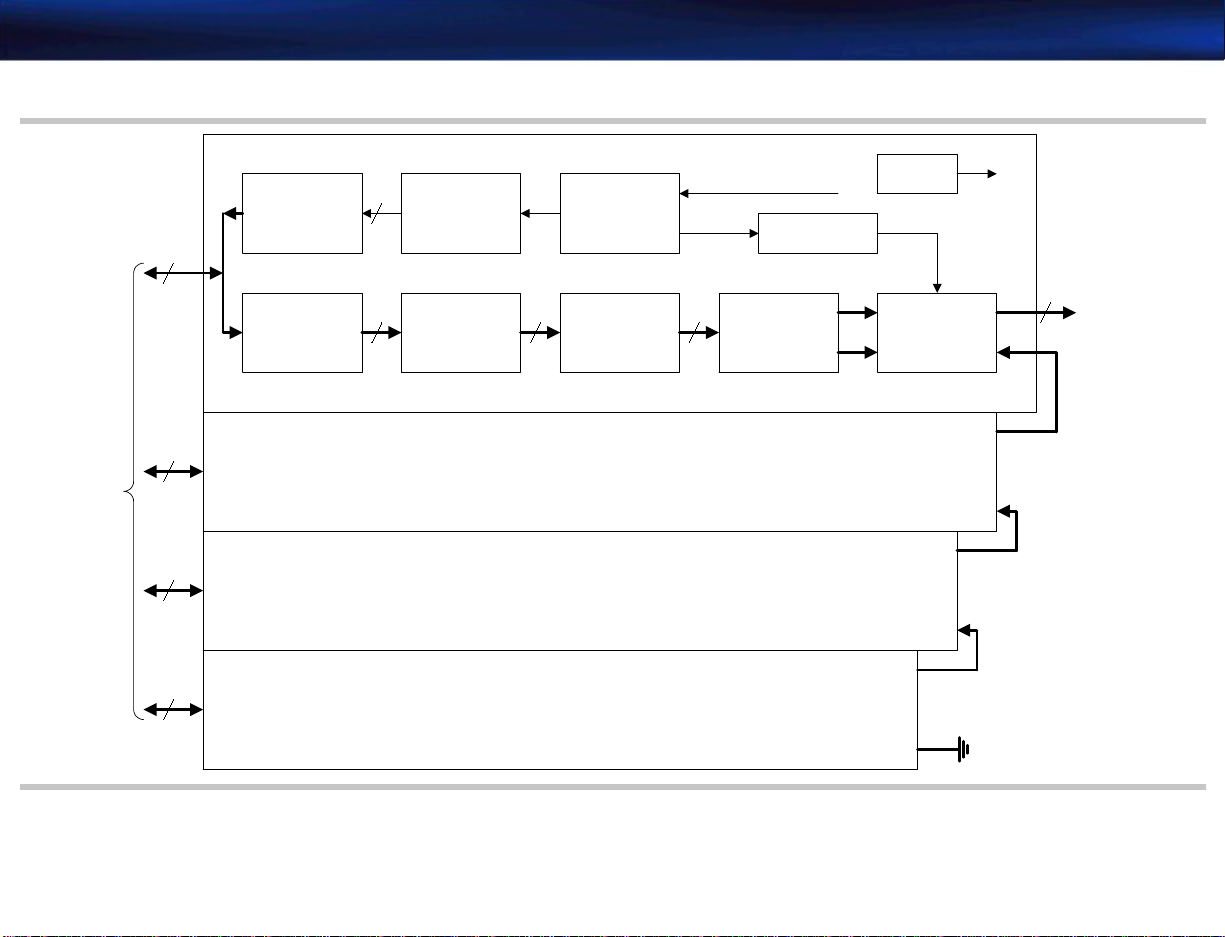
4730-0037-02 HDI 4000 Field Service Manual Page 57
Theory of Operation: Functional Description
Figure 4-6 Beamformer Block Diagram
PSA
BF Board #3
Control & Clock
Dual Pulsers
(16)
32
Limiter
(16)
BF Board #2
32
to
BF Board #1
32
BF Board #0
32
16
16 16 16
TX
ASIC
TGC Amplifier
(16)
max gain 48dB
Control
Logic
LPF
19.9 MHz
Memory
A/D Converter
(16)
Clock
Buffer
OUT
BFIC
(4)
OUT
IN
Sum 0
61.6 MHz
OUT
Sum 2
IN
Sum 1
RF Data
16
to
DSC
IN
IN
Page 58

4730-0037-02 HDI 4000 Field Service Manual Page 58
Theory of Operation: Functional Description
Continuous Wave Doppler Processor (CW)
Figure 4-7 is a functional diagram of the CW PCB.The CW PCB functions that support static
CW and steered CW are:
Static CW
• CW pulser to drive scanhead transducer
• RF pre-amplifier to receive signal
• Mixer to change from RX signal to baseband signal with 50 kHz range of right-angle phase
(0 and 90 degrees)
• Thump filter (200/2 kHz)
• Variable Wall filter (Min. 200 Hz)
• Variable gain
• Variable lowpass filter with 1 kHz resolution for noise bandwidth performance
• 16-bit analog-to-digital converters
Steered CW
• 16-channel CW pulser to drive scanhead transducer
• 16-channel RF pre-amplifier for receiving signal
• TX/RX Beamformer for focusing when transmitting and receiving
• Mixer for basebend with 50 kHz range of right-angle phase (0 and 90 degrees)
• Thump filter (200/2 kHz)
• Variable Wall filter (Min. 200 Hz)
• Variable gain
• Variable lowpass filter with 1 kHz resolution for noise bandwidth performance
• 16-bit analog-to-digital converters
Page 59

4730-0037-02 HDI 4000 Field Service Manual Page 59
Theory of Operation: Functional Description
Figure 4-7 CW Block Diagra m
Static
CW
Probe
Phased
Array
Probe
System
Interface
Tx EL.
Rx EL.
EL.
16
36~51
EL.
16
14~29
De-
Modulation
(TAK-3H)
&
L.O. Driver
Fo COS Fo SIN
Pulser
Pre-Amp
Pulser
16CH
Pre-Amp
16CH
I
Wall/
Thump
Filter
Q
CW Control
&
Probe Personality
HV MUX
Control
Fo Cos
16
16
Transmit
Receive
Variable
CW PWR
Focus
Focus
Gain
XD[0..7]
XCLK
XLD
HV+,HV-
Fo Cos
Selector
(Static or
Steered)
Nyquest
Filter
LPF
Buffer
I
16bit
ADC
Q
16bit
ADC
CW/System Clock
Generator
61.600MHz
OSC
Probe Select Assembly Control
Notch
Filter
(Reject
Carrier &
some
Clutter)
CW I/Q Data Interface
Fo COS
Fo SIN
8Fo
2.0MHz
Band
Pass
Filter
Relay
P-Data
SHS
Power
CW Data
CW SCLK
CW RFS
Mixer
Driver
Page 60

4730-0037-02 HDI 4000 Field Service Manual Page 60
Theory of Operation: Functional Description
Digital Signal Processors (DSP)
Figure 4-8 is a simple block diagram of the DSP PCB. The RF data from the Beamfor mer PCBs is
sent to the mid-processor via the bypass filter. While the RF data is going through the process of
filtering and demodulation, it makes 2D-mode output and in-phase/quadrature-phase (I/Q) data.
After adjusting the 2D-mode output gain, 2D-mode is output to the Digital Scan Converter
(DSC) PCB.
I/Q data from the CW PCB is received and put through signal clutter filtering, Doppler, and
audio processing. Doppler is sent to the DSC PCB and audio Doppler is sent to the Video Man-
ager (VM) PCB.
I/Q data from the mid processor i s further pr ocessed for Color Doppler image data. The Color
Doppler processor provides signal clutter filtering and velocity estimation. The Post DSP then
receives this Doppler and clutter data and carries out the process of flash artifact rejection, spatial filtering, and horizontal line interpolation before outputting the color Doppler image data to
the DSC PCB.
Page 61

4730-0037-02 HDI 4000 Field Service Manual Page 61
Theory of Operation: Functional Description
Figure 4-8 DSP Block Diagram
RF
from BF
I/Q Data
from CW
16
PRE-MID
(FPGA)
u5
16 x 2
MID
PROCESSOR
(MGA015A)
u4
I, Q
FIFO
u18/u19/
u20/u21
16 x 2
16
POST-MID
CLUTTER
DSP
(ADSP 2183)
u22
COLOR
DOPPLER
PROCESS
OR
(MGA016)
(FPGA)
u10
u71
8
FFT DSP
(ADSP 2183)
u23
AUDIO
DSP
(ADSP 2183)
u24
16 x 2 16
POST DSP
(ADSP 2183)
u27/u28/
u29/u30
2D mode
to DSC
8
Spectral Doppler
to DSC
Doppler Audio
to VM
Color Doppler
to DSC
Page 62

4730-0037-02 HDI 4000 Field Service Manual Page 62
Theory of Operation: Functional Description
Digital Scan Converter (DSC)
Backplane
Figure 4-9 is a functional diagram of the DSC PCB. Scan conversion is the process for mapping
echo information into frame memory for displa ying on the monitor. The DSC receives ECG data
processed by the ECG PCB. Grayscale (2D, M, D) data and color data is received from the DSP
for smoothing, edge enhancement, frame averaging, and line interpolation processing. The DSC
maps data to frame memory according to an algorithm and sends image data to the Video Man-
ager (VM).
The Backplane (Motherboard) is the physical and functional “backbone” of the ultrasound
engine. It is wired to the power supply (Figure 11-2) from which it receives DC operating voltages (Table 4-1) to distribute to the system components via a power bus and pow er cabling. The
Backplane also provides control and signal interconnection (Figure 11-1) between the system
components via data, computer, and control buses (Figure 4-1) and signal cabling. The Beam-
former (BF0-BF3), Continuous Wave Doppler Processor (CW), Dig ital Sig nal Processors (DSP),
Digital Scan Converter (DSC), Video Manager (VM), and Input/Output Panel PCBs are all
plugged into connectors on the Backplane (Figure 13-2 and Figure 13-3).
Page 63

4730-0037-02 HDI 4000 Field Service Manual Page 63
Theory of Operation: Functional Description
Figure 4-9 Digital Scan Converter Block Diagram
2D mode
Color
from DSP
M mode
Spectral Doppler
Color M mode
ECG
Data
Axial
Buffer
Buffer
Buffer A/D
Interpolator
Live 3D
FIFO
RTC
DSP
&
FPGA
FA
&
LUT
To PC
CINE
DSC
DSP
InputCTR
SSRAM
MISC
&
FI MUX
FM
(B,C)
LoopMemCTR
LM
Frame
Interpo
lation
Read
Zoom
Edge
Enhanc
ement
OutData
(T o VM)
FIFO
OutData
(T o VM)
FIFO
Page 64

4730-0037-02 HDI 4000 Field Service Manual Page 64
Theory of Operation: Functional Description
Video Manager (VM)
The Video Manager provides video and audio development and routing. Figure 4-10 is a simple
block diagram of the video support flow, and Figure 4-11 is a simple block diagram of the audio
support flow. The VM PCB controls:
• Decoding CV and Y/C to RGB
• Image Grabber
• Interlace and Non-Interlace Video Output
• Digital Encoding (RGB to Y/C and CV)
• Stress Echo (Video Capture)
• Digital Video
• Video Color Keying
• Doppler Audio Processing
• Microphone Control
• Image & Stress Echo DMA Control
Page 65

4730-0037-02 HDI 4000 Field Service Manual Page 65
Theory of Operation: Functional Description
Figure 4-10 VM: Video Support Block Diagram
Image
Grabber
VCR In
Video
Input
Decoder
Scan
Converter
(I --> NI)
Memory
ACQ
FIFO
Image Store --> PC
B, C In
M, D, CM In
ECG In
VGA In NI Video Out
Input
Control
Post
Map
(R, G, B)
Image
Grabber
Video
Key
Mode
Converter
(640*480 --> 800*600)
Video
DAC
Post FPGA
I/O Decoder
&
FPGA Download
CPLD
Video
Manager
DSP
NI to I FPGA
Mode
Converter
Mode
Converter
Memory
Scan
Converter
(NI --> I)
Mode
Converter
Memory
Stress Echo FPGA
Stress Echo
Image
Capture
Video
Encoder
Video
DAC
PC
VHS,
SVHS Out
RGB Out
Page 66

4730-0037-02 HDI 4000 Field Service Manual Page 66
Theory of Operation: Functional Description
Figure 4-11 VM: Audio Support Block Diagram
Doppler Audio In
PC Audio In
VCR Audio In
MIC In
16bit Serial
D/A
Converter
(AD766)
VCR Input
Buffer
Microphone
Buffer
(SSM2165)
Programable
Low Pass Filter
(S3528B)
System/VCR
Select
Switch
Buffer
AMP
Buffer
Microphone
On/Off
Switch
OP Amp &
Low Pass Filter
Volume Control
(AD7524)
Adder
Doppler
On/Off
Switch
Sound Card
Output
On/Off
Switch
Buffer
Buffer
Buffer
Adder
to Rear Panel
(Audio Amplifier)
VCR Audio Out
to Sound Card
Page 67

4730-0037-02 HDI 4000 Field Service Manual Page 67
Theory of Operation: Functional Description
Industrial PC Motherboard
The central processing unit of the system is the Industrial PC Motherboar d, a P entium proces sor
CPU that is similar to the motherboard used in a personal computer. The Industrial PC Motherboard determines system functionality and coordinates the overall communication between the
user and the system, which includes storing and saving images. The Industrial PC Motherboard
communicates continually with the hard drive for operating parameters. See Table 4-2 through
Table 4-10 for computer reference information. The Industrial PC Motherboard provides these
primary functions:
• Pentium processor
• FD controller
• EIDE controller
• SVGA controller
• Ethernet controller
• Control logic
• Real-time clock
• USB port
• Sound card
• PC and digital subsystem interface
• Generates power-down sequence on command
Page 68

4730-0037-02 HDI 4000 Field Service Manual Page 68
Theory of Operation: Functional Description
Table 4-2 System Computer Settings
Setup Menus Options
STANDARD CMOS SETUP (Table 4-3)
BIOS FEATURES SETUP (Table 4-4)
CHIP FEATURES SETUP (Table 4-5)
POWER MANAGEMENT SETUP (Table 4-6)
PNP/PCI CONFIGURATION (Table 4-7)
INTEGRATED PERIPHERALS (Table 4-8)
LOAD SETUP DEFAULTS
SUPERVISOR PASSWORD
USER PASSW ORD
IDE HDD AUTO DETECTION
SAVE & EXIT SETUP
EXIT WITHOUT SAVING
ESC: Quit ↑↓→←: Select Item
F9: Load Set Define F10:Save & Exit Setup (SHIFT)F2:Change Color
Page 69

4730-0037-02 HDI 4000 Field Service Manual Page 69
Theory of Operation: Functional Description
Table 4-3 STANDARD CMOS SETUP Settings
Date (mm:dd:yy): Thu, Dec 27 2001
Time (hh:mm:ss): 15 : 03 : 27
TYPE SIZE CYLS HEAD PRECOMP LANDZ SECTOR MODE
Primary Master: AUTO 0 0 0 0 0 0 AUTO
Primary Slave: NONE 0 0 0 0 0 0 -----Secondary Master: AUTO 0 0 0 0 0 0 AUTO
Secondary Slave: AUTO 0 0 0 0 0 0 AUTO
Drive A: NONE
Drive B: NONE
Video: LDC + CRT
Halt On: All, But Keyboard
Total Memory: 262144K
Esc: Quit ·®‡?: Select Item Pu/Pd/+/-: Modify
F1: Help (Shift) F2: Change Color
Base Memory: 640K
Extended Memory: 261120K
Other Memory: 384K
-------------------------
Page 70

4730-0037-02 HDI 4000 Field Service Manual Page 70
Theory of Operation: Functional Description
Table 4-4 BIOS FEAT URES SETUP Settings
Virus Warning
CPU Internal Cache
External Cache
CPU L2 Cache ECG Checking
Quick Power On Self Test
Boot Sequence
Swap Floppy Drive
Boot Up Floppy Seek
Boot Up Numlock Status
Gate A20 Option
Typematic Rate Setting
Typematic Rate (Chars/Sec)
Typematic Delay (Msec)
Security Option
OS Select For DRAM>64mb
Report No FDD for WIN95
Display PnP/PCI Device List
: Disabled
: Enabled
: Enabled
: Enabled
: Enabled
: C, A, SCSI
: Enabled
: Enabled
: ON
: Fast
: Enabled
: 30
: 250
: Setup
: Non-OS2
:NO
:Yes
Video BIOS
Shadow
C8000-CBFFF
Shadow
CC000-CFFF
Shadow
D0000-D3FFF
Shadow
D4000-D7FFF
Shadow
D8000-DBFFF
Shadow
DC000-DFFF
Shadow
: Enabled
: Disabled
: Disabled
: Disabled
: Disabled
: Disabled
: Disabled
Esc: Quit ·®‡?: Select Item
F1: Help Pu/Pd/+/-: Modify
F5: Old Values (Shift)F2: Color
F6: Load BIOS Defaults
F7: Load Setup Defaults
Page 71

4730-0037-02 HDI 4000 Field Service Manual Page 71
Theory of Operation: Functional Description
Table 4-5 CHIP FEATURES SETUP Settings
Auto Configuration
EDO DRAM Speed Selection
EDO CASx# NA Wait State
EDO CASx# Wait State
SDRAM RAS –to-CAS Delay
SDRAM RAS Precharge
SDRAM CAS Latency Time
SDRAM Precharge CONTROL
DRAM Data Integrity Mode
System BIOS Cacheable
Video BIOS Cacheable
Video RAM Cacheable
8 Bit I/O Recovery Time
16 Bit I/0 Recovery Time
Memory Hole At 15M-16M
Passive ReleaseDelayed
Delayed Transaction
Auto Detect DIMM CLK
: Enable
: 60 ns
: 2
: 2
: 3
: 3
: 3
: Disabled
: Non-ECC
: Disabled
: Disabled
: Disabled
: 3
: 1
: Disabled
: Enabled
: Disabled
: Enabled
Esc: Quit ·®‡?: Select Item
F1: Help Pu/Pd/+/-: Modify
F5: Old Values (Sh ift)F2: Color
F6: Load BIOS Defaults
Page 72

4730-0037-02 HDI 4000 Field Service Manual Page 72
Theory of Operation: Functional Description
Table 4-6 POWER MANAGEMENT SETUP Setting s
Power Management
PM Control by APM
Video Off Method
Video Off After
MODEM Use IRQ
Doze Mode
Standby Mode
Suspend Mode
HDD Power Down
Throttle Duty Cycle
PCI/VGA Act-Monitor
Soft-Off by PWR-BTTN
CPUFAN Off in Suspend
PowerOn by Ring
IRQ8 Break Suspend
: Disabled
: Yes
: DPNS
: Standby
: NA
: Disable
: Disable
: Disable
: Disable
: 62.5%
: Disabled
: Instand-Off
: Enabled
: Disabled
: Disabled
** Reload Global Time
IRQ[3-7,9-15],NMI
Primary IDE 0
Primary IDE 1
Secondary IDE 0
Secondary IDE 1
Floppy Disk
Serial Port
Parallel Port
Events **
: Disabled
: Disabled
: Disabled
: Disabled
: Disabled
: Disabled
: Enabled
: Disabled
Esc: Quit ↑ ↓ → ← : Select Item
F1: Help Pu/Pd/+/-: Modify
F5: Old Values (Shift)F2: Color
F6: Load BIOS Defaults
F7: Load Setup Defaults
Page 73

4730-0037-02 HDI 4000 Field Service Manual Page 73
Theory of Operation: Functional Description
Table 4-7 PNP/PCI CONFIGURATION Settings
PnP OS Installed
Reset Controlled by Data
Reset Configuration by
: No
: Disabled
: Auto
Onboard VGA IRQ
PCI DMAC IRQ
Onboard LAN IRQ
Onboard SOUND IRQ
USE IRQ
Esc: Quit ↑ ↓ → ← : Select Item
F1: Help Pu/Pd/+/-: Modify
F5: Old Values (Shift)F2: Color
F6: Load BIOS Defaults
F7: Load Setup Defaults
: Auto
: Auto
: Auto
: Auto
: Auto
Page 74

4730-0037-02 HDI 4000 Field Service Manual Page 74
Theory of Operation: Functional Description
Table 4-8 INTEGRATED PERIPHERALS Settings
IDE HDD Block Mode
On-Chip Primary PCI IDE
Primary Master PIO
Primary Slave PIO
Primary Master UDMA
Primary Slave UDMA
On-Chip Secondary PCI IDE
Secondary Master PIO
Secondary Slave PIO
Secondary Master PIO
Secondary Slave PIO
: Enabled
: Enabled
: Auto
: Auto
: Auto
: Auto
: Enabled
: Auto
: Auto
: Auto
: Auto
Onboard FDD Controller
Onboard Serial Port1
Onboard Serial Port2
Serial Port2 Mode
Onboard Serial Port3
Onboard Parallel Port
Parallel Port DMA
ECP Mode Use DMA
EPP Mode Select
USB Keyboard Support
Video Font Expansion
Esc: Quit ↑ ↓ → ← : Select Item
F1: Help Pu/Pd/+/-: Modify
F5: Old Values (Shift)F2: Color
F6: Load BIOS Defaults
F7: Load Setup Defaults
:Enabled
:3F8/IRQ4
:2F8/IRQ3
:Normal
:3E8/IRQ12
:378/IRQ7
:ECP+EPP
:3
:EPP1.9
:Disabled
:Enabled
Page 75

4730-0037-02 HDI 4000 Field Service Manual Page 75
Theory of Operation: Functional Description
Table 4-9 I/O Device Port Address Map
ADDRESS DEVICE
000-01F DMA CONTROLLER#1
020-03F INTERRUPT CPNTROLLER #1
040-05F TIMER
060-06F KEYBOARD CONTROLLER
070-07F REAL TIME CLO
080-08F INTERRUPT CONTROLLER #2
0F0 CLEAR MATH COPROCESSOR SINGAL
0C0-0DF DMA CONTROLLER #2
0F1 RESET MATH COPROCESSPR
0F8-0FF MATH COPROCES SPR
120 DISABLE WATHCDOG TIME OPERAQTION(READ)
121 ENABLE WATCHDOG TIME OPERATION(READ)
122 WATCHDOG
1F0-1F8 FIXED DISK CONTROLLER
200-207 GAME PORT
300-31F PROTOTYPE CARD
360-36F RESERVED
378-37F PARALLEL PORT
380-3F8 SDLC #2
SA0-3AF SDLC#1
Page 76

4730-0037-02 HDI 4000 Field Service Manual Page 76
Theory of Operation: Functional Description
Table 4-9 I/O Device Port Address Map (Continued)
ADDRESS DEVICE
3F0-3F7 FLOPPY DISK CONTROLLER
2F8-3FF SERIAL PORT #1(COM1)
2F8-2FF SERIAL PORT #2(COM2)
3F0 WINBOND I/O
Table 4-10 Interrupt Controller NMI Assignments
NMI Assigned to
IRQ0 SYSTEM TIMER OUTPUT
IRQ1 KEYBOARD
IRQ2 INTERRUPT REROUTING FROM
IRQ8 THROUGH IRQ15
IRQ3 SERIAL PORT #2
IRQ4 SERIAL PORT #1
IRQ5 RESERVED
IRQ6 FLOPPY DISK CONTROLLER
IRQ7 PARALLEL PORT #1
IRQ8 REAL TIME CLOCK
IRQ9 RESERVED
IRQ10 RESERVED(ONBOARD SCSI)
IRQ11 USB AND[ONBOARD NETWORK]
IRQ12 PS/2 MOUSE
Page 77

4730-0037-02 HDI 4000 Field Service Manual Page 77
Theory of Operation: Functional Description
Table 4-10 Interrupt Controller NMI Assignments (Continued)
NMI Assigned to
IRQ13 MATH COPROCESSOR
IRQ14 PRIMARY IDE CHANNEL
IRQ15 SECONDARY IDE CHANNEL
Input/Output Panel
The I/O Panel at the rear of the system (Figure 4-12) is made up of three PCBs (Figure 14-25)
that accomplish the interconnection between system components and peripheral devices.
Page 78

4730-0037-02 HDI 4000 Field Service Manual Page 78
Theory of Operation: Functional Description
Figure 4-12 Rear I/O Connector Panel
Page 79

4730-0037-02 HDI 4000 Field Service Manual Page 79
Theory of Operation: Functional Description
User Interface
Data Paths
The user interface comprises the controls, indicators, and output devices of the system.
The control panel (in conjunction with the monitor displays) is the primary operating interface
with the ultrasound system. The footswitch, with freeze and display change functions, is an
extension of the control panel.
The control panel (Figure 1-3, Figure 1-4) consists of TGC slide pot controls, trackball,
additional system control knobs and buttons, and a QWERTY keyboard. An internal interface
PCB reads all of the control inputs, determines the function that has been selected, and transmits that information to the Industrial PC Motherboard for processing.
Figure 4-13 is a diagram of the system 2D, M-mode, Doppler, and color data paths.
Page 80

4730-0037-02 HDI 4000 Field Service Manual Page 80
Theory of Operation: Functional Description
Figure 4-13 Data Path
Scanhead
Select
Assembly
32
32
32
32
BF
CW
ECG
Amplifier
CW I/Q Data
Grayscale (2D, M, D) Data
DSP DSC
Color Data
Audio
B/W, C, ECG
Overlay
Manager
VGA
Video
VGA
CPU
Rear
Panel
Boards
Control
Panel
Alphanum
eric
Keyboard
VGA
IRGB
Y/C
CVID
Y/C
CVID
Audio In
Audio Out
Speaker
Page 81

4730-0037-02 HDI 4000 Field Service Manual Page 81
Installation: Introduction
5 Installation
Introduction
PreInstallation
Evaluation
Checking Physical Access for Delivery, Installation, and Operation
This section contains pre-installation and installation information for the HDI 4000 system.
On-site installation usually consists of uncrating, unpacking, installing the monitor and accessories, checking connections, and powering up the system for a functional check. Read this section
completely before starting the installation.
Before the system is delivered, Philips recommends that you perform the following pre-installation evaluations.
➤ To check that the site is prepared for system installation
1. With the customer, evaluate site access for delivery. Consider the availability of a loading
dock, elevators, ramps, and the width of passageways and doors.
2. Verify that there is adequate space available for system uncrating and installation.
3. At each location where the system will be operated, veri fy that ther e is enough space for the
system and any external peripherals.
4. Check adjacent rooms for activity and types of equipment that might negatively affect the
Philips Ultrasound system.
NOTE Avoid placing the system in environments for operation or storage where the equip-
ment is exposed to water vapor, direct sunlight, high humidity, salty atmosphere, and
chemicals or gas.
Page 82

4730-0037-02 HDI 4000 Field Service Manual Page 82
Installation: Pre- Installation Evaluation
Checking the Operating Envir o nment
Wiring Requirements
Advise the appropriate facility representative of system environmental operating requirements,
including proper ventilation. If the r ooms wher e the system will be used seem excessiv ely hot or
humid to you, ask the facility representative to tak e meas ur ements. If the y ar e not within system
environmental operating specifications, ask the facility representative to make the appropriate
corrections.
Philips recommends that the electrical feeds to the system each be a dedicated line (no other
equipment on the same line) with a thir d-wir e gr ound. The gr ound wir e shall be an insulated, isolated solid copper conductor bonded to the ground bus of the service panel. The outlet shall be
a Hospital Grade Receptacle (for installations in North America) or an Isolated Ground Receptacle. Proper installation shall reflect compliance with the national electrical code, or the appropriate governing agency.
Checking the Electrical P o w er Source
WARNING For safety and liability reasons, do not disass emble any pow er outlet or open an y electrical panel.
Have the facility representative confirm wiring compliance with the criteria specified below.
➤ To verify a dedicated AC line
1. Explain to the facilities representative that the system requires a dedicated AC line meeting
the electrical power requirements identified in “Specifications” on page 37.
Page 83

4730-0037-02 HDI 4000 Field Service Manual Page 83
Installation: Pre- Installation Evaluation
2. Verify that the outlet to be used is a dedicated line.
a. Have the facility repr esentativ e open the cir cuit br eak er corr esponding to the A C l ine for
the system.
b. Confirm that power is still applied to all other outlets and hard-wired devices in the
immediate area and that power is removed only from the dedicated outlet.
3. Verify the proper wiring of the outlet. Also test for the presence of a ground and if equipped
to do so, try to verify that neutral and ground are not reversed.
4. Review with the facility repr es entative the current dra w of the system and the voltag e range
it requires. It is the responsibility of the facility representative to determine the proper size
of the wire based upon the length of the feed.
5. Measure the hot/neutral, hot/ground, and neutral/ground voltages with a comparable load
(for example, another ultrasound system) on the line.
6. Determine line loss.
a. Have the fac ility represen tative mea s ure the voltag e at the primary of the line's circuit
breaker in the distribution sub-panel. If a facility representative is not available go to
step c.
b. Measure the voltage at the wall outlet. Calculate the per centage of v oltage loss acr oss the
line using this formula:
Percent line loss = [(A-B)/A] x 100
where A is the voltage at the circuit breaker with the system on, and B is the voltage at
the wall outlet with the system on.
c. If a facility representa tive is not available, measure the voltage at the outlet with the load
on and then with the load off.
Page 84

4730-0037-02 HDI 4000 Field Service Manual Page 84
Installation: Pre- Installation Evaluation
d. Calculate the percentage of voltage loss across the line using this formula
Percent line loss = [(A-B)/A] x 100
where A is the voltage at the wall outlet with the system off, and B is the voltage at the
wall outlet with the system on.
7. If you are equipped and trained to do so, measure the power line noise. Repeat with a load
applied, for example, another ultrasound system.
8. Record your power quality observations and measurements.
9. Affix a Pow er Line Data stic ker to the most qualified outlet in each of the primary operating
areas. Add the circuit breaker number and location.
Checking for
Electrostatic
During system operation and maintenance, electrostatic discharge (ESD) can cause system
lock-ups, equipment reliability problems, and component failures.
Discharge
CAUTION With system covers or shields removed, ESD will always cause component damage. ESD damage
is cumulative and may not be apparent at first, as indicated by a hard failure, but can cause
degraded performance. Therefore, always use proper ESD handling procedures.
ESD results from a difference in electrical potential equalizing. ESD is more prevalent in low
humidity and when there is friction against carpeting, linen, and clothing. Avoid placing the system directly under or close to HVAC vents. While special equipment is requir ed to measur e ESD
levels, you can determine the presence of ESD as follows:
• Check for the presence of ESD by walking around where the system will be installed and
touching grounded surfaces. Note if you experience static discharges in the area.
Page 85

4730-0037-02 HDI 4000 Field Service Manual Page 85
Installation: System Installation
• Ask the operators if they have experienced static discharges in the work area.
• If ESD is evident, suggest possible ESD minimizing de vices and their usage, for example, static
mats, humidifiers, and sprays.
System Installation
Preliminary Inspection
Unpacking the System
The following paragraphs contain system installation procedures. After you have completed the
physical s ystem installation and initial s etup, verify that the system operates cor rectly using tests
from “Performance Tests” on page 119. Read this section completely before starting system
installation.
➤ To inspect the shipping crate for signs of damage
1. Inspect the shipping crate before unpacking the system, examining it for any damage. Look
for evidence that might indicate that the crate was opened.
2. Inspect tilt and shock indicators on the outside of the shipping crate to ensure that they are
not indicating RED. If the indicators show RED, the system needs to be inspected and tested
to determine if it was damaged in shipment.
3. Report any damage or pilferage to the carrier, the customer, and the Philips traffic department.
➤ To unpack the system shipping crate
1. Inspect the shipping crate before unpacking the system (Figure 5-1).
2. Ensure that you have sufficient space to unpack the system.
WARNING Use caution when removing the strapping bands securing the shipping crate. These bands are
under enough tension to cause injury if removed carelessly.
3. Remove (cut) the strapping bands from around the crate carton.
Page 86

4730-0037-02 HDI 4000 Field Service Manual Page 86
Installation: System Installation
4. Remove the carton top cover from the shipping crate.
5. Cut the taped edges of the carton, and carefully remove the carton from around the system.
NOTE Look for the label side that says, “OPEN THIS SIDE”.
6. Carefully remove the interior foam cushioning and any other packing materials (Figure 5-2).
7. Remove the monitor, hard disk drive, and accessory kit cartons from the crate and carefully
set aside.
WARNING Remove the two 9/16-inch bolts securing the front section of the inner crate to the pallet. This
piece also serves as a ramp .This system w ei ghs a ppr o xima tely 101 kg (222 lbs). To av oid possible
personal injury or damage to equipment, do not attempt to lift the system without assistance.
Also, use care when moving the system to avoid injuring yourself and damaging the equipment.
➤ To remove the system from the crate
1. Position the tall end of the ramp so that it butts up against the pallet at the rear of the system, with the beveled end of the ramp sloping to the floor.
2. Remove the chock from behind the rear wheels. If the brakes are locked, release them.
3. Carefully pull the system off of the pallet and down the ramp.
4. Carefully remove the monitor from its packaging and set it safely aside.
5. Open any accompanying boxes, locate and unwrap the contents, and set everything safely
aside.
6. Properly dispose of the shipping materials. Do not return these materials to Philips.
Page 87

4730-0037-02 HDI 4000 Field Service Manual Page 87
Installation: System Installation
Figure 5-1 Shipping Crate Components
Carton (2 halves)
Plastic strapping
Carton top
Shipping
Ramp
crate
(assembled)
Pallet
Bolts (2 plcs)
Chock (Place behind system rear wheels)
Page 88

4730-0037-02 HDI 4000 Field Service Manual Page 88
Installation: System Installation
Figure 5-2 Unpacking the Shipping Crate
NOTE The monitor, HDD, and accessory kit cartons are placed inside the
System carton
shipping crate and shipped with the system.
Packing locations within the crate may vary with each system.
Foam
cushions
Monitor
carton
Pallet
Hard disk
drive carton
Ramp
Accessory
kit carton
Page 89

4730-0037-02 HDI 4000 Field Service Manual Page 89
Installation: System Installation
General Inspection
➤ Inspection
1. Inventory the shipment against the packing list.
2. Inspect the video monitor, scanheads, and accessories for damage.
3. Inspect the outside surfaces of the system for damage.
4. Report any damage to the carrier, the customer, and the Philips traffic department.
5. Verify that the system rolls and turns smoothly on its casters.
CAUTION This equipment contains components that are electrostaticall y sensitive. Proper antistatic proce-
dures, protection, and equipment must be used prior to opening and during handling of this
equipment. Failure to use ESD procedures will cause damage to these components. Such damag e
to components is not covered by Philips warranties.
6. Remove the system covers.
7. Remove any loose packing material, dust, or debris from the system interior.
8. Verify that all visible cable connections are correct and secure.
9. Verify all modules are secure.
10. Seat and tighten modules and connectors as necessary.
11. Install the system covers.
Page 90

4730-0037-02 HDI 4000 Field Service Manual Page 90
Installation: System Installation
Installing the Monitor
➤ To install the system monitor
1. Note the location of the monitor aligning slot and pin holes and the four thumbsc rew receiving nuts on the bottom of the monitor (Figure 5-3).
2. Carefully place the monitor on the monitor mounting plate, positioning it so that the aligning
tab and pins on the monitor mounting plate mate with the aligning slot and pin holes on the
monitor.
3. Thread the thumbscrews into the receiving nuts until finger-tight and the monitor is secure.
4. Connect the video and power cables at the back of the monitor, dressing the cables as
needed.
5. Verify that the monitor tilts and swivels correctly on its base.
Page 91

4730-0037-02 HDI 4000 Field Service Manual Page 91
Installation: System Installation
Figure 5-3 Monitor Installation
Rear panel I/O
Signal cable
AC In power cable
Power supply
Monitor
arm assembly
Thumb screw (4 plcs)
Page 92

4730-0037-02 HDI 4000 Field Service Manual Page 92
Installation: System Installation
Installing the Hard Disk Drive (HDD)
Figure 5-4 Hard Disk Drive Installation
After unpacking the hard disk drive (HDD) from its separate packaging (Figure 14-34), slide it
into the drive housing slot at the rear of the system and lock it in place with the k e y (Figure 5-4).
Two keys are supplied with the drive assembly (Figure 14-34). Store the keys in a safe place.
Drive housing slot
Drive lock key (2 supplied)
Hard disk drive
Page 93

4730-0037-02 HDI 4000 Field Service Manual Page 93
Installation: System Installation
Installing the Footswitch
Connect the footswitch cable to the system footswitch connector on the lower front panel
(Figure 5-5). The footswitch is packaged with the accessory kit (Figure 14-35).
Figure 5-5 Footswitch Connection
Footswitch connector box
Footswitch receptacle
Page 94

4730-0037-02 HDI 4000 Field Service Manual Page 94
Installation: System Installation
Installing the Probe Cable Hangers
➤ To install the probe cable hangers
NOTE The pr obe cable hangers ar e remov ed for shipping so the system will fit pr operly within
the crate. The cable hangers and screws are packaged with the accessory kit
(Figure 14-35) and are stored inside the shipping crate (Figure 5-2).
• Attach the two probe cable hangers to the underside of the control panel using the four
screws (two per hanger) supplied (Figure 5-6).
Page 95

4730-0037-02 HDI 4000 Field Service Manual Page 95
Installation: System Installation
Figure 5-6 Probe Cable Hangers Installation
Probe cable hanger
Screws (2 each hanger)
Probe cable hanger
Page 96

4730-0037-02 HDI 4000 Field Service Manual Page 96
Installation: System Installation
Setting Up the System
➤ To set up the system
1. If not already done, verify proper dedicated line wiring and voltage levels (see “Checking the
Electrical Power Source” on page 82).
2. Before turning system pow er on, confirm that the pow er configuration of the system is compatible with the AC pow er s our ce. If peripheral equipment is installed, check that the output
voltage and current setting of the peripheral power outlets is compatible with the power
configuration of the peripherals.
CAUTION As shipped from the factory , the input voltage s witch has a “switch position r etaining cli p” that is
held in place by one of the two input voltage switch mounting screws. When changing the setting, you will need to remove the screw securing the clip, change the setting, and install the clip
on the opposite side using the other screw. Do NOT remove both screws for the switch at the
same time or the switch will fall back into the Power Supply.
a. Locate the two red output v oltage se lector s witches on the r ea r of the po w er suppl y AC
connector panel (Figure 5-7).
b. Verify that the switch is set to the correct system AC sour ce v oltage (115 or 230) f or the
installation site. If you need to change the setting, do so only after reviewing the CAUTION above.
c. Verify that the switch is set to the correct system AC sour ce v oltage (115 or 230) for the
peripherals installed.
NOTE The two AC power connectors (labeled MONITOR and COLOR PRINTER (110V
ONLY) are unaffected by the power supply voltage configuration switch settings and
are always 110 volts AC.
Page 97

4730-0037-02 HDI 4000 Field Service Manual Page 97
Installation: System Installation
WARNING Do not plug in the system if a wiring fault is discovered. Advise the customer immediately, and
proceed only after the fault has been corrected.
3. Connect the system AC power cor d.
4. Connect the system scanheads.
5. Turn on system power and verify that the fans are operating.
Page 98

4730-0037-02 HDI 4000 Field Service Manual Page 98
Installation: System Installation
Figure 5-7 AC Power Selection
Always 110V.
Not affected by
the power
supply voltage.
Input
voltage selector
INPUT
(NETZSPANNUNG)
100V - 120V
200V - 240V
10.0A/250V
T5.0AL/250V
11
INPUT VOLTAGE SELECTOR
MONITOR
AUX POWER
ISOLATE OUTPUT
(ISOLIERTER AUSGANG)
120V-3.3A MAX
230V-1.9A MAX
VCR
OUTPUT VOLTAGE SELECTOR
11
(AUSGANGSPANNUNG WAHL)
ECHO PRINTERCOLOR PRINTER (110V ONLY)
Output
voltage selector
Page 99

4730-0037-02 HDI 4000 Field Service Manual Page 99
Installation: System Installation
6. Verify that the first MO disk to be used in the system is formatted. (An MO disk must be formatted to be used in the system. The system will not recognize an unformatted MO disk.)
An MO formatting utility is included in the system software.
7. If the system DICOM features will be used, set up the system for DICOM operation as
described in “To configure the HDI 4000 system for DICOM operations” on page 100.
8. Verify system setup.
a. Set the VCR Video Format to match the Customer Order Acknowledgement (COA).
b. Verify that the System Software version matches the COA.
c. Verify that the Serial Port is set for Panasonic MD830.
d. Verify or set the correct date and time.
e. Verify or set the System Langua ge to y our customer’s choice (see “Language Settings” on
page 116).
f. Set the Left Footswitch for Update and the Right Footswitch for Freeze.
g. Verify or enter the feature option passwords in accordance with the COA.
h. Verify that the Windows 2000 keyboard language matches the Control Panel language
(see “Language Settings” on page 116).
9. Verify or set the Monitor settings. (Adjusting the Totoku monitor display size so that the display fills the screen has been known to reduce image resolution). See “Adjustments” on
page 137 for nominal monitor settings.
10. Run the Diagnostics All Information option (see “Running the System On-Board Diagnos-
tics” on page 155) and verify a pass condition for all items in the Results summary.
11. Exit Diagnostics and reboot the system.
12. Cycle System power.
Page 100

4730-0037-02 HDI 4000 Field Service Manual Page 100
Installation: System Installation
➤ To configure the HDI 4000 system for DICOM operations
NOTE This and other connecti vity information can also be fo und at the Connectivity link on the
Philips Ultrasound Customer Service intranet web site
(http://service.btl.ms.philips.com).
Before beginning this procedure, consult with your customer or the customer's system administrator to determine the following information:
• Administrator Mode password
• HDI 4000 system IP address, subnet mask, and gateway address
• IP addresses of the network devices to which the system will send or print images
• Application Entity (AE) Title and port numbers for each destination device (consult the ven-
dor's DICOM Conformance Statement or technical support personnel for this information)
You will not be ready to proceed until you ha v e all of this information. The DICOM fea tur es will
not work properly if the information is wrong or incorrectly entered (AE Titles are case-sensitive and the Host Name must be i dentical in spelling and syntax to the Host Name entered in the
Hosts file). Connect only to the devices that appear on the latest Philips DICOM Compatibility
List.
1. Configure the internet protocol:
a. Press SETUP. The setup menu appears.
b. Select DICOM. The DICOM settings screen appears (Figure 5-8, Figure 5-9).
c. Click Network Config. The password dialog appears.
d. Enter the password, and then click OK. The network connection dialog box appears
(Figure 5-10). If you do not know the password, contact your local Philips technical support group.
 Loading...