

Page 1
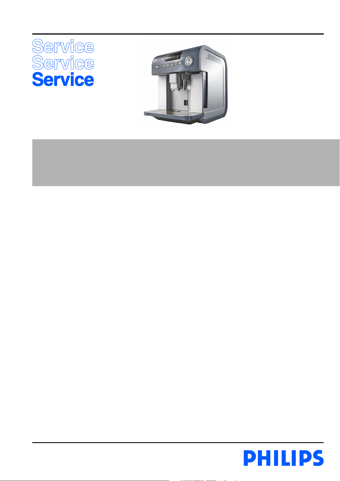
Premium One-touch Espresso maker
HD5730/10
Philips Consumer Lifestyle
Service Manual
PRODUCT INFORMATION
- This product meets the requirements regarding
interference suppression on radio and TV.
- After the product has been repaired, it should function
properly and has to meet the safety requirements as
officially laid down at this moment.
TECHNICAL INFORMATION
- Power rated : 1350 W
- Standby power : 3 W
(switched off)
- Standby power : 80 W
(switched on)
- Voltage : 220 - 240 V / 50 - 60 Hz
- Colour setting : Brushed stainless steel Gun metal
- SAP coding : HD5730/10
OPTIONAL (accessories)
- Hardness test strip Service code : 4222 459 45145
- Durgel bottle DE - GB Service code : 4222 459 45200
- Durgel bottle GB - NL Service code : 4222 459 45201
Published by Philips Domestic Appliances and Personal Care Printed in the Netherlands © Copyright reserved Subject to modification
08/02
Page 2
DISASSEMBLY- AND RE-ASSEMBLY ADVISE
HD5730/10
For your safety, be sure the plug is
!
disconnected from the mains!
- In below steps the dismantling from the appliance has been
written down in a certain sequence.
Please follow the steps in this order.
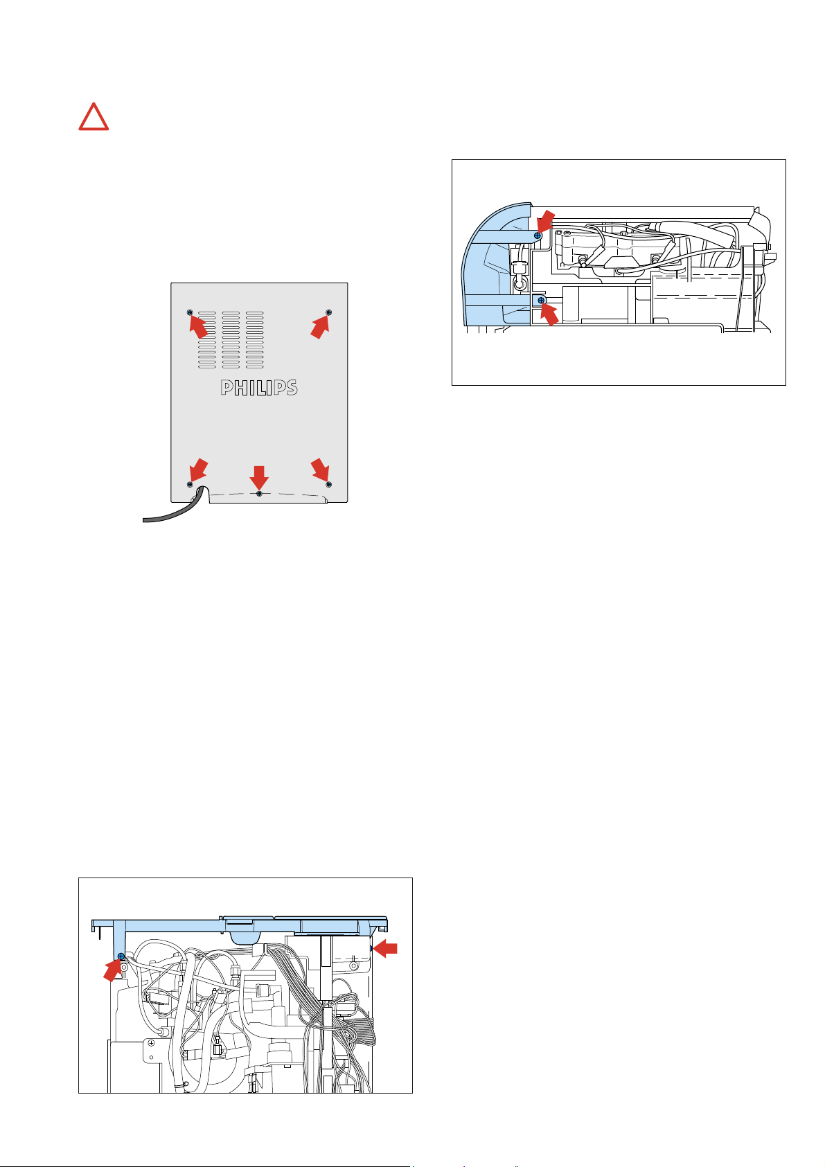
Remove back panel:
- To remove the back panel, first remove the 5 screws,
see picture for positions.
- Slightly lift the back panel upwards.
- The back panel becomes loose.
- Now remove on both sides the upper and lower screws
where the control panel is fixed to the frame!
See picture for positions.
Remove upper screws
on both sides
Remove lower screws
on both sides for
removing the control panel
- Now you are able to remove the control panel.
- The control panel is electrical connected to the machine by
the band cable connection.
- The topcover can be taken of.
Remove the service door:
- The service door can simply be removed by removing the
steel wire located on the left side at the hinge.
- Pull the wire out the hinge and the service door can be
taken away.
- After the back panel has been removed, the way is free to
remove the other panels as well.
Remove left or right panel:
- To remove the left/right panel, slightly move the side panel
± 1 cm backwards and then remove the panel sideward.
Remove topcover + Control panel :
- Open bean lid, remove cap from the grinder adjustment
knob and remove the screw at the inside of the Grinder
Coffee coarseness adjustment knob.
- Mark carefully the position of the knob, before removing it.
(to ensure the right position when re-assembling)
- Remove the left upper screw seen from the back and remove
the screw in the upper corner of the right side, see picture
for the positions.
Screw upper
left backside
Screw upper
corner right panel
Remove bottom cover:
- To reach the micro switch that detects the presence of the
Coffee ground container, the bottom cover has therefore to
be removed.
- At the bottom of the appliance unscrew 7 Torx screws and
remove the cover, micro switch and the lift drive belt can be
reached easily.
- If the above steps are carried out all the parts can be reached
and if needed dismantled/replaced.
2-26
Page 3
REPAIR INSTRUCTIONS
All the display messages that are described in this service manual are in English
!
language. If you want to change the language to English, proceed as follows.
1. Switch appliance on.
2. Press the MENU button.
3. Navigate with the
or
until Display message SET LANGUAGE? appear.
4. Press the OK button to select this routine.
5. Navigate with the
or
Display message ENGLISH appears.
6. Press the OK button 3 seconds to finalize the selection.
HD5730/10
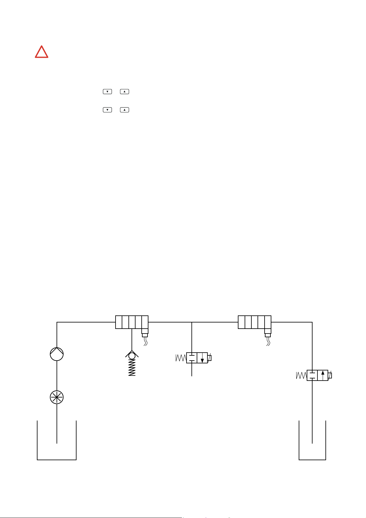
- Water/mechanical circuit
Coffee Heating element
Water Pump
Brewing unit
Water Flowmeter
Water Tank
Temperature
sensor
Steam Heating element
Discharge
Solenoid valve
Temperature
sensor
Frothed
milk exit
2-way
steam valve
Milk Tank
3-26
Page 4
REPAIR INSTRUCTIONS
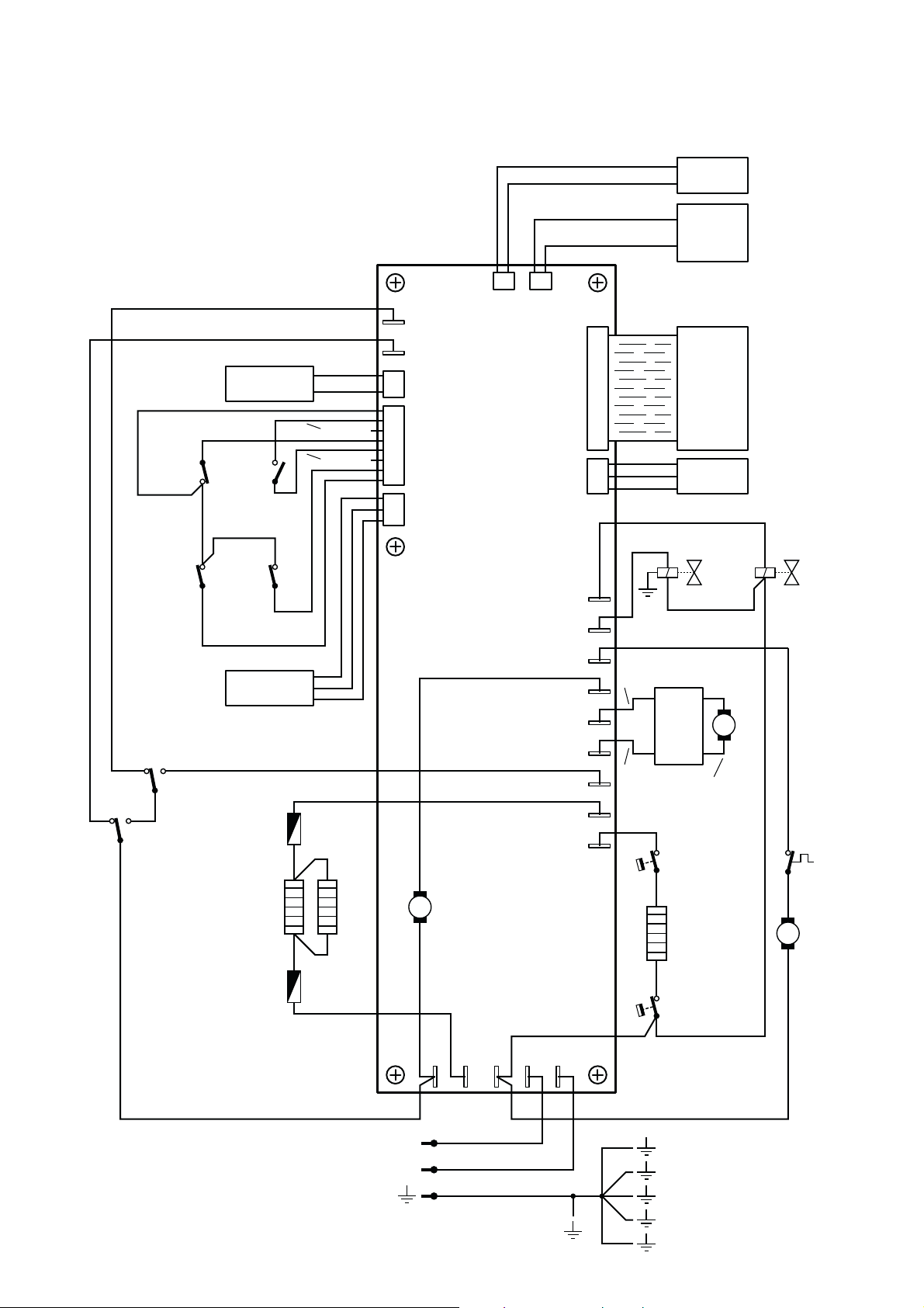
- Electrical circuit
HD5730/10
Reed
sensor
IFD Boiler
Temp.
sensor
Green
Blue
Blue
Brewing
up pos.
Black
M4
Service
door
M3
Coffee
Waste bin
M1
unit
Red
M5
Milk
Jug
White
Brown
Temperature
sensor
Blue
M2
Brewing
unit
down pos.
Brown
M6
Hot
Water
Spout
Red
Water flow
meter
Fuse
Grey
Coffee
Heating
element
Grey
Fuse
Brown
Black
Green
White
White
Grey
J6J7
F14
F15
J5
1
J1
Control
Board
J2
Hall
sensor
2 way
Steam
valve
Brown
Motor
Filter
Board
Brewing unit
Group
motor
Steam
TCO
Steam
Heating
Discharge
electrovalve
+
M
−
Pump
Thermal
protector
Pump
M
J3a
M
Grinder
Motor
Black
White
Grey
J3b
Brown
F12
F11
F10
F13
F9
F8
F7
F6
F5
Red
Brown
Brown
Red
Black
Blue
Red
element
Black
Red
Steam
TCO
Brown
Brown
Mains
Blue
L
N
F0
F1 F2 F3
Brown
Blue
Yellow/Green
F4
Brown
4-26
Page 5

REPAIR INSTRUCTIONS
Working principle of the appliance
To understand the appliance better, hereby a short technical description of the working principle.
When the appliance has been plugged on the mains, the appliance starts with a self diagnose.
First items that will be checked are:
- Temperature sensor(s), state of micro switches.
Second:
- If no malfunction detected the Brewing unit will be moved downwards and after actuating the micro switch
brewing_unit_down_position M2, the brewing unit will be brought to the mid position (in this position it is possible to remove
the Brewing unit for cleaning purposes).
- During this movement the Hall sensor will count the needed cycles to go to the right position.
- After this has been accomplished the appliance will shut it selves off.
If there is a problem detected in above actions the Display will show a “GENERIC ALARM” message.
Note:
If the appliance is still in factory mode, the appliance will not shut it selves off.
First the available languages will be displayed and after the selection of the language the appliance starts the water fi ll routine.
Follow the steps indicated in the displayed after the process the appliance will shut it selves off.
Switching the appliance on:
When the appliance has been switched on the brewing unit will fi rst be brought to the Coffee fi lling position.
Also the 2 heaters (steam and Coffee heater) will be powered and are heating up. (see also message in the display) (heating up….)
When the right temperature (measured by the NTC(s)) has been reached, the Brewing unit will be brought to the brewing (top)
position until the brewing_unit_up_position M1 micro switch is activated.
Then water will be pumped through the brewing unit (see also message in the display) to clean the Coffee system (Brewing unit &
brewing head).
After this routine the Brewing unit will be sent to the down position (by a mechanical mechanism the Coffee grounds) will be
wiped off.
The Brewing unit will be sent to the Coffee fi lling position again and the appliance will show a message on the display that the
machine is READY to USE.
HD5730/10
Brewing cycle Coffee:
When the user selects one of the Coffee buttons (small- , medium- or large cup of Coffee) depending on status of the appliance the
Brewing unit will be sent downwards fi rst and then go to the grinder fi ll position otherwise the fi rst action will be that the beans will
be grinded into Coffee powder. The Coffee powder falls in the Brewing unit.
When the grinder stops grinding, the Brewing unit will be moved up to the brewing position.
The pump starts to pump a small amount of water into the brewing unit (pre-brewing), the Coffee bed will slightly shrink and
therefore the Brewing unit will be sent up to the brewing position again. (few millimetres)
After 1 – 2 seconds the pump continues to pump the water through the brewing unit and Coffee will leave the Brewing unit via the
Coffee spout into the cup.
When the right quantity of water has been reached (measured by the fl ow counter), the pump stops.
The Brewing unit will be sent to the down position.
In the down position the Coffee residue will be wiped off. The coffee will fall in the removable waste bin container.
After this the Brewing unit will be sent to the Coffee fi ll position again.
The Coffee brewing cycle has been performed.
5-26
Page 6
REPAIR INSTRUCTIONS
HD5730/10
Service testroutines
This appliance has been equipped with special “service” routines to be able to check several functions of the appliance.
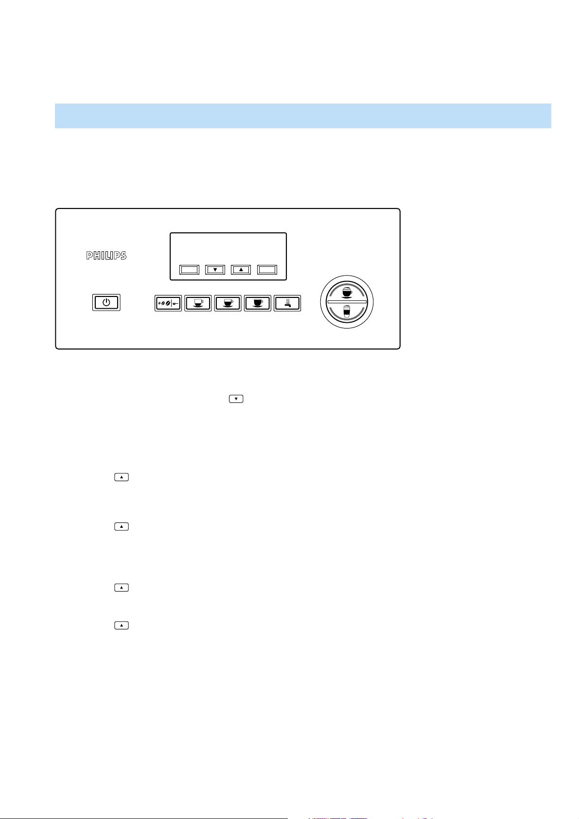
COUNTING PROCEDURE
With the counting procedure can be checked how (intense) the machine has been used by the consumer.
Items that are monitored:
Number of Coffee made, liters of water used, number of descaling procedures performed, number of cleaning/washing cycles
performed and number of cappuccinos made.
MENU OK
Entering the counting menu
1. Disconnect the appliance from mains.
2. Press simultaneously “MENU” and
button.
3. Connect the appliance to mains.
4. If above steps succeeded the display will show the following message
“TOT. COFFEE XXX”
”TOT. WATER XXX”
* where XXX is number of cups or Liters
5. Press
button to step to the next display message
”DESCALING XXX”
”WASHING XXX”
* where XXX is number of cycles performed
6. Press
button to step to the next display message
”SW RELEASE POW 15”
”SW RELEASE DIS 15”
* where POW 15 stands for power PCB software version release 1.5
* where DIS 15 stands for display PCB software version release 1.5
7. Press
button to step to the next display message
”TOT. CAPPUCC. XXX”
* where XXX is number cups cappuccino made
8. Press
button, step 4 will be repeated.
P
P
A
U
C
C
C
O
I
T
N
U
O
A
A
U
T
O
O
T
A
I
H
L
A
C
T
C
T
A
E
M
To leave the service/test mode unplug the appliance from the mains.
6-26
Page 7
REPAIR INSTRUCTIONS
HD5730/10
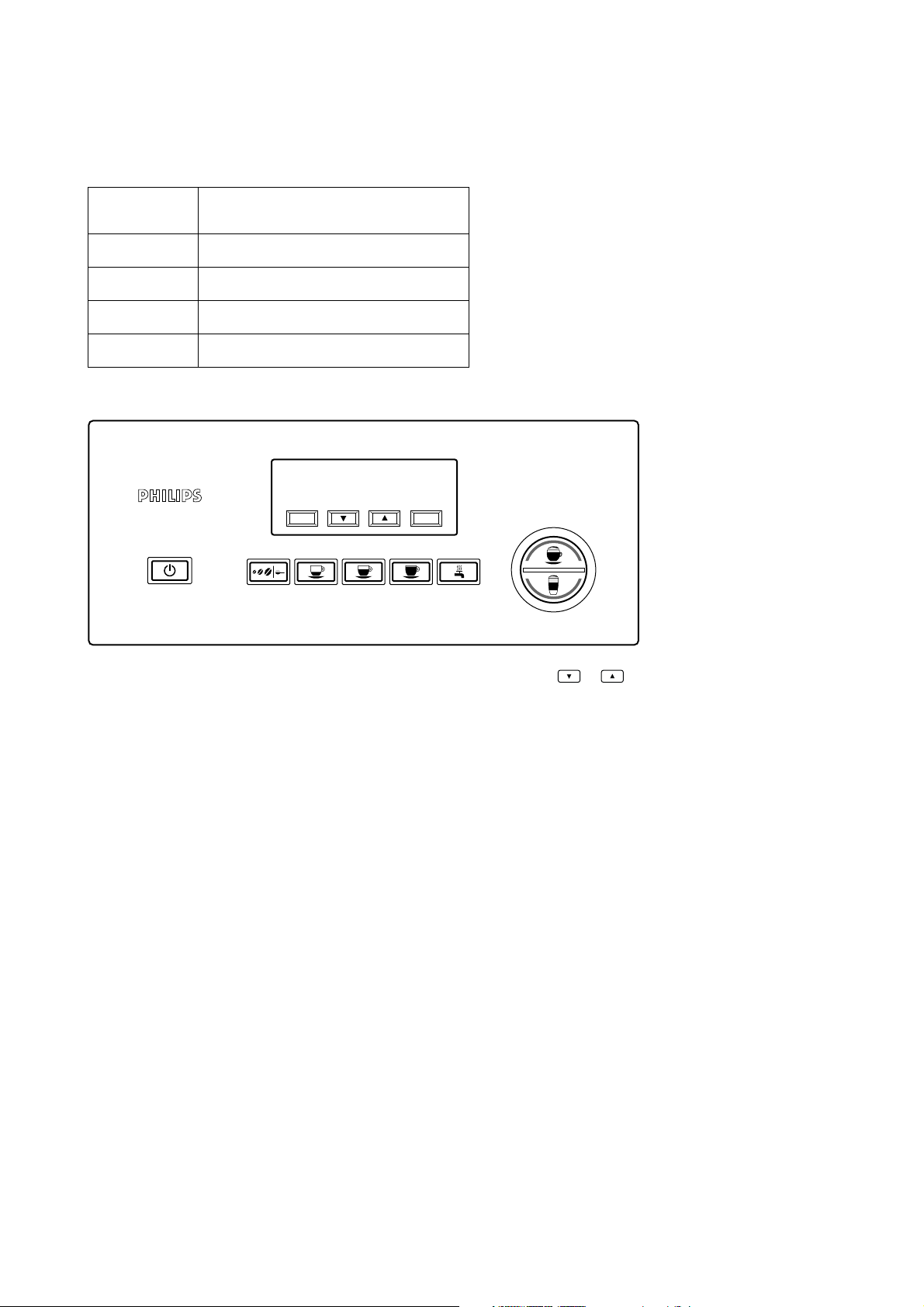
For repair solutions it is good to know if the descale procedures are performed in line with the coffee/cappuccinos brewed.
In below table you can fi nd the values depending on the water hardness setting when the appliance will inform the consumer that
the appliance has to be descaled!
Water hardness
setting
Litres water after which the decalcifying
routine must be performed (L)
1 250
2 150
3 80
4 45
Check the installed Water hardness setting.
MENU OK
P
P
A
U
C
C
C
O
I
T
N
U
O
A
A
U
T
O
O
T
A
I
H
L
A
C
T
C
T
A
E
M
Press the “MENU” button and walk through the menu items by means of the
or
buttons until
WATERHARDNESS X is displayed.
The number X represents the Water hardness setting.
Calculate the number of liters displayed in combination with the installed hardness setting in the table.
Example 1: Example 2: Example 3:
• Display shows 120 • Display shows 700 L • Display shows 1000 L
• Hardness setting 4 • Hardness setting 3 • Hardness setting 1
• Performed cycles decalcifying 3. • Performed cycles decalcifying 3. • Performed cycles decalcifying 3.
Calculation: Calculation: Calculation:
120/45 = 2.66 round down to => 2. 700/80 = 8.75 round down to => 8 1000/250 = 4
2 – 3 = –1 < 3 8 – 3 = 5 > 3 4 – 3 = 1 < 3
Descaled routines performed ok! Descaled routines performed Not OK! Descaled routines performed ok!
If the number of decalcifying routines performed deviates more than 3 times of the formula outcome the machine has not been
properly decalcifi ed.
Conclusion:
The outcome of the formulas must be more or less equal to the number of decalcifying routines carried out by the consumer.
Example1 and Example3 are in line with the recommanded number of descal routines performed as requested by the appliance.
Example2 there it is clear that the appliance has not been descaled according the instructions given by the appliance.
The outcome of the formula deviates more than 3 times of the requested number of descaling of the appliance.
7-26
Page 8
REPAIR INSTRUCTIONS
HD5730/10
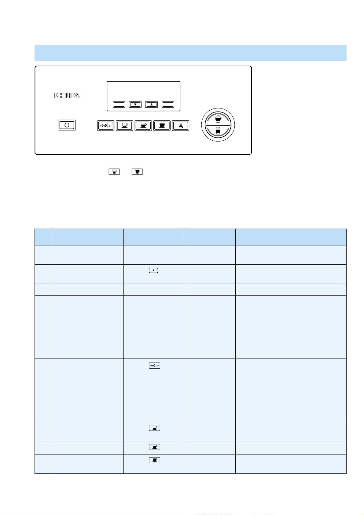
PUTTING THE APPLIANCE INTO SERVICE/TEST MODE
MENU OK
P
P
A
U
C
C
C
O
I
T
N
U
O
A
A
U
T
O
O
T
A
I
H
L
A
C
T
C
T
A
E
M
1. Disconnect the appliance from mains.
2. Press simultaneously and Coffee buttons.
3. Connect the appliance to mains.
4. If above steps succeeded the display will show the following message “LOAD TEST MODE”
Using the functions in the Service/test mode.
When the Service/test mode is entered, the following functions can be carried out / checked.
Function selection Action to perform Display message Result of the action
1. Operate Brewing Heater Push the MENU
button
2. Operate Pump
Push the
button
HEATER ON The Brewing heater will be powered, check
power consumption (± 1240 W). *
PUMP ON If water container is fi lled and placed the
pump will be powered (± 40 W).
3. Operate the grinder Push the OK button GRINDER ON Grinder will grind “Beans”.
4. Operate Brewing unit
upwards (motor lift)
Push the On/OFF
button
MOTOR UP
If this function will be performed always
be sure the Brewing unit has been installed,
service door is closed & Coffee ground
&
container is in place.
If the brewing unit_up_position M1
has been activated by the Brewing unit
5. Operate Brewing unit
down (motor lift)
Push the
button
LIMIT SWITCH
UP
MOTOR DOWN
the Display will show message LIMIT
SWITCH UP.
If this function will be performed always
be sure the Brewing unit has been installed,
service door is closed & Coffee ground
&
container is in place.
If the brewing unit_down_position M2
has been activated by the Brewing unit
6. Operate discharge valve
Push the button
LIMIT SWITCH
DOWN
EV1 ON The 3way discharge valve will be powered.
the Display will show message LIMIT
SWITCH DOWN.
(EV1)
7. Operate Steam valve (EV2)
8. Operate steam Heater
Push the button
Push the button
EV2 ON The 2way steam valve will be powered.
VAPORIZER ON The steam heater will be powered, check
power consumption (± 900 W). *
8-26
Page 9
REPAIR INSTRUCTIONS
HD5730/10
* When powering the heaters in the system via the service test mode be warned that you not power the heaters too long,
!
the software is not protecting the heaters in this state!!
To leave the service/test mode unplug the appliance from the mains.
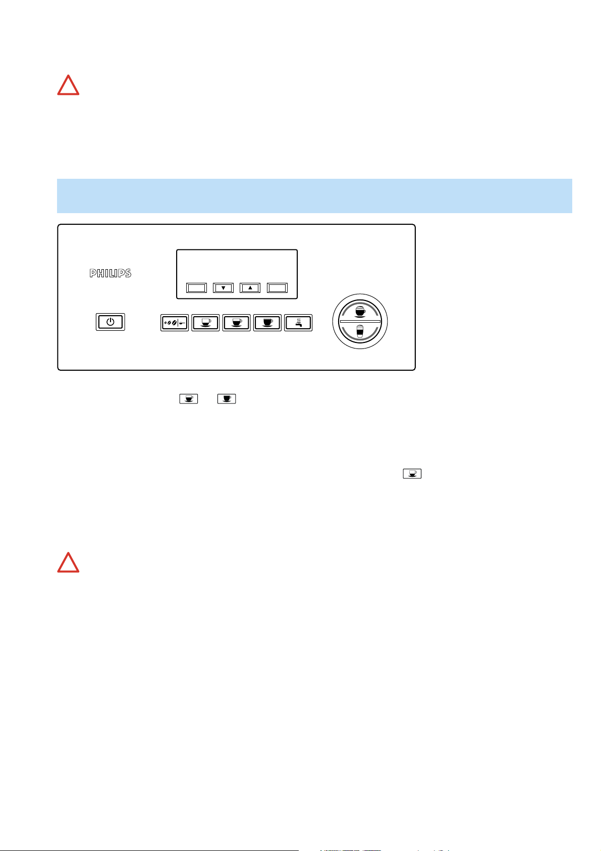
PUTTING THE APPLIANCE INTO DISPLAY TEST MODE *
(Factory Virgin mode)
MENU OK
P
P
A
U
C
C
C
O
I
T
N
U
O
A
A
U
T
O
O
T
A
I
H
L
A
C
T
C
T
A
E
M
1. Disconnect the appliance from mains.
2. Press simultaneously and Coffee buttons.
3. Connect the appliance to mains.
4. If above steps succeeded the display will show the following message “DISPLAY TEST MODE”
In the display test mode it is possible to check if the menu buttons are recognized by the software.
For instance pressing the MENU button the display will show Button 1, if you press the button, display will show
Button 2 pressed etc.!
In this manner it is possible to check if the buttons are recognized by the software.
To leave the service/test mode unplug the appliance from the mains or wait 45 seconds without pressing any button.
When powered again the appliance must be fully installed again!
!
9-26
Page 10
REPAIR INSTRUCTIONS
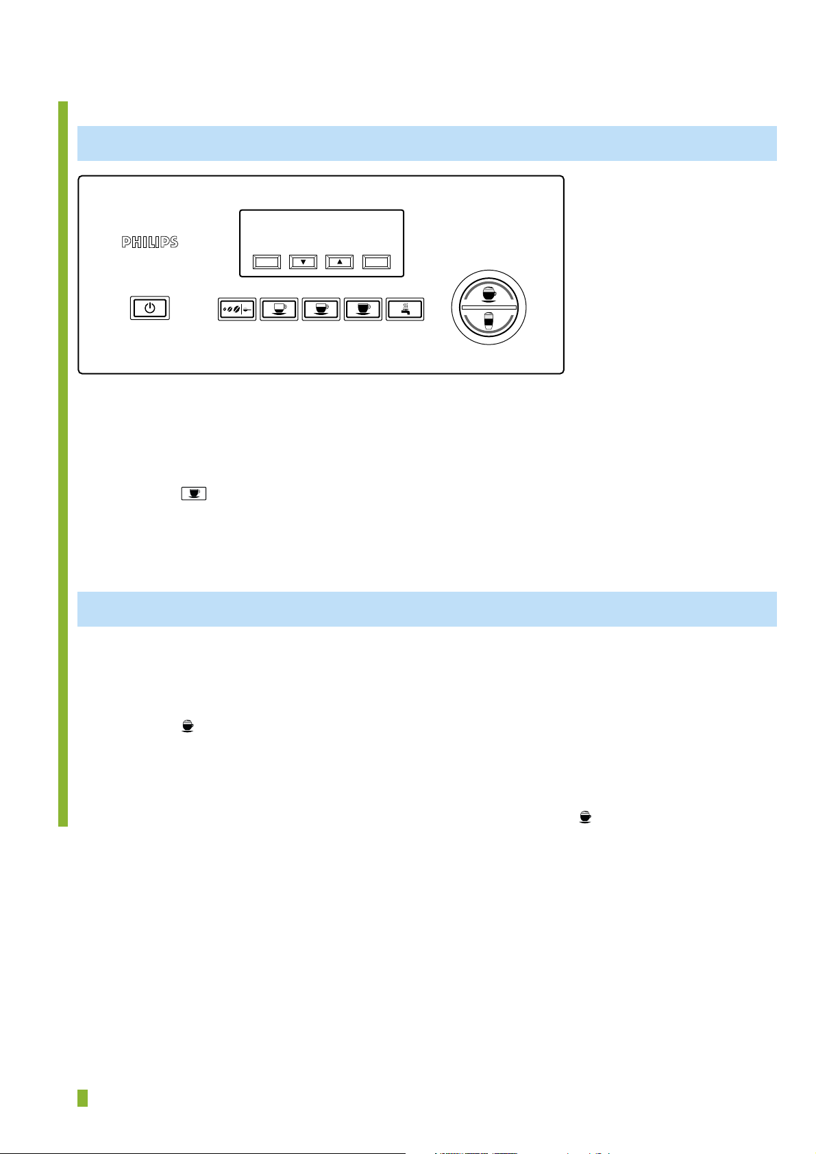
Temperature measurement.
COFFEE TEMPERATURE MEASUREMENT PROCEDURE
HD5730/10
MENU OK
O
T
U
A
A
U
T
O
L
A
1. Switch appliance on.
2. Make sure appliance factory default settings are stored.
3. place a plastic cup under the coffee spout.
4. Set grinder setting on position 7.
5. Fill water tank and bean compartment.
6. Press the
button.
7. During the cup is filled with Coffee measure the temperature.
8. Repeat step 6 – 7 once and note the highest measured temperature.
9. For validation see table page 11.
MILK FROTH TEMPERATURE MEASUREMENT PROCEDURE
1. Switch appliance on.
2. Make sure appliance factory default settings are stored.
3. place a plastic cup under the milk spout.
4. Fill the milk jug tank with cold milk to the max level.
5. Press the
button twice.
6. During the cup is filled with milk measure the temperature.
7. Repeat step 5 – 6 once and note the highest measured temperature.
8. For validation see table page 11.
P
P
A
U
C
C
C
I
N
O
O
T
A
I
H
C
T
C
T
A
E
M
For Cappuccino temperature check repeat above steps (only press once)
= changed
10-26
Page 11
REPAIR INSTRUCTIONS
HD5730/10
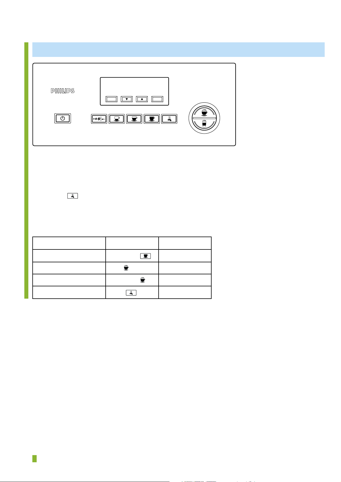
WATER TEMPERATURE MEASUREMENT PROCEDURE
MENU OK
C
O
T
U
A
A
U
T
O
L
A
T
1. Switch appliance on.
2. Make sure appliance factory default settings are stored.
3. Install water spout.
4. Place a plastic cup under the water spout.
5. Fill the water tank with water.
6. Press the button.
7. During the cup is filled with water measure the temperature.
8. Repeat step 6 – 7 once and note the highest measured temperature.
9. For validation see table below.
Beverage Function Temperature spec.
Coffee temperature (°C) Long Coffee
≥ 75°C
P
P
A
U
C
C
I
N
O
O
T
A
I
H
C
C
T
A
E
M
Milk froth temperature (°C) Milk (2 x) ≥ 51°C
Cappuccino (°C) Coffee/Milk ≥ 61°C
Hot water Water ≥ 80°C
= changed
11-26
Page 12
REPAIR INSTRUCTIONS
Check Milk froth foam quality.
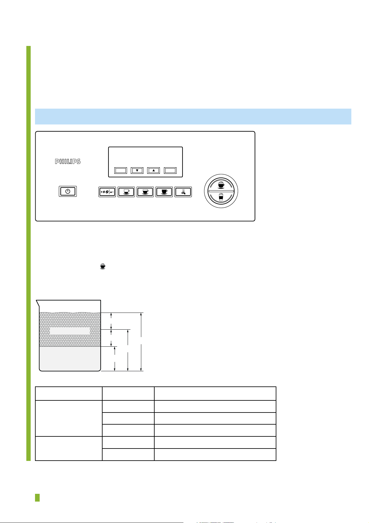
Offi cial test according IEC-60661.
Before performing the test the following is needed:
Partially Skimmed cold milk. (fat 1.5 %)
Cylindrical glass 75 - 80 mm with inner diameter 80 ± 2 mm.
MILK FROTH QUALITY MEASUREMENT PROCEDURE
HD5730/10
MENU OK
P
P
A
U
C
C
C
O
I
T
N
U
O
A
A
U
T
O
O
T
A
I
H
L
A
C
T
C
T
A
E
M
1. Switch appliance on.
2. Make sure appliance factory default settings are stored.
3. place the cylindrical glass under the milk spout.
4. Fill the milk jug tank with cold milk to the max level.
5. Press the button
twice.
6. When the cycle has been completed let the milk foam stabilize for one minute and please judge the foam quality
according below table and for dimensions see table + drawing.
=
Milk froth/foam
Milk
=
L
1
L
3
L
2
Criteria Value
Porosity/quality foam Not Acceptable With big bubbles comparable to soap bubbles
Acceptable Comparable to beer foam
Good Similar to whisked egg white
Foam volume Acceptable L3 bigger or equal to 2 * L
Not Acceptable L3 less than 2 * L
1
1
= changed
12-26
Page 13
REPAIR INSTRUCTIONS
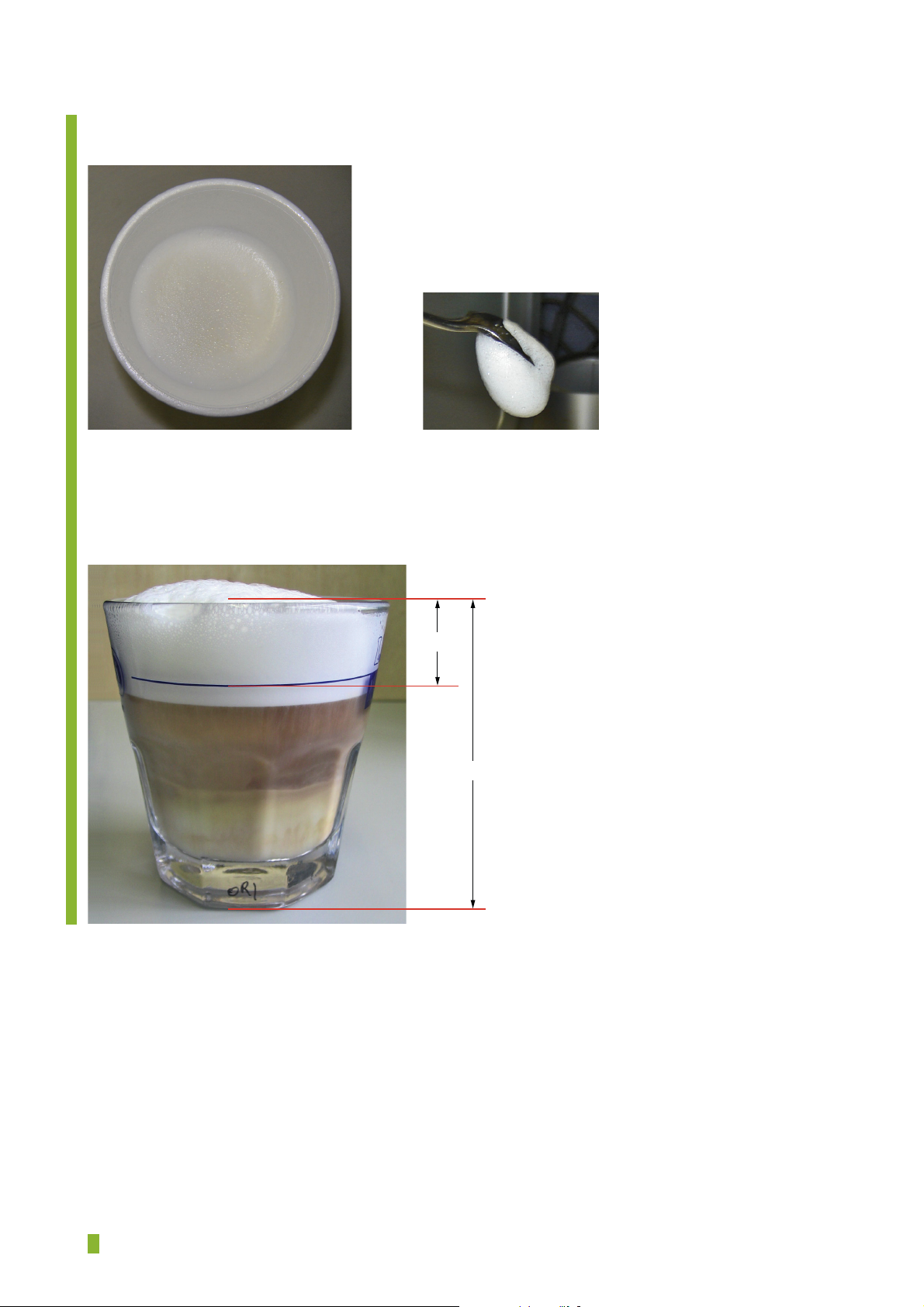
To practical judge the foam height/quality see picture for references.
Milk foam quality current Galileo (reference)
Characteristics:
- Solid foam layer
- Small bubbles in foam layer
- Keeps sticking on spoon
HD5730/10
± 25mm
90mm
= changed
13-26
Page 14
TROUBLE SHOOTING
Technical related problems.
Warning:
!
Live Voltage is applied to the micro switches used in the appliance!!!!!
Always disconnect plug from the mains when repairing!
When the appliance generates a GENERIC ALARM message, the only way to reset this is
by unplugging the power plug from the mains.
FAILURES AT PLUGGING IN APPLIANCE
HD5730/10
Problem description /
“Error” message displayed
1. Appliances doesn’t work
at all.
2. MESSAGE
GENERIC ALARM !
3. MESSAGE
PLEASE WAIT......
Actions to perform Hints/tips/solution
Check if main voltage is applied on the main
PCB (vertical PCB on the right side) by
measuring the voltage (220 - 230 V) on the
connector F3 and F4.
(see electrical drawing scheme)
• Check micro switch (M1) top position
brewing unit and it’s circuit.
• Check NTC sensor (J5) heater and it’s
circuit.
• Check NTC sensor (J6) steam heater and
it’s circuit.
• Check Hall sensor (J3B) motor lift and it’s
circuit.
• If a normal motor sound of the brewing
unit lift is noticed, but the brewing unit
doesn’t move, check the driving belt.
• If a motor sound is noticed and afterwards
you hear a hard noise sounding like a
blocked motor and the brewing unit stays
at bottom position, check the micro switch
(M2) bottom position brewing unit and it’s
circuit.
• If no motor sound is noticed, check the
wire connection of the motor and see if
voltage has been applied on the motor side.
• If no motor sound is noticed and also no
voltage has been measured on pins F7 &
F8 PCB probably the 2 relays on the main
PCB became defect.
If no voltage is present:
check power cord and connections!
If voltage is present, check all electrical
connections on the PCB, otherwise exchange
PCB.
• Micro switch is NC (normally closed)
(exchange switch)
• Value NTC resistor at 23 °C ± 110 kΩ
➟ ± 95 °C = 5.3 kΩ
• Value NTC resistor at 23 °C ± 110 kΩ
➟ ± 135 °C = 2.5 kΩ
• Value measured on PCBA J5/J6
(without NTC) ± 10 kΩ
• If the GENERIC ALARM message
appears after the brewing unit went down,
most probably the Hall sensor/connections
is the problem. (counting of pulses starts
after actuating the brewing unit_down_
position M2, so going up direction!)
• Belt broken, replace belt.
• Replace micro switch (M2).
• If voltage on the motor circuit board has
been applied, motor is probably defect.
Exchange total brewing unit lift assy.
• Exchange main PCB
4. MESSAGE
CLOSE DOOR !
5. MESSAGE
INSERT WASTE BIN !
= changed
• Close the service door.
• Check the function and circuit of micro
switch (M4).
• Check if the micro switch mechanical will
be activated if the door is closed.
• Place waste bin.
• Check the function and circuit of micro
switch (M3).
• Check if the micro switch mechanical will
be activated if the waste bin is placed.
• Exchange micro switch. (M4).
• Exchange micro switch. (M3).
14-26
Page 15
TROUBLE SHOOTING
HD5730/10
FAILURES WHEN SWITCHING ON THE APPLIANCE
Problem description /
“Error” message displayed
1. MESSAGE
No WATER !
-Fill watertank-
2. MESSAGE
HEATING UP
PLEASE WAIT...
After ± 6 minutes
GENERIC ALARM !
Actions to perform Hints/tips/solution
• Fill tank with water.
• Check function of the Reed sensor
(no magnet, open contact = >>> Ω,
magnet closed contact = 0 Ω)
• Check if Coffee heater is heating up.
• Check if the steam heater is heating up.
• Check if fi lled tank is inserted correctly.
• Check presence of Magnet in tank or see if
it is jammed.
• For testing purposes short circuit jumper
(J7) display message will disappear.
• Exchange Reed sensor.
• Check voltage is present on connectors
(F1) & (F6) (if not exchange PCB)
• Check Fuse/TCO became defect (2x)
(exchange when defect)
• Check resistant of heating element.
(45 - 55 Ω) (exchange when defect)
• If coffee heating element is heating up
check function/circuit of NTC coffee
heater. (J5) PCB.
• Check voltage present on connectors (F2)
& (F5) (if not exchange PCB)
• Check Fuse/TCO became defect (2x)
(exchange when defect)
• Check resistant of heating element.
(45 - 55 Ω) (exchange when defect)
• If steam heating element is heating up
check function/circuit of NTC coffee
heater. (J6) PCB.
3. MESSAGE
INSERT BREWING
UNIT !
4. MESSAGE
Flushing…
After 20 – 30 seconds
‘GROUND TOO
FINE! –Adjust mill’
and ‘INSERT WATER
SPOUT !’
• Place brewing unit.
• Check the function and circuit of micro
switch (M1).
• Check if the micro switch mechanical will
be activated if the brewing unit is properly
placed and the brewing unit is in top
position.
• When water is pumped through the
system, the fl ow meter measures the
pumped volume. When the system detects
a mismatch in expected and measured
volume the failure will be displayed.
• Check if the pump is pumping.
• Check the fl ow meter and it’s circuit is
functioning.
• Exchange micro switch. (M1).
• Check if water is present in the water
container and the water container has
been correctly placed. See if water is
visible in the area container - pump.
• Check if the pre fi lter not became clogged
by particles.
• Check if voltage is during pumping
present on connectors (F2) & (F10).
(if not exchange PCB)
• Check if voltage is during pumping
present on the pump.
(if not check the TCO on the pump,
exchange when defect)
• Exchange pump.
• Exchange Flow meter.
15-26
Page 16
TROUBLE SHOOTING
HD5730/10
FAILURES DURING OPERATING THE APPLIANCE
Problem description /
“Error” message displayed
1. MESSAGE
NO COFFEE BEANS!
- Fill container-
2. MESSAGE
LESS GROUND
COFFEE !
Actions to perform Hints/tips/solution
• Fill container with beans.
• No motor sound during grinding process is
noticed.
• You hear a humming noise or rattle sound,
probably the grinder is blocked by a stone
or other material.
• The coarseness of the Coffee grinder is set
to fi ne, so almost no coffee will be grinded.
• The micro switch (M1) brewing unit top
position has been activated to soon when
the brewing unit move upwards or brewing
unit position counter (J3B) (Hall sensor)
is inaccurate (time and position is how
the appliance detects if ground Coffee is
present)
• User selected Coffee ground
• To less ground Coffee has been applied.
• The pre-ground Coffee funnel has been
blocked!
• The micro switch (M1) brewing unit top
position has been activated to soon when
the brewing unit move upwards or brewing
unit position counter (J3B) (Hall sensor)
is inaccurate (time and position is how
the appliance detects if ground Coffee is
present)
• Check if beans are visible in the grinder.
• Check if voltage is present during grinding
on the (F0) & (F9) connectors.
(if not exchange PCB)
• Check wires/connection grinding motor
and replace grinding unit in case the
motor is defect.
• Remove the obstacles out of the grinder
wheels.
• Adjust the Grinder coarseness.
(turn clockwise)
• Check if micro switch is properly
functioning and/or is activated properly by
the mechanical action of the brewing unit.
• Check Hall sensor is correct counting/
detecting position.
• Add pre-ground Coffee.
• Supply one Coffee spoon of ground coffee.
• Open/clean the pre-ground Coffee funnel.
• Check if micro switch is properly
functioning and/or is activated properly by
the mechanical action of the brewing unit.
• Check Hall sensor is correct counting/
detecting position.
3. MESSAGE
EMPTY WASTE BIN !
• Empty waste bin. Check the function and
circuit of micro switch (M3).
• Check if the micro switch mechanical will
be activated/de-activated if the waste bin
will be removed/inserted.
• When emptying waste bin the software
monitors if the waste bin micro switch
(M3) has been inactivated for at least
15 seconds. (time needed to dispose the
coffee) (appliance must be plugged on the
mains to monitor this action.
• Exchange micro switch. (M3).
16-26
Page 17
TROUBLE SHOOTING
HD5730/10
FAILURES DURING OPERATING THE APPLIANCE
Problem description /
“Error” message displayed
4. MESSAGE
Please wait…..
Flushing…. Or
Coffee….
After 20 – 30 seconds
‘GROUND TOO
FINE! –Adjust mill’
and ‘INSERT WATER
SPOUT !’
Actions to perform Hints/tips/solution
• When water is pumped through the
system, the fl ow meter measures the
pumped volume. When the system detects
a mismatch in expected and measured
volume the failure will be displayed.
• Check if the grinder is not grinding the
Coffee too fi nely, that no Coffee is coming
out the spouts.
• Check if the pump is pumping.
• Check the fl ow meter and it’s circuit is
functioning.
• Check fi nes of the grinder; adjust grinder
see instruction Grinder adjustments.
• Check if water is present in the water
container and the water container has
been correctly placed. See if water is visible
in the area container - pump.
• Check if the pre fi lter not became clogged
by particles.
• Check if voltage is during pumping
present on connectors (F2) & (F10)
(if not exchange PCB)
• Check if voltage is during pumping
present on the pump.
(if not check the TCO on the pump,
exchange when defect)
• Exchange pump.
• Exchange Flow meter.
5. MESSAGE
‘NO MILK JUG !’
-Please insert milk jug -
6. MESSAGE
‘INSERT WATER
SPOUT !’
• Place the Milk jug fi rm and properly to the
machine.
• Check the function and circuit of micro
switch (M5).
• Check if the micro switch mechanical will
be activated/de-activated if the milk jug will
be removed/placed.
• Place the water spout properly to the
machine.
• Check the function and circuit of micro
switch (M6).
• Check if the micro switch mechanical will
be activated/de-activated if the water spout
will be removed/placed.
• Check if micro switch is properly
functioning and/or is activated properly by
the mechanical action of placing the milk
jug.
• Replace micro switch (M5).
• Check if micro switch is properly
functioning and/or is activated properly by
the mechanical action of placing the water
spout.
• Replace micro switch (M6).
17-26
Page 18
TROUBLE SHOOTING
OTHER FAILURES
Problem description Actions to perform Hints/tips/solution
HD5730/10
1. During heating up water is
dripping from the Brewing unit.
OR
I selected hot water but the
water is leaking via the brewing
unit inside of the appliance.
2. Coffee is not coming out of the
spout.
3. The coffee is not hot. • Mostly the problem is caused by the fact
4. Cappuccino/Latte Macchiato or
Milk froth temperature too low.
• The valve construction in the (yellow
tube) thermo heater became defect.
• Check if the holes of the spout are not
clogged.
• Check if the mobile drawer inside the
service door is blocked and cannot swing.
• The coffee is not running out of the
brewing unit spout but is leaking through
the brewing unit.
people use big not pre-heated mugs for
small amounts of Coffee.
• Increase the coffee temperature in the
menu.
• Measure the Coffee temperature see
instruction “Temperature measurement”.
• Mostly the problem is caused by the fact
people use big not pre-hearted mugs.
• Increase the coffee temperature in the
menu.
• Measure the Coffee temperature see
instruction “Temperature measurement”.
• Check the O-rings in the brewing
unit (pos 45)
• Check the spring in the brewing unit
(pos 48)
• Check the shaft in the brewing unit.
(pos 46)
• Clean or open the holes with a
needle.
• Check the function of the drawer and
clean it thoroughly so it can swing
again.
• Check the O-rings in the brewing
unit otherwise replace brewing unit.
• If the temperature is really too low,
descale appliance.
• Check function of NTC
• Replace coffee heater.
• Pre-heat the mug
• Make sure the Milk Jug lid and
Milk lid connection at the appliance
(pos 91) is clean.
5. The coffee is not creamy
enough.
6. The Milk foam layer has bad
quality.
7. The coffee is too strong. • The coffee is ground too fi nely.
8. The coffee is too weak. • The coffee is ground too coarsely.
• The coffee is ground too coarsely.
Turn the grinding coarseness knob one
setting anticlockwise while the mill is
grinding coffee beans.
• To check the Foam quality see instruction
“Check Milk froth foam quality”.
Turn the grinding coarseness knob
one setting clockwise while the mill is
grinding coffee beans.
• Change the coffee strength with the
coffee strength button
Turn the grinding coarseness knob one
setting anticlockwise while the mill is
grinding the coffee beans.
• Change the coffee strength with the
coffee strength button.
• Check fi nes of the grinder; adjust
grinder see instruction Grinder
adjustments.
• Use cold ± 7 °C, skimmed or semi-
skimmed milk.
• Press the clean button ± 5 sec on the
milk jug lid to pre-heat the system.
• Make sure the Milk Jug lid and
Milk lid connection at the appliance
(pos 91) is clean.
• Check fi nes of the grinder; adjust
grinder see instruction Grinder
adjustments.
• Check fi nes of the grinder; adjust
grinder see instruction Grinder
adjustments.
= changed
18-26
Page 19
TROUBLE SHOOTING
OTHER FAILURES
Problem description Actions to perform Hints/tips/solution
HD5730/10
9. The coffee tastes bad.
10. The water system has been
damaged due to the fact the
appliance has been stored /
transported in freeze cold.
• Clean the appliance with the ‘cleaning’
function in the menu.
• Descale the appliance with the ‘descaling’
function in the menu.
If the water system has been frozen, most
probably the appliance is not able to make
Coffee any more.
The water cannot reach the Coffee powder
any more or water is leaking out of the
brewing unit.
The valve used in the brewing unit (yellow
tube) is mostly the part that has to be
replaced.
• Taste is really user depended, only
cleaning, descaling and checking
of the grinder adjustment are
possibilities to check. (assumption is
that the appliance functions normal!)
• Check the O-rings in the brewing
unit (pos 45)
• Check the spring in the brewing unit
(pos 48)
• Check the shaft in the brewing unit.
(pos 46)
• Check the valve (pos 47)
19-26
Page 20
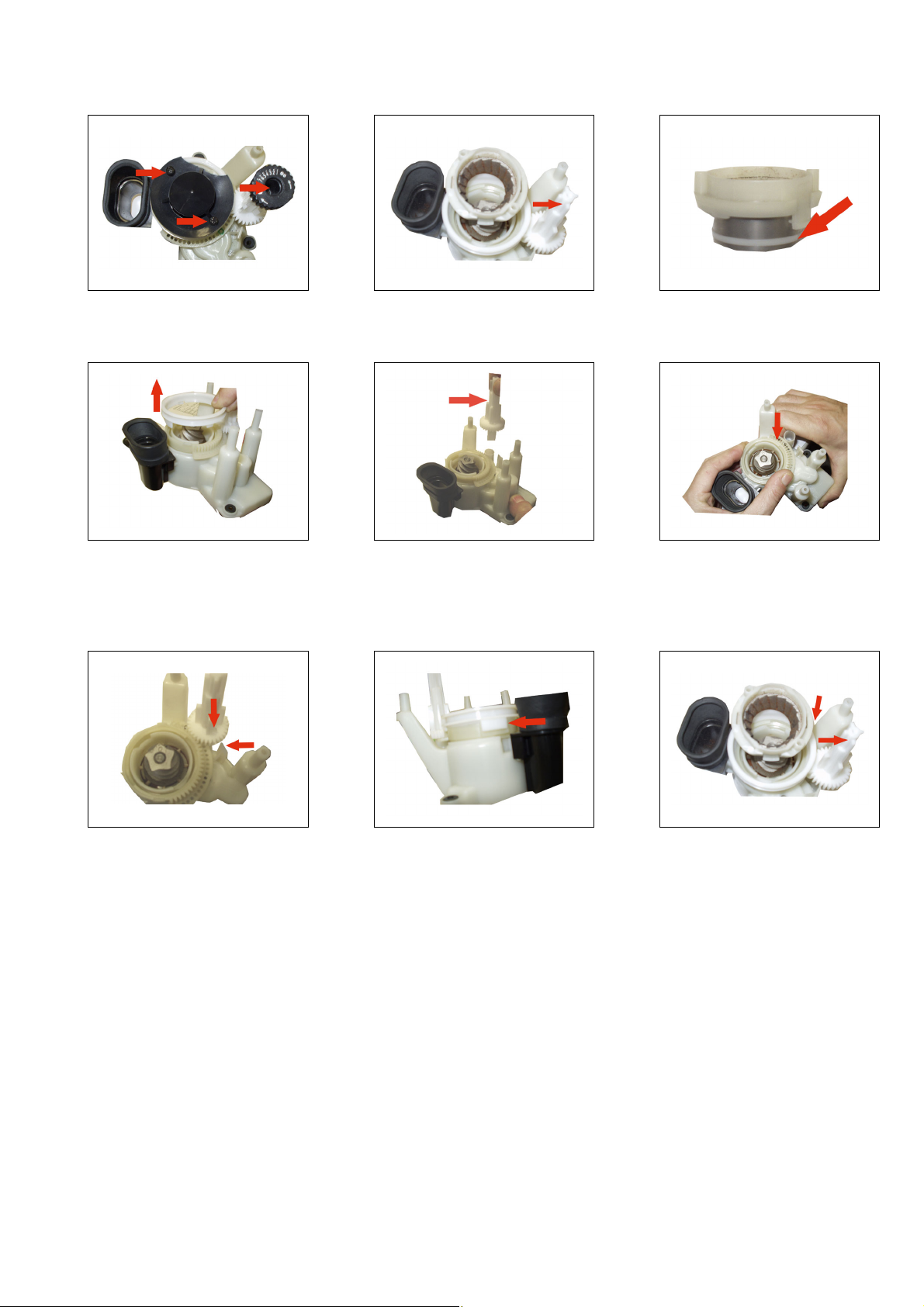
GRINDER ADJUSTMENTS
HD5730/10
12
Remove the coffee beans container,
the black fi nger saver and the knob.
Turn the white shaft clockwise till it
stops. Remove the upper part of the
grinder by pulling it upwards.
45
Remove the white plastic ring by
pulling it.
Turn the white shaft counterclockwise till it stops.
Pull to remove it.
3
Verify the position of the white
gasket (has to be as on the picture)
6
Now you can change the setting:
Turn the gear clockwise* to reduce
the coarseness (fi ner coffee).
Turn the gear counterclockwise* to
increase the courserness (thicker).
789
Insert the white shaft, making sure
its larger notch is aligned with the
one on the grinder.
(*) before to change the setting, check and mark the initial position taking as reference the position of the metal ball you see
through the holes on the white ring.
Change the setting carefully by turning the white ring of one or max two steps (one or two holes) either way as required.
Insert the white ring making sure
its notch as well is inserted on the
correct position.
Turn the shaft CLOCKWISE till it
stops to insert the upper gear.
Then turn the shaft all the way
COUNTER CLOCKWISE.
20-26
Page 21

DESCALING THE APPLIANCE
Proceed as follows:
• Place the WATER SPOUT
• Press the MENU button.
• Press the
• Press OK.
• The message ‘ADD DESCALER! - Push OK when ready’ appears on the display.
Use the bottle of durgol® descaler.
Fill the water tank with the entire bottle of durgol® descaler (125 ml) and 1 litre of water.
Note:
Use the descaler supplied with the appliance or a liquid descaler based on citric acid. Never use a descaler with acetic acid, as this
will damage the appliance.
Note:
Be careful not to spill descaler on the metal surfaces of the machine and on surfaces sensitive to acid such as marble, limestone and
glaze. If you spill descaler on these surfaces, immediately wipe it off with a cloth to prevent stains.
Follow further instruction as indicated on the display.
button until the message ‘START DESCALING?’ appears on the display.
HD5730/10
Note:
If the descaling program is interrupted before completion, the appliance continues to display the message ‘PLEASE DESCALE!’ and
you have to start the program from the beginning again.
21-26
Page 22
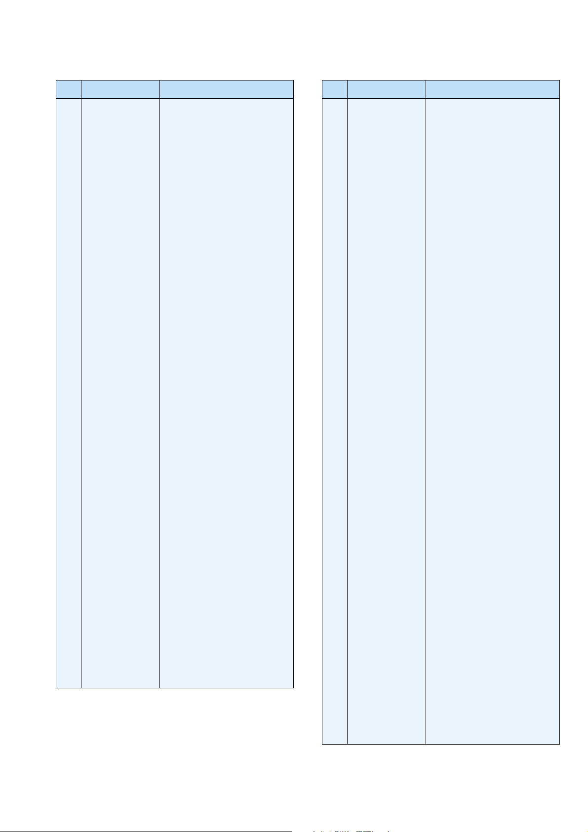
PARTS LIST
HD5730/10
Pos Service code Description
1
4222 459 45085
2
4222 459 45135
3
4222 459 45168
4
4222 459 45134
5
4222 459 45119
6
4222 459 45113
7
4222 459 45193
8
4222 459 45131
9
4222 459 45166
10
4222 459 45165
11
4222 459 45133
12
4222 459 45159
13
4222 459 45142
14
4222 459 45089
15
4222 459 45167
16
4222 459 45162
17
4222 459 45184
18
4222 459 45170
19
4222 459 45098
20
4222 459 45197
21
4222 459 45141
22
4222 459 45143
23
4222 459 45137
24
4222 459 45172
25
4222 459 45138
26
4222 459 45164
27
4222 459 45139
28
4222 459 45186
29
4222 459 45196
30
4222 459 45128
31
4222 459 45161
32
4222 459 45177
33
4222 459 45163
34
4222 459 45171
35
4222 459 45117
36
4222 459 45191
37
4222 459 45088
38
4222 459 45108
39
4222 459 45175
40
4222 459 45090
41
4222 459 45189
42
4222 459 45110
43
4222 459 45109
44
4222 459 45092
45
4222 459 45116
Strength selection cap
Strength selection knob
Left side panel
Beans container
Grinderwheel cap
Ground coffee funnel (gasket)
Complete Grinder
Bottom plate
Bean container lid
Ground Coffee container lid
Measuring spoon
Top cover assy
Rear panel
Microswitch
Right side panel
Control panel
Buttons + frame assy
Button assy
Control board PCB
Door assy
Spout cover
Front panel
Waste Bin
Drip tray cover
Float
Drip tray
Water tank cover
Water tank assy
Milktank lid
Milk pipe
Waterspout
Milk froth pipe
Milk Tank
Diffuser
O-ring
Brew unit
Fuse 192 °C / 10 A
Microswitch support
Spring
Microswitch (NC)
Slider (brew unit)
Bush (small)
Bush (big)
NTC sensor
O-ring
Pos Service code Description
46
4222 459 45130
47
4222 459 45115
48
4222 459 45178
49
4222 459 45107
50
4222 459 45198
51
4222 459 45102
52
4222 459 45223
53
4222 459 45101
54
4222 459 45114
55
4222 459 45190
56
4222 459 45173
57
4222 459 45118
58
4222 459 45132
59
4222 459 45188
60
4222 459 45094
61
4222 459 45091
62
4222 459 45083
63
4222 459 45096
64
4222 459 45104
65
4222 459 45148
66
4222 459 45087
67
4222 459 45180
68
4222 459 45182
69
4222 459 45183
70
4222 459 45181
71
4222 459 45176
72
4222 459 45192
73
4222 459 45097
74
4222 459 45093
75
4222 459 45086
76
4222 459 45126
77
4222 459 45146
78
4222 459 45174
79
4222 459 45129
80
4222 459 45106
81
4222 459 45202
82
4222 459 45144
83
4222 459 45111
84
4222 459 45147
85
4222 459 45125
86
4222 459 45100
87
4222 459 45099
88
4222 459 45124
89
4222 459 45120
90
4222 459 45121
91
4222 459 45169
4222 459 45145
4222 459 45200
4222 459 45201
Pin
Valve
Spring
Filter
Brewing heating element
Filter board
Microswitch (NO)
Hall sensor
Transmission belt
Brew unit transmission
Clamping spring (small)
Gasket
Pump support
Connection piece + valve
Pump fuse
Pump
Pump support
Reed sensor
Power PCB assy HD5730
Tube (125 mm)
Tube (335 mm)
Clamp pipe
Clamp fi xing
Coupler
Thread fl ank
Gasket
Vapour Heating element assy
TCO
Water Flow meter
Gasket
Connecting piece 90°
Tube (180 mm)
Clamping spring (big)
Connecting piece
Gasket
Water fi lter
Tube (150 mm)
Hook
Tube (270 mm)
Connecting piece
Solonoid Valve
Solonoid Valve
Gasket
Gasket
Gasket
Coupling Milkjug
Hardness test strip
Durgel bottle DE - GB
Durgel bottle GB - NL
22-26
Page 23
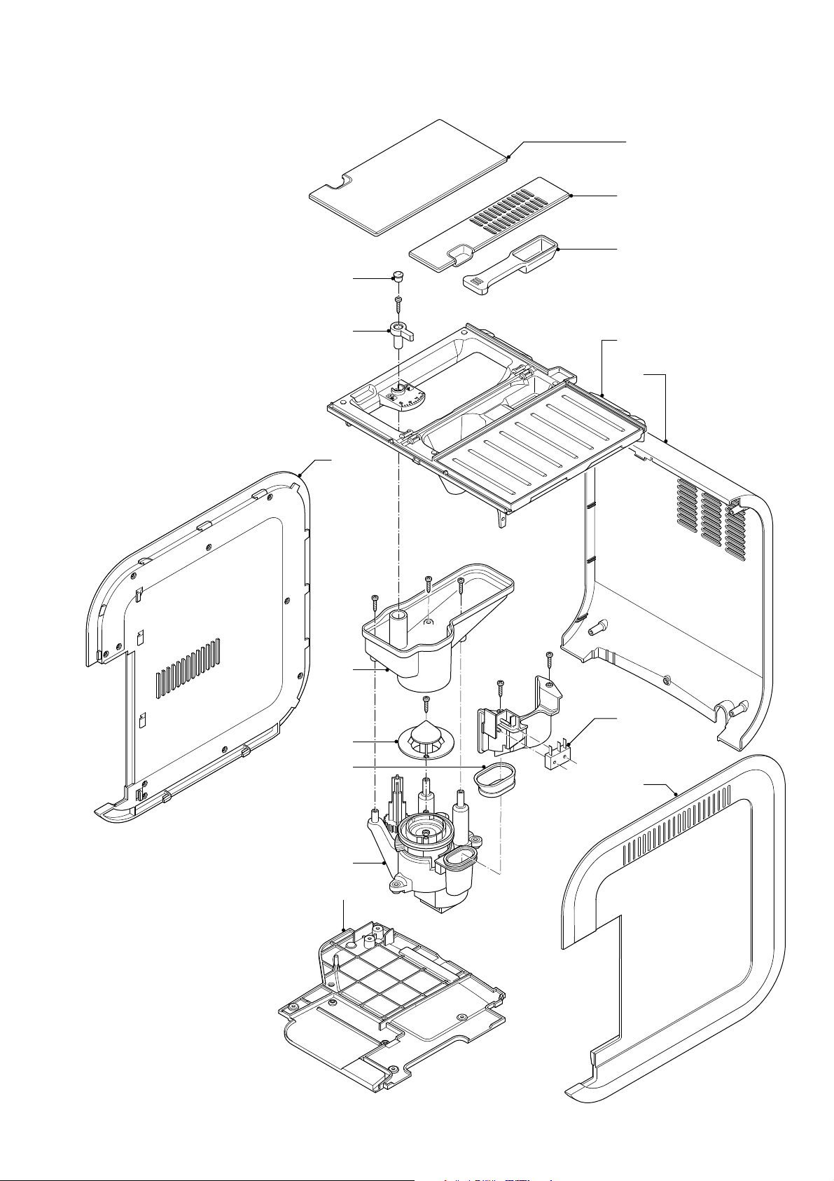
EXPLODED VIEW
HD5730/10
9
10
11
1
2
3
4
5
12
13
14
6
15
7
8
23-26
Page 24
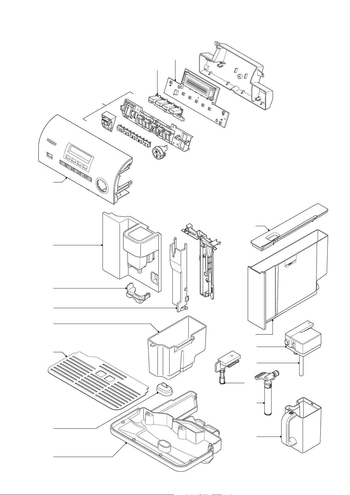
EXPLODED VIEW
16
HD5730/10
19
18
17
20
21
22
23
24
27
28
29
30
31
25
26
32
33
24-26
Page 25
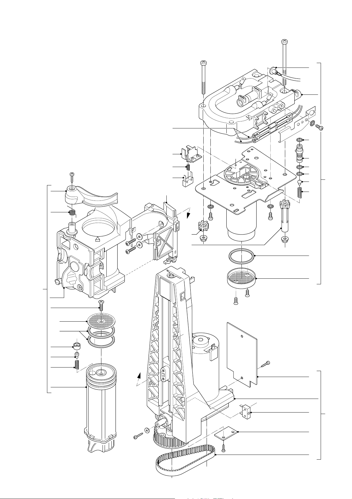
EXPLODED VIEW
HD5730/10
44
37
45
36
34
35
38
39
40
41
42
43
A
46
45
45
47
48
35
49
50
A
51
52
53
54
55
25-26
Page 26
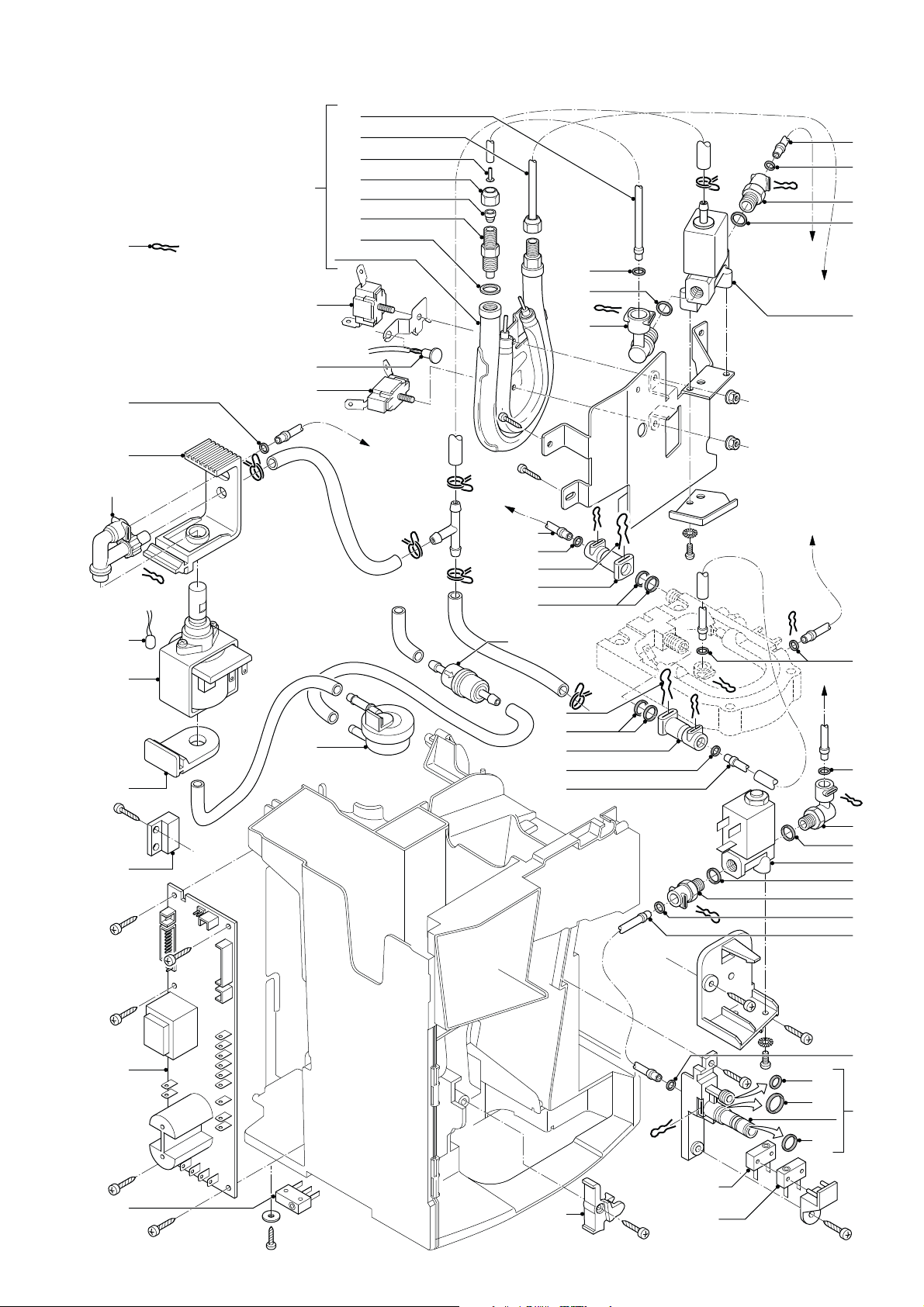
EXPLODED VIEW
56
57
72
73
44
73
65
66
67
68
69
70
71
57
75
77
HD5730/10
84
57
85
75
B
C
86
58
59
60
61
62
63
74
A
A
77
57
78
79
80
81
78
80
79
57
82
B
57
C
57
76
75
87
75
85
57
82
64
14
83
40
40
88
89
90
57
91
26-26
 Loading...