

Page 1

HD3
Service Manual
4535 612 34161 Rev A August 2005
CSIP Level 1
Copyright © 2005 Koninklijke Philips Electronics N.V. All rights reserved
About This Manual
Audience
Manual Format
Conventions in This Manual
This document and the information contained in it is strictly reserved for current Philips Medical
Systems (“Philips”) personnel, Philips licensed representatives, and Philips customers who have
purchased a valid service agreement for use by the customer’s designated in-house service
employee on equipment located at the customer’s designated site. Use of this document by
unauthorized persons is strictly prohibited. This document must be returned to Philips when the
user is no longer licensed and in any event upon Philips’ first written request.
This manual supports the field service maintenance and repair of the HD3 Ultrasound System.
The user of this document is a qualified ultrasound electronics technician who has completed
training classes on the system and its peripherals.
This manual is in Portable Document Format (PDF), for viewing on a laptop computer with
Acrobat Reader. A list of bookmarks functions as an additional table of contents. Those bookmarks, the table of contents, and cross-references use hypertext links to provide access to the
referenced information.
The following conventions are used in this manual:
• Hypertext links are blue.
• All procedures are numbered, and all subprocedures are lettered. You must complete steps
in the sequence they are presented to ensure reliable results.
Page 2

4535 612 34161 HD3 Service Manual Page 2
CSIP Level 1 About This Manual
• Bulleted lists indicate general information about a function or procedure. They do not imply
a sequential procedure.
• Control names and menu items or titles are spelled as they are on the system, and they
appear in bold text.
• Symbols appear as they appear on the system.
• An English system is assumed.
Service Manual Questions or Comments
Customer Assistance
If you have questions about the service manual, or you discover an error in the manual, contact
Philips Ultrasound Technical Communications:
• bothell.techpubs@philips.com
• Technical Communications, MS 964, at the address below
Various support locations around the world can provide customers technical assistance with the
ultrasound system. Customers should contact the representative or sales office from which they
purchased the system or the nearest Philips Ultrasound office.
Philips Ultrasound
22100 Bothell-Everett Highway
Bothell, WA 98021-8431
USA
425-487-7000 or 800-426-2670
www.medical.philips.com
Page 3

4535 612 34161 HD3 Service Manual Page 3
CSIP Level 1 About This Manual
“HD3”, “Chroma” and “Color Power Angio” are trademarks of Koninklijke Philips Electronics N.V.
Non-Philips product names may be trademarks or registered trademarks of their respective owners.
This document and the information contained in it is proprietary and confidential information of Philips Medical Systems (“Philips”)
and may not be reproduced, copied in whole or in part, adapted, modified, disclosed to others, or disseminated without the prior
written permission of the Philips Legal Department. Use of this document and the information contained in it is strictly reserved
for current Philips personnel and Philips customers who have a current and valid license from Philips for use by the customer’s
designated in-house service employee on equipment located at the customer’s designated site. Use of this document by unauthorized persons is strictly prohibited. Report violation of these requirements to the Philips Legal Department. This document must
be returned to Philips when the user is no longer licensed and in any event upon Philips’ first written request.
Philips provides this document without warranty of any kind, implied or expressed, including, but not limited to, the implied warranties of merchantability and fitness for a particular purpose.
Philips has taken care to ensure the accuracy of this document. However, Philips assumes no liability for errors or omissions and
reserves the right to make changes without further notice to any products herein to improve reliability, function, or design. Philips
may make improvements or changes in the products or programs described in this document at any time.
Page 4

4535 612 34161 HD3 Service Manual Page 4
CSIP Level 1 Contents
Contents
About This Manual . . . . . . . . . . . . . . . . . . . . . . . . . . . . . . . . . . . . . . . . . . . . . . . . . . . . . . . . . . . . . . . . . . . . . . . .1
Audience . . . . . . . . . . . . . . . . . . . . . . . . . . . . . . . . . . . . . . . . . . . . . . . . . . . . . . . . . . . . . . . . . . . . . . . . . . . . . . . . . . . . . . . 1
Manual Format . . . . . . . . . . . . . . . . . . . . . . . . . . . . . . . . . . . . . . . . . . . . . . . . . . . . . . . . . . . . . . . . . . . . . . . . . . . . . . . . . . 1
Conventions in This Manual . . . . . . . . . . . . . . . . . . . . . . . . . . . . . . . . . . . . . . . . . . . . . . . . . . . . . . . . . . . . . . . . . . . . . . . . 1
Service Manual Questions or Comments . . . . . . . . . . . . . . . . . . . . . . . . . . . . . . . . . . . . . . . . . . . . . . . . . . . . . . . . . . . . . 2
Customer Assistance . . . . . . . . . . . . . . . . . . . . . . . . . . . . . . . . . . . . . . . . . . . . . . . . . . . . . . . . . . . . . . . . . . . . . . . . . . . . . 2
General Information . . . . . . . . . . . . . . . . . . . . . . . . . . . . . . . . . . . . . . . . . . . . . . . . . . . . . . . . . . . . . . . . . . . . . .25
Introduction . . . . . . . . . . . . . . . . . . . . . . . . . . . . . . . . . . . . . . . . . . . . . . . . . . . . . . . . . . . . . . . . . . . . . . . . . . . . . . . . . . . . . . 25
More About This Manual . . . . . . . . . . . . . . . . . . . . . . . . . . . . . . . . . . . . . . . . . . . . . . . . . . . . . . . . . . . . . . . . . . . . . . . . . . . . 25
System Overview . . . . . . . . . . . . . . . . . . . . . . . . . . . . . . . . . . . . . . . . . . . . . . . . . . . . . . . . . . . . . . . . . . . . . . . . . . . . . . . . . . 27
Figure 1-1 HD3 Ultrasound System . . . . . . . . . . . . . . . . . . . . . . . . . . . . . . . . . . . . . . . . . . . . . . . . . . . . . . . . . . . . . . 28
Applications . . . . . . . . . . . . . . . . . . . . . . . . . . . . . . . . . . . . . . . . . . . . . . . . . . . . . . . . . . . . . . . . . . . . . . . . . . . . . . . . . . . 29
Modes . . . . . . . . . . . . . . . . . . . . . . . . . . . . . . . . . . . . . . . . . . . . . . . . . . . . . . . . . . . . . . . . . . . . . . . . . . . . . . . . . . . . . . . . 29
Transducers . . . . . . . . . . . . . . . . . . . . . . . . . . . . . . . . . . . . . . . . . . . . . . . . . . . . . . . . . . . . . . . . . . . . . . . . . . . . . . . . . . . 30
Languages . . . . . . . . . . . . . . . . . . . . . . . . . . . . . . . . . . . . . . . . . . . . . . . . . . . . . . . . . . . . . . . . . . . . . . . . . . . . . . . . . . . . . 30
Options . . . . . . . . . . . . . . . . . . . . . . . . . . . . . . . . . . . . . . . . . . . . . . . . . . . . . . . . . . . . . . . . . . . . . . . . . . . . . . . . . . . . . . . 31
Peripherals . . . . . . . . . . . . . . . . . . . . . . . . . . . . . . . . . . . . . . . . . . . . . . . . . . . . . . . . . . . . . . . . . . . . . . . . . . . . . . . . . . . . 32
Figure 1-2 HD3 Ultrasound System Image Printers and VCR . . . . . . . . . . . . . . . . . . . . . . . . . . . . . . . . . . . . . . . . . 33
Figure 1-3 HD3 Ultrasound System Data Media . . . . . . . . . . . . . . . . . . . . . . . . . . . . . . . . . . . . . . . . . . . . . . . . . . . . 34
Page 5

4535 612 34161 HD3 Service Manual Page 5
CSIP Level 1 Contents
Figure 1-4 HD3 Ultrasound System Foot Switch . . . . . . . . . . . . . . . . . . . . . . . . . . . . . . . . . . . . . . . . . . . . . . . . . . . 35
Physical Description . . . . . . . . . . . . . . . . . . . . . . . . . . . . . . . . . . . . . . . . . . . . . . . . . . . . . . . . . . . . . . . . . . . . . . . . . . . . . . . . 36
Cart . . . . . . . . . . . . . . . . . . . . . . . . . . . . . . . . . . . . . . . . . . . . . . . . . . . . . . . . . . . . . . . . . . . . . . . . . . . . . . . . . . . . . . . . . . 36
System Control Panel . . . . . . . . . . . . . . . . . . . . . . . . . . . . . . . . . . . . . . . . . . . . . . . . . . . . . . . . . . . . . . . . . . . . . . . . . . . . 36
Figure 1-5 HD3 Ultrasound System Control Panel . . . . . . . . . . . . . . . . . . . . . . . . . . . . . . . . . . . . . . . . . . . . . . . . . . 37
System Monitor . . . . . . . . . . . . . . . . . . . . . . . . . . . . . . . . . . . . . . . . . . . . . . . . . . . . . . . . . . . . . . . . . . . . . . . . . . . . . . . . 37
Ultrasound Components . . . . . . . . . . . . . . . . . . . . . . . . . . . . . . . . . . . . . . . . . . . . . . . . . . . . . . . . . . . . . . . . . . . . . . . . . 37
System Power Components . . . . . . . . . . . . . . . . . . . . . . . . . . . . . . . . . . . . . . . . . . . . . . . . . . . . . . . . . . . . . . . . . . . . . . . 38
Software and Data Storage Components . . . . . . . . . . . . . . . . . . . . . . . . . . . . . . . . . . . . . . . . . . . . . . . . . . . . . . . . . . . . 38
I/O Panel . . . . . . . . . . . . . . . . . . . . . . . . . . . . . . . . . . . . . . . . . . . . . . . . . . . . . . . . . . . . . . . . . . . . . . . . . . . . . . . . . . . . . . 39
Cables . . . . . . . . . . . . . . . . . . . . . . . . . . . . . . . . . . . . . . . . . . . . . . . . . . . . . . . . . . . . . . . . . . . . . . . . . . . . . . . . . . . . . . . . 39
Device Safety Requirements and Regulatory Compliance . . . . . . . . . . . . . . . . . . . . . . . . . . . . . . . . . . . . . . . . . . . . . . . . . . 39
Supplies and Accessories . . . . . . . . . . . . . . . . . . . . . . . . . . . . . . . . . . . . . . . . . . . . . . . . . . . . . . . . . . . . . . . . . . . . . . . . . . . . 40
Open Source Software License . . . . . . . . . . . . . . . . . . . . . . . . . . . . . . . . . . . . . . . . . . . . . . . . . . . . . . . . . . . . . . . . . . . . . . . 40
System Specifications . . . . . . . . . . . . . . . . . . . . . . . . . . . . . . . . . . . . . . . . . . . . . . . . . . . . . . . . . . . . . . . . . . . . .41
Introduction . . . . . . . . . . . . . . . . . . . . . . . . . . . . . . . . . . . . . . . . . . . . . . . . . . . . . . . . . . . . . . . . . . . . . . . . . . . . . . . . . . . . . . 41
Physical Specifications . . . . . . . . . . . . . . . . . . . . . . . . . . . . . . . . . . . . . . . . . . . . . . . . . . . . . . . . . . . . . . . . . . . . . . . . . . . . . . . 41
Electrical Specifications . . . . . . . . . . . . . . . . . . . . . . . . . . . . . . . . . . . . . . . . . . . . . . . . . . . . . . . . . . . . . . . . . . . . . . . . . . . . . . 41
Environmental Specifications . . . . . . . . . . . . . . . . . . . . . . . . . . . . . . . . . . . . . . . . . . . . . . . . . . . . . . . . . . . . . . . . . . . . . . . . . 42
System PC Specifications . . . . . . . . . . . . . . . . . . . . . . . . . . . . . . . . . . . . . . . . . . . . . . . . . . . . . . . . . . . . . . . . . . . . . . . . . . . . 42
Table 2-1 Embedded PC Hardware Specifications . . . . . . . . . . . . . . . . . . . . . . . . . . . . . . . . . . . . . . . . . . . . . . . . . . 42
Page 6

4535 612 34161 HD3 Service Manual Page 6
CSIP Level 1 Contents
Monitor Specifications . . . . . . . . . . . . . . . . . . . . . . . . . . . . . . . . . . . . . . . . . . . . . . . . . . . . . . . . . . . . . . . . . . . . . . . . . . . . . . 43
Image Formats . . . . . . . . . . . . . . . . . . . . . . . . . . . . . . . . . . . . . . . . . . . . . . . . . . . . . . . . . . . . . . . . . . . . . . . . . . . . . . . . . . . . 44
Table 2-2 Supported Image Formats . . . . . . . . . . . . . . . . . . . . . . . . . . . . . . . . . . . . . . . . . . . . . . . . . . . . . . . . . . . . . 44
Safety . . . . . . . . . . . . . . . . . . . . . . . . . . . . . . . . . . . . . . . . . . . . . . . . . . . . . . . . . . . . . . . . . . . . . . . . . . . . . . . . . .45
Introduction . . . . . . . . . . . . . . . . . . . . . . . . . . . . . . . . . . . . . . . . . . . . . . . . . . . . . . . . . . . . . . . . . . . . . . . . . . . . . . . . . . . . . . 45
About Safety Information . . . . . . . . . . . . . . . . . . . . . . . . . . . . . . . . . . . . . . . . . . . . . . . . . . . . . . . . . . . . . . . . . . . . . . . . . . . . 45
General Operating Safety . . . . . . . . . . . . . . . . . . . . . . . . . . . . . . . . . . . . . . . . . . . . . . . . . . . . . . . . . . . . . . . . . . . . . . . . . . . . 45
Electrical Safety . . . . . . . . . . . . . . . . . . . . . . . . . . . . . . . . . . . . . . . . . . . . . . . . . . . . . . . . . . . . . . . . . . . . . . . . . . . . . . . . . . . . 46
Avoiding EMI and RF . . . . . . . . . . . . . . . . . . . . . . . . . . . . . . . . . . . . . . . . . . . . . . . . . . . . . . . . . . . . . . . . . . . . . . . . . . . . 48
Mechanical Safety . . . . . . . . . . . . . . . . . . . . . . . . . . . . . . . . . . . . . . . . . . . . . . . . . . . . . . . . . . . . . . . . . . . . . . . . . . . . . . . . . . 49
General Equipment Protection . . . . . . . . . . . . . . . . . . . . . . . . . . . . . . . . . . . . . . . . . . . . . . . . . . . . . . . . . . . . . . . . . . . . . . . 50
About Electrostatic Discharge . . . . . . . . . . . . . . . . . . . . . . . . . . . . . . . . . . . . . . . . . . . . . . . . . . . . . . . . . . . . . . . . . . . . . 51
Symbols . . . . . . . . . . . . . . . . . . . . . . . . . . . . . . . . . . . . . . . . . . . . . . . . . . . . . . . . . . . . . . . . . . . . . . . . . . . . . . . . . . . . . . . . . . 52
Theory of Operation . . . . . . . . . . . . . . . . . . . . . . . . . . . . . . . . . . . . . . . . . . . . . . . . . . . . . . . . . . . . . . . . . . . . . .58
Introduction . . . . . . . . . . . . . . . . . . . . . . . . . . . . . . . . . . . . . . . . . . . . . . . . . . . . . . . . . . . . . . . . . . . . . . . . . . . . . . . . . . . . . . 58
System Architecture . . . . . . . . . . . . . . . . . . . . . . . . . . . . . . . . . . . . . . . . . . . . . . . . . . . . . . . . . . . . . . . . . . . . . . . . . . . . . . . . 58
Operating System . . . . . . . . . . . . . . . . . . . . . . . . . . . . . . . . . . . . . . . . . . . . . . . . . . . . . . . . . . . . . . . . . . . . . . . . . . . . . . . . . . 58
Functional Description . . . . . . . . . . . . . . . . . . . . . . . . . . . . . . . . . . . . . . . . . . . . . . . . . . . . . . . . . . . . . . . . . . . . . . . . . . . . . . 59
Figure 4-1 HD3 System Functional Block Diagram . . . . . . . . . . . . . . . . . . . . . . . . . . . . . . . . . . . . . . . . . . . . . . . . . . 60
Physical Functions . . . . . . . . . . . . . . . . . . . . . . . . . . . . . . . . . . . . . . . . . . . . . . . . . . . . . . . . . . . . . . . . . . . . . . . . . . . . . . . 61
System Power . . . . . . . . . . . . . . . . . . . . . . . . . . . . . . . . . . . . . . . . . . . . . . . . . . . . . . . . . . . . . . . . . . . . . . . . . . . . . . . . . . 61
Page 7

4535 612 34161 HD3 Service Manual Page 7
CSIP Level 1 Contents
Transducer Connector Assembly (TCA) . . . . . . . . . . . . . . . . . . . . . . . . . . . . . . . . . . . . . . . . . . . . . . . . . . . . . . . . . . . . 63
Front End (FE) Board . . . . . . . . . . . . . . . . . . . . . . . . . . . . . . . . . . . . . . . . . . . . . . . . . . . . . . . . . . . . . . . . . . . . . . . . . . . . 63
Beamformer (BF) . . . . . . . . . . . . . . . . . . . . . . . . . . . . . . . . . . . . . . . . . . . . . . . . . . . . . . . . . . . . . . . . . . . . . . . . . . . . . . . 63
Digital Scan Converter (DSC) . . . . . . . . . . . . . . . . . . . . . . . . . . . . . . . . . . . . . . . . . . . . . . . . . . . . . . . . . . . . . . . . . . . . . 63
PCC Board . . . . . . . . . . . . . . . . . . . . . . . . . . . . . . . . . . . . . . . . . . . . . . . . . . . . . . . . . . . . . . . . . . . . . . . . . . . . . . . . . . . . 64
E-box Backplane . . . . . . . . . . . . . . . . . . . . . . . . . . . . . . . . . . . . . . . . . . . . . . . . . . . . . . . . . . . . . . . . . . . . . . . . . . . . . . . . 65
Input/Output Panel . . . . . . . . . . . . . . . . . . . . . . . . . . . . . . . . . . . . . . . . . . . . . . . . . . . . . . . . . . . . . . . . . . . . . . . . . . . . . . 65
User Interface . . . . . . . . . . . . . . . . . . . . . . . . . . . . . . . . . . . . . . . . . . . . . . . . . . . . . . . . . . . . . . . . . . . . . . . . . . . . . . . . . . 65
Hard Disk Drive (HDD) . . . . . . . . . . . . . . . . . . . . . . . . . . . . . . . . . . . . . . . . . . . . . . . . . . . . . . . . . . . . . . . . . . . . . . . . . . 66
CD-RW . . . . . . . . . . . . . . . . . . . . . . . . . . . . . . . . . . . . . . . . . . . . . . . . . . . . . . . . . . . . . . . . . . . . . . . . . . . . . . . . . . . . . . . 66
Magneto-optical Disk (MOD) Drive . . . . . . . . . . . . . . . . . . . . . . . . . . . . . . . . . . . . . . . . . . . . . . . . . . . . . . . . . . . . . . . . 66
Flash Memory Stick . . . . . . . . . . . . . . . . . . . . . . . . . . . . . . . . . . . . . . . . . . . . . . . . . . . . . . . . . . . . . . . . . . . . . . . . . . . . . . 66
Installation . . . . . . . . . . . . . . . . . . . . . . . . . . . . . . . . . . . . . . . . . . . . . . . . . . . . . . . . . . . . . . . . . . . . . . . . . . . . . .67
Introduction . . . . . . . . . . . . . . . . . . . . . . . . . . . . . . . . . . . . . . . . . . . . . . . . . . . . . . . . . . . . . . . . . . . . . . . . . . . . . . . . . . . . . . 67
Installation Checklist . . . . . . . . . . . . . . . . . . . . . . . . . . . . . . . . . . . . . . . . . . . . . . . . . . . . . . . . . . . . . . . . . . . . . . . . . . . . . . . . 67
Inspecting the Installation Site . . . . . . . . . . . . . . . . . . . . . . . . . . . . . . . . . . . . . . . . . . . . . . . . . . . . . . . . . . . . . . . . . . . . . . . . 68
Checking Physical Access for Delivery and Installation . . . . . . . . . . . . . . . . . . . . . . . . . . . . . . . . . . . . . . . . . . . . . . . . . . 68
Checking Electrical and Environmental Requirements . . . . . . . . . . . . . . . . . . . . . . . . . . . . . . . . . . . . . . . . . . . . . . . . . . 69
Gathering Site Network (DICOM) Information . . . . . . . . . . . . . . . . . . . . . . . . . . . . . . . . . . . . . . . . . . . . . . . . . . . . . . 69
Uncrating and Unpacking the System . . . . . . . . . . . . . . . . . . . . . . . . . . . . . . . . . . . . . . . . . . . . . . . . . . . . . . . . . . . . . . . . . . . 70
Inspecting the Crate . . . . . . . . . . . . . . . . . . . . . . . . . . . . . . . . . . . . . . . . . . . . . . . . . . . . . . . . . . . . . . . . . . . . . . . . . . . . 70
Page 8

4535 612 34161 HD3 Service Manual Page 8
CSIP Level 1 Contents
Uncrating . . . . . . . . . . . . . . . . . . . . . . . . . . . . . . . . . . . . . . . . . . . . . . . . . . . . . . . . . . . . . . . . . . . . . . . . . . . . . . . . . . . . . 71
Inspecting the System . . . . . . . . . . . . . . . . . . . . . . . . . . . . . . . . . . . . . . . . . . . . . . . . . . . . . . . . . . . . . . . . . . . . . . . . . . . . . . . 71
➤ To inspect the system after uncrating . . . . . . . . . . . . . . . . . . . . . . . . . . . . . . . . . . . . . . . . . . . . . . . . . . . . . . . . . . . . 71
Assembling the System . . . . . . . . . . . . . . . . . . . . . . . . . . . . . . . . . . . . . . . . . . . . . . . . . . . . . . . . . . . . . . . . . . . . . . . . . . . . . . 72
Installing the Printers, VCR, and Footswitch . . . . . . . . . . . . . . . . . . . . . . . . . . . . . . . . . . . . . . . . . . . . . . . . . . . . . . . . . . 72
Installing the System Power Cord . . . . . . . . . . . . . . . . . . . . . . . . . . . . . . . . . . . . . . . . . . . . . . . . . . . . . . . . . . . . . . . . . . 72
Powering On and Configuring the System . . . . . . . . . . . . . . . . . . . . . . . . . . . . . . . . . . . . . . . . . . . . . . . . . . . . . . . . . . . . . . . 72
Verifying the Local Settings . . . . . . . . . . . . . . . . . . . . . . . . . . . . . . . . . . . . . . . . . . . . . . . . . . . . . . . . . . . . . . . . . . . . . . . 73
➤ To check or set the institution name . . . . . . . . . . . . . . . . . . . . . . . . . . . . . . . . . . . . . . . . . . . . . . . . . . . . . . . . . . . . 73
Figure 5-1 Setup Window (System) . . . . . . . . . . . . . . . . . . . . . . . . . . . . . . . . . . . . . . . . . . . . . . . . . . . . . . . . . . . . . . 74
➤ To verify or set the system time and date . . . . . . . . . . . . . . . . . . . . . . . . . . . . . . . . . . . . . . . . . . . . . . . . . . . . . . . . . 75
➤ To change the user interface language . . . . . . . . . . . . . . . . . . . . . . . . . . . . . . . . . . . . . . . . . . . . . . . . . . . . . . . . . . . . 75
Verifying the System Options . . . . . . . . . . . . . . . . . . . . . . . . . . . . . . . . . . . . . . . . . . . . . . . . . . . . . . . . . . . . . . . . . . . . . . 76
➤ To verify or activate system software options . . . . . . . . . . . . . . . . . . . . . . . . . . . . . . . . . . . . . . . . . . . . . . . . . . . . . 76
Figure 5-2 Setup Window (Option) . . . . . . . . . . . . . . . . . . . . . . . . . . . . . . . . . . . . . . . . . . . . . . . . . . . . . . . . . . . . . 77
Configuring the DICOM Feature . . . . . . . . . . . . . . . . . . . . . . . . . . . . . . . . . . . . . . . . . . . . . . . . . . . . . . . . . . . . . . . . . . . 78
➤ To configure the system DICOM parameters . . . . . . . . . . . . . . . . . . . . . . . . . . . . . . . . . . . . . . . . . . . . . . . . . . . . . . 78
Figure 5-3 Setup Window (DICOM) . . . . . . . . . . . . . . . . . . . . . . . . . . . . . . . . . . . . . . . . . . . . . . . . . . . . . . . . . . . . 79
➤ To identify the DICOM storage devices that the system will use . . . . . . . . . . . . . . . . . . . . . . . . . . . . . . . . . . . . . . 80
➤ To identify the DICOM printers that the system will use . . . . . . . . . . . . . . . . . . . . . . . . . . . . . . . . . . . . . . . . . . . . 80
Figure 5-4 System Network Settings Window (DICOM) . . . . . . . . . . . . . . . . . . . . . . . . . . . . . . . . . . . . . . . . . . . . 81
Page 9

4535 612 34161 HD3 Service Manual Page 9
CSIP Level 1 Contents
Figure 5-5 Server Configuration Window (DICOM) . . . . . . . . . . . . . . . . . . . . . . . . . . . . . . . . . . . . . . . . . . . . . . . 82
➤ To test the communication between the system and a server or a printer . . . . . . . . . . . . . . . . . . . . . . . . . . . . . . 83
➤ To configure the DICOM Log file . . . . . . . . . . . . . . . . . . . . . . . . . . . . . . . . . . . . . . . . . . . . . . . . . . . . . . . . . . . . . . . 83
Figure 5-6 DICOM Device Test Results Message Examples (DICOM) . . . . . . . . . . . . . . . . . . . . . . . . . . . . . . . . . 84
Figure 5-7 Setup Window (Admin) . . . . . . . . . . . . . . . . . . . . . . . . . . . . . . . . . . . . . . . . . . . . . . . . . . . . . . . . . . . . . . 85
Figure 5-8 DICOM Log Window . . . . . . . . . . . . . . . . . . . . . . . . . . . . . . . . . . . . . . . . . . . . . . . . . . . . . . . . . . . . . . . . 86
Configuring Other System Settings . . . . . . . . . . . . . . . . . . . . . . . . . . . . . . . . . . . . . . . . . . . . . . . . . . . . . . . . . . . . . . . . . 87
➤ To configure other system settings . . . . . . . . . . . . . . . . . . . . . . . . . . . . . . . . . . . . . . . . . . . . . . . . . . . . . . . . . . . . . . 87
Preparing the Peripherals . . . . . . . . . . . . . . . . . . . . . . . . . . . . . . . . . . . . . . . . . . . . . . . . . . . . . . . . . . . . . . . . . . . . . . . . . . . . 87
Checking System Functionality . . . . . . . . . . . . . . . . . . . . . . . . . . . . . . . . . . . . . . . . . . . . . . . . . . . . . . . . . . . . . . . . . . . . . . . . 87
Presenting the System . . . . . . . . . . . . . . . . . . . . . . . . . . . . . . . . . . . . . . . . . . . . . . . . . . . . . . . . . . . . . . . . . . . . . . . . . . . . . . 88
Physical Installation Procedures . . . . . . . . . . . . . . . . . . . . . . . . . . . . . . . . . . . . . . . . . . . . . . . . . . . . . . . . . . . . . . . . . . . . . . . 89
Figure 5-1 Installation Procedure List . . . . . . . . . . . . . . . . . . . . . . . . . . . . . . . . . . . . . . . . . . . . . . . . . . . . . . . . . . . . 89
Uncrating the HD3 Ultrasound System . . . . . . . . . . . . . . . . . . . . . . . . . . . . . . . . . . . . . . . . . . . . . . . . . . . . . . . . . . . . . . 90
Figure 5-2 Cutting the Poly Strapping Bands . . . . . . . . . . . . . . . . . . . . . . . . . . . . . . . . . . . . . . . . . . . . . . . . . . . . . . . 90
➤ To uncrate the HD3 Ultrasound System . . . . . . . . . . . . . . . . . . . . . . . . . . . . . . . . . . . . . . . . . . . . . . . . . . . . . . . . . . 90
Figure 5-3 Removing the Corrugated Top Cover . . . . . . . . . . . . . . . . . . . . . . . . . . . . . . . . . . . . . . . . . . . . . . . . . . . 91
Figure 5-4 Removing the Corrugated Wrap . . . . . . . . . . . . . . . . . . . . . . . . . . . . . . . . . . . . . . . . . . . . . . . . . . . . . . . 92
Figure 5-5 Removing the Ramp Bolts . . . . . . . . . . . . . . . . . . . . . . . . . . . . . . . . . . . . . . . . . . . . . . . . . . . . . . . . . . . . 93
Figure 5-6 Placing the Ramp . . . . . . . . . . . . . . . . . . . . . . . . . . . . . . . . . . . . . . . . . . . . . . . . . . . . . . . . . . . . . . . . . . . . 94
Figure 5-7 Removing the System Hold-down Brace . . . . . . . . . . . . . . . . . . . . . . . . . . . . . . . . . . . . . . . . . . . . . . . . . 95
Page 10

4535 612 34161 HD3 Service Manual Page 10
CSIP Level 1 Contents
Figure 5-8 Removing the Wheel Chock . . . . . . . . . . . . . . . . . . . . . . . . . . . . . . . . . . . . . . . . . . . . . . . . . . . . . . . . . . 96
Figure 5-9 Rotating the Rear Casters . . . . . . . . . . . . . . . . . . . . . . . . . . . . . . . . . . . . . . . . . . . . . . . . . . . . . . . . . . . . 97
Figure 5-10 Rolling the System Off the Pallet . . . . . . . . . . . . . . . . . . . . . . . . . . . . . . . . . . . . . . . . . . . . . . . . . . . . . . 98
Figure 5-11 Removing the Shipping Materials (Antistatic Bag and Monitor Support) . . . . . . . . . . . . . . . . . . . . . . . 99
Figure 5-12 Removing the Shipping Materials (Yoke Support) . . . . . . . . . . . . . . . . . . . . . . . . . . . . . . . . . . . . . . . . 100
Monitor Support Shipping Foam . . . . . . . . . . . . . . . . . . . . . . . . . . . . . . . . . . . . . . . . . . . . . . . . . . . . . . . . . . . . . . . . . . 101
Figure 5-13 Locking the Front Casters . . . . . . . . . . . . . . . . . . . . . . . . . . . . . . . . . . . . . . . . . . . . . . . . . . . . . . . . . . 101
➤ To install the monitor support shipping foam . . . . . . . . . . . . . . . . . . . . . . . . . . . . . . . . . . . . . . . . . . . . . . . . . . . . . 101
Figure 5-14 Tilting the Video Monitor . . . . . . . . . . . . . . . . . . . . . . . . . . . . . . . . . . . . . . . . . . . . . . . . . . . . . . . . . . . 102
Figure 5-15 Placing the Foam Monitor Support . . . . . . . . . . . . . . . . . . . . . . . . . . . . . . . . . . . . . . . . . . . . . . . . . . . . 103
Figure 5-16 Securing the Video Monitor . . . . . . . . . . . . . . . . . . . . . . . . . . . . . . . . . . . . . . . . . . . . . . . . . . . . . . . . . 104
Top-Mounted Color Printer . . . . . . . . . . . . . . . . . . . . . . . . . . . . . . . . . . . . . . . . . . . . . . . . . . . . . . . . . . . . . . . . . . . . . 105
Figure 5-17 Adjusting the Universal Peripheral Mounting Plate for the Color Printer . . . . . . . . . . . . . . . . . . . . . 105
➤ To install the color printer . . . . . . . . . . . . . . . . . . . . . . . . . . . . . . . . . . . . . . . . . . . . . . . . . . . . . . . . . . . . . . . . . . . . 105
Figure 5-18 Removing the Top Cover Access Plate Screws . . . . . . . . . . . . . . . . . . . . . . . . . . . . . . . . . . . . . . . . . . 106
Figure 5-19 Installing the Universal Peripheral Mounting Plate . . . . . . . . . . . . . . . . . . . . . . . . . . . . . . . . . . . . . . . . 107
Figure 5-20 Installing the Mounting Strap on the Universal Peripheral Mounting Plate . . . . . . . . . . . . . . . . . . . . . 108
Figure 5-21 Placing and Strapping the Color Printer to the Universal Peripheral Mounting Plate . . . . . . . . . . . . 109
Figure 5-22 Cabling the Color Printer to the HD3 System . . . . . . . . . . . . . . . . . . . . . . . . . . . . . . . . . . . . . . . . . . 110
Top-Mounted VCR . . . . . . . . . . . . . . . . . . . . . . . . . . . . . . . . . . . . . . . . . . . . . . . . . . . . . . . . . . . . . . . . . . . . . . . . . . . . . 111
Figure 5-23 Adjusting the Universal Peripheral Mounting Plate for the VCR . . . . . . . . . . . . . . . . . . . . . . . . . . . . 111
Page 11

4535 612 34161 HD3 Service Manual Page 11
CSIP Level 1 Contents
➤ To install the VCR . . . . . . . . . . . . . . . . . . . . . . . . . . . . . . . . . . . . . . . . . . . . . . . . . . . . . . . . . . . . . . . . . . . . . . . . . . 111
Figure 5-24 Removing the Top Cover Access Plate Screws . . . . . . . . . . . . . . . . . . . . . . . . . . . . . . . . . . . . . . . . . . 112
Figure 5-25 Installing the Universal Peripheral Mounting Plate . . . . . . . . . . . . . . . . . . . . . . . . . . . . . . . . . . . . . . . . 113
Figure 5-26 Installing the Mounting Strap on the Universal Peripheral Mounting Plate . . . . . . . . . . . . . . . . . . . . . 114
Figure 5-27 Placing and Strapping the VCR to the Universal Peripheral Mounting Plate . . . . . . . . . . . . . . . . . . . . 115
Figure 5-28 Cabling the VCR to the HD3 System . . . . . . . . . . . . . . . . . . . . . . . . . . . . . . . . . . . . . . . . . . . . . . . . . . 116
MOD Drive . . . . . . . . . . . . . . . . . . . . . . . . . . . . . . . . . . . . . . . . . . . . . . . . . . . . . . . . . . . . . . . . . . . . . . . . . . . . . . . . . . . 117
Figure 5-29 Connecting the USB Cable to the MOD Drive . . . . . . . . . . . . . . . . . . . . . . . . . . . . . . . . . . . . . . . . . . 117
➤ To install the MOD drive . . . . . . . . . . . . . . . . . . . . . . . . . . . . . . . . . . . . . . . . . . . . . . . . . . . . . . . . . . . . . . . . . . . . . 117
Figure 5-30 Connecting the USB Cable to the HD3 System . . . . . . . . . . . . . . . . . . . . . . . . . . . . . . . . . . . . . . . . . 118
Foot Switch . . . . . . . . . . . . . . . . . . . . . . . . . . . . . . . . . . . . . . . . . . . . . . . . . . . . . . . . . . . . . . . . . . . . . . . . . . . . . . . . . . . 119
Figure 5-31 Foot Switch Cabling . . . . . . . . . . . . . . . . . . . . . . . . . . . . . . . . . . . . . . . . . . . . . . . . . . . . . . . . . . . . . . . 119
➤ To install the foot switch . . . . . . . . . . . . . . . . . . . . . . . . . . . . . . . . . . . . . . . . . . . . . . . . . . . . . . . . . . . . . . . . . . . . . 119
Figure 5-32 Foot Switch Placement . . . . . . . . . . . . . . . . . . . . . . . . . . . . . . . . . . . . . . . . . . . . . . . . . . . . . . . . . . . . . 120
System Power Cord . . . . . . . . . . . . . . . . . . . . . . . . . . . . . . . . . . . . . . . . . . . . . . . . . . . . . . . . . . . . . . . . . . . . . . . . . . . . 121
Figure 5-33 Connecting the System Power Cord (Power Cord with Inline Filter) . . . . . . . . . . . . . . . . . . . . . . . . 121
➤ To install the system power cord . . . . . . . . . . . . . . . . . . . . . . . . . . . . . . . . . . . . . . . . . . . . . . . . . . . . . . . . . . . . . . 121
Figure 5-34 Connecting the System Power Cord (Power cord with Separate Inline Filter Power Adapter) . . . . 122
➤ To install the system power cord . . . . . . . . . . . . . . . . . . . . . . . . . . . . . . . . . . . . . . . . . . . . . . . . . . . . . . . . . . . . . . 122
B/W Printer Plate (No-Printer Systems) . . . . . . . . . . . . . . . . . . . . . . . . . . . . . . . . . . . . . . . . . . . . . . . . . . . . . . . . . . . . 123
Figure 5-35 B/W Printer Plate Storage . . . . . . . . . . . . . . . . . . . . . . . . . . . . . . . . . . . . . . . . . . . . . . . . . . . . . . . . . . 123
Page 12

4535 612 34161 HD3 Service Manual Page 12
CSIP Level 1 Contents
Performance Tests . . . . . . . . . . . . . . . . . . . . . . . . . . . . . . . . . . . . . . . . . . . . . . . . . . . . . . . . . . . . . . . . . . . . . . .124
Introduction . . . . . . . . . . . . . . . . . . . . . . . . . . . . . . . . . . . . . . . . . . . . . . . . . . . . . . . . . . . . . . . . . . . . . . . . . . . . . . . . . . . . . 124
Warnings and Cautions . . . . . . . . . . . . . . . . . . . . . . . . . . . . . . . . . . . . . . . . . . . . . . . . . . . . . . . . . . . . . . . . . . . . . . . . . . . . 124
Visual Inspection for Mechanical Integrity . . . . . . . . . . . . . . . . . . . . . . . . . . . . . . . . . . . . . . . . . . . . . . . . . . . . . . . . . . . . . 124
System Functionality . . . . . . . . . . . . . . . . . . . . . . . . . . . . . . . . . . . . . . . . . . . . . . . . . . . . . . . . . . . . . . . . . . . . . . . . . . . . . . . 125
Electrical Safety . . . . . . . . . . . . . . . . . . . . . . . . . . . . . . . . . . . . . . . . . . . . . . . . . . . . . . . . . . . . . . . . . . . . . . . . . . . . . . . . . . . 126
Chassis to Ground Resistance Test . . . . . . . . . . . . . . . . . . . . . . . . . . . . . . . . . . . . . . . . . . . . . . . . . . . . . . . . . . . . . . . . 127
Figure 6-1 Chassis to Ground Resistance Test Diagram . . . . . . . . . . . . . . . . . . . . . . . . . . . . . . . . . . . . . . . . . . . . 128
➤ To test the system for resistance between chassis and ground . . . . . . . . . . . . . . . . . . . . . . . . . . . . . . . . . . . . . . . 129
Ground Wire Leakage Current Test . . . . . . . . . . . . . . . . . . . . . . . . . . . . . . . . . . . . . . . . . . . . . . . . . . . . . . . . . . . . . . . 129
Figure 6-2 Ground Wire Leakage Current Test Diagram . . . . . . . . . . . . . . . . . . . . . . . . . . . . . . . . . . . . . . . . . . . 130
➤ To test the system ground wiring for leakage . . . . . . . . . . . . . . . . . . . . . . . . . . . . . . . . . . . . . . . . . . . . . . . . . . . . . 131
Transducer Tests . . . . . . . . . . . . . . . . . . . . . . . . . . . . . . . . . . . . . . . . . . . . . . . . . . . . . . . . . . . . . . . . . . . . . . . . . . . . . . 131
Figure 6-3 Transducer Leakage Current Test Diagram . . . . . . . . . . . . . . . . . . . . . . . . . . . . . . . . . . . . . . . . . . . . . 132
➤ To test transducer leakage current . . . . . . . . . . . . . . . . . . . . . . . . . . . . . . . . . . . . . . . . . . . . . . . . . . . . . . . . . . . . . 133
Figure 6-4 Transducer Isolation Leakage Current Test Diagram . . . . . . . . . . . . . . . . . . . . . . . . . . . . . . . . . . . . . . 135
➤ To test transducer isolation leakage current . . . . . . . . . . . . . . . . . . . . . . . . . . . . . . . . . . . . . . . . . . . . . . . . . . . . . . 136
Adjustments . . . . . . . . . . . . . . . . . . . . . . . . . . . . . . . . . . . . . . . . . . . . . . . . . . . . . . . . . . . . . . . . . . . . . . . . . . . .137
Introduction . . . . . . . . . . . . . . . . . . . . . . . . . . . . . . . . . . . . . . . . . . . . . . . . . . . . . . . . . . . . . . . . . . . . . . . . . . . . . . . . . . . . . 137
Adjusting the Monitor . . . . . . . . . . . . . . . . . . . . . . . . . . . . . . . . . . . . . . . . . . . . . . . . . . . . . . . . . . . . . . . . . . . . . . . . . . . . . 137
➤ To adjust the monitor brightness . . . . . . . . . . . . . . . . . . . . . . . . . . . . . . . . . . . . . . . . . . . . . . . . . . . . . . . . . . . . . . 137
Page 13

4535 612 34161 HD3 Service Manual Page 13
CSIP Level 1 Contents
Positioning the Monitor . . . . . . . . . . . . . . . . . . . . . . . . . . . . . . . . . . . . . . . . . . . . . . . . . . . . . . . . . . . . . . . . . . . . . . . . . . . . 137
Preventive Maintenance . . . . . . . . . . . . . . . . . . . . . . . . . . . . . . . . . . . . . . . . . . . . . . . . . . . . . . . . . . . . . . . . . .138
Introduction . . . . . . . . . . . . . . . . . . . . . . . . . . . . . . . . . . . . . . . . . . . . . . . . . . . . . . . . . . . . . . . . . . . . . . . . . . . . . . . . . . . . . 138
Warnings and Cautions . . . . . . . . . . . . . . . . . . . . . . . . . . . . . . . . . . . . . . . . . . . . . . . . . . . . . . . . . . . . . . . . . . . . . . . . . . . . 138
Exterior and Interior Assemblies . . . . . . . . . . . . . . . . . . . . . . . . . . . . . . . . . . . . . . . . . . . . . . . . . . . . . . . . . . . . . . . . . . 139
➤ To clean the trackball . . . . . . . . . . . . . . . . . . . . . . . . . . . . . . . . . . . . . . . . . . . . . . . . . . . . . . . . . . . . . . . . . . . . . . . . 139
Exterior Surfaces . . . . . . . . . . . . . . . . . . . . . . . . . . . . . . . . . . . . . . . . . . . . . . . . . . . . . . . . . . . . . . . . . . . . . . . . . . . . . . 140
Troubleshooting . . . . . . . . . . . . . . . . . . . . . . . . . . . . . . . . . . . . . . . . . . . . . . . . . . . . . . . . . . . . . . . . . . . . . . . . .141
Introduction . . . . . . . . . . . . . . . . . . . . . . . . . . . . . . . . . . . . . . . . . . . . . . . . . . . . . . . . . . . . . . . . . . . . . . . . . . . . . . . . . . . . . 141
Warnings and Cautions . . . . . . . . . . . . . . . . . . . . . . . . . . . . . . . . . . . . . . . . . . . . . . . . . . . . . . . . . . . . . . . . . . . . . . . . . . . . 141
All Troubleshooting Starts Here . . . . . . . . . . . . . . . . . . . . . . . . . . . . . . . . . . . . . . . . . . . . . . . . . . . . . . . . . . . . . . . . . . . . . 141
Table 9-1 Effective Problem-Solving Checklist . . . . . . . . . . . . . . . . . . . . . . . . . . . . . . . . . . . . . . . . . . . . . . . . . . . . 142
Clarifying Symptoms . . . . . . . . . . . . . . . . . . . . . . . . . . . . . . . . . . . . . . . . . . . . . . . . . . . . . . . . . . . . . . . . . . . . . . . . . . . . 142
Re-creating a Problem . . . . . . . . . . . . . . . . . . . . . . . . . . . . . . . . . . . . . . . . . . . . . . . . . . . . . . . . . . . . . . . . . . . . . . . . . . 143
Isolating Causes . . . . . . . . . . . . . . . . . . . . . . . . . . . . . . . . . . . . . . . . . . . . . . . . . . . . . . . . . . . . . . . . . . . . . . . . . . . . . . . 143
Developing a Solution . . . . . . . . . . . . . . . . . . . . . . . . . . . . . . . . . . . . . . . . . . . . . . . . . . . . . . . . . . . . . . . . . . . . . . . . . . . 145
Implementing a Solution . . . . . . . . . . . . . . . . . . . . . . . . . . . . . . . . . . . . . . . . . . . . . . . . . . . . . . . . . . . . . . . . . . . . . . . . . 145
Verifying Corrective Actions . . . . . . . . . . . . . . . . . . . . . . . . . . . . . . . . . . . . . . . . . . . . . . . . . . . . . . . . . . . . . . . . . . . . . 146
Returning the System to Service . . . . . . . . . . . . . . . . . . . . . . . . . . . . . . . . . . . . . . . . . . . . . . . . . . . . . . . . . . . . . . . . . . 147
Symptoms, Causes, and Corrective Actions . . . . . . . . . . . . . . . . . . . . . . . . . . . . . . . . . . . . . . . . . . . . . . . . . . . . . . . . . . . . 147
Disk is Full . . . . . . . . . . . . . . . . . . . . . . . . . . . . . . . . . . . . . . . . . . . . . . . . . . . . . . . . . . . . . . . . . . . . . . . . . . . . . . . . . . . . 147
Page 14

4535 612 34161 HD3 Service Manual Page 14
CSIP Level 1 Contents
Checking for EMI and RFI . . . . . . . . . . . . . . . . . . . . . . . . . . . . . . . . . . . . . . . . . . . . . . . . . . . . . . . . . . . . . . . . . . . . . . . . 147
System Hangs or Crashes . . . . . . . . . . . . . . . . . . . . . . . . . . . . . . . . . . . . . . . . . . . . . . . . . . . . . . . . . . . . . . . . . . . . . . . 148
DICOM/Network Failures . . . . . . . . . . . . . . . . . . . . . . . . . . . . . . . . . . . . . . . . . . . . . . . . . . . . . . . . . . . . . . . . . . . . . . . 149
Backing Up and Restoring . . . . . . . . . . . . . . . . . . . . . . . . . . . . . . . . . . . . . . . . . . . . . . . . . . . . . . . . . . . . . . . . . . . . . . . . . . 151
Loading Software and Drivers . . . . . . . . . . . . . . . . . . . . . . . . . . . . . . . . . . . . . . . . . . . . . . . . . . . . . . . . . . . . . . . . . . . . . . . 151
Managing System Options . . . . . . . . . . . . . . . . . . . . . . . . . . . . . . . . . . . . . . . . . . . . . . . . . . . . . . . . . . . . . . . . . . . . . . . . . . 151
Viewing System Information and Logs . . . . . . . . . . . . . . . . . . . . . . . . . . . . . . . . . . . . . . . . . . . . . . . . . . . . . . . . . . . . . . . . . 152
➤ To display system information . . . . . . . . . . . . . . . . . . . . . . . . . . . . . . . . . . . . . . . . . . . . . . . . . . . . . . . . . . . . . . . . . 153
➤ To display the keystroke or DICOM log . . . . . . . . . . . . . . . . . . . . . . . . . . . . . . . . . . . . . . . . . . . . . . . . . . . . . . . . . 153
Disassembly . . . . . . . . . . . . . . . . . . . . . . . . . . . . . . . . . . . . . . . . . . . . . . . . . . . . . . . . . . . . . . . . . . . . . . . . . . . .154
Introduction . . . . . . . . . . . . . . . . . . . . . . . . . . . . . . . . . . . . . . . . . . . . . . . . . . . . . . . . . . . . . . . . . . . . . . . . . . . . . . . . . . . . . 154
Warnings and Cautions . . . . . . . . . . . . . . . . . . . . . . . . . . . . . . . . . . . . . . . . . . . . . . . . . . . . . . . . . . . . . . . . . . . . . . . . . . . . 154
Disassembly (Removal) Procedures . . . . . . . . . . . . . . . . . . . . . . . . . . . . . . . . . . . . . . . . . . . . . . . . . . . . . . . . . . . . . . . . . . . 155
Figure 10-1 Disassembly Procedure List (1 of 2) . . . . . . . . . . . . . . . . . . . . . . . . . . . . . . . . . . . . . . . . . . . . . . . . . . 155
Figure 10-2 Disassembly Procedure List (2 of 2) . . . . . . . . . . . . . . . . . . . . . . . . . . . . . . . . . . . . . . . . . . . . . . . . . 156
System Enclosures . . . . . . . . . . . . . . . . . . . . . . . . . . . . . . . . . . . . . . . . . . . . . . . . . . . . . . . . . . . . . . . . . . . . . . . . . . . . . 157
Figure 10-3 Removing the Left Side Enclosure . . . . . . . . . . . . . . . . . . . . . . . . . . . . . . . . . . . . . . . . . . . . . . . . . . . . 157
➤ To remove the system enclosures . . . . . . . . . . . . . . . . . . . . . . . . . . . . . . . . . . . . . . . . . . . . . . . . . . . . . . . . . . . . . . 157
Figure 10-4 Removing the Right Side Enclosure . . . . . . . . . . . . . . . . . . . . . . . . . . . . . . . . . . . . . . . . . . . . . . . . . . . 158
Figure 10-5 Removing the Front Enclosure . . . . . . . . . . . . . . . . . . . . . . . . . . . . . . . . . . . . . . . . . . . . . . . . . . . . . . . 159
Video Monitor . . . . . . . . . . . . . . . . . . . . . . . . . . . . . . . . . . . . . . . . . . . . . . . . . . . . . . . . . . . . . . . . . . . . . . . . . . . . . . . . 160
Page 15

4535 612 34161 HD3 Service Manual Page 15
CSIP Level 1 Contents
Figure 10-6 Removing the Video Monitor . . . . . . . . . . . . . . . . . . . . . . . . . . . . . . . . . . . . . . . . . . . . . . . . . . . . . . . . 160
➤ To remove the system monitor . . . . . . . . . . . . . . . . . . . . . . . . . . . . . . . . . . . . . . . . . . . . . . . . . . . . . . . . . . . . . . . . 160
Figure 10-7 Disconnecting the Video Monitor Cables . . . . . . . . . . . . . . . . . . . . . . . . . . . . . . . . . . . . . . . . . . . . . . 161
Control Panel . . . . . . . . . . . . . . . . . . . . . . . . . . . . . . . . . . . . . . . . . . . . . . . . . . . . . . . . . . . . . . . . . . . . . . . . . . . . . . . . . 162
Figure 10-8 Removing the Top Control Panel Enclosure . . . . . . . . . . . . . . . . . . . . . . . . . . . . . . . . . . . . . . . . . . . . 162
➤ To remove the control panel, trackball assembly, keyboard assembly, and splitter board . . . . . . . . . . . . . . . . . . 162
Figure 10-9 Tilting the Top Control Panel Enclosure . . . . . . . . . . . . . . . . . . . . . . . . . . . . . . . . . . . . . . . . . . . . . . . 163
Figure 10-10 Disconnecting the Control Panel Cables . . . . . . . . . . . . . . . . . . . . . . . . . . . . . . . . . . . . . . . . . . . . . . 164
Figure 10-11 Removing the Trackball Assembly . . . . . . . . . . . . . . . . . . . . . . . . . . . . . . . . . . . . . . . . . . . . . . . . . . . 165
Figure 10-12 Removing the Keyboard Assembly . . . . . . . . . . . . . . . . . . . . . . . . . . . . . . . . . . . . . . . . . . . . . . . . . . . 166
Figure 10-13 Removing the Splitter Board . . . . . . . . . . . . . . . . . . . . . . . . . . . . . . . . . . . . . . . . . . . . . . . . . . . . . . . 167
VCR or Color Printer . . . . . . . . . . . . . . . . . . . . . . . . . . . . . . . . . . . . . . . . . . . . . . . . . . . . . . . . . . . . . . . . . . . . . . . . . . 168
Figure 10-14 Removing the VCR or the Color Printer . . . . . . . . . . . . . . . . . . . . . . . . . . . . . . . . . . . . . . . . . . . . . . 168
➤ To remove the VCR or the color printer . . . . . . . . . . . . . . . . . . . . . . . . . . . . . . . . . . . . . . . . . . . . . . . . . . . . . . . . 168
Universal Peripheral Mounting Plate . . . . . . . . . . . . . . . . . . . . . . . . . . . . . . . . . . . . . . . . . . . . . . . . . . . . . . . . . . . . . . . 169
Figure 10-15 Removing the Universal Peripheral Mounting Plate . . . . . . . . . . . . . . . . . . . . . . . . . . . . . . . . . . . . . . 169
➤ To remove the universal peripheral mounting plate . . . . . . . . . . . . . . . . . . . . . . . . . . . . . . . . . . . . . . . . . . . . . . . . 169
Peripheral Bay (B/W Printer, Printer Bay, CD/Hard Drive Rack, and Power Transformer) . . . . . . . . . . . . . . . . . . . . 170
Figure 10-16 Peripheral Bay Components . . . . . . . . . . . . . . . . . . . . . . . . . . . . . . . . . . . . . . . . . . . . . . . . . . . . . . . . 170
➤ To remove the B/W printer, CD/Hard drive rack, power transformer, and printer bay . . . . . . . . . . . . . . . . . . . 170
Figure 10-17 Disconnecting the B/W Printer Cables and Removing the Printer Retaining Bracket . . . . . . . . . . . 171
Page 16

4535 612 34161 HD3 Service Manual Page 16
CSIP Level 1 Contents
Figure 10-18 Disconnecting the Drive Cables and Removing the Drive Rack Assembly . . . . . . . . . . . . . . . . . . . 172
Figure 10-19 Removing the B/W Printer Bay . . . . . . . . . . . . . . . . . . . . . . . . . . . . . . . . . . . . . . . . . . . . . . . . . . . . . 173
Figure 10-20 Power Transformer Cable Tie . . . . . . . . . . . . . . . . . . . . . . . . . . . . . . . . . . . . . . . . . . . . . . . . . . . . . . 174
Figure 10-21 Sliding the Transformer Back . . . . . . . . . . . . . . . . . . . . . . . . . . . . . . . . . . . . . . . . . . . . . . . . . . . . . . . 175
Figure 10-22 Removing the Power I/O Box . . . . . . . . . . . . . . . . . . . . . . . . . . . . . . . . . . . . . . . . . . . . . . . . . . . . . . 176
Figure 10-23 Removing the Power Transformer . . . . . . . . . . . . . . . . . . . . . . . . . . . . . . . . . . . . . . . . . . . . . . . . . . . 177
E-box Bay (E-box Assembly, Transducer Connector Assembly, E-box Boards, Power Supply and Cooling Fans) . . 178
Figure 10-24 E-box Bay Components . . . . . . . . . . . . . . . . . . . . . . . . . . . . . . . . . . . . . . . . . . . . . . . . . . . . . . . . . . . 178
➤ To remove the E-box assembly, transducer connector assembly, E-box boards, power supply and cooling fans 178
Figure 10-25 Removing the E-box Rear Shield . . . . . . . . . . . . . . . . . . . . . . . . . . . . . . . . . . . . . . . . . . . . . . . . . . . . 179
Figure 10-26 Disconnecting the Power Supply Power Cord . . . . . . . . . . . . . . . . . . . . . . . . . . . . . . . . . . . . . . . . . 180
Figure 10-27 Removing the Power Supply . . . . . . . . . . . . . . . . . . . . . . . . . . . . . . . . . . . . . . . . . . . . . . . . . . . . . . . . 181
Figure 10-28 Removing the BFC Board . . . . . . . . . . . . . . . . . . . . . . . . . . . . . . . . . . . . . . . . . . . . . . . . . . . . . . . . . . 182
Figure 10-29 Removing the FE, BF and DSC Boards . . . . . . . . . . . . . . . . . . . . . . . . . . . . . . . . . . . . . . . . . . . . . . . . 183
Figure 10-30 Removing the PCC Board . . . . . . . . . . . . . . . . . . . . . . . . . . . . . . . . . . . . . . . . . . . . . . . . . . . . . . . . . 184
Figure 10-31 Removing the Transducer Connector Assembly (TCA) . . . . . . . . . . . . . . . . . . . . . . . . . . . . . . . . . . 185
Figure 10-32 Removing the E-box Assembly . . . . . . . . . . . . . . . . . . . . . . . . . . . . . . . . . . . . . . . . . . . . . . . . . . . . . . 186
Figure 10-33 Removing the Backplane Board Shield . . . . . . . . . . . . . . . . . . . . . . . . . . . . . . . . . . . . . . . . . . . . . . . . 187
Figure 10-34 Removing the Backplane Board . . . . . . . . . . . . . . . . . . . . . . . . . . . . . . . . . . . . . . . . . . . . . . . . . . . . . 188
Figure 10-35 Removing the E-box Cooling Fans . . . . . . . . . . . . . . . . . . . . . . . . . . . . . . . . . . . . . . . . . . . . . . . . . . . 189
Rear I/O Panel Assembly . . . . . . . . . . . . . . . . . . . . . . . . . . . . . . . . . . . . . . . . . . . . . . . . . . . . . . . . . . . . . . . . . . . . . . . . 190
Page 17

4535 612 34161 HD3 Service Manual Page 17
CSIP Level 1 Contents
Figure 10-36 Removing the Left and Right Side Enclosures . . . . . . . . . . . . . . . . . . . . . . . . . . . . . . . . . . . . . . . . . . 190
➤ To remove the Rear I/O panel assembly . . . . . . . . . . . . . . . . . . . . . . . . . . . . . . . . . . . . . . . . . . . . . . . . . . . . . . . . . 190
Figure 10-37 Removing the Rear I/O Panel . . . . . . . . . . . . . . . . . . . . . . . . . . . . . . . . . . . . . . . . . . . . . . . . . . . . . . . 191
Figure 10-38 Disconnecting the Rear I/O Panel Assembly PCB Cables . . . . . . . . . . . . . . . . . . . . . . . . . . . . . . . . . 192
Figure 10-39 Removing the Rear I/O Panel Assembly PCB . . . . . . . . . . . . . . . . . . . . . . . . . . . . . . . . . . . . . . . . . . 193
Power I/O Box . . . . . . . . . . . . . . . . . . . . . . . . . . . . . . . . . . . . . . . . . . . . . . . . . . . . . . . . . . . . . . . . . . . . . . . . . . . . . . . . 194
Figure 10-40 Removing the Left and Right Side Enclosures . . . . . . . . . . . . . . . . . . . . . . . . . . . . . . . . . . . . . . . . . . 194
➤ To remove the Power I/O box . . . . . . . . . . . . . . . . . . . . . . . . . . . . . . . . . . . . . . . . . . . . . . . . . . . . . . . . . . . . . . . . 194
Figure 10-41 Disconnecting the Power Supply Power Cord . . . . . . . . . . . . . . . . . . . . . . . . . . . . . . . . . . . . . . . . . 195
Figure 10-42 Cutting the Cable Ties on the Power Cables . . . . . . . . . . . . . . . . . . . . . . . . . . . . . . . . . . . . . . . . . . 196
Figure 10-43 Removing the Power I/O Box . . . . . . . . . . . . . . . . . . . . . . . . . . . . . . . . . . . . . . . . . . . . . . . . . . . . . . 197
Lift Column Gas Strut . . . . . . . . . . . . . . . . . . . . . . . . . . . . . . . . . . . . . . . . . . . . . . . . . . . . . . . . . . . . . . . . . . . . . . . . . . 198
Figure 10-44 Lowering the Control Panel . . . . . . . . . . . . . . . . . . . . . . . . . . . . . . . . . . . . . . . . . . . . . . . . . . . . . . . . 198
➤ To remove the lift column gas strut . . . . . . . . . . . . . . . . . . . . . . . . . . . . . . . . . . . . . . . . . . . . . . . . . . . . . . . . . . . . 198
Figure 10-45 Removing the Gas Strut from the Ball Stud . . . . . . . . . . . . . . . . . . . . . . . . . . . . . . . . . . . . . . . . . . . . 199
Figure 10-46 Removing the Gas Strut from the Lock Bracket . . . . . . . . . . . . . . . . . . . . . . . . . . . . . . . . . . . . . . . . 200
Figure 10-47 Removing the Gas Strut Mount Access Panel . . . . . . . . . . . . . . . . . . . . . . . . . . . . . . . . . . . . . . . . . . 201
Figure 10-48 Installing the Gas Strut into the Lock Bracket . . . . . . . . . . . . . . . . . . . . . . . . . . . . . . . . . . . . . . . . . . 202
Figure 10-49 Inserting the Gas Strut onto the Ball Stud . . . . . . . . . . . . . . . . . . . . . . . . . . . . . . . . . . . . . . . . . . . . . 203
System Casters . . . . . . . . . . . . . . . . . . . . . . . . . . . . . . . . . . . . . . . . . . . . . . . . . . . . . . . . . . . . . . . . . . . . . . . . . . . . . . . . 204
Figure 10-50 Preparing the System for Caster Replacement . . . . . . . . . . . . . . . . . . . . . . . . . . . . . . . . . . . . . . . . . 204
Page 18

4535 612 34161 HD3 Service Manual Page 18
CSIP Level 1 Contents
➤ To remove a system casters . . . . . . . . . . . . . . . . . . . . . . . . . . . . . . . . . . . . . . . . . . . . . . . . . . . . . . . . . . . . . . . . . . 204
Figure 10-51 Tipping the System to Remove the Rear Casters . . . . . . . . . . . . . . . . . . . . . . . . . . . . . . . . . . . . . . . 205
Figure 10-52 Tipping the System to Remove the Front Casters . . . . . . . . . . . . . . . . . . . . . . . . . . . . . . . . . . . . . . 206
Crating the HD3 Ultrasound System . . . . . . . . . . . . . . . . . . . . . . . . . . . . . . . . . . . . . . . . . . . . . . . . . . . . . . . . . . . . . . . 207
Figure 10-53 Locking the Front Casters . . . . . . . . . . . . . . . . . . . . . . . . . . . . . . . . . . . . . . . . . . . . . . . . . . . . . . . . . 207
➤ To crate the HD3 Ultrasound System . . . . . . . . . . . . . . . . . . . . . . . . . . . . . . . . . . . . . . . . . . . . . . . . . . . . . . . . . . . 207
Figure 10-54 Raising the Control Panel . . . . . . . . . . . . . . . . . . . . . . . . . . . . . . . . . . . . . . . . . . . . . . . . . . . . . . . . . . 208
Figure 10-55 Placing the Foam Yoke Support . . . . . . . . . . . . . . . . . . . . . . . . . . . . . . . . . . . . . . . . . . . . . . . . . . . . . 209
Figure 10-56 Lowering the Control Panel . . . . . . . . . . . . . . . . . . . . . . . . . . . . . . . . . . . . . . . . . . . . . . . . . . . . . . . . 210
Figure 10-57 Tilting the Video Monitor . . . . . . . . . . . . . . . . . . . . . . . . . . . . . . . . . . . . . . . . . . . . . . . . . . . . . . . . . . 211
Figure 10-58 Placing the Foam Monitor Support . . . . . . . . . . . . . . . . . . . . . . . . . . . . . . . . . . . . . . . . . . . . . . . . . . . 212
Figure 10-59 Securing the Video Monitor . . . . . . . . . . . . . . . . . . . . . . . . . . . . . . . . . . . . . . . . . . . . . . . . . . . . . . . . 213
Figure 10-60 Fastening the Two Foam Supports Together . . . . . . . . . . . . . . . . . . . . . . . . . . . . . . . . . . . . . . . . . . . 214
Figure 10-61 Covering the System with an Antistatic Bag . . . . . . . . . . . . . . . . . . . . . . . . . . . . . . . . . . . . . . . . . . . 215
Figure 10-62 Placing the Ramp . . . . . . . . . . . . . . . . . . . . . . . . . . . . . . . . . . . . . . . . . . . . . . . . . . . . . . . . . . . . . . . . . 216
Figure 10-63 Loading the System onto the Crate . . . . . . . . . . . . . . . . . . . . . . . . . . . . . . . . . . . . . . . . . . . . . . . . . . 217
Figure 10-64 Rotating the Rear Casters . . . . . . . . . . . . . . . . . . . . . . . . . . . . . . . . . . . . . . . . . . . . . . . . . . . . . . . . . 218
Figure 10-65 Placing the Wheel Chock . . . . . . . . . . . . . . . . . . . . . . . . . . . . . . . . . . . . . . . . . . . . . . . . . . . . . . . . . . 219
Figure 10-66 Placing the System Hold-Down Brace . . . . . . . . . . . . . . . . . . . . . . . . . . . . . . . . . . . . . . . . . . . . . . . . 220
Figure 10-67 Mounting the Ramp to the Crate . . . . . . . . . . . . . . . . . . . . . . . . . . . . . . . . . . . . . . . . . . . . . . . . . . . . 221
Figure 10-68 Placing the Corrugated Wrap . . . . . . . . . . . . . . . . . . . . . . . . . . . . . . . . . . . . . . . . . . . . . . . . . . . . . . 222
Page 19

4535 612 34161 HD3 Service Manual Page 19
CSIP Level 1 Contents
Figure 10-69 Placing the Corrugated Top Cover . . . . . . . . . . . . . . . . . . . . . . . . . . . . . . . . . . . . . . . . . . . . . . . . . . 223
Figure 10-70 Banding the System Crate . . . . . . . . . . . . . . . . . . . . . . . . . . . . . . . . . . . . . . . . . . . . . . . . . . . . . . . . . 224
Cabling . . . . . . . . . . . . . . . . . . . . . . . . . . . . . . . . . . . . . . . . . . . . . . . . . . . . . . . . . . . . . . . . . . . . . . . . . . . . . . . .225
Introduction . . . . . . . . . . . . . . . . . . . . . . . . . . . . . . . . . . . . . . . . . . . . . . . . . . . . . . . . . . . . . . . . . . . . . . . . . . . . . . . . . . . . . 225
System Cabling Diagrams . . . . . . . . . . . . . . . . . . . . . . . . . . . . . . . . . . . . . . . . . . . . . . . . . . . . . . . . . . . . . . . . . . . . . . . . . . 225
Cable Part Numbers . . . . . . . . . . . . . . . . . . . . . . . . . . . . . . . . . . . . . . . . . . . . . . . . . . . . . . . . . . . . . . . . . . . . . . . . . . . . . . . 225
System Connectors . . . . . . . . . . . . . . . . . . . . . . . . . . . . . . . . . . . . . . . . . . . . . . . . . . . . . . . . . . . . . . . . . . . . . . . . . . . . . . . 225
Figure 11-1 HD3 Ultrasound System Signal Interconnect Diagram . . . . . . . . . . . . . . . . . . . . . . . . . . . . . . . . . . . . 226
Figure 11-2 HD3 Ultrasound System Power Distribution Diagram . . . . . . . . . . . . . . . . . . . . . . . . . . . . . . . . . . . . 227
Cable Parts List . . . . . . . . . . . . . . . . . . . . . . . . . . . . . . . . . . . . . . . . . . . . . . . . . . . . . . . . . . . . . . . . . . . . . . . . . . . . . . . . . . . 228
Table 11-1 HD3 System Signal and Power Cable Part Numbers . . . . . . . . . . . . . . . . . . . . . . . . . . . . . . . . . . . . . . 228
Peripheral Cabling Diagrams . . . . . . . . . . . . . . . . . . . . . . . . . . . . . . . . . . . . . . . . . . . . . . . . . . . . . . . . . . . . . . . . . . . . . . . . 234
Figure 11-1 Sony UP-895MD B/W Printer Cabling Diagram . . . . . . . . . . . . . . . . . . . . . . . . . . . . . . . . . . . . . . . . . 234
Figure 11-2 Sony UP-21MD Color Printer Cabling Diagram . . . . . . . . . . . . . . . . . . . . . . . . . . . . . . . . . . . . . . . . . 235
Figure 11-3 Mitsubishi HS-MD3000UA/EA VCR Cabling Diagram . . . . . . . . . . . . . . . . . . . . . . . . . . . . . . . . . . . . . 236
System Connector Illustrations . . . . . . . . . . . . . . . . . . . . . . . . . . . . . . . . . . . . . . . . . . . . . . . . . . . . . . . . . . . . . . . . . . . . . . 237
Figure 11-4 HD3 System Connector Locations (Front Panel) . . . . . . . . . . . . . . . . . . . . . . . . . . . . . . . . . . . . . . . . 237
Figure 11-5 HD3 System Connector Locations (Rear I/O Panel) . . . . . . . . . . . . . . . . . . . . . . . . . . . . . . . . . . . . . . 238
Figure 11-6 HD3 System Connector Locations (Power Connectors) . . . . . . . . . . . . . . . . . . . . . . . . . . . . . . . . . . 239
Figure 11-7 HD3 System Connector Locations (Power I/O Box Connectors) . . . . . . . . . . . . . . . . . . . . . . . . . . . 240
Figure 11-8 HD3 Video Monitor PCB Cable Connector Locations . . . . . . . . . . . . . . . . . . . . . . . . . . . . . . . . . . . . 241
Page 20

4535 612 34161 HD3 Service Manual Page 20
CSIP Level 1 Contents
Figure 11-9 HD3 Control Panel PCB Cable Connector Locations (Splitter Board) . . . . . . . . . . . . . . . . . . . . . . . 242
Figure 11-10 HD3 Rear I/O PCB Internal Cable Connector Locations (Side View) . . . . . . . . . . . . . . . . . . . . . . . 243
Figure 11-11 HD3 PCC PCB Cable Connector Locations . . . . . . . . . . . . . . . . . . . . . . . . . . . . . . . . . . . . . . . . . . . 244
Change History . . . . . . . . . . . . . . . . . . . . . . . . . . . . . . . . . . . . . . . . . . . . . . . . . . . . . . . . . . . . . . . . . . . . . . . . .245
Introduction . . . . . . . . . . . . . . . . . . . . . . . . . . . . . . . . . . . . . . . . . . . . . . . . . . . . . . . . . . . . . . . . . . . . . . . . . . . . . . . . . . . . . 245
Initial System Release (v1.00.00 Build 085) . . . . . . . . . . . . . . . . . . . . . . . . . . . . . . . . . . . . . . . . . . . . . . . . . . . . . . . . . . . . . 245
Configuration . . . . . . . . . . . . . . . . . . . . . . . . . . . . . . . . . . . . . . . . . . . . . . . . . . . . . . . . . . . . . . . . . . . . . . . . . . .246
Introduction . . . . . . . . . . . . . . . . . . . . . . . . . . . . . . . . . . . . . . . . . . . . . . . . . . . . . . . . . . . . . . . . . . . . . . . . . . . . . . . . . . . . . 246
Compatibility Information . . . . . . . . . . . . . . . . . . . . . . . . . . . . . . . . . . . . . . . . . . . . . . . . . . . . . . . . . . . . . . . . . . . . . . . . . . 246
System Software . . . . . . . . . . . . . . . . . . . . . . . . . . . . . . . . . . . . . . . . . . . . . . . . . . . . . . . . . . . . . . . . . . . . . . . . . . . . . . . . . . 246
Table 13-1 System Software CD Part Numbers . . . . . . . . . . . . . . . . . . . . . . . . . . . . . . . . . . . . . . . . . . . . . . . . . . 246
Locating and Identifying Primary PCBs . . . . . . . . . . . . . . . . . . . . . . . . . . . . . . . . . . . . . . . . . . . . . . . . . . . . . . . . . . . . . . . . 246
PCB Reference Information . . . . . . . . . . . . . . . . . . . . . . . . . . . . . . . . . . . . . . . . . . . . . . . . . . . . . . . . . . . . . . . . . . . . . . . . . 247
Figure 13-1 HD3 Primary System PCB Names and Locations (E-box) . . . . . . . . . . . . . . . . . . . . . . . . . . . . . . . . . 248
Figure 13-2 HD3 Primary System Board Names and Locations (Rear I/O Panel) . . . . . . . . . . . . . . . . . . . . . . . . . 249
Figure 13-3 HD3 Primary System PCB Names and Locations (Power I/O Box) . . . . . . . . . . . . . . . . . . . . . . . . . . 250
Figure 13-4 HD3 Primary System PCB Names and Locations (Control Panel) . . . . . . . . . . . . . . . . . . . . . . . . . . . 251
Video Monitor PCBs . . . . . . . . . . . . . . . . . . . . . . . . . . . . . . . . . . . . . . . . . . . . . . . . . . . . . . . . . . . . . . . . . . . . . . . . . . . 252
Figure 13-5 Video Monitor PCBs (Back of Monitor LCD) . . . . . . . . . . . . . . . . . . . . . . . . . . . . . . . . . . . . . . . . . . . 252
Control Panel PCBs . . . . . . . . . . . . . . . . . . . . . . . . . . . . . . . . . . . . . . . . . . . . . . . . . . . . . . . . . . . . . . . . . . . . . . . . . . . . 253
Figure 13-6 Control Panel Interface and Keyboard PCBs (Top Half of Control Panel) . . . . . . . . . . . . . . . . . . . . 253
Page 21

4535 612 34161 HD3 Service Manual Page 21
CSIP Level 1 Contents
Figure 13-7 Control Panel Splitter Board (Bottom Half of Control Panel) . . . . . . . . . . . . . . . . . . . . . . . . . . . . . . 254
E-box PCBs . . . . . . . . . . . . . . . . . . . . . . . . . . . . . . . . . . . . . . . . . . . . . . . . . . . . . . . . . . . . . . . . . . . . . . . . . . . . . . . . . . . 255
Figure 13-8 Transducer Connector Assembly (TCA) . . . . . . . . . . . . . . . . . . . . . . . . . . . . . . . . . . . . . . . . . . . . . . . 255
Figure 13-9 Backplane Assembly . . . . . . . . . . . . . . . . . . . . . . . . . . . . . . . . . . . . . . . . . . . . . . . . . . . . . . . . . . . . . . . 256
Figure 13-10 Beamformer - to - Frontend Connector (BFC) . . . . . . . . . . . . . . . . . . . . . . . . . . . . . . . . . . . . . . . . . 257
Figure 13-11 Front End (FE) Assembly . . . . . . . . . . . . . . . . . . . . . . . . . . . . . . . . . . . . . . . . . . . . . . . . . . . . . . . . . . 258
Figure 13-12 Beamformer (BF) Board . . . . . . . . . . . . . . . . . . . . . . . . . . . . . . . . . . . . . . . . . . . . . . . . . . . . . . . . . . . 259
Figure 13-13 Digital Scan Converter (DSC) Board . . . . . . . . . . . . . . . . . . . . . . . . . . . . . . . . . . . . . . . . . . . . . . . . . 260
Figure 13-14 PCC Board . . . . . . . . . . . . . . . . . . . . . . . . . . . . . . . . . . . . . . . . . . . . . . . . . . . . . . . . . . . . . . . . . . . . . 261
Rear I/O Panel PCB . . . . . . . . . . . . . . . . . . . . . . . . . . . . . . . . . . . . . . . . . . . . . . . . . . . . . . . . . . . . . . . . . . . . . . . . . . . . 262
Figure 13-15 Rear I/O Panel PCB . . . . . . . . . . . . . . . . . . . . . . . . . . . . . . . . . . . . . . . . . . . . . . . . . . . . . . . . . . . . . . 262
Power I/O Box PCB . . . . . . . . . . . . . . . . . . . . . . . . . . . . . . . . . . . . . . . . . . . . . . . . . . . . . . . . . . . . . . . . . . . . . . . . . . . . 263
Figure 13-16 Power I/O Box PCB . . . . . . . . . . . . . . . . . . . . . . . . . . . . . . . . . . . . . . . . . . . . . . . . . . . . . . . . . . . . . . 263
Disk Drive Settings . . . . . . . . . . . . . . . . . . . . . . . . . . . . . . . . . . . . . . . . . . . . . . . . . . . . . . . . . . . . . . . . . . . . . . . . . . . . . . . . 264
Hard Drive Jumpers . . . . . . . . . . . . . . . . . . . . . . . . . . . . . . . . . . . . . . . . . . . . . . . . . . . . . . . . . . . . . . . . . . . . . . . . . . . . 264
Figure 13-17 Hard Drive Jumper Settings . . . . . . . . . . . . . . . . . . . . . . . . . . . . . . . . . . . . . . . . . . . . . . . . . . . . . . . . 264
CD-RW Drive Jumpers . . . . . . . . . . . . . . . . . . . . . . . . . . . . . . . . . . . . . . . . . . . . . . . . . . . . . . . . . . . . . . . . . . . . . . . . . 265
Figure 13-18 CD-RW Drive Jumper Position . . . . . . . . . . . . . . . . . . . . . . . . . . . . . . . . . . . . . . . . . . . . . . . . . . . . . 265
MOD Drive Jumpers . . . . . . . . . . . . . . . . . . . . . . . . . . . . . . . . . . . . . . . . . . . . . . . . . . . . . . . . . . . . . . . . . . . . . . . . . . . 266
Peripheral Settings . . . . . . . . . . . . . . . . . . . . . . . . . . . . . . . . . . . . . . . . . . . . . . . . . . . . . . . . . . . . . . . . . . . . . . . . . . . . . . . . 266
B/W Printer . . . . . . . . . . . . . . . . . . . . . . . . . . . . . . . . . . . . . . . . . . . . . . . . . . . . . . . . . . . . . . . . . . . . . . . . . . . . . . . . . . 266
Page 22

4535 612 34161 HD3 Service Manual Page 22
CSIP Level 1 Contents
Table 13-2 UP-895MD Printer Switch Settings . . . . . . . . . . . . . . . . . . . . . . . . . . . . . . . . . . . . . . . . . . . . . . . . . . . . 266
Color Printer . . . . . . . . . . . . . . . . . . . . . . . . . . . . . . . . . . . . . . . . . . . . . . . . . . . . . . . . . . . . . . . . . . . . . . . . . . . . . . . . . 267
Table 13-3 UP-21MD Printer Settings . . . . . . . . . . . . . . . . . . . . . . . . . . . . . . . . . . . . . . . . . . . . . . . . . . . . . . . . . . . 267
VCR . . . . . . . . . . . . . . . . . . . . . . . . . . . . . . . . . . . . . . . . . . . . . . . . . . . . . . . . . . . . . . . . . . . . . . . . . . . . . . . . . . . . . . . . . 271
Table 13-4 HS-MD3000U/E VCR Control and Switch Settings . . . . . . . . . . . . . . . . . . . . . . . . . . . . . . . . . . . . . . . 272
Table 13-5 HS-MD3000U/E VCR Displayed Menu Settings . . . . . . . . . . . . . . . . . . . . . . . . . . . . . . . . . . . . . . . . . . 273
➤ To change the VCR displayed menu settings . . . . . . . . . . . . . . . . . . . . . . . . . . . . . . . . . . . . . . . . . . . . . . . . . . . . . . 275
Table 13-6 Mitsubishi HS-MD3000E/U VCR Hidden Menu Settings . . . . . . . . . . . . . . . . . . . . . . . . . . . . . . . . . . . 275
➤ To change the VCR hidden menu settings . . . . . . . . . . . . . . . . . . . . . . . . . . . . . . . . . . . . . . . . . . . . . . . . . . . . . . . 276
Parts . . . . . . . . . . . . . . . . . . . . . . . . . . . . . . . . . . . . . . . . . . . . . . . . . . . . . . . . . . . . . . . . . . . . . . . . . . . . . . . . . .277
Introduction . . . . . . . . . . . . . . . . . . . . . . . . . . . . . . . . . . . . . . . . . . . . . . . . . . . . . . . . . . . . . . . . . . . . . . . . . . . . . . . . . . . . . 277
How and Where to Find a Part Number . . . . . . . . . . . . . . . . . . . . . . . . . . . . . . . . . . . . . . . . . . . . . . . . . . . . . . . . . . . . . . 277
Parts Ordering Information . . . . . . . . . . . . . . . . . . . . . . . . . . . . . . . . . . . . . . . . . . . . . . . . . . . . . . . . . . . . . . . . . . . . . . . . . 280
Illustrations . . . . . . . . . . . . . . . . . . . . . . . . . . . . . . . . . . . . . . . . . . . . . . . . . . . . . . . . . . . . . . . . . . . . . . . . . . . . . . . . . . . . . 281
Figure 14-1 HD3 Ultrasound System Parts Locator Map (Front and Rear Views) . . . . . . . . . . . . . . . . . . . . . . . . 281
Figure 14-2 HD3 Ultrasound System Parts Locator Map (Right Side) . . . . . . . . . . . . . . . . . . . . . . . . . . . . . . . . . . 282
Figure 14-3 Video Monitor Assembly . . . . . . . . . . . . . . . . . . . . . . . . . . . . . . . . . . . . . . . . . . . . . . . . . . . . . . . . . . . 283
Figure 14-4 Video Monitor Assembly (LCD Front Panel and Housing) . . . . . . . . . . . . . . . . . . . . . . . . . . . . . . . . . 284
Figure 14-5 Control Panel . . . . . . . . . . . . . . . . . . . . . . . . . . . . . . . . . . . . . . . . . . . . . . . . . . . . . . . . . . . . . . . . . . . . 285
Figure 14-6 Control Panel (Knobs and Cable Hooks) . . . . . . . . . . . . . . . . . . . . . . . . . . . . . . . . . . . . . . . . . . . . . . 286
Figure 14-7 Control Panel (Top, Handle and Splitter Board) . . . . . . . . . . . . . . . . . . . . . . . . . . . . . . . . . . . . . . . . . 287
Page 23

4535 612 34161 HD3 Service Manual Page 23
CSIP Level 1 Contents
Figure 14-8 Control Panel (Keyboard and Trackball) . . . . . . . . . . . . . . . . . . . . . . . . . . . . . . . . . . . . . . . . . . . . . . . 288
Figure 14-9 Control Panel (Monitor Support Shipping Foam) . . . . . . . . . . . . . . . . . . . . . . . . . . . . . . . . . . . . . . . . 289
Figure 14-10 System Enclosures . . . . . . . . . . . . . . . . . . . . . . . . . . . . . . . . . . . . . . . . . . . . . . . . . . . . . . . . . . . . . . . . 290
Figure 14-11 Cart (Internal) . . . . . . . . . . . . . . . . . . . . . . . . . . . . . . . . . . . . . . . . . . . . . . . . . . . . . . . . . . . . . . . . . . . 291
Figure 14-12 E-box Assembly . . . . . . . . . . . . . . . . . . . . . . . . . . . . . . . . . . . . . . . . . . . . . . . . . . . . . . . . . . . . . . . . . . 292
Figure 14-13 Transducer Connector Assembly (TCA) and E-box Motherboard (Front Side of E-box) . . . . . . . . 293
Figure 14-14 E-box Boards and Power Supply Access Panel (Rear-side of E-box) . . . . . . . . . . . . . . . . . . . . . . . . 294
Figure 14-15 Power Supply and BFC Board . . . . . . . . . . . . . . . . . . . . . . . . . . . . . . . . . . . . . . . . . . . . . . . . . . . . . . 295
Figure 14-16 E-box Boards . . . . . . . . . . . . . . . . . . . . . . . . . . . . . . . . . . . . . . . . . . . . . . . . . . . . . . . . . . . . . . . . . . . . 296
Figure 14-17 E-box Cooling Fans . . . . . . . . . . . . . . . . . . . . . . . . . . . . . . . . . . . . . . . . . . . . . . . . . . . . . . . . . . . . . . . 297
Figure 14-18 Peripheral Bay Components . . . . . . . . . . . . . . . . . . . . . . . . . . . . . . . . . . . . . . . . . . . . . . . . . . . . . . . . 298
Figure 14-19 B/W Printer Bay . . . . . . . . . . . . . . . . . . . . . . . . . . . . . . . . . . . . . . . . . . . . . . . . . . . . . . . . . . . . . . . . . 299
Figure 14-20 Hard Drive and CD Drive Rack . . . . . . . . . . . . . . . . . . . . . . . . . . . . . . . . . . . . . . . . . . . . . . . . . . . . . 300
Figure 14-21 Power Transformer . . . . . . . . . . . . . . . . . . . . . . . . . . . . . . . . . . . . . . . . . . . . . . . . . . . . . . . . . . . . . . 301
Figure 14-22 Rear I/O Panel Assembly . . . . . . . . . . . . . . . . . . . . . . . . . . . . . . . . . . . . . . . . . . . . . . . . . . . . . . . . . . 302
Figure 14-23 Power I/O Box Assembly . . . . . . . . . . . . . . . . . . . . . . . . . . . . . . . . . . . . . . . . . . . . . . . . . . . . . . . . . . 303
Figure 14-24 Power I/O Box (PCB and Fuse Holder) . . . . . . . . . . . . . . . . . . . . . . . . . . . . . . . . . . . . . . . . . . . . . . . 304
Figure 14-25 Power I/O Box (Inline Filter Power Cord and Cord Retainer) . . . . . . . . . . . . . . . . . . . . . . . . . . . . 305
Figure 14-26 Lift Mechanism (Mechlok Assembly and Gas Strut) . . . . . . . . . . . . . . . . . . . . . . . . . . . . . . . . . . . . . . 306
Figure 14-27 Peripheral Top Deck (VCR or Color Printer and MO drive) . . . . . . . . . . . . . . . . . . . . . . . . . . . . . . 307
Figure 14-28 Peripheral Mounting Plate (Uni-mount) . . . . . . . . . . . . . . . . . . . . . . . . . . . . . . . . . . . . . . . . . . . . . . . 308
Page 24

4535 612 34161 HD3 Service Manual Page 24
CSIP Level 1 Contents
Figure 14-29 System Casters . . . . . . . . . . . . . . . . . . . . . . . . . . . . . . . . . . . . . . . . . . . . . . . . . . . . . . . . . . . . . . . . . . 309
Figure 14-30 MO Drive . . . . . . . . . . . . . . . . . . . . . . . . . . . . . . . . . . . . . . . . . . . . . . . . . . . . . . . . . . . . . . . . . . . . . . 310
Figure 14-31 Foot Switch Assembly and Adapter Cable . . . . . . . . . . . . . . . . . . . . . . . . . . . . . . . . . . . . . . . . . . . . . 311
Figure 14-32 RM-91 Sony Color Printer Remote Control Print Switch . . . . . . . . . . . . . . . . . . . . . . . . . . . . . . . . 312
Figure 14-33 R-3001 Mitsubishi VCR Wired Remote Control . . . . . . . . . . . . . . . . . . . . . . . . . . . . . . . . . . . . . . . . 313
Figure 14-34 System Labeling (HD3 System Nameplate) . . . . . . . . . . . . . . . . . . . . . . . . . . . . . . . . . . . . . . . . . . . . 314
Parts List . . . . . . . . . . . . . . . . . . . . . . . . . . . . . . . . . . . . . . . . . . . . . . . . . . . . . . . . . . . . . . . . . . . . . . . . . . . . . . . . . . . . . . . . 315
Table 14-1 HD3 Ultrasound System Parts List . . . . . . . . . . . . . . . . . . . . . . . . . . . . . . . . . . . . . . . . . . . . . . . . . . . . 315
Peripherals Parts List . . . . . . . . . . . . . . . . . . . . . . . . . . . . . . . . . . . . . . . . . . . . . . . . . . . . . . . . . . . . . . . . . . . . . . . . . . . . . . 320
Table 14-2 Peripherals and Applicable Cables . . . . . . . . . . . . . . . . . . . . . . . . . . . . . . . . . . . . . . . . . . . . . . . . . . . . . 320
Transducers . . . . . . . . . . . . . . . . . . . . . . . . . . . . . . . . . . . . . . . . . . . . . . . . . . . . . . . . . . . . . . . . . . . . . . . . . . . .322
Introduction . . . . . . . . . . . . . . . . . . . . . . . . . . . . . . . . . . . . . . . . . . . . . . . . . . . . . . . . . . . . . . . . . . . . . . . . . . . . . . . . . . . . . 322
Table 15-1 C4-2 Information . . . . . . . . . . . . . . . . . . . . . . . . . . . . . . . . . . . . . . . . . . . . . . . . . . . . . . . . . . . . . . . . . . 323
Table 15-2 C5-2 Information . . . . . . . . . . . . . . . . . . . . . . . . . . . . . . . . . . . . . . . . . . . . . . . . . . . . . . . . . . . . . . . . . . 324
Table 15-3 C7-3 Information . . . . . . . . . . . . . . . . . . . . . . . . . . . . . . . . . . . . . . . . . . . . . . . . . . . . . . . . . . . . . . . . . . 325
Table 15-4 C9-4ec Information . . . . . . . . . . . . . . . . . . . . . . . . . . . . . . . . . . . . . . . . . . . . . . . . . . . . . . . . . . . . . . . . 326
Table 15-5 L9-5 Information . . . . . . . . . . . . . . . . . . . . . . . . . . . . . . . . . . . . . . . . . . . . . . . . . . . . . . . . . . . . . . . . . . 327
Page 25

4535 612 34161 HD3 Service Manual Page 25
NOTES
CSIP Level 1 General Information: Introduction
1 General Information
Introduction
More About This Manual
This section describes the contents of this manual and provides the following information:
• A general overview and physical description of the HD3 Ultrasound System (also referred to
as the HD3 system or the system)
• A summary of system application, feature, and regulatory information
• The information in this manual is based on the assumption that you are trained in the opera-
tion of this system and that you will operate it as intended.
• For detailed user information and instructions for operating the system, refer to the HD3
Getting Started manual.
• The instructions in this manual assume that the system language is set to English.
This manual is organized as follows:
• Section 1, “General Information”: Provides a general overview of the HD3 system and this
document.
• Section 2, “System Specifications”: Provides a summary of the system specifications.
• Section 3, “Safety”: Identifies the safety information and is required reading.
• Section 4, “Theory of Operation”: Provides a functional description of the system: A break-
down of the system functional elements and a description of their relationships and basic
principles of operation (how the system works).
• Section 5, “Installation”: Provides step-by-step initial delivery pre-installation and installation
instructions for the system.
Page 26

4535 612 34161 HD3 Service Manual Page 26
CSIP Level 1 General Information: More About This Manual
• Section 6, “Performance Tests”: Provides tests that determine functional confidence and
ensure that the system is operating as intended at initial installation and after upgrades or
repairs.
• Section 7, “Adjustments”: Provides brightness and position adjustment information for the
system monitor. There are no calibration or alignment adjustments to make in the field for
this system. There are no voltage adjustments to make in the field for this system.
• Section 8, “Preventive Maintenance”: Identifies activities supporting the quality assurance
audit (QAA) concept that you should perform in accordance with Customer Field Service
policy.
• Section 9, “Troubleshooting”: Provides information about troubleshooting, backing up and
restoring, software and device driver loading, and managing system options.
• Section 10, “Disassembly”: Provides specific information about system disassembly that may
be required for the removal and installation of field-replaceable parts. If not covered by a
detailed procedure, the means of removing a system part can be discerned from the illustrations in this section as well as from those in Section 13, “Configuration” and in Section 14,
“Parts”. Instructions for crating the system for shipment are also included.
• Section 11, “Cabling”: Provides system signal and power interconnect information, cable part
number information, and (sold-with-system) peripheral connection diagrams.
• Section 12, “Change History”: Chronicles the software and hardware changes associated
with specific software releases.
• Section 13, “Configuration”: Lists all the released software version part numbers for the sys-
tem, identifies the primary system electronics, and shows where each circuit board is located
in the system. When applicable, additional circuit board reference information is provided.
Page 27

4535 612 34161 HD3 Service Manual Page 27
CSIP Level 1 General Information: System Overview
• Section 14, “Parts”: Provides field-replaceable part numbers and information for the system
parts that are not dependent upon system features and software versions (primary circuit
boards and certain hardware assemblies). Call your Philips representative for the core information you need to determine the compatibility of primary system PCBs and certain hardware assemblies with respect to the system software releases.
• Section 15, “Transducers”: Summarizes general and part number information for the trans-
ducers that can be used with the HD3 system.
System Overview
The HD3 system, shown in Figure 1-1, is intended for general imaging. The cart is ergonomically
designed to be both highly mobile and adjustable for a range of users and operating conditions.
The HD3 system uses an embedded computer featuring the Linux operating system.
HD3 operators can measure anatomical structures and generate reports for health-care professionals. The system has a basic set of imaging modes and measurement tools and supports up to
five transducers. There are optional modes and measurement tools that are available only when
a specific mode or an analysis package is purchased and enabled for customer use. Options and
upgrade security is controlled through the use of system-specific passwords and software.
• See “Applications” on page 29.
• See “Modes” on page 29.
• See “Transducers” on page 30.
• See “Options” on page 31.
Page 28
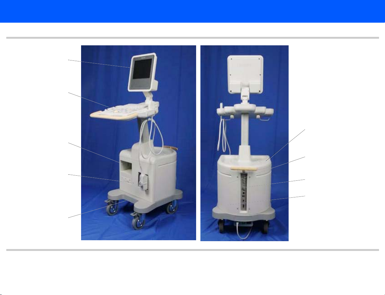
4535 612 34161 HD3 Service Manual Page 28
CSIP Level 1 General Information: System Overview
Figure 1-1 HD3 Ultrasound System
Video monitor
Control panel
System enclosures
B/W printer bay
Transducer
connectors
Cart
E-Box (internal)
I/O panel (rear)
Power supply
(internal)
Page 29

4535 612 34161 HD3 Service Manual Page 29
CSIP Level 1 General Information: System Overview
Applications
Modes
The following applications are available on the HD3 system. Refer to the HD3 Getting Started
manual for detailed feature information regarding these applications:
• Abdominal
• Small parts and superficial
• Pediatric
• Musculoskeletal
• Obstetrical
• Gynecological and fertility
• Prostate
• Vascular
• Cardiac Adult
The following imaging modes are available on the HD3 system. Refer to the HD3 Getting Started
manual for detailed feature information regarding these modes:
• 2D
• 3D
• M-mode
• Pulsed-wave (PW) spectral Doppler
• Color flow
• Color Power Angio (CPA) imaging
• Duplex mode and Simultaneous mode
Page 30

4535 612 34161 HD3 Service Manual Page 30
CSIP Level 1 General Information: System Overview
Tr an s d uc e r s
Languages
The system has two electronically-switched transducer connectors. The following five transducers are supported (also see Section 15, “Transducers”):
• C4-2
• C5-2
• C9-4ec
• C7-3
• L9-5
The system software supports the following languages at initial release:
• English
• French
• German
• Italian
• Spanish
Page 31

4535 612 34161 HD3 Service Manual Page 31
CSIP Level 1 General Information: System Overview
Options
The HD3 system software contains all of the available software options. The same software is
loaded into every system and because most of the system options are “software only” features,
each system can have whatever software options the customer purchases enabled at the factory
or, with the correct key-codes, on site. Purchased hardware options are shipped with the system.
The following options are available for this system at initial release:
Software Options
• Image Review
• DICOM networking
• Freehand 3D (shown on the system as an option, but is currently enabled in every system
shipped)
• Harmonic Imaging (shown on the system as an option, but is currently enabled in every system shipped)
• Color Flow
Peripheral Options
See “Peripherals” on page 32.
Page 32

4535 612 34161 HD3 Service Manual Page 32
CSIP Level 1 General Information: System Overview
Periphera ls
The HD3 system supports the following peripheral devices (these are optional unless noted as
standard):
• Sony UP-895MD black-and-white (B/W) analog printer (Figure 1-2)
• Sony UP-21MD color analog printer (Figure 1-2)
• Mitsubishi HS-MD3000UA (NTSC) or HS-MD3000EA (PAL) VCRs (Figure 1-2)
• CD-RW Drive (this is standard on all systems Figure 1-3)
• MOD (magneto-optical disc drive Figure 1-3)
• Foot switch (2-pedal)
• Report printers: At initial release, print drivers for the following report printers are included
in the system software, but these printers cannot be purchased from Philips. Print drivers
may be added to support additional report printers as they are released:
- HP DeskJet 880C
- HP DeskJet 895cxi
- HP DeskJet 6122
- HP LaserJet 1200
- HP DeskJet 5550
- HP Deskjet 5650
- HP DeskJet 6540
- HP DeskJet 6840
- HP Business Inkjet 1200
- HP Laserjet 1320
• USB Flash Drive (supported, but cannot be purchased from Philips)
Page 33

4535 612 34161 HD3 Service Manual Page 33
CSIP Level 1 General Information: System Overview
Figure 1-2 HD3 Ultrasound System Image Printers and VCR
UP-21MD Sony Color Printer
UP-895MD Sony Graphic Printer
(Black and White)
HS-MD3000UA/EA Mitsubishi Video Cassette Recorder
Page 34

4535 612 34161 HD3 Service Manual Page 34
CSIP Level 1 General Information: System Overview
Figure 1-3 HD3 Ultrasound System Data Media
USB MOD Drive
CD-RW Drive
Page 35

4535 612 34161 HD3 Service Manual Page 35
CSIP Level 1 General Information: System Overview
Figure 1-4 HD3 Ultrasound System Foot Switch
Page 36

4535 612 34161 HD3 Service Manual Page 36
CSIP Level 1 General Information: Physical Description
Physical Description
Cart
System Control Panel
The HD3 physical structure is made of fabricated sheet metal and molded plastic parts. The system (Figure 1-1) consists of a cart, a user interface (control panel), a visual display (video monitor), and the ultrasound electronic components. Other important physical components are the
power circuits, software and data storage devices, and the system input/output (I/O) connection
panel.
See Section 4, “Theory of Operation” for a functional description of these system components.
The cart is made up of a base and framework that provides a chassis on which all system components are installed and interconnected.
Swivel-casters at the four corners of the cart base provide system maneuverability and braking.
The front casters can be fixed straight and locked, or unlocked, by foot-operated wheel locks to
mobilize or immobilize the system as needed.
The control panel (Figure 1-5) is a replaceable, self-contained module.
Page 37

4535 612 34161 HD3 Service Manual Page 37
CSIP Level 1 General Information: Physical Description
Figure 1-5 HD3 Ultrasound System Control Panel
System Monitor
Ultrasound Components
The video monitor (Figure 1-1) is a non-interlace 26.4 cm (10.39-in) color TFT LCD display that
is mounted on a mechanism that allows tilt and swivel positioning of the display.
The physical components that comprise the primary ultrasound elements of the system are the
Transducer Connector Assembly and the E-box circuit boards. See Section 13, “Configuration”
for pictures and locations of these system components.
Page 38

4535 612 34161 HD3 Service Manual Page 38
CSIP Level 1 General Information: Physical Description
Transducer Connector Assembly
The Transducer Connector Assembly (TCA) has the transducer connectors (contained in metal
shielding) that interconnect to the E-box Front End board.
E-box
The E-box is a card cage that houses the ultrasound signal generation and echo acquisition circuits. The following ultrasound system electronic circuits are contained in the E-box:
• E-box Motherboard (backplane)
• Front End (FE) Assembly
• Beamformer (BF) Board
• Beamformer-to-Front End Connector (BFC) (physically and electronically connects BF and FE
boards)
• Digital Scan Converter (DSC) Board
• PCC Board (embedded computer)
System Power Components
Software and Data Storage Components
The system electronic power components are the Isolation Transformer, Power Supply, and the
Power I/O Assembly.
See Section 14, “Parts” for illustrations and locations of these system components.
The software and data storage components (Figure 1-3) are physically comprised of the hard disk
drive (HDD), CD-RW drive, and when installed, the optional magneto-optical disk (MOD) drive.
Page 39

4535 612 34161 HD3 Service Manual Page 39
CSIP Level 1 General Information: Device Safety Requirements and Regulatory Compliance
I/O Panel
Cables
Device Safety Requirements and Regulatory Compliance
The I/O Panel, which provides connections for external devices, is installed into the rear of the
cart framing (see Figure 11-5 for connection descriptions).
Physical cables provide system signal interconnect and power distribution. Refer to Section 11,
“Cabling”, for detailed cable information.
The HD3 Ultrasound System complies with the following requirements for the International
Electrotechnical Commission (IEC), the Canadian Standard Association (CSA), and the Underwriters Laboratories (UL).
• IEC60950/EN60950 for data processing equipment
• IEC 60601-1/EN 60601-1for medical equipment
• IEC 60601-1-1/EN 60601-1-1 for medical equipment
• CSA22.2 No. 601.1
• UL 2601-1
For information about applicable safety standards and specifications, see the HD3 Getting Started
manual shipped with the system.
Page 40

4535 612 34161 HD3 Service Manual Page 40
CSIP Level 1 General Information: Supplies and Accessories
Supplies and Accessories
Open Source Software License
Supplies and accessories are not available from Philips Ultrasound. The customer is directed to
order biopsy guides by contacting their Philips representative or an authorized distributor.
Transducer covers and other supplies and accessories can be ordered from CIVCO Medical
Instruments:
CIVCO Medical Instruments
102 First St. South
Kalona, IA 52247-9589
Phone: (800) 445-6741, Ex. 1 for Customer Service (USA)
+1 319-656-4447 (International)
Fax: (877) 329-2482 (USA)
+1 319-656-4451 (International)
E-mail: info@civcomedical.com
Internet: www.civco.com
The HD3 system uses an embedded computer featuring the Linux operating system, parts of
which are open source software. The following notification is included in the customer’s Operat-
ing Notes:
This Philips ultrasound system may contain “open source” software. According to the terms
of the General Public License, a recipient may request a copy of any GPL-licensed source
code modules present in the system, for the cost of shipping and handling. Please contact
your local customer service representative for additional information.
The “additional information” is that the customer is entitled to a copy of the operating system
software and that you can order it for them if they want it. The part number for the HD3 system
Open Source Software is 453561228511.
Page 41

4535 612 34161 HD3 Service Manual Page 41
CSIP Level 1 System Specifications: Introduction
2 System Specifications
Introduction
Physical Specifications
Electrical Specifications
This section summarizes the system specifications for the HD3 Ultrasound System. For transducer specifications, see Section 15, “Transducers”.
The physical dimensions and weight of the HD3 are as follows:
• Height:
- Lowest position: 1,280 mm (50.4 in)
- Highest position: 1,455 mm (57.3 in)
• Depth: With no peripherals: 798 mm (31.4 in)
• Width: With no peripherals: 505 mm (19.9 in)
• Weight: Less than 61.2 kg (135 lb.) including monitor, and without peripherals.
The electrical specifications of the HD3 are as follows:
• AC input: 90 to 264 Vac, 47 to 63 Hz
• Ground impedance: 100 mΩ maximum
• Load: 1,150 VA maximum.
• AC output (including PC): non-sinusoidal 120 VRMS, 350 VA maximum
Page 42

4535 612 34161 HD3 Service Manual Page 42
CSIP Level 1 System Specifications: Environmental Specifications
Environmental
Specifications
System PC Specifications
The environmental specifications for the HD3 system are as follows:
• Operational:
- Temperature range: 10°C to +40°C (+50°F to +104°F)
- Relative humidity: 15% to 95% non condensing
- VCR and printers temperature limit: 10°C to +40°C (+50°F to +104°F) at 80% RH
- Altitude: 697 hPa to 1013 hPa (0 to 10,000 feet) at 35°C (95°F)
• Storage:
- Temperature range: –20°C to +60°C (–4°F to +140°F)
- Relative humidity: 15% to 95%, non condensing
- Altitude: 572 hPa to 1013 hPa
Ta bl e 2 -1 lists the PCC hardware specifications.
Table 2-1 Embedded PC Hardware Specifications
Component Specification
OS Linux
Memory 128 Synchronous DRAM
Hard drive 80 GB
VGA 640x480
ROM 2 Mbit Flash BIOS
Network Interface 10/100 Mb/s Tx
Keyboard PS/2
Page 43

4535 612 34161 HD3 Service Manual Page 43
CSIP Level 1 System Specifications: Monitor Specifications
Table 2-1 Embedded PC Hardware Specifications (Continued)
Component Specification
Mouse PS/2
IDE port Enhanced IDE interface
Monitor Specifications
The monitor specifications are:
• Type: TFT LCD
• Size: 10.4 inch
• Pixel Pitch: 0.33mm x 0.33mm
• 640 x 480 VGA at 60 Hz
• Color Depth: 8-bit, 262,144 colors
• Power Consumption: Total 3.5 Watt
Page 44

4535 612 34161 HD3 Service Manual Page 44
CSIP Level 1 System Specifications: Image Formats
Image Formats
The following image storage formats are supported by each HD3 storage device (Tab le 2 - 2):
Table 2-2 Supported Image Formats
Device Format
BMP JPEG TIF DICOM
Hard DriveXXXX
Flash MemoryXXXX
CD R/W XXXX
MOD XXXX
Page 45

4535 612 34161 HD3 Service Manual Page 45
CSIP Level 1 Safety: Introduction
3Safety
Introduction
About Safety Information
General Operating Safety
This section summarizes the safety information for the HD3 Ultrasound System.
Please read this and related information before using or servicing a Philips ultrasound system. It applies to the ultrasound system, transducers, recording devices, and any
optional equipment.
This system is intended for use by, or by the order of, and under the supervision of a licensed
physician qualified to direct the use of the device.
In this manual, WARNIN G is used to indicate the presence of a hazard that can cause personal
injury, death, or substantial property damage if the warning is ignored.
In this manual, CAUTION is used to indicate the presence of a hazard that can cause equipment damage if the caution is ignored.
In this manual, NOTE is used when additional comment or explanation is required about instal-
lation, operation, or maintenance information that is important but not necessarily hazard-related.
Read the HD3 Getting Started for detailed safety and standards information for the HD3 Ultrasound System. This guide includes critical information about the intended uses of the HD3 system, patient and operator safety, and device standards. This is information that maintenance
personnel should be aware of.
Page 46

4535 612 34161 HD3 Service Manual Page 46
CSIP Level 1 Safety: Electrical Safety
Electrical Safety
WARN INGS • Do not connect the ultrasound system to the same circuit used for life-support devices.
This equipment has been verified by a recognized third-party testing agency as a Class I device
with Type BF and Type CF isolated patient-applied parts and Type B accessories. For maximum
safety observe these warnings:
• Shock hazards may exist if this system, including all externally mounted recording and monitoring devices, is not properly grounded. Protection against electrical shock is provided by
grounding the chassis with a three-wire cable and plug. The system must be plugged into a
grounded outlet. The grounding wire must not be removed or defeated.
• To avoid risks of electrical shock and fire hazards, inspect the system power cord and plug on
a regular basis. Ensure that they are not damaged in any way.
• Do not remove the protective covers on the system; hazardous voltages are present inside.
Cabinet panels must be in place while the system is in use. All internal adjustments and
replacements must be made by a qualified Philips Ultrasound field service engineer.
• Do not operate this system in the presence of flammable gases or anesthetics. Explosion can
result from electrical ignition.
• To avoid risk of electrical shock hazards, always disconnect the system from the wall outlet
before cleaning the system.
Page 47

4535 612 34161 HD3 Service Manual Page 47
CSIP Level 1 Safety: Electrical Safety
WARN INGS • To avoid risk of electrical shock hazards, always inspect transducers before use: Check the
face, housing, and cable before use. Do not use if the face is cracked, chipped, or torn; the
housing is damaged; or the cable is abraded.
• To avoid risk of electrical shock, do not use any transducer that has been immersed beyond
the specified cleaning or disinfection level.
• All patient-contact devices, such as transducers, pencil probes, and ECG leads must be
removed from the patient contact prior to application of a high-voltage defibrillation pulse.
• Connection of optional devices not supplied by Philips Ultrasound could result in electrical
shock. When such optional devices are connected to your ultrasound system, ensure that
the total system earth leakage current does not exceed 300 μA.
• Avoid placing the system in an environment that may produce electrostatic discharges (ESD)
that could affect the ultrasound system performance. (Electrostatic discharges can cause the
ECG heart rate display to increase by 10% to 15% for a few seconds after the discharge, even
though the ECG heart rate display returns to normal within a few seconds. See “About Elec-
trostatic Discharge” on page 51.)
• Avoid placing the system in an environment that may produce electromagnetic interference
(EMI) that could impact the diagnosis of a patient. (Only a physician can determine if an artifact caused by radiated interference has a negative impact on image quality and the subsequent diagnosis.) See “Avoiding EMI and RF” on page 48.
Page 48

4535 612 34161 HD3 Service Manual Page 48
CSIP Level 1 Safety: Electrical Safety
Avoiding EMI and RF
CAUTION Avoid placing the system in an environment that may produce electrostatic discharges (ESD) that
Although the system has been manufactured in compliance with existing EMI/EMC requirements,
use of this system in the presence of an electromagnetic field can cause momentary degradation
of the ultrasound image. If this occurs often, review the environment in which the system is
being used, to identify possible sources of radiated emissions. These emissions could be from
other electrical devices used within the same room or an adjacent room. Communication
devices such as cellular phones and pagers can cause these emissions. The existence of radio, TV,
or microwave transmission equipment located nearby can cause emissions. In cases where EMI is
causing disturbances, it may be necessary to relocate your system.
Electrosurgical units (ESUs) and other devices intentionally introduce radio frequency (RF) electromagnetic fields or currents into patients. Because imaging ultrasound frequencies are also in
the RF range, ultrasound transducer circuits are susceptible to RF interference. While an ESU is
in use, the noise generated can severely interfere with the black-and-white image and completely
obliterate the color image.
could damage the ultrasound system. (See “About Electrostatic Discharge” on page 51.)
Page 49

4535 612 34161 HD3 Service Manual Page 49
CSIP Level 1 Safety: Mechanical Safety
Mechanical Safety
WARN INGS. • Before moving the system, be sure to power it off, remove any loose equipment from the top
Although the system is designed to be mobile, remember that it is very heavy, and that you must
take precautions when moving it. The physical aspects of this system present a hazard that can
cause injury, property damage, or equipment damage if the following information is ignored:
of the system, disconnect the system power cord, and disconnect all external devices. Move
and secure external devices away from the system.
• Make sure the control top is locked, to prevent its up/down movement and unlock the caster
locks before moving the system. Push with the handle at the front of the cart. After the system is in position, engage the caster locks to immobilize the system.
• Be aware of the casters as well as the extremities of the system when moving it. The system
is heavy enough in any configuration that it can cause injury to you or others. Exercise additional caution when going up or down inclines.
• When attempting to overcome an obstacle, do not push the system with enough force to
cause it to tip over. Do not exceed 10 degrees of incline.
• Never park the system on an incline.
• For transport, make sure the control top is locked and secure the system so that it cannot
roll or tip. Engage the caster locks and use wheel chocks and restraining straps. Do not
attempt to hold the system in place manually. Never strap or secure the system at any point
on the control top or monitor.
Page 50

4535 612 34161 HD3 Service Manual Page 50
CSIP Level 1 Safety: General Equipment Protection
CAUTIONS • Ensure that the cables for all patient-applied parts are secure before moving the system. Use
the cable management system to ensure that transducer cables are protected from damage.
• Do not roll the system over transducer cables or power cables.
• If the system behaves abnormally after moving or transporting, contact Philips Ultrasound
Customer Service immediately. The components can withstand considerable shock, but
excessive shock can cause a system failure.
General
Follow these additional precautions to protect the system from damage:
Equipment
Protection
CAUTIONS • For optimal performance, the ultrasound system should be connected to a power circuit
dedicated solely for the ultrasound system.
• Verify system and peripheral power sources are appropriate before connecting to them.
• Avoid placing the system in an environment that may produce electrostatic discharges (ESD)
that could damage the ultrasound system. See “About Electrostatic Discharge” on page 51.
Page 51

4535 612 34161 HD3 Service Manual Page 51
CSIP Level 1 Safety: General Equipment Protection
CAUTIONS • Excessive bending or twisting of cables on patient-applied parts may cause failure or intermit-
tent operation of the system. Take care not to run over cables with the system, which may
damage them.
• In general, only the area of the transducer acoustic window is watertight. Except where
specified in specific transducer cleaning instructions, do not immerse the remainder of a
transducer in any liquid.
• Practice proper cleaning or sterilization of a patient-applied part to avoid damage.
• Do not submerge the cables of patient-applied parts in solution. The cables are not liquid-
tight beyond the applied part/cable or cable/connector interfaces.
• Do not use solvents such as thinner or benzine or abrasive cleaners on the system, transducers, video monitor, touch screen, or any printer.
About Electrostatic Discharge
Electrostatic discharge (ESD), commonly referred to as a static shock, is a naturally occurring
phenomenon. ESD is most prevalent during conditions of low humidity, which can be caused by
heating or air-conditioning. During low-humidity conditions, electrical charges naturally build up
on individuals and can create static shocks.
An ESD condition occurs when an individual with an electrical energy buildup comes in contact
with objects such as metal doorknobs, file cabinets, computer equipment, and even other individuals. The static shock or ESD is a discharge of the electrical energy buildup from a charged
individual to a lesser or non-charged individual or object.
The level of electrical energy discharged from a system user or patient to the ultrasound system
can be significant enough to cause damage to the system or transducers. The following precautions can help to reduce ESD: antistatic spray on carpets; antistatic spray on linoleum; antistatic
mats; or a ground wire connection between the system and the patient table or bed.
Page 52

4535 612 34161 HD3 Service Manual Page 52
CSIP Level 1 Safety: Symbols
ESD Safeguards
Follow these general ESD guidelines to minimize deterioration or destruction of ESD-sensitive
electronic components:
• Avoid working in carpeted areas.
• If you use a vacuum cleaner to clean the interior of any part of the system sensitive to static
electricity, take the necessary ESD precautions to avoid static buildup and discharge.
• Use a properly grounded wrist strap.
• Use a grounding mat for assembly work on sensitive areas.
Symbols
The International Electrotechnical Commission has established a set of symbols for medical electronic equipment that classify a connection or warn of potential hazards. The classifications and
symbols are shown below.
Symbols on the System
Isolated patient connection. (Type BF)
Isolated patient connection for applied parts in direct contact with
major vessels. (Type CF)
Identifies the On/Off button on the system control panel.
Page 53

4535 612 34161 HD3 Service Manual Page 53
CSIP Level 1 Safety: Symbols
On the system AC Mains power switch, “ I “ represents on and
“O” represents off.
This symbol identifies a safety note. Ensure you understand the
function of this control before using it. Refer to the appropriate
section of the system documentation for an explanation of the
control.
The patient-applied part provides a degree of protection from
electrical shock. This symbol indicates that the patient-applied part
is defibrillator-proof. The patient-applied part is suitable for all
patient applications including direct cardiac applications.
IPx-1
IPx-7
Identifies fuse location. For continued protection from fire or
shock, replace only with the same type and rating fuse.
Identifies equipotential ground.
Indicates that this device is protected against vertically falling water
drops.
Indicates that this device is protected against the effects of fluid
immersion. This degree of protection can apply to transducers and
the foot switch.
Page 54

4535 612 34161 HD3 Service Manual Page 54
CSIP Level 1 Safety: Symbols
The connector near this symbol receives alternating voltages.
AUX POWER
ISOLATE OUTPUT
This isolated output auxiliary power is provided for connection of
the Philips-approved remote accessories.
Indicates that interference may occur in the vicinity of equipment
marked with this symbol.
ESD (electrostatic discharge): The product is marked with this
symbol to warn the user not to touch exposed pins. Touching
exposed pins can cause electrostatic discharge, which can damage
the product.
This product consists of devices that may contain lead or mercury,
which must be recycled or disposed of in accordance with local,
state, or federal laws.
Indicates separate collection for electrical and electronic
equipment in compliance with the Waste Electrical and Electronic
Equipment (WEEE) Directive.
Do not throw away. Dispose of in accordance with local, state, or
federal laws.
Page 55

4535 612 34161 HD3 Service Manual Page 55
CSIP Level 1 Safety: Symbols
R
L
B/W
Right and left audio output.
Color composite video output.
Microphone input.
S-Video connection.
Black-and-white composite video output.
Ethernet connection.
Universal Serial Bus (USB) input/output port.
Foot switch connection.
ECG input.
Page 56

4535 612 34161 HD3 Service Manual Page 56
CSIP Level 1 Safety: Symbols
External VGA connection.
Print trigger.
Date of manufacture.
The following symbols are used inside the system:
Dangerous voltages: This symbol appears adjacent to high-voltage
terminals. It indicates the presence of voltages greater than 1,000
Vac (600 Vac in the United States).
Identifies the point where the safety system ground is fastened to
the chassis. Protective earth ground.
Page 57

4535 612 34161 HD3 Service Manual Page 57
CSIP Level 1 Safety: Symbols
The following symbols appear on the product packaging to indicate environmental considerations:
Symbols on the Product Packaging
Atmospheric pressure range of 700 to 1,060 hPa for transport and
storage.
Relative humidity range of 20% to 90% (noncondensing) for
transport and storage.
Ambient temperature range -20°C to +60°C (-4°F to +140°F)
(noncondensing) for transport and storage. (Does not apply to
media).
Page 58

4535 612 34161 HD3 Service Manual Page 58
CSIP Level 1 Theory of Operation: Introduction
4Theory of Operation
Introduction
System Architecture
Operating System
This section provides a functional overview of the HD3 Ultrasound System by breaking down
the system into functional elements and describing their relationships and basic principles of
operation.
The HD3 system architecture is made up of the following basic functional elements:
• Physical assemblies comprising the mobile cart and system components
• Electrical power functions
• Ultrasound signal generation and control functions
• Echo acquisition and control functions
• Signal and image data processing and analysis functions
• Image display and audio presentation functions
A Linux operating system (OS) provides an integrated range of resources: drivers and handlers
for storage, video, serial and parallel ports, and support of file system services and graphical user
interfaces. The OS is resident on the hard drive. The system software performs these tasks:
• Processes requests from the control panel
• Sets up beamforming parameters
• Processes acquired ultrasound echoes into digital visual representations for conversion into
analog signals
• Performs measurements and calculations on acquired data
• Stores acquired data (such as images and user-entered data) for subsequent retrieval
Page 59

4535 612 34161 HD3 Service Manual Page 59
CSIP Level 1 Theory of Operation: Functional Description
Functional Description
The HD3 system produces ultrasound images using transducers, digital beamforming, and Doppler processing. The central processing unit of the system is the PCC Board. The ultrasound
components comprise digital beamformer technology that combines with the operating system
to support the system functions.
The HD3 system stores the ultrasound images and patient data on the hard drive and can copy
that data to the removable media, such as magneto-optical drive (MOD) disks, CD-R and
CD-R/W disks, and USB flash memory sticks for off-system review. The system can send the
images to a black-and-white printer, color printer, or to a VCR. It also generates reports that can
be printed.
After operating power is applied, the major functional elements combine to produce ultrasound
images. The user interface allows system control and viewing of the results.
The overall system functional flow is power development and distribution, analog signal processing, beamforming, continuous-wave and color Doppler processing, scan conversion, digital signal
processing, and video and audio presentation.
The HD3 system ultrasound engine physically and functionally comprises five primary circuit
boards, the TCA (page 63), the FE (page 63), the BF (page 63), the DSC (page 63), and the PCC
(page 64). Most of the ultrasound signal processing, image processing, analysis, and display functions are performed by software using the native processing power of the embedded computer
of the PCC Board.
Figure 4-1 is a simplified block diagram of the HD3 system, showing the relationship between the
primary circuit boards and indicating the major functional tasks performed by each.
Page 60

4535 612 34161 HD3 Service Manual Page 60
CSIP Level 1 Theory of Operation: Functional Description
Figure 4-1 HD3 System Functional Block Diagram
Monitor
PSA
TCA
Transducers
PCC
FE
PCC
Booting
3D, Sonoview
LCD interface
VGA interface
IDE interface
LAN/Ethernet interface
MIC
USB
Audio direction separation
Display: CRT & LVDS LCD
25 MHz system clock
Front End
128 channel high voltage switching
32 channel TGC amplifier
32 channel to 16 channel folding and
reorder
Transducer ID
Board ID
Transducer connector assy connection
BF
32 Channel TX pulser
16 channel A/D conversion
Synthetic Aperture
Beam Steering
DSC
Processes all signals from the Beamformer
board
Blood velocity and direction calculation
Generates 2D, Spectral and Color displays
I and Q data
Color filtering and calculation
Scan conversion
Routes RGB to PCC board for display
Image save (to hard drive via PCC board
Dual mode
Beamformer
Digital Scan Converter
Page 61

4535 612 34161 HD3 Service Manual Page 61
CSIP Level 1 Theory of Operation: Functional Description
Physical Functions
System Power
The HD3 physical structure is made of fabricated sheet metal and molded plastic parts. The system consists of a cart, a user interface (control panel), a visual display (video monitor), and the
ultrasound electronic components. Other important physical components are the power circuts,
software and data storeage devices, and the system input/output (I/O) connection panel.
The location and identification of the physical parts of the system are described in the General
Information, Cabling , Configuration, and Parts sections of this document. The functional nature
of each is described in the following paragraphs.
System power development and distribution is provided by the installation site source voltage,
the system isolation transformer, power supply, backplane power bus, and power interconnect
cables.
System Power Supply
• Input Voltage: (auto sensing)
- 100-120 Vac ±10%
- 200-240 Vac ±10%
- 50/60 Hz
Page 62

4535 612 34161 HD3 Service Manual Page 62
CSIP Level 1 Theory of Operation: Functional Description
• Output Voltage:
- + 3.3 Vdc
- + 5 Vdc
- - 5 Vdc
- + 12 Vdc
- + 12 Vdc
- + 97 Vdc
- - 97 Vdc
- + HV (+ 20 to + 80 Vdc)
- - HV (- 20 to - 80 Vdc
The system power supply has these features:
• Fault Protection: The AC outputs are fault-protected from an overload condition (including
turn-on surges). The AC input may be cycled to restore power.
• Overcurrent Protection: All outputs have overcurrent protection to protect damage to the
power supply from overcurrent load or short circuit conditions. Latched AC outputs will be
reset once the input power is cycled. The latched DC output will be reset if the input power
is cycled.
Power Distribution
System power distribution diagrams are shown in Figure 11-2.
Page 63

4535 612 34161 HD3 Service Manual Page 63
CSIP Level 1 Theory of Operation: Functional Description
Tr an s d uc e r Connector Assembly (TCA)
Front End (FE) Board
Beamformer (BF)
Digital Scan Converter (DSC)
The Transducer Connector Assembly (TCA) is the transducer select module, providing the system interface for two transducers (see Section 15, “Transducer Information”). It works with the
FE Board for transducer detection and identification, engaging the appropriate number of relays
to accommodate transmitting and receiving pulses and echoes.
The Front End Board provides the physical and electrical interface to the TCA, the transducer
identification and enable function, and downloads operational parameters from the PCC, providing real-time control of the transmit, receive, and beamforming functions.
The Beamformer Board is responsible for generating and transmitting pulses for the transducer
elements. When the returning echoes come back into the system, they are sent in analog form
through the FE to the Beamformer (via the Beamformer Connector Board that bridges and
interconnects the FE and the BF boards) for processing, where they are filtered prior to being
converted into digital data. Once the data is digitized, specialized circuits perform the beam
forming and steering.
The signal processing functions of digital beamforming that determine the real image quality of
the system include dynamic apodization, multiplication, coefficient loading, variable sample clock
generation, and dynamic gain control.
The DSC Board is multi-functional, performing functions supported by separate circuit boards in
larger systems. The DSC performs the functions of a digital signal processor, digital scan converter and real time clock, and video manager.
• DSP functions:
- Receives all signals from BF board
- Calculates blood velocity and direction
Page 64

4535 612 34161 HD3 Service Manual Page 64
CSIP Level 1 Theory of Operation: Functional Description
- Generates the 2D image, spectral Doppler spectrum and audio, Color and Power Dop-
pler image, and transmits these signals to the DSC part of the board and the I/O panel
• DSC and RTC functions:
When the DSC circuits receive ultrasound digital data from the DSP circuits, they perform
2D scan conversion and then transmit the video signals to the video management circuits.
• Video management functions:
- From DSC output to Main Monitor
- Image Save (save image at HDD by PC)
- Color Keying (VGA data + image data)
- Post Mapping (control image curve)
- Dual Mode
- Edge Enhancement
PCC Board
The PCC Board is similar to the motherboard used in a personal computer. The PCC acts as a
central processing unit, performing further processing of the image data, including the generation
of the image display to the screen. The PCC also serves as the main controller of the other
boards and as the organizer of all of the image management functionality.
The PCC determines system functionality and coordinates the overall communication between
the user and the system, which includes storing and saving images. The PCC communicates continually with the hard drive for operating parameters and hosts the following functions:
• USB
• Battery
• VGA
Page 65

4535 612 34161 HD3 Service Manual Page 65
CSIP Level 1 Theory of Operation: Functional Description
• 25 MHz system clock
• COM port
• LCD Interface
• PCI Interface
• Non-interlace to VGA conversion
• Non-interlace to interlace conversion
• Doppler sound
E-box Backplane
Input/Output Panel
User Interface
The Backplane (Motherboard) is the physical and functional “backbone” of the ultrasound
engine. It is connected to the power supply, from which it receives DC operating voltages to distribute to the system components via a power bus and power cabling. The Backplane also provides control and signal interconnection between the system components via buses and signal
cabling. The FE, BF, DSC, and PCC boards are all plugged into connectors on the Backplane.
The I/O Panel at the rear of the system includes a circuit board that accomplishes the interconnection between system components and peripheral devices (see Figure 11-5 for connection
descriptions).
The user interface comprises the controls, indicators, and output devices of the system.
The control panel (in conjunction with the monitor displays) is the primary operating interface
with the ultrasound system. The footswitch, with freeze and display change functions, is an
extension of the control panel.
The control panel consists of TGC slide pot controls, trackball, additional system control knobs
and buttons, and a QWERTY keyboard. An internal interface PCB reads all of the control inputs,
determines the function that has been selected, and transmits that information to the PCC for
processing.
Page 66

4535 612 34161 HD3 Service Manual Page 66
CSIP Level 1 Theory of Operation: Functional Description
Hard Disk Drive (HDD)
CD-RW
Magneto-optical Disk (MOD) Drive
Flash Memory Stick
The HDD, housed inside the system enclosure and connected to the PCC by an EIDE cable, contains the Linux embedded operating system, ultasound application software, and COTS software.
The HDD stores AP&I data and ultrasound images.
The CD-RW drive, housed in the system enclosure and connected to the PCC by an EIDE cable,
is a removeable-media device used for image and report archiving and system upgrading.
The MOD drive, an external device that connects to the PCC via one of the I/O panel USB connectors, is a removeable-media device used for image and report archiving.
The flash memory stick, an external device that connects to the PCC via one of the I/O panel
USB connectors, is a removeable-media device used for image and report archiving.
Page 67

4535 612 34161 HD3 Service Manual Page 67
CSIP Level 1 Installation: Introduction
5 Installation
Introduction
Installation Checklist
This section contains pre-installation and installation information for an FSE-install of the HD3
Ultrasound System. FSE installation consists of a pre-installation site check, uncrating and
unpacking the system, physically installing the VCR or color printer if purchased, and verifying
that the system is configured properly. Read this section completely before starting the system
installation. The instructions in this section assume that the system language is set to English.
NOTE Some customers may be offerred the option to install their own system. Customers
electing to install their own system will be provided with an HD3 Ultrasound System
Installation User Guide, which starts with the assumption that all pre-installation actions
are complete, that the system and system accessories have been uncrated and
unpacked, and that the system does not have the DICOM option enabled.
Use the following checklist to review what steps are necessary for proper system installation and
to verify that you have performed them all.
Perform a pre-installation site check (page 68). . . . . . . . . . . . . . . . . . . . . . . . . . . . . . . . . . . . . . . ❏
Check physical access for delivery and installation (page 68). . . . . . . . . . . . . . . . . . . . . . . . . ❏
Perform electrical and environmental checks (page 69). . . . . . . . . . . . . . . . . . . . . . . . . . . . . ❏
If applicable, gather site network (DICOM) information (page 69). . . . . . . . . . . . . . . . . . . . ❏
Uncrate and unpack the system (page 70).. . . . . . . . . . . . . . . . . . . . . . . . . . . . . . . . . . . . . . . . . . ❏
Inspect the system (page 71). . . . . . . . . . . . . . . . . . . . . . . . . . . . . . . . . . . . . . . . . . . . . . . . . . . . . ❏
Assemble the system (page 72). . . . . . . . . . . . . . . . . . . . . . . . . . . . . . . . . . . . . . . . . . . . . . . . . . . ❏
Install the peripherals (page 72).. . . . . . . . . . . . . . . . . . . . . . . . . . . . . . . . . . . . . . . . . . . . ❏
Page 68

4535 612 34161 HD3 Service Manual Page 68
CSIP Level 1 Installation: Inspecting the Installation Site
Install the system power cord (page 72). . . . . . . . . . . . . . . . . . . . . . . . . . . . . . . . . . . . . . ❏
Start up and configure the system (page 72). . . . . . . . . . . . . . . . . . . . . . . . . . . . . . . . . . . . . . . . . ❏
Set or verify the institution name, user language, and time and date settings (page 73 through
page 75). . . . . . . . . . . . . . . . . . . . . . . . . . . . . . . . . . . . . . . . . . . . . . . . . . . . . . . . . . . . . . ❏
Verify system options (page 76). . . . . . . . . . . . . . . . . . . . . . . . . . . . . . . . . . . . . . . . . . . . . . . . ❏
Configure the DICOM/connectivity network, if required (page 77).. . . . . . . . . . . . . . . . . . ❏
Configure other system settings (optional) (page 87). . . . . . . . . . . . . . . . . . . . . . . . . . . . . ❏
Prepare the peripherals (page 87). . . . . . . . . . . . . . . . . . . . . . . . . . . . . . . . . . . . . . . . . . . . . ❏
Perform a system functional check (page 87). . . . . . . . . . . . . . . . . . . . . . . . . . . . . . . . . . . . . . . . ❏
Present the system (page 88).. . . . . . . . . . . . . . . . . . . . . . . . . . . . . . . . . . . . . . . . . . . . . . . . . . . . ❏
Inspecting the Installation Site
Checking Physical Access for Delivery and Installation
Conduct an inspection of the site prior to system installation to ensure a trouble-free installation
and to assist the customer in providing an environment that supports reliable performance of the
system.
Check that the installation site is physically acceptable as follows:
• With the customer, evaluate site access for delivery. Consider the availability of a loading
dock, elevators, ramps, and the width of passageways and doors.
• Verify that there is adequate space available for system uncrating and installation.
• At each location where the system will be operated, verify that there is enough space for the
system and any external peripherals.
• Check adjacent rooms for activity and types of equipment that might negatively affect the
ultrasound system.
Page 69

4535 612 34161 HD3 Service Manual Page 69
CSIP Level 1 Installation: Inspecting the Installation Site
Checking Electrical and Environmental Requirements
Gathering Site Network (DICOM) Information
Verify that the system is to be installed and operated in a room or rooms that meet the electrical
and environmental requirements given in Section 2, “System Specifications”.
If the system DICOM feature will be used, it will be necessary to have the following connectivity
information before entering the DICOM settings as described in “Configuring the DICOM Fea-
ture” on page 78.
NOTE If the system is to communicate over a network, the customer site network administra-
tor must be available to supply configuration data.
The customer or their contractor shall install network cabling. If in-wall cabling is used, it is the
customer’s responsibility to install the correct type of cable in accordance with all applicable
building and fire codes. It is also the customer’s responsibility to maintain the in-wall cabling for
the life of the system.
Determine and record the following network information for later DICOM configuration:
• Identify the system administrator (and backup person, if possible).
• Obtain the following information from the system administrator:
- A list of all equipment that is part of the image management network. Also include device
type, model number, and software version applicable to each piece of equipment.
- Logical diagram of the network showing topology, subnets, and so forth.
- Locations of equipment.
- Locations of all DICOM Connectivity LAN attachment points.
- Locations of power outlets and connector types.
Page 70

4535 612 34161 HD3 Service Manual Page 70
CSIP Level 1 Installation: Uncrating and Unpacking the System
- Locations of any dedicated analog phone lines.
- All necessary Internet Protocol (IP) addresses and subnet information.
- IP address, subnet mask, Port number, and DICOM AE Title for the HD3 system.
- IP Address, Port number, and AE Title for each DICOM server.
• Determine the type of network cabling installed.
• Identify OEM equipment installers and contact them regarding the installation.
• Check device compatibility prior to connecting new devices (such as, printers or archive
devices) to the network.
Uncrating and Unpacking the System
Inspecting the Crate
Inspect the shipping container and uncrate the system as described in the following sections.
Inspect the shipping crate before unpacking the system:
• Examine the shipping crate for damage. Look for evidence that the crate was opened.
• Verify that the Shockwatch and Tiltwatch indicators on the outside of the carton have not
been activated. If the indicators are red, report this fact to the carrier and to the Philips
Ultrasound traffic department. Be sure to check the system for damage when it is uncrated.
• Report any damage or missing inventory to the carrier and to the Philips Ultrasound traffic
department.
NOTE Before uncrating the system, ensure the area in front of the shipping crate ramp is clear
for at least 2.74 m (9 ft). (The ramp is the front side and is labeled “OPEN THIS
END.”)
Page 71

4535 612 34161 HD3 Service Manual Page 71
CSIP Level 1 Installation: Inspecting the System
Uncrating
Inspecting the System
WARN ING Dangerous voltages are present inside the system. Do not install the system power cord or con-
Uncrate the system by following the instructions in “Uncrating the HD3 Ultrasound System” on
page 90. (Instructions for re-crating the system for shipment are provided in Section 10, “Disas-
sembly”.)
After the system is uncrated (“Uncrating the HD3 Ultrasound System” on page 90), conduct the
following inspections. Report any damage or missing inventory to the carrier and to the
Philips Ultrasound traffic department.
nect it to AC line voltage until correct line voltage has been verified, a thorough inspection of the
system has been performed, and the system has been properly assembled.
➤ To inspect the system after uncrating
1. Inventory the shipment against the packing list.
2. Inspect the outside surfaces of the system, monitor, and peripherals for damage.
3. Unlatch and rotate the control panel to verify that proper left and right swivel and up/down
movement.
4. Verify that the system rolls and turns smoothly on its casters.
5. Verify that proper caster brake and swivel operation.
6. Remove the system covers.
7. Remove any loose packing material, dust, or debris from the interior of the system.
8. Verify that there is good continuity between the power supply and system ground.
Page 72

4535 612 34161 HD3 Service Manual Page 72
CSIP Level 1 Installation: Assembling the System
Assembling the System
Installing the Printers, VCR, and Footswitch
Installing the System Power Cord
Assemble the HD3 system by installing the following components.
If the system is ordered with a B/W printer, it will come installed from the factory in the B/W
printer bay (Figure 1-1) .
If the system comes with a color printer or VCR, you will need to install it on the adjustable universal peripheral mounting plate, which is installed on the cart from the factory. Follow the color
printer or VCR installation instructions (“To install the color printer” on page 105, or “To install
the VCR” on page 111).
If the system comes with a footswitch, you will need to connect it. Follow the footswitch installation instructions (“To install the foot switch” on page 119).
NOTE The peripherals come from the factory already configured with the Philips-recom-
mended settings (refer to “Peripheral Settings” on page 266).
After the system has been inspected and properly assembled, if the system power cord is not
already installed, install the system power cord by following the instructions in “To install the sys-
tem power cord” on page 121.
Powe ring On
and Configuring the
System
When physical installation is complete, it is necessary and important to verify that the system is
properly configured.
After the system has been inspected and properly assembled as instructed in this section, verify
that the green AC Mains power switch (Figure 11-6) is in the off position (“O” label on rocker
switch is pushed in) and then plug the system power cord into a proper AC outlet. Push the AC
Mains power switch to the on position (“I” label on rocker switch is pushed in) and then press,
Page 73

4535 612 34161 HD3 Service Manual Page 73
CSIP Level 1 Installation: Powering On and Configuring the System
for aproximately 3 seconds, the power On/Off button on the control panel to power on the system.
Basic initial configuration is addressed in the following sections. For detailed user information
and instructions for configuring and operating the system, refer to the HD3 Getting Started manual.
Ver i fy i n g t h e Local Settings
➤ To check or set the institution name
1. Press Setup (F10).
The Setup window opens (Figure 5-1).
2. In the Setup window, click Local.
Type in, verify, or change the name of the institution.
At this (or a later time) you can also specify whether or not the Caps Lock setting is to be on
or off at startup and whether or not to have the system automatically create a medical
record number for new patients. See “Configuring Other System Settings” on page 87.
Page 74

4535 612 34161 HD3 Service Manual Page 74
CSIP Level 1 Installation: Powering On and Configuring the System
Figure 5-1 Setup Window (System)
Page 75

4535 612 34161 HD3 Service Manual Page 75
CSIP Level 1 Installation: Powering On and Configuring the System
➤ To verify or set the system time and date
1. Press Setup (F10).
The Setup window opens (Figure 5-1).
2. In the Setup window, click Local.
3. In the Date and Time segments, select the desired date and time format.
4. In either the Date or Time segment, click Set.
The Date and Time setup window opens.
5. In the Date and Time setup window, click the up or down arrows to specify the current year,
month, day, hour, and minute.
6. Click OK.
7. Click Save.
➤ To change the user interface language
1. Press Setup (F10).
The Setup window opens (Figure 5-1).
2. In the Setup window, click Local.
3. In the Language segment, select the desired language.
The selected language will not take effect until the system is rebooted.
Page 76

4535 612 34161 HD3 Service Manual Page 76
CSIP Level 1 Installation: Powering On and Configuring the System
Ver i fy i n g t h e System Options
HD3 systems leave the factory with all available software options onboard. All purchased
options are activated, those that haven’t been purchased are not. Verify that the activated
options are those that the customer ordered. You must have the correct authorization code
(password) to activate system options in the field.
➤ To verify or activate system software options
1. Press Setup.
The Setup window opens (Figure 5-1).
2. Click the Option tab.
The Option setup window opens (Figure 5-2).
3. Option rows showing a checkmark and a Lock button, indicate that the option is active. Verify that these options correspond to those that the customer is entitled to according to the
sales order.
4. Option rows without a checkmark and having an Unlock button, are not yet activated
(option must be purchased to obtain an Unlock code from the factory). Perform the following to activate an option:
a. Click the corresponding Unlock button and enter the option code in the Unlock Code
dialog box that opens. It is necessary to have the System Key (based on the hard drive
identifier), from the top left corner of the Option window, when requesting option
authorization codes).
CAUTION If an incorrect password is entered and okayed, the available option becomes unavailable.
b. Click OK.
c. Click Save.
Page 77

4535 612 34161 HD3 Service Manual Page 77
CSIP Level 1 Installation: Powering On and Configuring the System
Figure 5-2 Setup Window (Option)
Page 78

4535 612 34161 HD3 Service Manual Page 78
CSIP Level 1 Installation: Powering On and Configuring the System
Configuring the DICOM Feature
If the system you are installing has the DICOM option, you or the customer will need to configure the system DICOM feature. Since configuring the system for DICOM operation requires
specific information from the customer network administrator (see “Gathering Site Network
(DICOM) Information” on page 69), Philips recommends that you work with the customer to
configure the DICOM feature with the specific values that need to be entered. At initial installation, refer the customer to the HD3 Getting Started manual, which has instructions for viewing,
setting, or changing DICOM information and gives a description of each field in the "Glossary."
The basic steps for initially configuring the system for DICOM communications over a network
are as follows:
1. Enter the system DICOM parameters:
- Enter the AE Title, Station Name, and Port number for the HD3 system (page 78).
- Enter the network settings for the HD3 system (page 80).
2. Identify the DICOM storage devices (servers) that the system will use (page 80).
3. Identify the DICOM printers that the system will use (page 80).
4. After the DICOM feature has been configured, you may want to test the communication
between the system and a server or a printer that was entered.(page 83).
5. Configure the DICOM Log file settings (page 83).
➤ To configure the system DICOM parameters
1. Press Setup.
The Setup window opens (Figure 5-1).
2. Click the DICOM tab.
The DICOM setup window opens (Figure 5-3).
Page 79

4535 612 34161 HD3 Service Manual Page 79
CSIP Level 1 Installation: Powering On and Configuring the System
3. Enter the AE Title, Station Name, and Port number for this HD3 system. You will need to
re-boot the system in order for the AE Title change to take effect.
Figure 5-3 Setup Window (DICOM)
Page 80

4535 612 34161 HD3 Service Manual Page 80
CSIP Level 1 Installation: Powering On and Configuring the System
4. Click System Network Settings.
The System Network Settings window opens (Figure 5-4).
5. View or enter the Network properties for this HD3 in the corresponding fields. If you enter
properties, click Apply when finished, otherwise click Close.
➤ To identify the DICOM storage devices that the system will use
1. Click Add in the DICOM setup window (Figure 5-3).
The Server Configuration window opens (Figure 5-5).
2. Select STORE from the Service menu.
3. Enter all of the parameters for the storage device.
4. Click OK.
5. Repeat step 1 through step 4 for each storage device the system will use.
NOTE You can configure multiple storage devices and printers, but the system will send only
to the storage device and the printer selected.
➤ To identify the DICOM printers that the system will use
1. Click Add in the DICOM setup window (Figure 5-3).
The Server Configuration window opens (Figure 5-5).
2. Select PRINT from the Service menu.
3. Enter all of the parameters for the printer.
4. Click OK.
5. Repeat step 1 through step 4 for each storage device the system will use.
Page 81

4535 612 34161 HD3 Service Manual Page 81
CSIP Level 1 Installation: Powering On and Configuring the System
Figure 5-4 System Network Settings Window (DICOM)
Page 82

4535 612 34161 HD3 Service Manual Page 82
CSIP Level 1 Installation: Powering On and Configuring the System
Figure 5-5 Server Configuration Window (DICOM)
Page 83

4535 612 34161 HD3 Service Manual Page 83
CSIP Level 1 Installation: Powering On and Configuring the System
➤ To test the communication between the system and a server or a printer
1. Press Setup.
The Setup window opens (Figure 5-1).
2. Click the DICOM tab.
The DICOM setup window opens (Figure 5-3).
3. Highlight the device that you want to test.
4. Click Test to initiate a DICOM verify (“ping”) test signal from the system to the device.
The test will produce a results message similar to one of the examples shown in Figure 5-6.
➤ To configure the DICOM Log file
NOTE The defaults for the DICOM logging parameters are reasonable for most circum-
stances. Do not change the settings unless you have a specific troubleshooting need.
1. Press Setup.
The Setup window opens (Figure 5-1).
2. Click the Admin tab.
The Admin setup window opens (Figure 5-7).
3. Click (DICOM Log) Open.
The DICOM Log window opens (Figure 5-8).
4. Enter the DICOM Log parameters and click Close.
5. Click Save on the the Admin tab.
Page 84

4535 612 34161 HD3 Service Manual Page 84
CSIP Level 1 Installation: Powering On and Configuring the System
Figure 5-6 DICOM Device Test Results Message Examples (DICOM)
=
=
=
Setup is correct
Physical connection problem or
wrong IP address
Wrong port number
Page 85

4535 612 34161 HD3 Service Manual Page 85
CSIP Level 1 Installation: Powering On and Configuring the System
Figure 5-7 Setup Window (Admin)
Page 86

4535 612 34161 HD3 Service Manual Page 86
CSIP Level 1 Installation: Powering On and Configuring the System
Figure 5-8 DICOM Log Window
Page 87

4535 612 34161 HD3 Service Manual Page 87
CSIP Level 1 Installation: Preparing the Peripherals
Configuring Other System Settings
Preparing the Peripherals
If appropriate for this installation, work with the customer and follow the respective instructions
in the HD3 Getting Started manual to initially configure the system settings not yet set to the customer’s preference. There are several categories of user setups:
• System
• Measure
• DICOM
• Option
• Peripherals
• Admin
➤ To configure other system settings
Refer to Section 6, “Customizing Your System,” in the HD3 Getting Started manual.
As applies, correctly load paper and ribbon in the printers and insert a tape cassette in the VCR.
Confirm that the system settings are appropriate for the installed peripherals.
NOTE HD3 peripherals are shipped and installed with their device settings set to the manufac-
turer’s default values. Printer and VCR device settings can be checked as described in
“Peripheral Settings” on page 266.
Checking System Functionality
Verify system functionality using the information in Section 6, “Performance Tests”. If system
testing reveals any problems, troubleshoot, repair, and retest the system before presenting it to
the customer for use.
Page 88

4535 612 34161 HD3 Service Manual Page 88
CSIP Level 1 Installation: Presenting the System
Presenting the System
When the system is ready, present it to the operators:
• Review the customer order with the customer to familiarize them with the system as purchased and its options.
• Review the “Read This First” section of the HD3 Getting Started manual with the customer.
Show them the important safety and operating information that it conatins and that it itemizes what user information has been provided for their system and peripherals.
• Review any Operating Notes with the customer.
• Show the operators how to turn the system and any external peripherals on and off. Explain
the importance of letting the system shut down completely before disconnecting the power
cord.
• Explain the importance of cycling the power at least once a week on systems that are left on
permanently.
• Instruct the customer how to back up and restore presets. Make a backup disk of the customer’s presets and configurations, and store it where service staff and the customer can find
it readily.
• Explain why it is important for them to never remove covers from the system because of
ESD and warranty considerations.
• Review with the customer, procedures for placing service calls or calling for technical
assistance.
Page 89

4535 612 34161 HD3 Service Manual Page 89
CSIP Level 1 Installation: Physical Installation Procedures
Physical Installation Procedures
Figure 5-1 Installation Procedure List
Uncrating the HD3
Ultrasound System
Monitor Support
Shipping Foam
Top-Mounted
Color Printer
Top-Mounted
VCR
MOD Drive
Foot Switch
System Power Cord
B/W Printer Plate
(No-Printer Systems)
NOTE The numbers in the installation illustrations correspond
to the steps in the installation procedure.
Page 90

4535 612 34161 HD3 Service Manual Page 90
NOTES
CSIP: Level 2 Installation: Physical Installation Procedures
Uncrating the HD3 Ultrasound System
Figure 5-2 Cutting the Poly Strapping Bands
Poly strapping bands
➤ To uncrate the HD3 Ultrasound
System
• Instructions for re-crating the system
for shipment are provided in Section,
“Disassembly (Removal) Proce-
dures”.
• Estimated time to uncrate the system is 10 minutes.
1. Remove (cut) the two poly strapping
bands from around the corrugated
container.
Page 91

4535 612 34161 HD3 Service Manual Page 91
CSIP: Level 2 Installation: Physical Installation Procedures
Figure 5-3 Removing the Corrugated Top Cover
2. Remove the top cover from the corrugated crate.
Page 92

4535 612 34161 HD3 Service Manual Page 92
CSIP: Level 2 Installation: Physical Installation Procedures
Figure 5-4 Removing the Corrugated Wrap
3. Remove the one-piece corrugated
wrap by lifting it straight up and over
the crate ramp.
Page 93

4535 612 34161 HD3 Service Manual Page 93
CSIP: Level 2 Installation: Physical Installation Procedures
Figure 5-5 Removing the Ramp Bolts
4. Remove the four bolts securing the
ramp to the pallet.
Page 94

4535 612 34161 HD3 Service Manual Page 94
CSIP: Level 2 Installation: Physical Installation Procedures
Figure 5-6 Placing the Ramp
56
5. Lift the ramp off the pallet.
6. Turn the ramp around and place the
ramp in front of the system with the
beveled edge facing up.
Page 95

4535 612 34161 HD3 Service Manual Page 95
CSIP: Level 2 Installation: Physical Installation Procedures
Figure 5-7 Removing the System Hold-down Brace
7. Remove the hold-down brace securing the rear of the system.
Page 96

4535 612 34161 HD3 Service Manual Page 96
CSIP: Level 2 Installation: Physical Installation Procedures
Figure 5-8 Removing the Wheel Chock
8. Remove the wheel chock from the
open (ramp side) of the crate.
Page 97

4535 612 34161 HD3 Service Manual Page 97
CSIP: Level 2 Installation: Physical Installation Procedures
Figure 5-9 Rotating the Rear Casters
9. Rotate the rear casters 180 degrees.
Page 98

4535 612 34161 HD3 Service Manual Page 98
CSIP: Level 2 Installation: Physical Installation Procedures
Figure 5-10 Rolling the System Off the Pallet
10. Ensure the ramp is properly aligned
in front of the crate.
11. Unlock the front casters.
12. Lift the antistatic bag and position
yourself on one side of the crate
toward the front of the ultrasound
system.
13. Grasp the control panel handle and
carefully guide the system down the
ramp and onto the floor.
Page 99

4535 612 34161 HD3 Service Manual Page 99
CSIP: Level 2 Installation: Physical Installation Procedures
Figure 5-11 Removing the Shipping Materials (Antistatic
Bag and Monitor Support)
Foam monitor support
14. Remove the antistatic bag.
15. Remove the foam monitor support
by sliding it toward the front of the
system and off the control panel.
16. Tilt the monitor up to its vertical
position.
Page 100

4535 612 34161 HD3 Service Manual Page 100
CSIP: Level 2 Installation: Physical Installation Procedures
Figure 5-12 Removing the Shipping Materials (Yoke
Support)
Foam monitor support
17. Engage the handle trigger and raise
the control panel to its highest point.
18. Remove the foam yoke support from
around the lift column.
19. Inspect the system as described in
“Inspecting the System” on page 71.
20. Dispose of the crate and packing
materials properly.
NOTE Do NOT return the crate or
packing materials to Philips.
Return to Installation Procedure List.
 Loading...