

Page 1
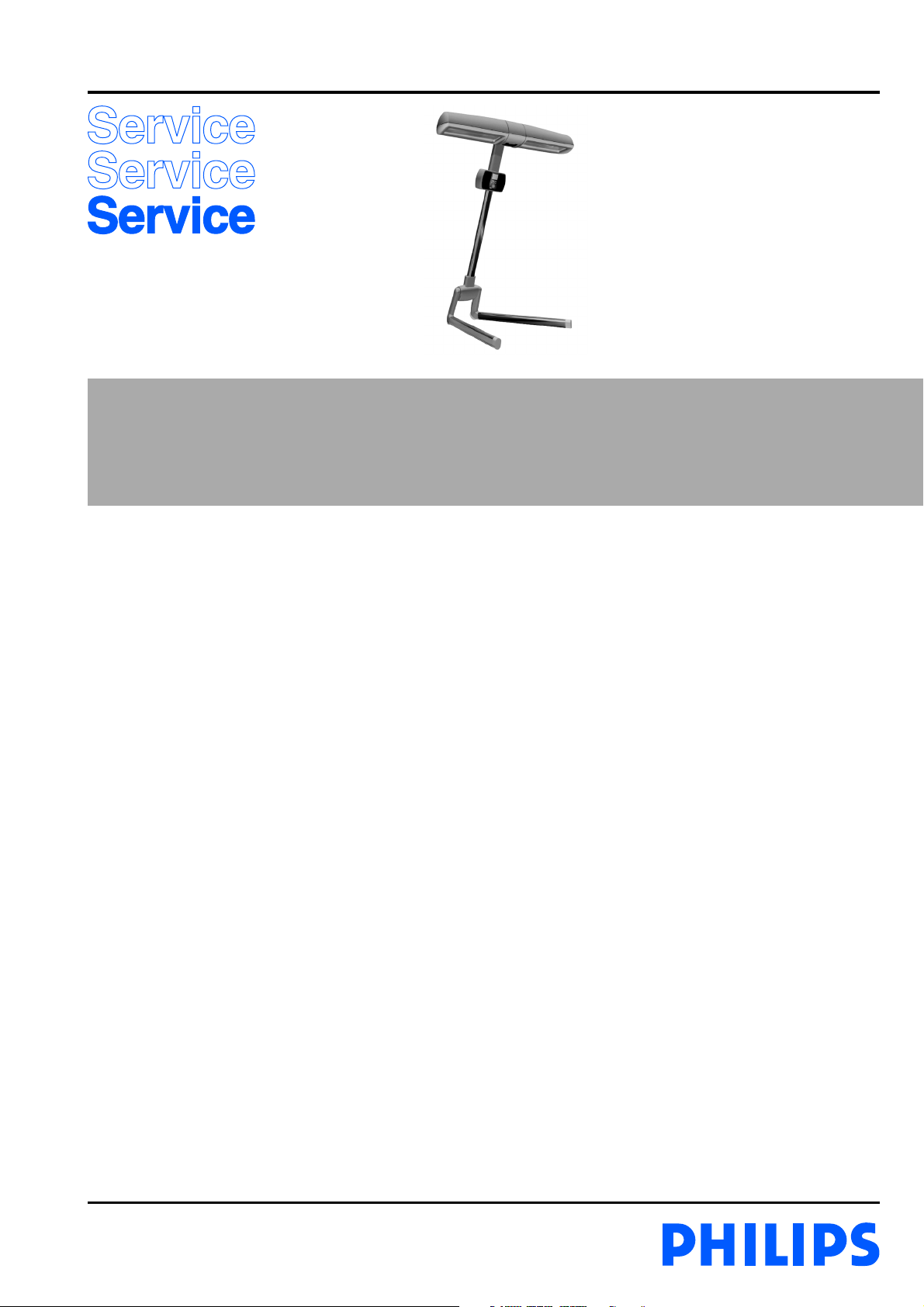
Sunstudio
HB935 /A
/B
/C
Philips Domestic Appliances and Personal Care
Service Manual
PRODUCT INFORMATION
Versions:
/A : Sensitive for error problems.
/B : With solution for ERROR in the display.
/C : With solution for ERROR in the display and/or
hum or bleep in the headphone.
- This full-body tanning appliance is equipped with an
electronic power supply. This means that when the
appliance is connected to the mains, the tanning or
relaxing functions are made visible by means of symbols
on the display. The set time is also shown on the display.
During the last minute of the set time, an accoustic
signal sounds.
- The UV lamps only burn in combination with the IR
(relax) lamps. When the UV lamps are on the IR lamps
burn at reduced intensity.
- The IR lamps can also be used separately at full intensity
for a relax session.
- This appliance is equipped with a sound module,
offering a selection of four nature sounds. The user can
also connect an external music appliance to play his/her
own music, either via the loudspeakers or the earphones.
- This tanning appliance has also been fitted with a scent
unit. The scent granules required for this unit can be
ordered as service part (see parts list).
IMPORTANT
- Because of the brief high starting voltage, the appliance
should be connected to a circuit protected with a 16A fuse.
- HPA lamps only go on at a restart if they have cooled down
sufficiently.
- Never touch the HPA lamps with your fingers. If necessary,
clean the lamps with a cloth moistened with some alcohol.
- When a new HPA lamp is installed, this lamp may have
a different colour compared to the other lamp. This is
normal and will disappear after a short period of use.
- After repair, the glass filters should be free from fingerprints.
If necessary clean the filters with some alcohol.
- Never look directly into the light of an HPA lamp when it
is on without protective goggles.
- Insufficient cooling – for instance when the vents are
blocked or when the fan has broken down – will cause the
thermal safety cut-out to switch the appliance off. Once the
cause of overheating has been removed and the appliance
has cooled down sufficiently, it will switch automatically on
again.
- Let the appliance cool down for 15 minutes before folding
it back into transport position and storing it.
- Only move the appliance when it is in transport position,
i.e. when it is folded.
- If there are complaints about inadequate tanning, the
output of the lamps can be measured with a UV-X 36
meter. For the minimum values, see table under ‘Technical
information’.
Published by Philips Domestic Appliances and Personal Care Printed in the Netherlands © Copyright reserved Subject to modification
04/11
Page 2
TECHNICAL INFORMATION
HB935/A /B /C
- Input voltage : 230 V – 50 Hz.
- Input consumption : Approx. 2200 W
- Fuse : 16 A
- UVA source : 2 x Philips Cleo HPA SYNERGIE
- IR source : 2 x Philips type 15040R
- Starter : KAIDA KCCD-G400
- Timer : 45 min. (Digital)
DISASSEMBLY & REPAIR INSTRUCTION
Always unplug the appliance before disassembly or repair!
1. Replacing lamps, fans and starters.
- Fold the appliance out into operating position.
- Remove 12 screws on the bottom of the lamp housing.
- Remove the upper part of the lamp housing
(the fans, starters and internal wiring are now accessible)
- Remove the screws of the mounting bridge.
- Remove the reflector clamps.
- Remove the reflector.
You have to lift the mounting bridge to do so.
2. Replacing lock grips, soundboard, relay board and power
SMPS (PCB)
- Remove the back of the timer housing.
- Now the lock grips, sound board, relay board and the power
SMPS are accessible
3. Replacing timer front with speakers and display
- Remove the grip main assy and slide the lamp housing
together with the slider off the column and place it on a table
or bed with the front pointing downwards.
- Remove the back of the timer housing.
- Remove the sound board, the relay board and the power
SMPS and undo the plug-in connections.
- Undo the 4 screws attaching the front to the black sleeve.
- Now the front can be removed.
4. Replacing seesaws (always replace both)
- Start disassembling the appliance as described under 3.
- Remove the back of the timer housing.
- Remove the 4 screws attaching the front to the black sleeve.
- Remove the black sleeve.
- Remove 2 shafts.
- Remove the spring. Be careful, for the spring is tensioned.
- Remove the seesaws.
- Radiation area : 190 x 70 cm
- Output (min) : 0.2 W/cm² at 65 cm. straight
UVX-36 meter below the distance indicator
- Protecting goggles : 2 x HB072
- Safety : Class II Cenelec UV type 3
- Weight : Approx. 19 kg.
To replace the hinge housing assy:
- Undo the screws of the main grip.
- Take the main grip off stand.
- Remove the black plastic tube from the column.
- Slide the lamp housing together with the slider off the
column.
To replace the paw and the paw cap (L&R) and the wheels:
- Undo the screw on the inside of the paw.
- Unsnap the paw caps.
- The wheels are now accessible.
- Undo 4 screws in the point of rotation of the paw to detach
the paw.
To replace the sliding plug leg:
- To replace the sliding plug of the leg, the existing sliding
plug has to be smashed with the pointed end of a hammer;
otherwise it can’t be removed without damaging the leg. A
new sliding plug can simply be snapped onto the leg.
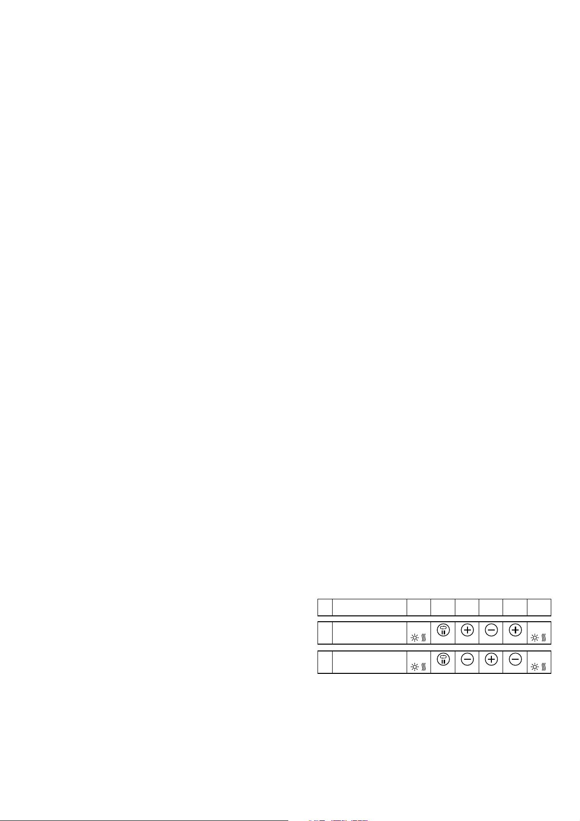
6. Resetting the timer and hour counter
- When the timer has detected a “temporary” fault, it shows
an error code on the display.
- If the error code does not disappear, there is probably a
defect in the relay board or the checking device in the
software.
- Reset the hour counter (e.g. after replacing the UV lamps).
01 234567
Resetting
1
the timer
Resetting
1
the hour counter
00 00
+ 1x + 2x+ 1x
Press
00 00
+ 2x + 1x+ 1x
Press
5. Stand
- The column of the stand has been mounted by means of
a hydraulic press and cannot be removed without causing
serious damage.
- As a result, the hinge housing cannot be disassembled either.
- The legs have been mounted on the paw by means of a
hydraulic press and cannot be removed without causing
serious damage.
2-12
Page 3
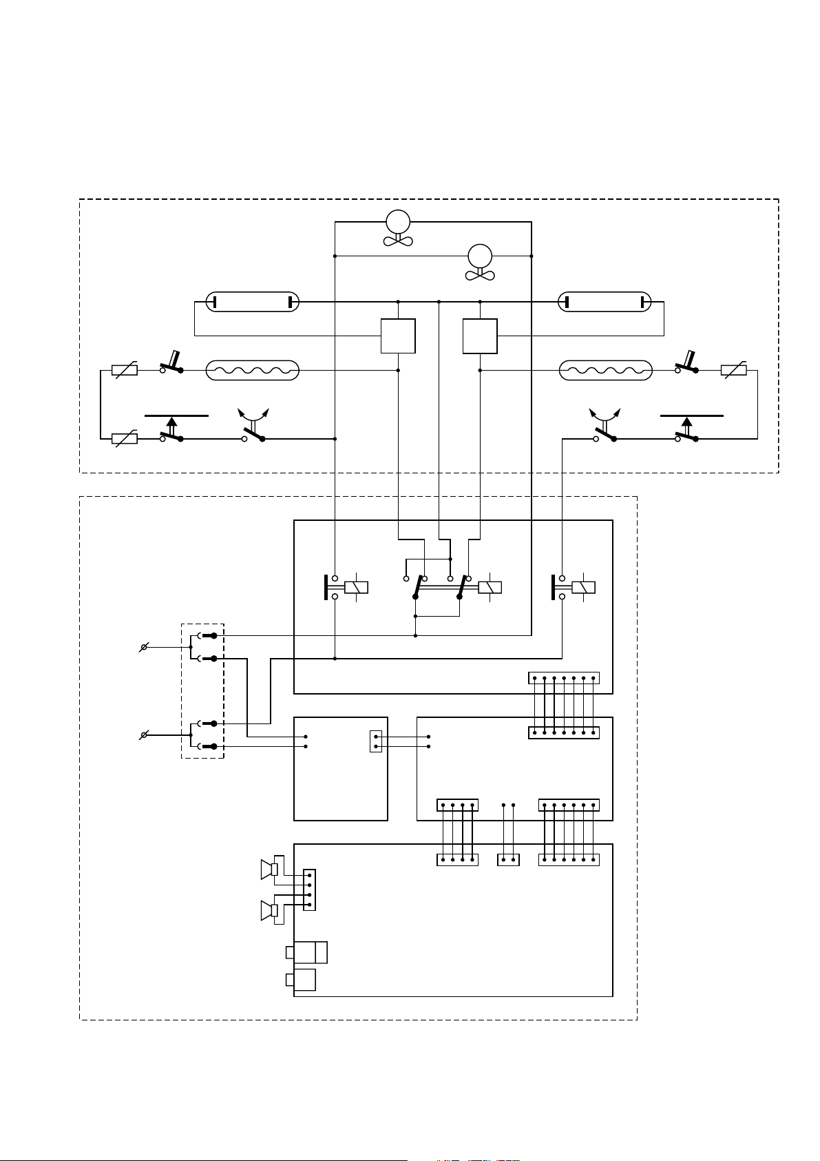
ELECTRICAL DIAGRAM Version /A
HB935/A /B /C
M1
M2
-t
NTC1
-t
NTC2
N
La2 La4
La1
TCO1 TCO2
SK3 SK5
TB1
SK4
Lp
N
S1
B
Relay Board PCB
S2
N
Lp
B
La3
SK6
J6
-t
NTC3
L
SMPS
(power)
LS1
J3
LS2
Headphones
Line-in
PCB
J5
Sound Board PCB
User Interface Panel
J4
J1 J2
3-12
Page 4
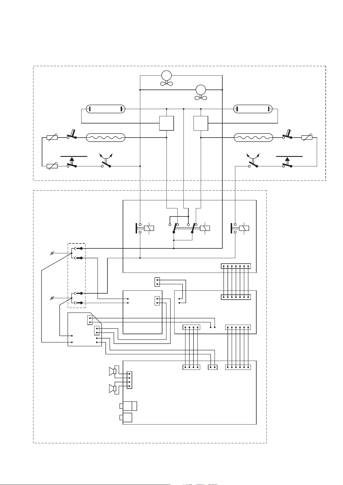
ELECTRICAL DIAGRAM Version /B and /C
HB935/A /B /C
M1
M2
-t
NTC1
-t
NTC2
N
La2 La4
La1
TCO1 TCO2
SK3 SK5
TB1
SK4
Lp
N
S1
B
Relay Board PCB
S2
N
Lp
B
La3
SK6
J6
-t
NTC3
Loose connector
L
UP
SMPS
SB
Error Fix PCB
LS1
LS2
Headphones
Line-in
SMPS
(power)
PCB
J3
J5
Sound Board PCB
User Interface Panel
J4
J1 J2
4-12
Page 5
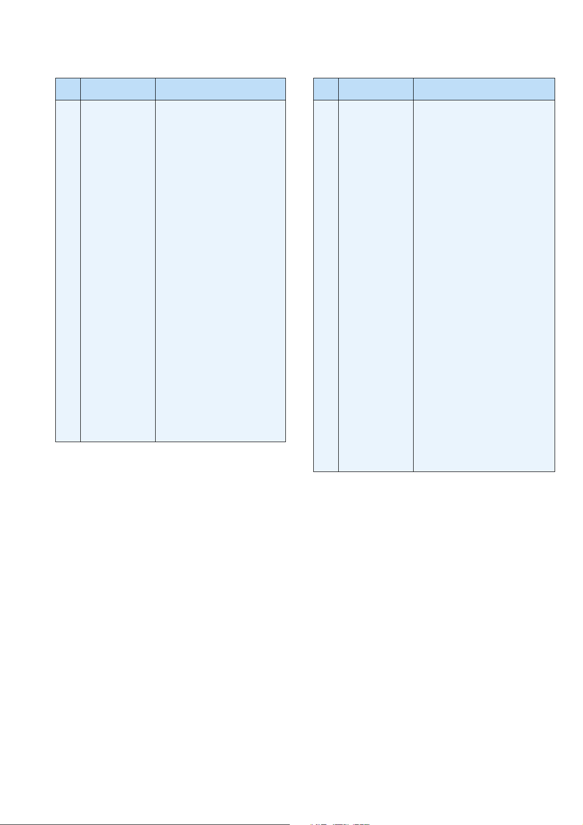
PARTS LIST
HB935/A /B /C
Item Service code Description
4222 062 95930
1
4222 062 95940
2
4222 062 95950
3
4222 062 95960
4
4222 062 95970
5
6
4222 062 96400
7
4222 062 95990
8
4222 062 96000
9
4222 062 96010
10
4222 062 96410
11
4222 062 96030
4222 062 96040
4222 062 96050
12
4222 062 96340
13
4222 062 96350
14
4222 062 96360
15
4222 062 96420
16
4222 062 96430
17
4222 062 96440
18
4222 062 96450
Grip main assy
Paw cap R
Leg assy R
Leg assy L
Leg sliding plug (set)
Hinge assy
Paw cap L
Wheel
Fan assy
Slider assy
Main fl ex EU
Main fl ex UK
Main fl ex CH
Sound Board PCB
Relay Board PCB
Timer housing front
Slider head top
Slider head cap
Slider head bottom
Hinge cap
Item Service code Description
4222 062 96390
24
4222 062 96190
25
4222 062 96460
26
4822 404 40639
27
4822 214 12272
28
29
4822 271 30619
30
4822 410 40417
31
4222 062 96230
32
4222 062 96240
33
4222 062 95020
34
4222 062 96250
35
4222 062 96260
36
4222 062 96270
37
4222 062 96280
38
4222 062 96290
39
4222 062 96300
40
4222 062 95920
41
4222 062 96310
42
4222 062 95250
43
4822 325 20102
Sleeve
Sea saw (set)
Lamp housing US
Switch bracket
Starter HPA
Micro switch
Switch pin
17 tabs PCB
Lamp housing LS
Distance indicator
Mid compartment
Scent cartridge
Compartment lid
Screw (set 3.5x20 and 3.5x12)
Lamp HPA
Lamp IR
Thermal cut off 90 °C
Lamp holder assy IR
Refl ector clamp
Lamp holder HPA
19
4222 062 96060
20
4222 062 96370
21
4222 062 96200
22
4822 265 30284
23
4222 062 96380
Lock grip assy R
Timer housing back
Lock grip assy L
Connecting block 3S
SMPS (power) PCB
44
4222 062 96320
45
4222 062 94580
46
4222 062 94570
47
4222 062 96330
4222 062 96481
48
4822 690 80147
49
4222 062 96490
Refl ector assy
NTC resistor 22W
NTC connector
Scent refi ll packages HB080
Scent refi ll packages “Only for EE”
Protecting Goggles HB072
Error Fix PCB
5-12
Page 6
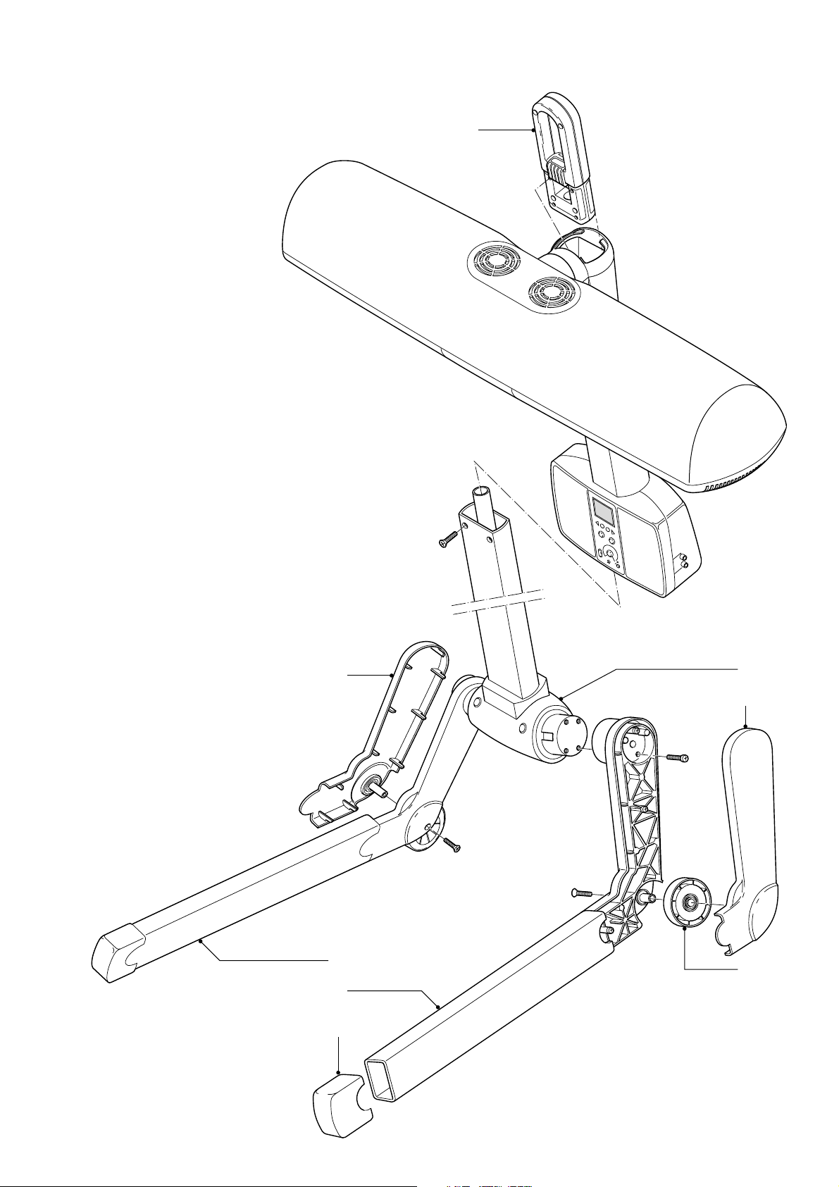
EXPLODED VIEW PART A
HB935/A /B /C
1
2
3
4
5
6
7
8
6-12
Page 7
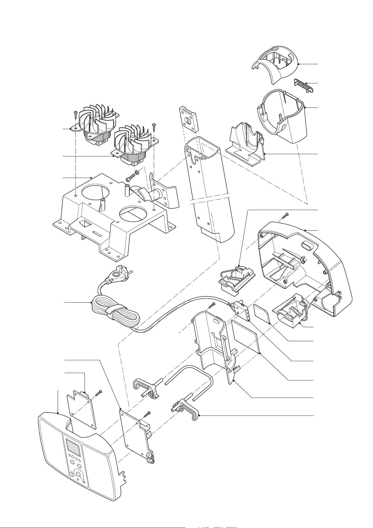
EXPLODED VIEW PART B
9
HB935/A /B /C
15
16
17
10
11
9
18
19
20
21
12
13
14
49 Verson
/B & /C
22
23
24
25
7-12
Page 8
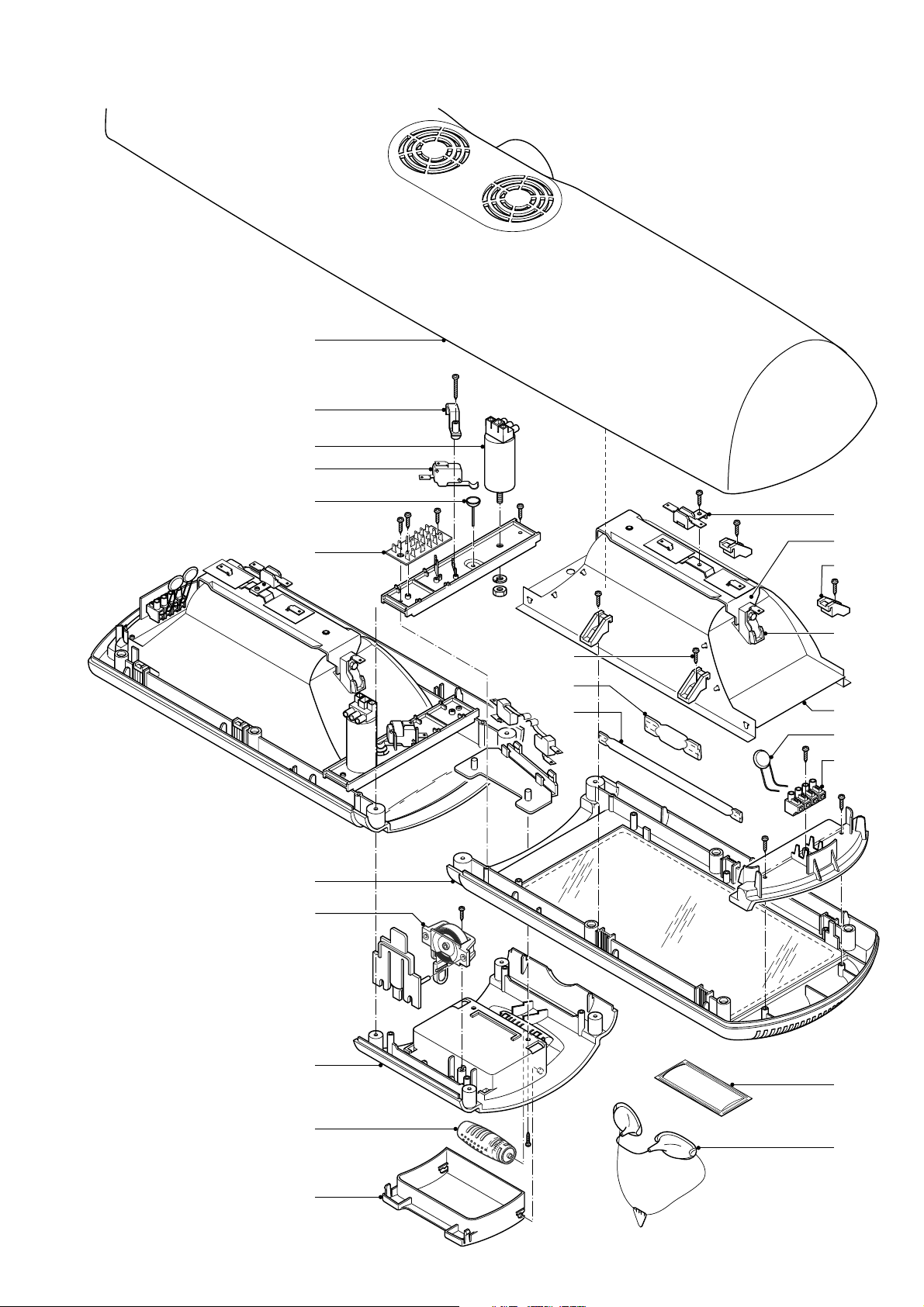
EXPLODED VIEW PART C
HB935/A /B /C
26
27
28
29
30
31
32
33
37
38
39
40
41
42
43
44
45
46
34
35
36
47
48
8-12
Page 9
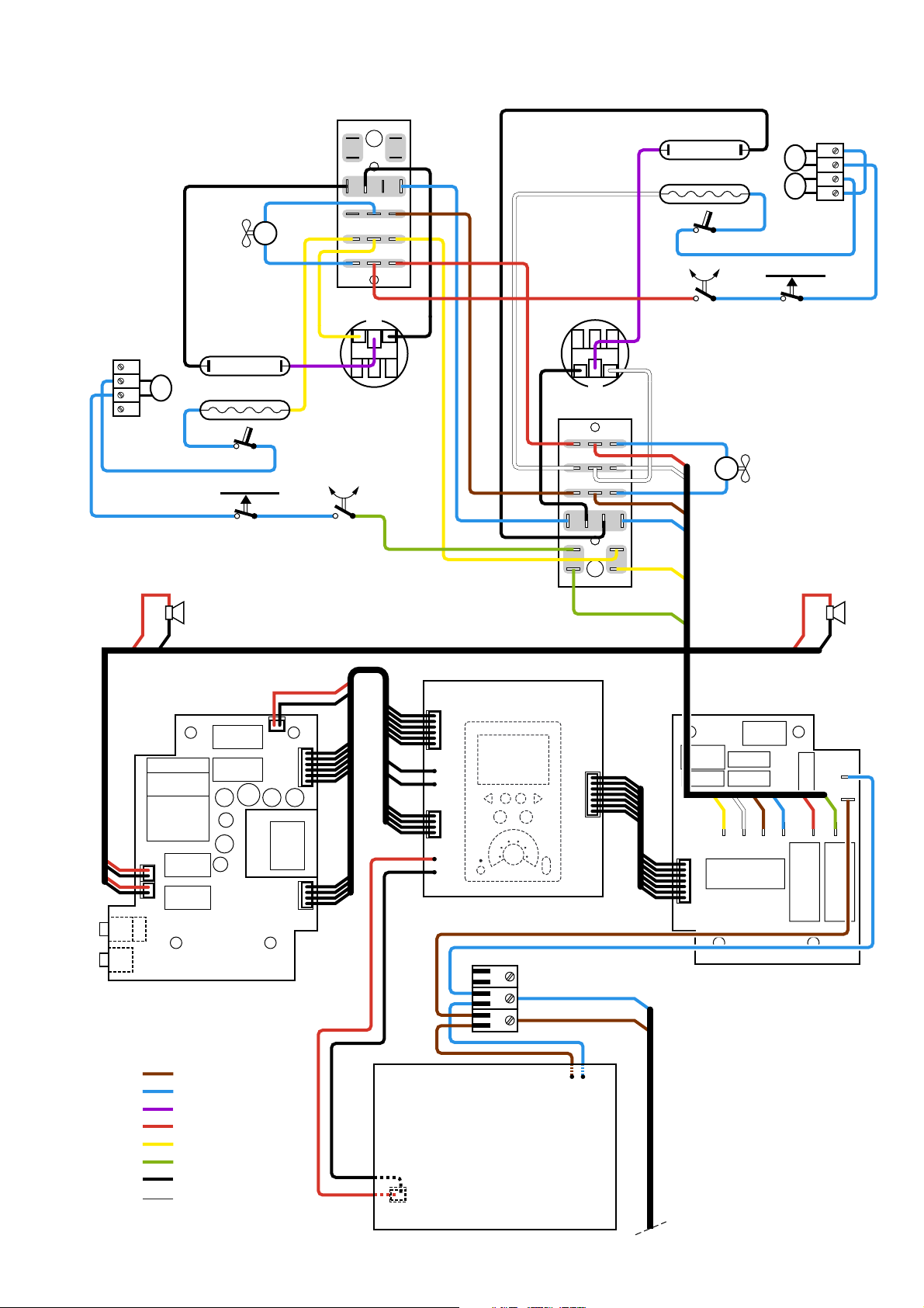
WIRING DIAGRAM Version /A
M2
PCB5
HB935/A /B /C
La2
La1
TCO1
NTC2
NTC1
TB2
TB3
NTC3
La4
La3
TCO2
SK3
Sound Board
J1
SK4
Lp
S2
S1
NB
User Interface Panel
NB
Lp
PCB4
SK2
M1
Relay Board
SK1
LS1LS2
J3
Headphones
Line-in
Brown
Blue
Purple
Red
Yellow
Green
Black
White
PCB2
J2
J6
J4
PCB3
TB1
N
L
SMPS
PCB1
J5
Mains
9-12
Page 10
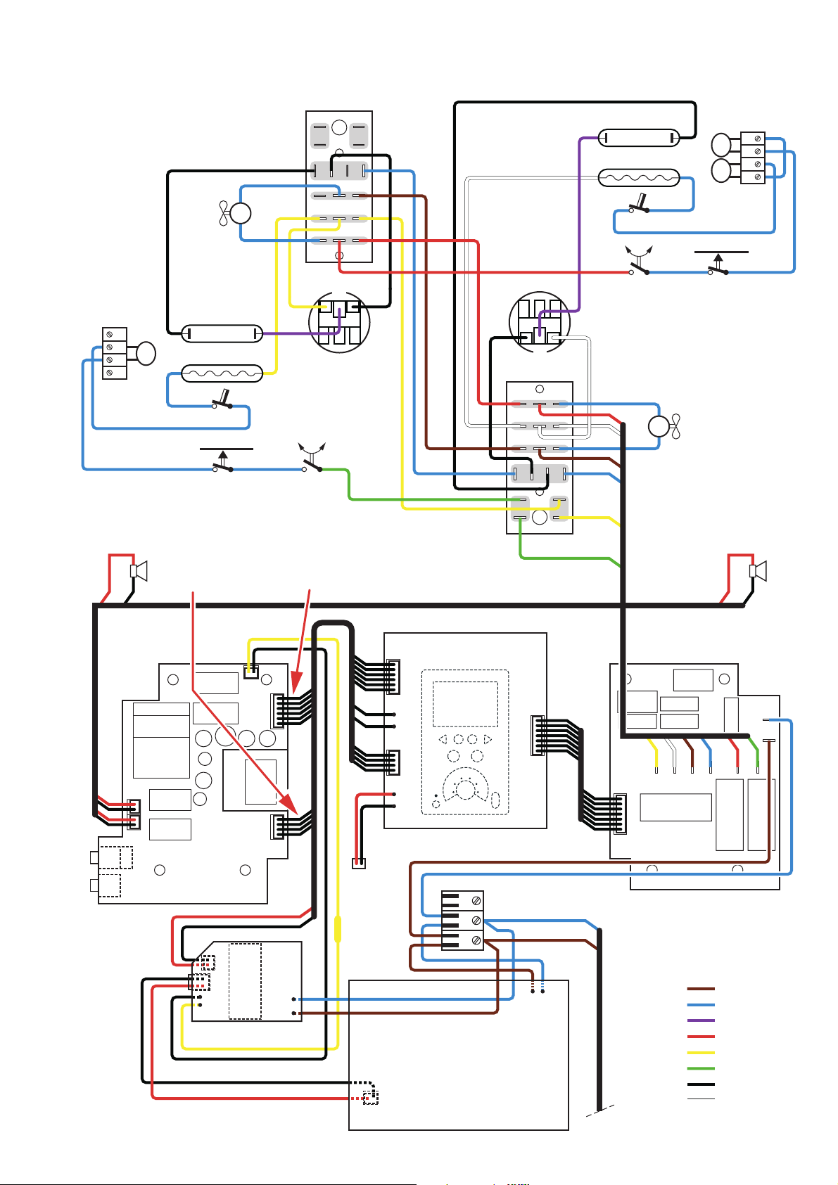
WIRING DIAGRAM Version /B and /C
PCB5
M2
HB935/A /B /C
La2
La1
TCO1
NTC2
NTC1
TB2
TB3
NTC3
Sound Board
Lp
La4
La3
TCO2
SK3
Remove two "ground loops" (Cut out these wires)
✂
Red
from this connection
J1
SK4
Remove the wires as far as possible
NB
S2
Yel lo w
from this connection
User Interface Panel
S1
NB
Lp
PCB4
SK2
M1
Relay Board
SK1
LS1LS2
J3
Headphones
Line-in
PCB2
Service PCB
J2
J4
Loose
connector
Resistor in
/C version
J5
TB1
N
L
SMPS
PCB1
J6
PCB3
Brown
Blue
Purple
Red
Yellow
Green
Black
White
Mains
10-12
Page 11
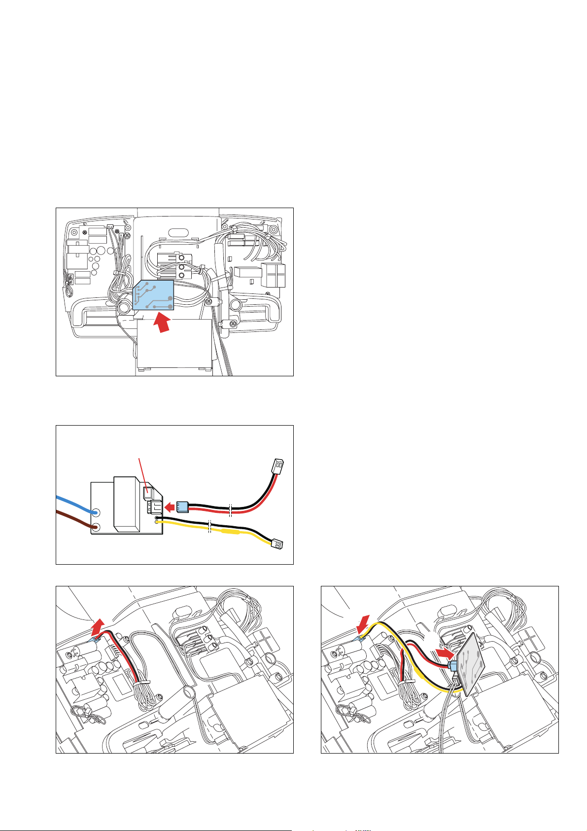
ERROR in the display and/or hum or bleep on the headphone
As a result of an intermitting contact, the text ERROR may appear on the display when the appliance is plugged in and switched on
(only occurs in HB935/A up to production code 0442).
This can be solved by assembling an extra PCB (item 49) according to the diagram shown on page 4 of the service manual and by
removing two “ground loops” according to de instructions on page 10.
Customers who have an HB935/B and complain about a hum or bleep: exchange the Error Fix PCB (item 49) fore one with a
resistance in the yellow wire and cut the “ground loops” according page 10.
If this gives problems because it does not fi t, you have to change item 14 complete!
After assemble the Error Fix PCB, always reset the timer.
Check if the PCB has been correctly assembled: the display turns black immediately after the plug is pulled out of the socket.
- Drawing to explain where the extra PCB should be
assembled.
HB935/A /B /C
Procedure after removal of the back of the timer housing:
"UP"
UP
SMPS
1
- Connect red/black wire to Error Fix PCB at “SMPS”.
3
2
- Disconnect red/black wire from the soundboard (1) and connect it to the Error Fix PCB at “UP” (2).
- Connect the yellow/black wire of the Error Fix PCB to the vacant connection of the sound PCB (3).
11-12
Page 12
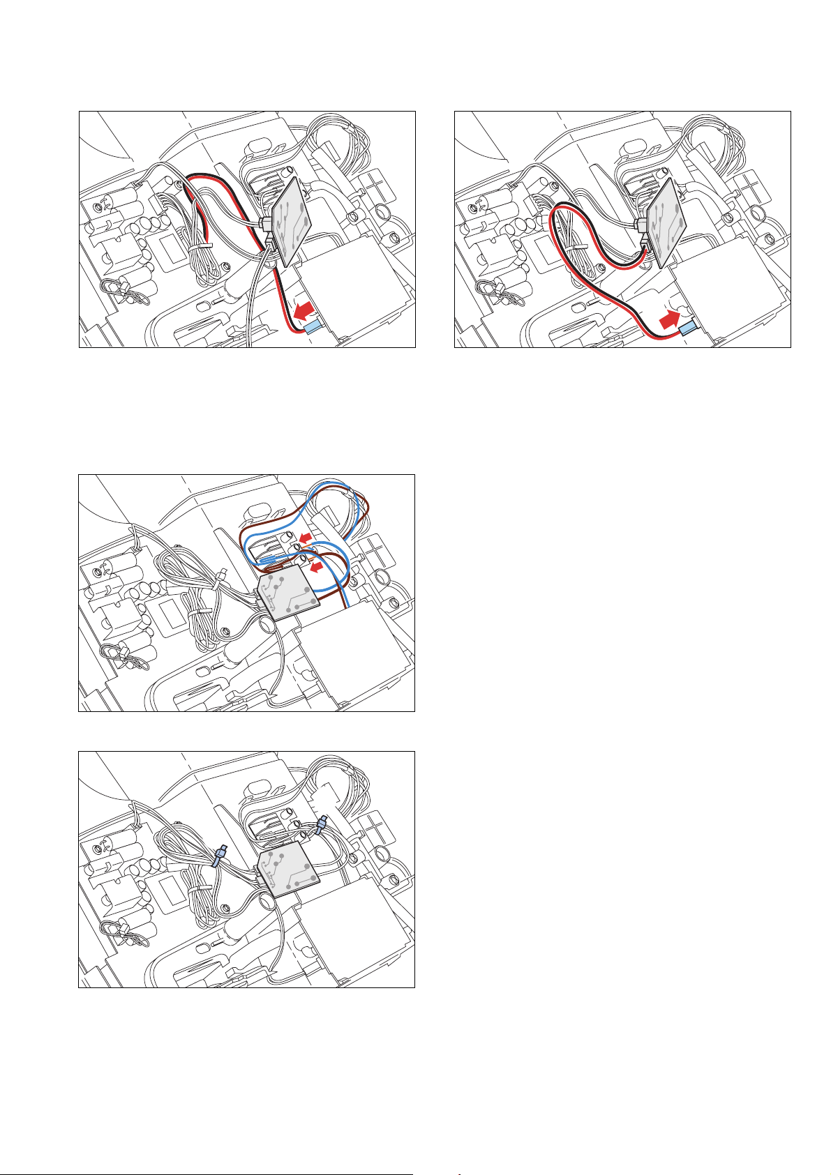
ERROR in the display and/or hum or bleep on the headphone
HB935/A /B /C
1
- Pull the plug with the red/black wire out of the power supply PCB (1) (this socket remains vacant and the wire should be fixed
in the bunch of wires).
- Plug the red/black wire of the Error Fix PCB into the power supply PCB (2).
- Put the red and blue wires across the connector block of the
mains cord, turn the Error Fix PCB upside down and fasten
it in the vacant spot with double-sided adhesive tape (first
remove the backing).
- Then connect the brown and blue wire of the Error Fix
PCB in parallel to the mains cord connector.
2
1
2
- Loop the wires and fasten them with the tie wrap
supplied (1).
- Tie the blue and brown wires to the mains cord with a tie
wrap (2).
12-12
 Loading...