

Page 1
HPA Solarium
HB828/A
Philips Domestic Appliances and Personal Care
Service Manual
PRODUCT INFORMATION
- On account of the short high starting current, the house
fuse should be of a 16 A-delayed type.
- The appliance will work in operating position only.
- Always check if the protecting glass pane (item 8) is
fitted after a repair.
- HPA lamps only start when they have cooled down
sufficiently.
- Never touch a HPA lamp with your fingers.
If necessary, clean the lamp with alcohol.
- Colour differences may occur when new lamps are
installed. This phenomenon is characteristic of HPA
lamps and disappears after a short period of use.
- After assembly the glass filter should be free from finger
prints and dust.
Clean the glass filter with alcohol, if necessary.
- Never look in the direction of the radiation part while
the lamps are on without wearing protecting goggles.
- In case of insufficient cooling (e.g. when the ventilation
apertures are blocked or when the fan is defective) the
safety device (item 9) will automatically switch off the
solarium.
Once the cause of overheating has been removed and the
solarium has cooled down sufficiently, a new session time
has to be set to switch the application on again.
- When the appliance is a few years old, we advise you to
apply a drop of thin oil to the bearings of the fan.
- Let the solarium cool down first (approx. 15 mins)
before closing and storing it away.
- Only move the solarium when folded.
- In case of complaints about little or no tanning, the output
can be measured by means of a so-called
UVX-36 meter.
The figure given on the title sheet is the minimum value to
be measured in the centre of the radiation field after 5 mins
of warming up and with the appliance connected to the
rated voltage.
TECHNICAL INFORMATION
- Input consumption : 1650 W / 230 V
- UV-A source : 3x HPA Flexpower 400-600
- Ballast : 3x BHA 500L / 230 V
- Starter : 3x SN 58-spec.
- Timer : 30 mins digital
- Radiation area : 185 x 75 cm
- Protecting goggles : HB072 - 4822 690 80147
2
- Output UVX-36 meter : min. 4.2 mW/cm
- Production code YYWW : on type plate
at 65 cm
Published by Philips Domestic Appliances and Personal Care Printed in the Netherlands © Copyright reserved Subject to modification
03/10
Page 2
RADIATION PART
HB828/A
FLOOR PART
DISASSEMBLY
- Remove the 10 screws with which the housing (item 7) is
fastened to the cover (item 1).
The housing will continue to cling to the cover.
- Disconnect the connectors of the connecting cable and
motor.
- Undo the other connections.
REPAIR INSTRUCTIONS
- It can be established whether lamps, ballasts or starters are
defective by interchanging them.
- When replacing a lamp holder (item 10) 2 tubular rivets
must be drilled out.
The bracket is fastened with 2 M2.5 x 10 bolts.
DISASSEMBLY
- Remove 6 square and 3 round ornamental props (item 20).
- Loosen 15 visible screws by which the cover (item 17) is
fastened.
- Pass the mains cord cover (item 30) and the flex holder
timer (item 16) through the opening below, after the screws
of that items have been taken out.
- Remove the cover (item 17) in horizontal position so that
the screws will not fall out.
(As screws with varying length are used, it is not possible to
interchange them.)
REPAIR INSTRUCTIONS
- The wheel can be replaced after the decorative cap has been
removed by means of a small screwdriver.
- A burned NTC resistor or overheated wiring points to a
wiring fault at the connecting block (item 20).
MISCELLANEOUS
- No specific issues.
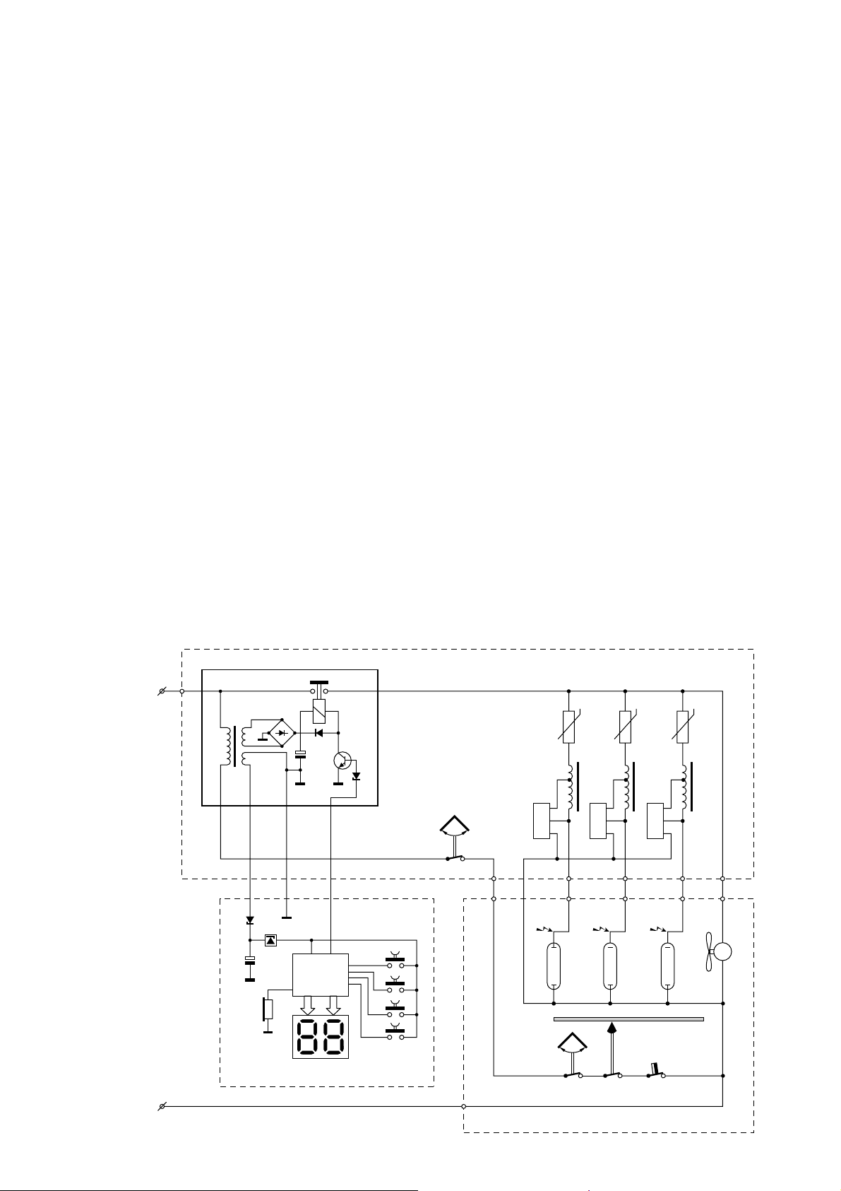
FLOOR PART
Buz
SK1
D
D
TS
C
D
SK2
µC
SK
NTC
S1
1
NTC
2
L1
S2
LA1 LA2 LA3
L2
NTC
3
S3
L3
M
POWER PCB
L
T
D
IC
C
REMOTE CONTROL UNIT
N
SK3 SK4 TCO
RADIATION PART
2-5
Page 3

PARTS LIST & EXPLODED VIEW RADIATION PART
1
2
LA1
HB828/A
TCO
9
LA2
3
4
5
6
SK3
SK4
LA3
10
14
11
7
12
13
8
Item Service code Description
1
4222 062 95730
2
4222 062 95620
3
4222 062 95020
4
4822 277 11375
5
4822 271 30619
6
4822 267 10902
7
4822 441 12207
Cover radiation part
Refl ector
Distance indicator
Ball switch
Micro switch
PCB connector
Housing radiation part
Item Service code Description
8
9
10
11
12
13
14
4822 466 62246
4822 252 20325
4822 325 20102
4222 062 95450
4822 134 30032
4822 492 90188
4222 062 95650
Glass pane white
Automatic cut out 100 °C
Lamp holder
Stand complete
HPA fl expower 400-600
Refl ector clamp
Motor with fan
3-5
Page 4

PARTS LIST & EXPLODED VIEW FLOOR PART
HB828/A
15
16
17
18
29
33
34
28
30
SK2
31
32
SK1
S1
S2
L1
S3
L2
L3
19
20
21
22
23
24
25
26
27
Item Service code Description
15
4222 062 95880
16
4222 062 95900
17
4222 062 95740
18
4222 062 95460
19
4822 462 11095
20
4222 062 94570
21
4222 062 94580
22
4822 441 12206
23
4822 146 10935
24
4822 124 40701
Remote control assy
Flex holder timer
Cover fl oor part
Lock knob
Set of props 6+3
Connecting block 8S
NTC resistor
Housing fl oor part
Ballast 500W/230V
Capacitor 25 µF/250V (CH only)
Item Service code Description
25
26
27
28
29
30
31
32
33
34
4822 219 80605
4822 265 20234
4822 528 11272
see item 5
4222 062 95810
4822 442 01449
4222 062 95030
4822 218 11844
4822 492 90187
4822 402 10789
Starter SN58 spec.
Connecting block 2S
Wheel
Mains fl ex EU
Mains cord cover
PCB with 2x6 tabs
PCB complete 230V
Flat spring
Lever
4-5
Page 5

WIRING DIAGRAM
HB828/A
M
YELLOW
La
3
WHITE
La
2
GREEN
La
1
(N) NL123
TCO
SK4
SK3
RED
BROWN
GREEN
WHITE
YELLOW
BLUE
SK2
RED
BLUE
N
L
BROWN
L
L
N
N
REMOTE CONTROL
BROWN
WHITE
GREEN
YELLOW
SK1
1
LLL
1
N
POWER PRINT
NTC3
GREY
NTC2
GREY
YELLOW
NTC1
GREY
BLUE
S3
L3
WHITE
S2
C1
BLUE
GREEN
S1
CH only
RED
YELLOW
RED
RED
WHITE
GREEN
BLUE
BROWN
BROWN
BROWN
L1
L2
5-5
 Loading...