

Philips HB578-A Service Manual
Domestic Appliances and Personal Care
Service
Service
Service
HB 578/A
SUNSTUDIO
COMBI
Solarium
GENERAL
The full-body tanner Sunstudio Combi HB 578/A is
equipped with a 30 minute timer.
After the pre-set tanning time, the appliance
automatically switches off.
The facial tanner (3 x PL 36W) can be switched on/off
by means of switch SK 1.
It has seven fans - two in the canopy and three in the
couch - for adequate cooling of the equipment during
operation and 2 fans for body cooling.
The voltage supply will only be switched on via the
relay (Re) after the timer has been set.
The starting current is limited by NTC resistors (NTC 1-9)
and phase-correction takes place by means of the
capacitors (C 1-9).
When choosing a place for the appliance, make sure
there is enough free space around the appliance to
guarantee proper cooling.
TECHNICAL DATA
Operating voltage : 230V, 50Hz
Power consumption : approx. 3050W
Ballast canopy : 12 x 100W
: 3 x 40W
Ballast couch : 12 x 100W
Starter type canopy : 12 x S12
: 3 x S10
Starter type couch : 12 x S12
Lamp type canopy 12 x Cleo Performance 100W
: 3 x PL 36W
Lamp type couch : 12 x Cleo Performance 100W
Timer : 30 min.
Safety class : double insulation
Test mark : CE
Length of mains cord : approx. 3m
Irradiation field : approx. 200 x 85 cm
Dimesions : approx. 208 x 101 x 91 cm
( L x W x H )
Published by Philips Domestic Appliances and Personal Care Printed in The Netherlands Copyright reserved Subject to modification
©
00/05
4322 277 00342
SAP coding HB 578
Service
Information
!
Service
Information
!
DISASSEMBLY
1
2
3
Canopy
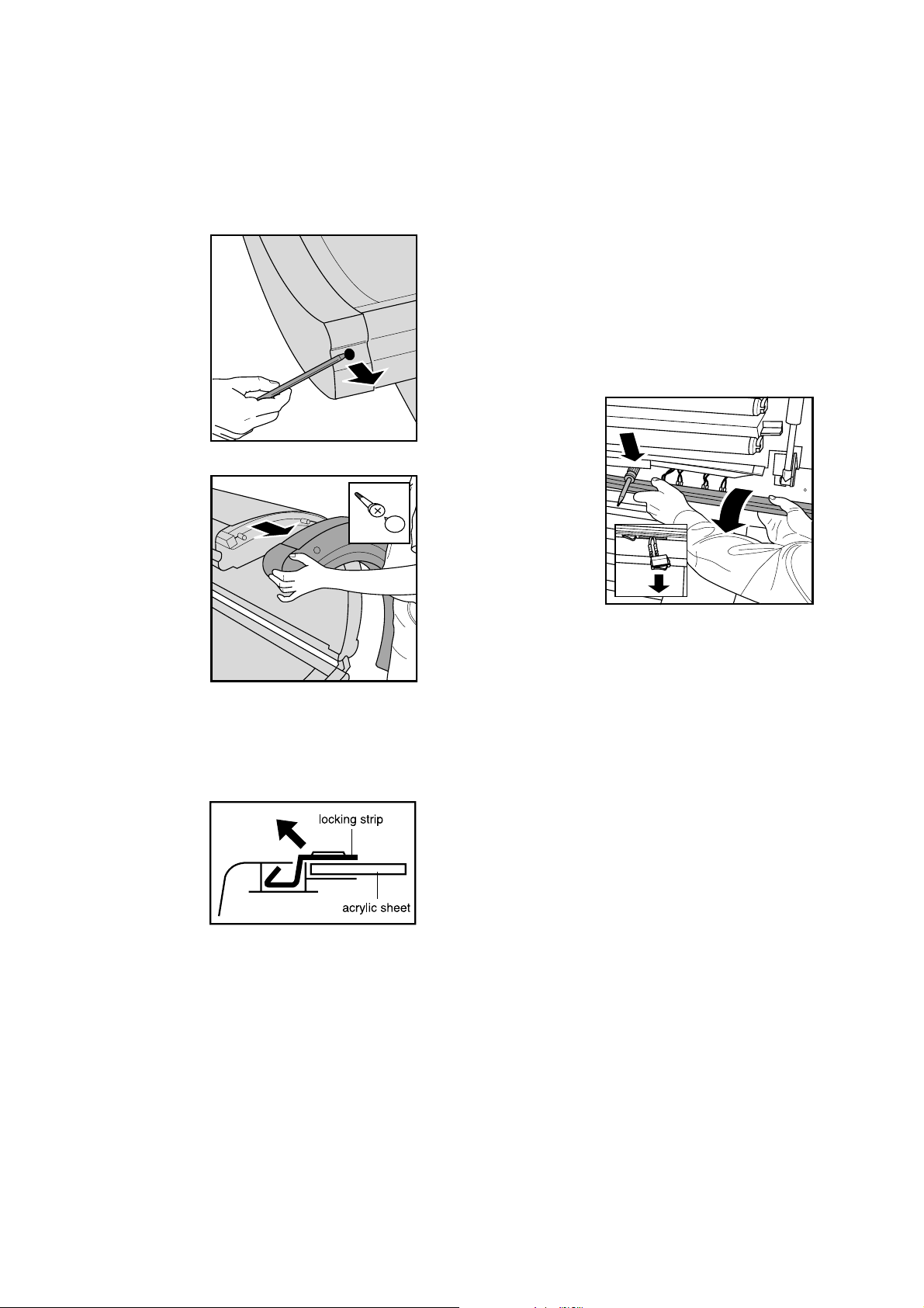
Use an appropriate knife to carefully remove the
two decorative caps that cover the plastic rivets
(7) from the end covers of the lamp housing (35 +
40) and then lever the rivets out of the lamp
housing with the knife.
Use an appropriate
screwdriver to
carefully remove
the 5 screw covers
(34) and to loosen
the screws (36).
Now all the other parts of the lamp housing of the
canopy are accessible and can be disassembled.
To disassemble the two upper fans (23), first
remove the two ballasts and then lift the fans with
the fan holders out of the housing so that the
fixing screws can be loosened.
Mark the position of the filter holders before
disassembly to make sure that they can be
assembled in exactly the same position when
reassembling the lamp housing, which is
necessary to ensure that the rivets of the cover of
the lamp housing (28) can be reinserted without a
problem.
To disassemble switches SK 1-3 (52, 54), the
housing part (43) must be pushed inwards and
downwards and kept apart with a suitable object.
The housing part (43) is highly flexible.
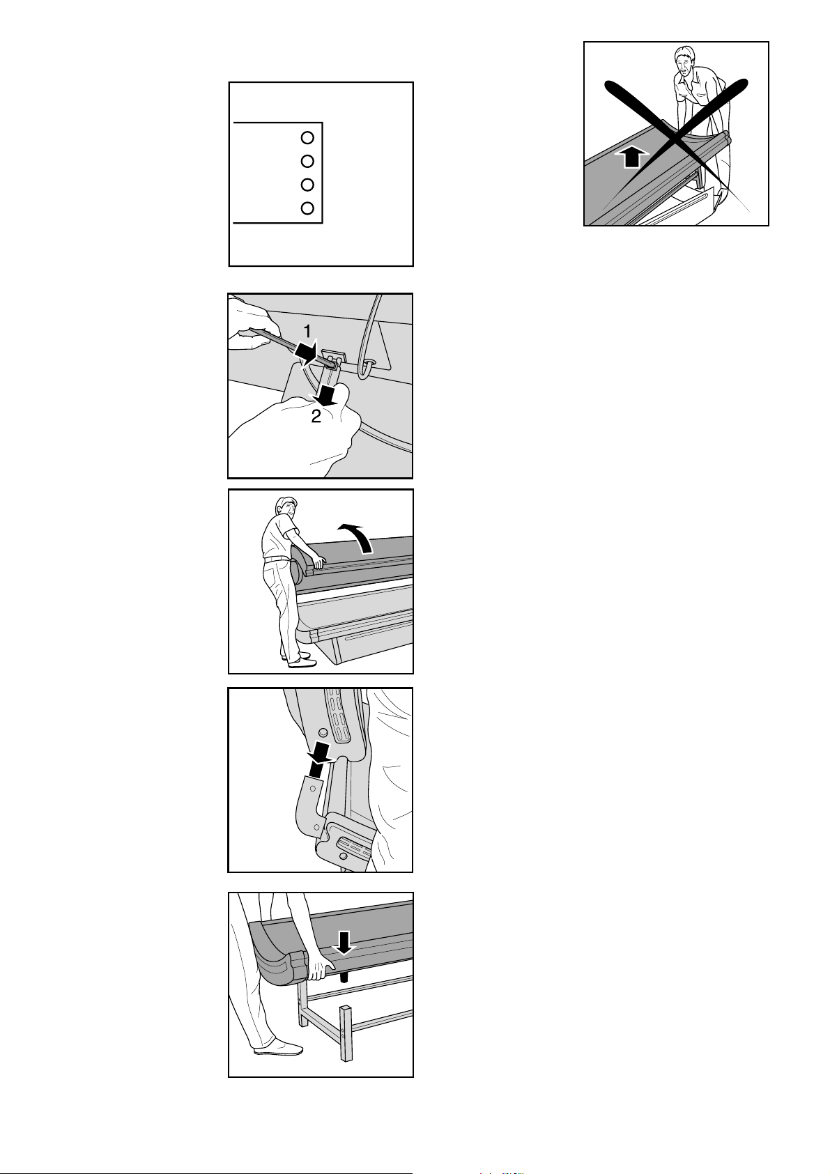
Appliances from
the first series
have another rivet
in their housing
part (43) that must
be removed before
the housing can be
pushed down.
This rivet must not
be replaced.
Now the end
covers can be
removed from the
lamp housing.
Unscrew the body cooling fan on the left side of
the canopy and take it out.
Remove the screws.
Pull the ornamental/retaining strips (3) of the
acrylic sheet (45)
up and snap them
out.
Lift the acrylic sheet from the appliance together
with a second person.
The TLs (42 + 53) are now accessible.
To remove the cover of the lamp housing (38), first
remove the decorative caps of the four plastic
rivets (37) with a suitable knife.
Be careful: prevent scratches on the cover!
Then pull the cover of the lamp housing out of the
grooves of the housing parts (39 + 43).
Lift the cover off the housing parts together with a
second person and place it on a soft surface
behind the appliance in such a way that the connecting cable (44) is not subjected to a too high
mechanical load.
To disassemble the gas pressure springs (50), fold
the canopy up and have a second person lock it in
this position.
Push housing part (43) inwards and downwards
and keep it apart with a suitable object.
Remove the spring retainer cover (51) with a
suitable screwdriver and then loosen the retaining
nut.
The gas pressure spring can now be removed
from the appliance.
Always use a new spring retainer cover (51) when
reassembling the appliance!
To disassemble the body cooling fans (61), take
the two housing halves (60 + 63) apart after
loosening four screws.
The fans that have already been unscrewed can
now be disassembled further.
Couch
Use an appropriate knife to carefully remove the
two decorative caps that cover the plastic rivets
(7) from the end covers of the lamp housing (6 +
13). Then lever the rivets out of the lamp housing
with the knife.
Use an appropriate screwdriver to carefully remove the 4 screw covers (34) and to loosen the
screws (36).
Now the end covers can be removed from the
lamp housing (6 + 13).
Pull the ornamental/retaining strips (3) of the acrylic sheet (9) up and snap them out.
Lift the acrylic sheet off the couch to gain access
GL
BR
WT
GN
YELLOW
BROWN
WHITE
GREEN
to the TLs (2), the starters (19) and the PCB (5).
To replace the
remote control
(30), unsolder connecting cable (29)
from the remote
control PCB.
To disassemble
the cover (15) of
the lamp housing,
pull the connecting
cable (44) of the
canopy out of the
socket in the
couch.
Loosen the screws located in the cover of the
lamp housing next to the studs (69).
Pull the cover out of the grooves of the housing
part (14) and lift it together with a second person
off the rest of the housing and put it on a soft
surface.
Now all the other parts of the lamp housing of the
couch are accessible and can be disassembled.
ASSEMBLY
Canopy
Lift the canopy off
the couch together
with a second
person.
Place the canopy
on a soft surface.
When assembling the acrylic sheet (45), make
sure the ornamental/retaining strips (3) have been
snapped in properly.
Always use a new spring retainer (51) when
reassembling the gas pressure springs (50)!
When assembling the housing part (43), make
sure the housing part has been properly snapped
in behind the metal strip.
Couch
When assembling the acrylic sheet (9), make sure
the ornamental/retaining strips (3) have been
snapped in properly.
When assembling the cover of the lamp housing
(15), please make sure that the small housing
cover (10) permitting entry of the mains cable,
remote control cable and other connectors laps
properly over the cover of the housing.
SERVICE TIPS
Then lift the couch
off its frame
together with a
second person and
place the couch on
a soft surface with
the lamps pointing
downwards.
• If a fuse blows when you switch on the
appliance, this is usually caused by a fuse that
acts too quickly.
In such a case, use of a slow 16A safety fuse is
recommended on account of the high starting
current.
• The fuse may also be activated as a result of a
defective NTC resistor, a defective capacitor, a
defective ballast or an overloaded circuit.
• If one or more TL’s have broken down, you can
track down the failure cause by exchanging
parts (ballasts, starters, lamps).
If these parts are OK, the wiring must be
checked, especially the connections to the lamp
holders.
• An unusually early blackening of the end of the
TL’s points to a wiring fault or a defective starter.
• Always use protecting goggles when looking in
the direction of burning lamps.
• The acrylic sheets can be cleaned with a moist
cloth and some washing-up liquid.
Avoid the use of alcohol, alcohol-based
cleaners, petrol, acetone or abrasives!
These substances can cause irreparable
damage to the sheets.
• The plug-in connections of the wires can be
detached by means of a paper clip.
• When the couch cannot be switched on, the
relay on the PCB may be defective.
Other possible causes are a defective inlet or a
defective connecting cable.
• Used-up or broken lamps are chemical
waste and must be disposed of in the
appropriate manner.
IRRADIANCE
The measuring data indicated below were
established with help of an UVX 36 meter and
may only be checked with this equipment, since
the values measured are relative values.
The measurements must be taken after approx.
5 minutes in the centre of the irradiation field and
at the distance indicated.
The following aspects must be checked or the
following preliminary measurements must be
taken:
• Mains voltage: 230V
• Room temperature approx.: 22-28°C
• Check the fans for failure-free operation as
optimal irradiation is only guaranteed at the
correct operating temperatures.
• Clean the reflectors, the lamps and the acrylic
sheets.
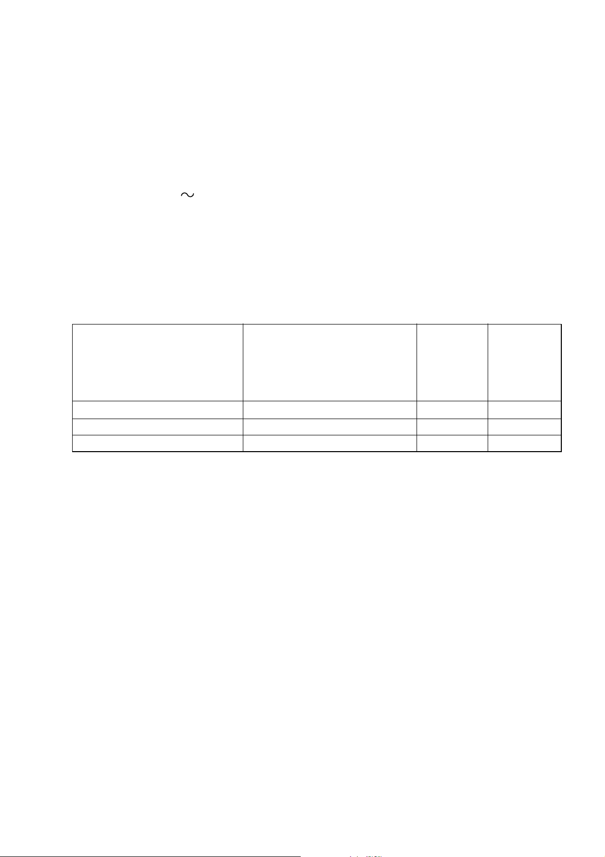
UVX 36 meter distance in cm mW/cm
With regard to the minimum irradiation indicated
below, you should bear in mind that this is not an
absolute value at which the lamps must be
replaced.
Depending on the skin type, the tanning session
may also be extended so that the lamps can be
used a little longer.
output in output in
NEW MIN
(approx) (approx)
2
mW/cm2
Couch 0 cm from acrylic sheet couch 8.7 5.5
Canopy 20 cm from acrylic sheet 8.7 5.5
Canopy beneath the facial tanner 20 cm from acrylic sheet 8.7 5.5
 Loading...