

Philips Grind & Brew HD7762 Service Manual
Coffeemaker Grind & Brew
HD7762
Philips Consumer Lifestyle
Service Manual
PRODUCT INFORMATION
Safety
• This product meets the requirements regarding
interference suppression on radio and TV.
• After the product has been repaired, it should function
properly and has to meet the safety requirements as
officially laid down at this moment.
TECHNICAL INFORMATION
• Voltage : 220-240V
• Frequency : 50 Hz
• Power consumption : 1000W
• Color setting : Black / Metal
• Dimensions
Appliance H x W x D : 440 x 210 x 310 mm
F-Box L x W x H : 320 x 280 x 505 mm
• Cord length : 0,8 m
• Filter size : 1x4
• Contents
Jug (max.) : 1320 mL
Water container (min.) : 264 mL (2 cups)
Water container (max.) : 1320 mL (10 cups)
Avg. water loss during brew process : 10%
• Materials
Appliance : PP
Metal wrap : Stainless steel
Jug : Glass
Hoses : Silicon
• Brew time (max.) : 10 min
• Temperature (full jug) : > 80 °C
• Keep warm time : 120 minutes
Published by Philips Consumer Lifestyle Printed in the Netherlands © Copyright reserved Subject to modification
13/04
TECHNICAL INFORMATION
De-scaling
When the appliance indicates it needs to be descaled,
operate the coffeemaker a few times with vinegar or with
a 10-15% solution of either vinegar (acetic acid), citric acid
or tartar acid, into cold tap water.
Use a paper lter to catch any particles coming out.
Do not use other de-scaling agents as these may harm the
appliance.
If this procedure does not restore the function, then switch
off the coffeemaker when the acid is passing through. Keep
the appliance in this condition overnight and continue/
repeat the cleaning operation.
After the de-scaling procedure, operate the coffeemaker
twice with tap water in order to rinse any residual
substances.
HD7762
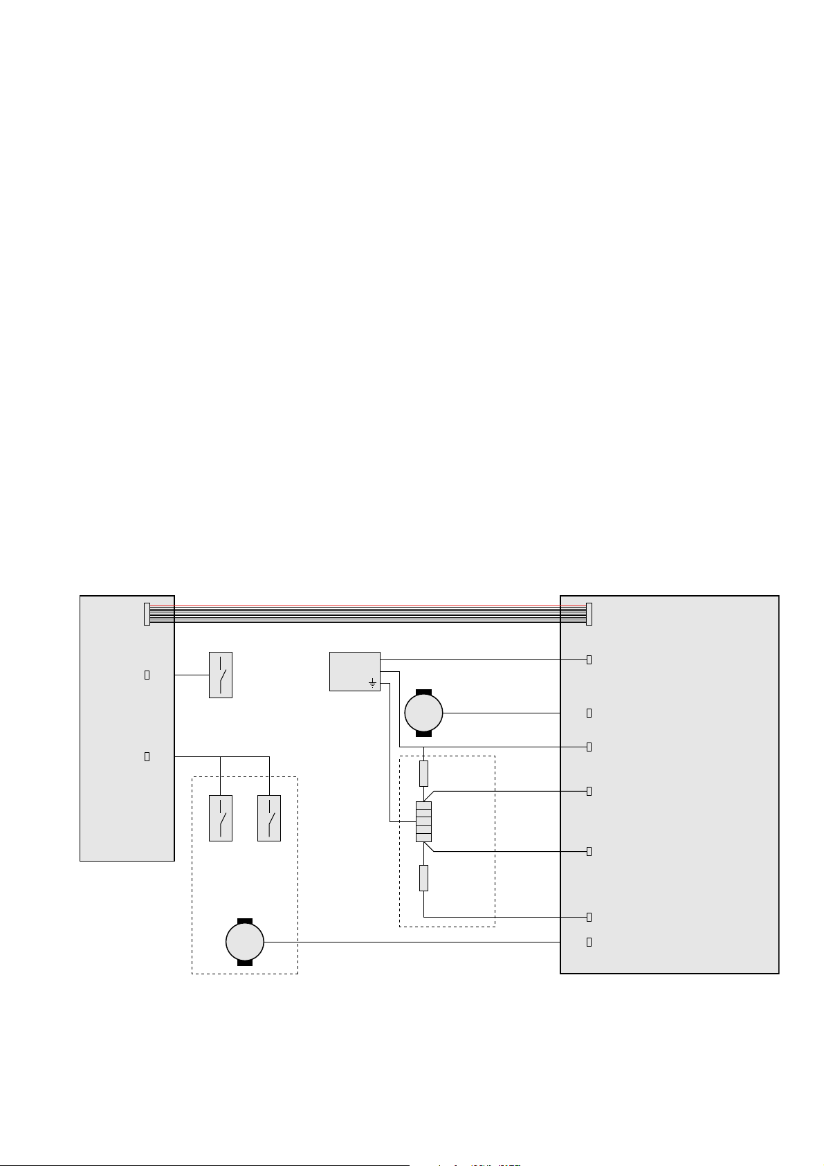
Schematics
UI PCBA
Micro switch
inspection
cover
Micro
switch
M
Micro
switch
Valve
motor
Powe r
cord
CN2CN1
Main PCBA
L
N
M
Grinder
Thermostat
Heater
Fuse
L
Grind motor
N
Warm 1
Warm 2
Heat
Gate motor
2-15

TECHNICAL INFORMATION
HD7762
Self-Check mode
The appliance is equipped with a self-check mode, this enables you to quickly check the function of the main components of
the unit.
Keep the On/Off button pressed while
plugging the mains cord into the socket.
Hardware version CH 201
Press any other button
Software version CH 0004
Press any other button
Heating element enabled CH 1
Press any other button
Heating element disabled CH 2
Press any other button
Grinder motor enabled CH 3
Press any other button
Grinder motor disabled + 6 Beeps CH 4
Press any other button
Microcontroller check CH 5 = ok E1 = Nok
Press any other button
Zero-cross detection CH 6 = ok E2 = Nok
Press any other button
Valve micro switches CH CLO = valve is closed
Press any other button CH ---- = valve is working
Inspection window micro switch L- = Closed 8
Press any other button H- = Open 8
Thermostat CH 1111 = Thermostat closed
Press any other button CH 0000 = Thermostat open
Rotary knob 2 9
Press any other button
Rotary knob rotate clockwise Increasing 9
Rotary knob rotate anti-clockwise Decreasing 9
LED check All digits on All digits on
Press any other button
LED check All digits off All digits off
Press On/Off button
Stand-by
Left side
display
CH OPE = valve is open
Right side display
3-15

REPAIR INSTRUCTION
Repair of this appliance should be carried out on part and or assembly level, most repairs can be allocated to a couple of main
components:
• Bean container and duo-bean mechanics
Disassembly instructions until Step 1.
• User interface assy
Disassembly instructions until Step 4.
When in the UI panel itself has been disassembled, please make sure the wire and flat cable seal is properly installed.
Upon reinstallation of the complete panel, please make sure the seal underneath the UI panel is put back.
• Main PCBA
Disassembly instructions until Step 4.
When only the PCBA needs replacement, skip steps 1 - 3. Upon reinstallation of the PCBA, please make sure the PCBA
holder slides back into its guiding recesses. Please note the position of the Grinder (DC-motor), and Synchro-motor
(AC-motor) leads, when reversed the appliance will not start up.
• Grinder
Disassembly instructions until Step 6, skip step 3 and 5.
It is not advisable to disassemble the grinder, as this will disrupt the grinders’ calibration. In production special tools are
used to adjust the grind-fineness to the optimal level.
HD7762
• Synchro motor + valve and seal
Disassembly instructions until Step 6, skip step 3 and 5.
When the valve and or seal have been removed, please make sure that the seal does not get damaged, and that the seal gets
reinstalled correctly. The seal is critical to seal the grinder from steam coming from the coffee filter.
• Heater, bottom water supply
Disassembly instructions Step 4 and 5.
It is not advisable to disassemble the heater from the keep-warm plate. Heat-conductive paste should be applied to ensure
optimal heat transfer from the element to the plate, jug and coffee.
• Top water supply
Disassembly instructions Step 1 and 2.
The Silicon hose between the elbow joint and the showerhead does not need to be removed to uninstall this component,
when the hose does need replacement, make sure the hose clamps are put back properly, this is to prevent leakage.
When the showerhead has been removed it should be cleaned from any residual liquid gasket and new liquid gasket
(supplied in tubes of 45 g.) should be applied to ensure a proper seal.
• Complete Base, incl. metal wrap
Disassembly instructions Step 4 and 5.
The main PCBA and Heater assy need to be taken out completely, the base is screwed to the top by means of 6 screws.
4-15
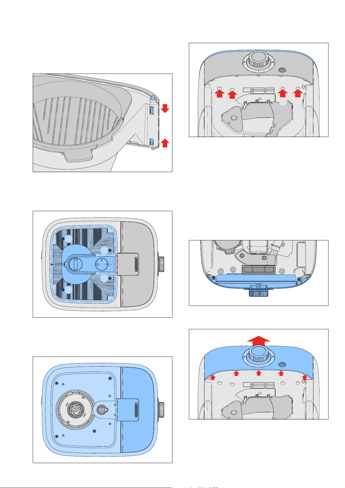
DISASSEMBLY INSTRUCTIONS
Remove all removable and detachable items like the Bean
container lid, jug, lter holder and brush. The lter door
can be removed for convenience by undoing both latches
on the top and bottom side of the hinge.
HD7762
Step 1: Bean container removal
To remove the complete bean container, including DuoBean feature, remove the 4 screws (C) inside the bean
container.
C
C
G
G
Please note the cable connecting to the Inspection window
detection switch. The Water Level Indicator (WLI) cannot
be removed without damaging the Top cover. When the
top cover needs to be replaced the WLI can be reused,
when the WLI needs to be replaced a new top cover needs
to be ordered as well.
Step 3: UI panel removal
To be able to remove the UI panel, you need to disconnect
the leads to the Synchro motor, and the atcable to the
main PCBA. The UI panel is held in place by two screws
accessible from the top side of the appliance, and 5 clicks
accessible from the bottom side of the UI panel. Unscrew
both screws (J).
G G
C
C
Step 2: Top cover removal
The top cover can be opened by removing the four screws
(F) located underneath the Bean container and the four
screws (G) accessible from the underside of the UI panel.
F
F
F
F
J
Undo the snaps by tracing the curve of the UI panel with a
at-head screwdriver, while pulling the UI panel upwards.
The UI panel can be disassembled, the rotary knob can
simply be pulled off, the rotary encoder is secured by a
single nut, remove the nut. The PCBA cover is held in place
by six screws (L), once unscrewed the PCBA can be taken
out. Please mind the rubber seal, preventing steam from
reaching the UI PCBA.
J
5-15
 Loading...