

Page 1

1PHILIPS GR 2.4 Chassis
Recommended Safety Parts
Item Part No. Description
4822 265 30389 2P male vert yellow
4822 265 30877 3P male vert
4822 267 60243 Euroconnector (scart) blue
4822 256 92053 Fuse holder
1240 4822 252 51174 Fuse 1.6A 65V
1242 4822 252 51174 Fuse 1.6A 65V
1534 4822 252 51172 Fuse 3.15A 65V
1559 4822 252 51173 Fuse 1A 65V
1580 4822 252 51174 Fuse 1.6A 65V
1600 4822 070 32502 Fuse 2.5A 65V
1601 4822 252 51175 Fuse 2.5A 65V
2005 4822 124 40196 220µF 20% 16V
2231 4822 124 41525 100µF 20% 25V
2319 4822 122 32442 10nF 50V
2328 4822 122 32442 10nF 50V
2329 4822 122 32442 10nF 50V
2348 4822 124 40196 220µF 20% 16V
2350 4822 124 40433 47µF 20% 25V
2476 4822 122 32442 10nF 50V
2503 4822 122 32442 10nF 50V
2545 4822 126 12273 1200pF 10%R(HR) 2KV
2545 4822 126 12274 1500pF 10%R(HR) 2KV
2546 4822 121 70434 11nF 5% 1.6KV
2546 4822 121 70538 13nF 5% 1.6KV
2547 4822 121 42934 27nF 10% 400V
2547 5322 121 44219 47nF 10% 400V
2549 4822 121 42074 470 nF 10% 400V
2550 4822 121 51528 470nF 5% 250V
2550 5322 121 44128 680nF 10% 250V
2560 4822 121 51408 33nF 10% 250V
2600 4822 121 70285 470nF 10% 250V
2605 4822 124 80728 150µF 20% 385V
2607 4822 121 51469 1nF 400V
2625 4822 126 12272 1nF 10%R(HR) 2KV
2626 4822 126 12267 470pF 10%R(HH) 2KV
2632 4822 126 11382 1nF 10%1KV
2707 4822 122 32442 10nF 50V
2713 4822 124 41525 100µF 20% 25V
3001 4822 052 10399 39Ω 5% 0.33W
3203 4822 116 52233 10k 5% 0.5W
3208 4822 116 52263 2k7 5% 0.5W
3209 4822 116 52263 2k7 5% 0.5W
3231 4822 051 10472 4k7 2% 0.25W
3240 4822 052 10828 8Ω2 5% 0.33W
3241 4822 052 10828 8Ω2 5% 0.33W
3244 4822 051 10103 10k 2% 0.25W
3245 4822 051 10103 10k 2% 0.25W
3306 4822 116 S2233 10k 5% 0.5W
3310 4822 051 10472 4k7 2% 0.25W
3311 4822 051 10103 10k 2% 0.25W
3314 4822 116 52233 10k 5% 0.5W
3319 4822 051 10103 10k 2% 0.25W
3329 4822 116 52256 2k2 5% 0.5W
3334 4822 053 11279 27Ω 5% 2W
3336 4822 052 10479 47Ω 5% 0.33W
3342 4822 051 10103 10k 2% 0.25W
3347 4822 116 S2219 330Ω 5% 0.5W
3348 4822 116 52219 330 Ω 5% 0.5W
3349 4822 116 52219 330 Ω 5% 0.5W
3356 4822 050 21008 1 Ω 1% 0.6W
3359 4822 116 52219 330 Ω 5% 0.5W
3370 4822 051 10472 4k7 2% 0.25W
3456 4822 051 10103 10k 2% 0.25W
3470 4822 116 52233 10k 5% 0.5W
3479 4822 116 52219 330 Ω 5% 0.5W
3481 4822 116 52283 4k7 5% 0.5W
3482 4822 116 52283 4k7 5% 0.5W
3483 4822 052 10339 33Ω 5% 0.33W
3502 4822 053 10122 1k2 5% 1W
3502 4822 053 10272 2k7 5% 1W
3503 4822 052 10128 1 Ω2 5% 0.33W
3503 4822 052 10478 4 Ω7 5% 0.33W
3513 4822 053 10331 330 Ω 5% 1W
3520 4822 116 52283 4k7 5% 0.5W
3551 4822 050 25601 560 Ω 1% 0.6W
3552 4822 050 25601 560 Ω 1% 0.6W
3553 4822 052 10561 560 Ω 5% 0.33W
3570 4822 052 10688 6 Ω8 5% 0.33W
3588 4822 052 10271 270 Ω 5% 0.33W
3589 4822 052 10271 270 Ω 5% 0.33W
3590 4822 116 52272 330k 5% 0.5W
3604 4822 113 80593 1.5 Ω 10% 5W
3606 4822 052 10102 1k 5% 0.33W
3610 4822 052 10688 6 Ω8 5% 0.33W
3610 4822 052 10828 8 Ω2 5% 0.33W
3616 4822 050 24708 4 Ω7 1% 0.6W
3621 4822 053 12279 27Ω 5% 3W
3678 4822 116 52283 4k7 5% 0.5W
3682 4822 053 10561 560 Ω 5% 1W
3706 4822 051 10103 10k 2% 0.25W
3708 4822 051 10103 10k 2% 0.25W
3709 4822 116 52283 4k7 5% 0.5W
3718 4822 116 52215 220 Ω 5% 0.5W
4822 502 13712 Screw 12x3
Recommended Safety Parts
Item Part No. Description
3719 4822 116 52215 220 Ω 5% 0.5W
3721 4822 051 10103 10k 2% 0.25W
3722 4822 051 10103 10k 2% 0.25W
3724 4822 051 10103 10k 2% 0.25W
3725 4822 051 10103 10k 2% 0.25W
3727 4822 116 52217 27Ω 5% 0.5W
3734 4822 116 52283 4k7 5% 0.5W
3743 4822 051 10472 4k7 2% 0.25W
3750 4822 051 10472 4k7 2% 0.25W
3753 4822 116 52283 4k7 5% 0.5W
3759 4822 051 10103 10k 2% 0.25W
3779 4822 116 52233 10k 5% 0.5W
3780 4822 051 10103 10k 2% 0.25W
3781 4822 051 10472 4k7 2% 0.25W
3851 4822 116 83953 75Ω 5% 0.125W
3852 4822 116 83953 75Ω 5% 0.125W
3853 4822 116 83953 75Ω 5% 0.125W
3854 4822 116 83953 75Ω 5% 0.125W
3867 4822 116 52283 4k7 5% 0.5W
3886 4822 051 10472 4k7 2% 0.25W
3890 4822 051 10103 10k 2% 0.25W
5534 4822 157 62771 Coil 90
5534 4822 158 10728 Coil 110
5541 4822 157 63078 Driver transformer
5545 4822 140 10499 LOT-21”-90
5545 4822 140 10501 LOT 25”/28” BLS
5549 4822 157 53069 Balance coil
5554 4822 156 50097 Linearity coil LC90
5554 4822 157 63079 Linearity coil AT4042
5563 4822 157 51462 10µH
5588 4822 157 53252 Coil
5606 4822 157 53995 100 µH 10%
5625 4822 146 31062 SOPS transformer
6204 4822 130 30621 1N4148
6315 4822 130 30621 1N4148
6322 4822 130 30621 1N4148
6483 4822 130 30621 1N4148
6546 4822 130 83342 BY228
6547 4822 130 41602 BYW95C/20
6549 4822 130 31983 BAT85
6563 4822 130 80915 BYD74C
6591 4822 130 30621 1N4148
6611 5322 130 80442 BZV85-C16
6622 4822 130 30821 1N4148
6624 4822 130 31933 1N5061
6625 4822 130 31933 1N5061
6630 4822 130 33531 BY229F-600
6630 4822 130 81175 BYD74G
6861 4822 130 30621 1N4148
7500 4822 130 41344 BC337-40
7504 4822 130 41344 BC337-40
7540 4822 130 41344 BC337-40
7545 4822 130 61265 BU508AF
7546 5322 130 41982 BC848B
7625 4822 130 62735 BUT12AF
7700 5322 130 41982 BC848B
7703 S322 130 41982 BC848B
7704 S322 130 41982 BC848B
7706 S322 130 41982 BC848B
7707 S322 130 41982 BC848B
3200 4822 OSO 21002 1k 1% 0.6W
3202 4822 050 21002 1k 1% 0.6W
3779 4822 116 52233 10k 5% 0.5W
2344 4822 124 40246 4.7 µF 20% 63V
2411 4822 124 80067 4.7 µF 20% 63V
2433 4822 126 12274 1500pF 10%R(HR) 2KV
2532 4822 124 80067 4.7 µF 20% 63V
3303 4822 051 10242 2k4 2% 0.25W
3306 4822 116 52219 330 Ω 5% 0.5W
3310 4822 116 52219 330 Ω 5% 05W
3311 482205312153 15k 5% 3W
3312 4822 052 10271 270 Ω 5% 0.33W
3313 4822 052 10271 270 Ω 5% 0.33W
3333 4822 116 52263 2k7 5% 0.5W
3340 4822 116 52219 330 Ω 5% 0.5W
3341 4822 053 12153 15k 5% 3W
3342 4822 052 10271 270w 5% 0.33W
3343 4822 052 10271 270 Ω 5% 0.33W
3364 4822 051 10472 4k7 2% 0.25W
3370 4822 116 52219 330 Ω 5% 0.5W
3371 4822 053 12153 15k 5% 3W
3372 4822 052 10271 270 Ω 5% 0.33W
3373 4822 052 10271 270 Ω 5% 0.33W
3431 4822 052 10181 180 Ω 5% 0.33W
3431 4822 052 10271 270 Ω 5% 0.33W
3432 4822 052 10229 22Ω 5%0.33W
3433 4822 052 10128 1 Ω2 5%0.33W
3433 4822 052 10188 1 Ω8 5%0.33W
3443 4822 051 10242 2k4 2% 0.25W
3532 4822 051 10103 10k 2% 0.25W
3534 4822 052 10828 8 Ω2 5% 0.33W
3580 4822 051 10103 10k 2% 0.25W
6421 4822 130 30621 1N4148
7303 5322 130 41982 BC848B
4822 255 70261 CRT-socket
o
o
o
Recommended Safety Parts
Item Part No. Description
7333 5322 130 41982 BC848B
7363 5322 130 41982 BC848B
7537 5322 130 41982 BC848B
7538 5322 130 41982 BC848B
1816 4822 252 51169 Fuse 250mA
2201 4822 124 40433 47µF 20% 25V
2203 4822 124 40433 47µF 20% 25V
2211 4822 124 40433 47µF 20% 25V
2212 4822 124 40433 47µF 20% 25V
2807 4822 124 40246 4.7 µF 20% 63V
2808 4822 124 40246 4.7 µF 20% 63V
2813 4822 124 40246 4.7 µF 20% 63V
2833 4822 124 40196 220 µF 20% 16V
2835 4822 124 40246 4.7 µF 20% 83V
2900 4822 124 40246 4.7 µF 20% 63V
2901 4822 124 40433 47µF 20% 25V
2910 4822 122 33177 10nF 20% 50V
2917 4822 122 33177 10nF 20% 50V
2925 4822 122 33177 10nF 20% 50V
3208 4822 116 52272 330k 5% 0.5W
3800 4822 116 83953 75Ω 5% 0.125W
3808 4822 116 83953 75Ω 5% 0.125W
3810 4822 116 83953 75Ω 5% 0.125W
3818 4822 116 52199 68Ω 5% 0.5W
3826 4822 052 10159 15Ω 5% 0.33W
3834 4822 053 10221 220 Ω 5% 1W
3846 4822 116 52215 220 Ω 5% 0.5W
3849 4822 051 20109 10Ω 5% 0.1W
3890 4822 051 20472 4k7 5% 0.1W
3891 4822 051 20472 4k7 5% 0.1W
3892 4822 051 20472 4k7 5% 0.1W
3895 4822 116 83953 75Ω 5% 0.125W
3897 4822 116 83953 75Ω 5% 0.125W
3900 4822 052 10279 27Ω 5% 0.33W
3914 4822 116 52219 330 Ω 5% 0.5W
6920 4822 130 30621 1N4148
6921 4822 130 30621 1N4148
7805 4822 130 41344 BC337-40
2661 4822 124 40433 47µF 20% 25V
3625 4822 053 21564 560k 5% 0.5W
3649 4822 050 23309 330k 5% 0.5W
3658 4822 052 10688 6R8 5% 0.33W
3665 4822 051 10822 8k2 2% 0.25W
3665 4822 051 10123 12k 2% 0.25W
3672 4822 051 10103 10k0 2% 0.25W
2420 4822 122 33177 10nF 20% 50V
2421 4822 122 33177 10nF 20% 50V
2423 4822 122 33177 10nF 20% 50V
2005 5322 126 10223 4.7nF 10% 63V
2007 5322 126 10223 4.7nF 10% 63V
2010 4822 124 40246 4.7 µF 20% 63V
2010 4822 124 40433 47µF 20% 25V
2012 4822 122 33177 10nF 20% 50V
2016 4822 122 33177 10nF 20% 50V
2102 5322 126 10223 4.7nF 10% 63V
2103 5322 126 10223 4.7nF 10% 63V
2106 5322 126 10223 4.7nF 10% 63V
2108 5322 126 10223 4.7nF 10% 63V
2202 4822 122 33177 10nF 20% 50V
2205 4822 122 33342 33nF 10% 63V
2208 4822 122 33342 33nF 10% 63V
2215 4822 124 40196 220 µF 20% 16V
2216 4822 124 40246 4.7 µF 20% 63V
2218 4822 124 40433 47µF 20% 25V
2219 4822 124 40246 4.7 µF 20% 63V
2220 4822 124 40196 220 µF 20% 16V
2221 4822 124 40196 220 µF 20% 1 6V
2308 5322 122 34123 1nF 10% 50V
2313 4822 124 40433 47µF 20% 25V
2320 4822 122 33172 390pF 5% 50V
2321 5322 122 34123 1nF 10%50V
2322 4822 122 33177 10nF 20% 50V
2323 5322 122 32654 22nF 10% 63V
2325 5322 122 34123 1nF 10% 50V
2328 4822 122 33177 10nF 20% 50V
2333 4822 122 33177 10nF 20% 50V
2336 4822 124 40433 47µF 20% 25V
2340 4822 122 33177 10nF 20% 50V
2343 5322 122 32654 22nF 10% 63V
2344 5322 122 32654 22nF 10% 63V
3026 4822 052 10109 10Ω 5% 0.33W
3208 4822 052 10181 180 Ω 5% 0.33W
3234 4822 052 10181 180 Ω 5% 0.33W
3301 4822 051 20109 10Ω 5% 0.1W
2978 4822 124 40246 4.7 µF 20% 63V
3953 4822 116 52269 3k3 5% 0.5W
3954 4822 116 52269 3k3 5% 0.5W
3972 4822 116 52233 10k 5% 0.5W
3985 4822 116 52256 2k2 5% 0.5W
4822 267 50721 9P male white
4822 267 60243 Euroconnector blue
4822 267 40624 5P male vert white
4822 267 50721 9P male white
Recommended Safety Parts
Item Part No. Description
For 16:9 only
1240 4822 252 51174 Fuse 1.6A
1242 4822 252 51174 Fuse 1.6A
1534 4822 252 51172 Fuse 3.15A
1559 4822 252 51173 Fuse 1A
1580 4822 252 51174 Fuse 1.6A
1600 4822 070 32502 Fuse 2.5A
1601 4822 252 51175 Fuse 2.5A
2005 4822 124 40196 220 µF 20% 16V
2231 4822 124 41525 100 µF 20% 25V
2319 4822 122 32442 10nF 50V
2328 4822 122 32442 10nF 50V
2329 4822 122 32442 10nF 50V
2348 4822 124 40196 220 µF 20% 16V
2350 4822 124 40433 47µF 20% 25V
2476 4822 122 32442 10nF 50V
2503 4822 122 32442 10nF 50V
2545 4822 126 12274 1500pF 10%R(HR) 2KV
2546 4822 121 70434 11nF 5% 1.6KV
2546 4822 121 70538 13nF 5% 1.6KV
2546 4822 121 70545 7.5nF 5% 1.6KV
2547 4822 121 40488 22nF 10% 400V
2547 4822 121 42934 27nF 10% 400V
2547 5322 121 44219 47nF 10% 400V
2549 4822 121 42074 470nF 10% 400V
2550 4822 121 42365 330nF 5% 250V
2550 4822 121 51528 470nF 5% 250V
2550 5322 121 44128 680nF 10% 250V
2560 4822 121 51408 33nF 10% 250V
2600 4822 121 70285 470nF 10% 250V
2605 4822 124 80728 150kF 20% 385V
2607 4822 121 51469 1nF 400V
2607 4822 126 13474 2.2nF 20% 400V
2626 4822 126 12267 470pF 10%R(HR) 2KV
2632 4822 126 11382 1nF 10%1KV
2707 4822 122 32442 10nF 50V
2713 4822 124 41525 100 µF 20% 25V
3001 4822 052 10399 39Ω 5% 0.33W
3231 4822 051 10472 4k7 2% 0.25W
3240 4822 052 10828 8 Ω2 5% 0.33W
3241 4822 052 10828 8 Ω2 5% 0.33W
3244 4822 051 10103 10k 2% 0.25W
3245 4822 051 10103 10k 2% 0.25W
3310 4822 051 10472 4k7 2% 0.25W
3311 4822 051 10103 10k 2% 0.25W
3319 4822 051 10103 10k 2% 0.2SW
3334 4822 053 11279 27Ω 5% 2W
3336 4822 052 10479 47Ω 5% 0.33W
3342 4822 051 10103 10k 2% 0.25W
3356 4822 050 21008 1 Ω 1%0.6W
3370 4822 051 10472 4k7 2% 0.25W
3456 4822 051 10103 10k 2% 0.25W
3483 4822 052 10339 33Ω 5% 0.33W
3502 4822 053 10122 1k2 5% 1W
3502 4822 053 10272 2k7 5% 1W
3503 4822 052 10128 1 Ω2 5% 0.33W
3503 4822 052 10156 1 Ω5 5% 0.33W
3503 4822 052 10478 4 Ω7 5% 0.33W
3513 4822 053 10331 330 Ω 5% 1W
3551 4822 050 25601 560 Ω 1% 0.6W
3552 4822 050 25601 560 Ω 1% 0.6W
3553 4822 052 10561 560 Ω 5% 0.33W
3570 4822 052 10688 6 Ω8 5% 0.33W
3588 4822 052 10271 270 Ω 5% 0.33W
3589 4822 052 10271 270 Ω 5% 0.33W
3604 4822 113 80593 1.5 Ω 10% 5W
3606 4822 052 10102 1k 5% 0.33W
3610 4822 052 10688 6 Ω8 5% 0.33W
3610 4822 052 10828 8 Ω2 5% 0.33W
3616 4822 050 24708 4 Ω7 1% 0.6W
3616 4822 157 52265 COIL
3621 4822 053 12279 27Ω 5% 3W
3682 4822 053 10561 560 Ω 5% 1W
3706 4822 051 10103 10k 2% 0.25W
3708 4822 051 10103 10k 2% 0.25W
3721 4822 051 10103 10k 2% 0.25W
3722 4822 051 10103 10k 2% 0.25W
3724 4822 051 10103 10k 2% 0.25W
3725 4822 051 10103 10k 2% 0.25W
3743 4822 051 10472 4k7 2% 0.25W
3750 4822 051 10472 4k7 2% 0.25W
3759 4822 051 10103 10k 2% 0.25W
3780 4822 051 10103 10k 2% 0.25W
3781 4822 051 10472 4k7 2% 0.25W
3851 4822 116 83953 75Ω 5% 0.125W
3852 4822 116 83953 75Ω 5% 0.125W
3853 4822 116 83953 75Ω 5% 0.125W
3854 4822 116 83953 75Ω 5% 0.125W
3886 4822 051 10472 4k7 2% 0.25W
4822 265 30389 2P male vert yellow
4822 265 30877 3P male vert
4822 267 60243 21p scart
4822 502 13712 Screw 12x3
4822 256 92053 Fuse holder
Recommended Safety Parts
Item Part No. Description
3890 4822 051 10103 10k 2% 0.25W
5534 4822 157 62771 Coil 90
5534 4822 158 10728 Coil 110
5541 4822 157 63078 Driver transformer
5545 4822 140 10499 LOT-21”-90
5545 4822 140 10501 LOT 25”/28”BLS/16/9
5545 4822 140 10503 LOT 21”-110
5545 4822 140 10515 LOT 29”-superflat
5549 4822 157 53069 Balance coil
5554 4822 156 50097 Linearity LC90
5554 4822 157 63079 Linearity AT4042
5563 4822 157 51462 10µH
5588 4822 157 53252 22µH
5606 4822 157 53995 100µH
5625 4822 146 31062 Power trafo 21”
5625 4822 148 81401 Power trafo
6204 4822 130 30621 1N4148
6304 4822 130 30621 1N4148
6315 4822 130 30621 1N4148
6322 4822 130 30621 1N4148
6483 4822 130 30621 1N4148
6546 4822 130 83342 BY228-RAP15/10
6547 4822 130 41602 BYW95C/20
6549 4822 130 31983 BAT85
6563 4822 130 80915 BYD74C
6591 4822 130 30621 1N4148
6611 5322 130 80442 BZV85-C16
6622 4822 130 30621 1N4148
6624 4822 130 31933 1N5061
6625 4822 130 31933 1N5061
6630 4822 130 33531 BY229F-600
6630 4822 130 81175 BYD74G
6697 4822 130 31631 BYV10-20
6699 4822 130 31631 BYV10-20
6861 4822 130 30621 1N4148
7500 4822 130 41344 BC337-40
7504 4822 130 41344 BC337-40
7540 4822 130 41344 BC337-40
7545 4822 130 6126S BU508AF
7545 4822 130 63666 BU2520DF
7546 5322 130 41982 BC848B
762S 4822 130 6273S BUT12AF
7700 5322 130 41982 BC848B
7703 5322 130 41982 BC848B
7704 5322 130 41982 BC848B
7706 5322 130 41982 BC848B
7707 5322 130 41982 BC848B
2344 4822 124 40246 4.7µF 20% 63V
2411 4822 124 80067 4.7µF 20% 63V
2433 4822 126 12274 1500pF 10%R(HR) 2KV
2435 4822 126 12274 1500pF 10%R(HR) 2KV
2532 4822 124 80067 4.7µF 20% 63V
2533 4822 124 40246 4.7µF 20% 63V
3303 4822 051 10242 2k4 2% 0.25W
3311 4822 053 12153 15k 5% 3W
3312 4822 052 10271 270 Ω 5% 0.33W
3313 4822 052 10271 270 Ω 5% 0.33W
3341 4822 053 12153 15k 5% 3W
3342 4822 052 10271 270 Ω 5% 0.33W
3343 4822 052 10271 270 Ω 5% 0.33W
3364 4822 051 10472 4k7 2% 0.25W
3371 4822 053 12153 15k 5% 3W
3372 4822 052 10271 270 Ω 5% 0.33W
3373 4822 052 10271 270 Ω 5% 0.33W
3431 4822 052 10181 180 Ω 5% 0.33W
3431 4822 052 10271 270 Ω 5% 0.33W
3432 4822 052 10129 12Ω 5% 0.33W
3432 4822 052 10229 22Ω 5% 0.33W
3433 4822 052 10108 1Ω 5% 0.33W
3433 4822 052 10128 1Ω2 5% 0.33W
3433 4822 052 10188 1Ω8 5% 0.33W
3443 4822 051 10242 2k4 2% 0.25W
3452 4822 051 10103 10k 2% 0.25W
3512 4822 051 10103 10k 2% 0.25W
3518 4822 051 10103 10k 2% 0.25W
3532 4822 051 10103 10k 2% 0.25W
3534 4822 052 10828 8Ω2 5% 0.33W
3580 4822 051 10103 10k 2% 0.25W
6304 4822 130 30621 1N4148
6421 4822 130 30621 1N4148
7303 5322 130 41982 BC848B
7333 5322 130 41982 BC848B
7363 5322 130 41982 BC848B
7412 5322 130 41982 BC848B
7423 5322 130 41982 BC848B
7537 5322 130 41982 BC848B
7538 5322 130 41982 BC848B
2506 4822 124 40433 47LF 20% 25V
3506 4822 052 10399 390 5% 0.33W
3519 4822 050 24708 407 1% 0.6W
4822 267 31858 1 P female
4822 255 70261 CRT holder
o
o
o
o
25”/28”/29”/21”-110
o
Recommended Safety Parts
Item Part No. Description
4822 267 60243 21 P scart (blue)
4822 267 50721 9P male white
1816 4822 252 51169 Fuse 250mA
2201 4822 124 40433 47µF 20% 25V
2203 4822 124 40433 47µF 20% 25V
2211 4822 124 40433 47µF 20% 25V
2212 4822 124 40433 47µF 20% 25V
2803 4822 122 33342 33nF 10% 63V
2807 4822 124 40246 4.7µF 20% 63V
2808 4822 124 40246 4.7µF 20% 63V
2833 4822 124 40196 220µF 20% 16V
2835 4822 124 40246 4.7µF 20% 63V
2837 5322 122 32269 6.8pF 5% 50V
2900 4822 124 40246 4.7µF 20% 63V
2901 4822 124 40433 47µF 20% 25V
2910 4822 122 33177 10nF 20% 50V
2917 4822 122 33177 10nF 20% 50V
2925 4822 122 33177 10nF 20% 50V
3800 4822 116 83953 75Ω 5% 0.125W
3808 4822 116 83953 75Ω 5% 0.125W
3810 4822 116 83953 75Ω 5% 0.125W
3826 4822 052 10159 15Ω 5% 0.33W
3834 4822 053 10221 220Ω 5% 1W
3849 4822 051 20109 10Ω 5% 0.1W
3858 4822 051 20472 4k7 5% 0.1W
3867 4822 116 83953 75Ω 5% 0.125W
3890 4822 051 20472 4k7 5% 0.1W
3891 4822 051 20472 4k7 5% 0.1W
3892 4822 051 20472 4k7 5% 0.1W
3895 4822 116 83953 75Ω 5% 0.125W
3897 4822 116 83953 75Ω 5% 0.125W
3900 4822 052 10279 27Ω 5% 0.33W
3900 4822 052 10828 8Ω2 5% 0.33W
6920 4822 130 30621 1N4148
6921 4822 130 30621 1N4148
7805 4822 130 41344 BC337-40
2005 5322 126 10223 4.7nF 10% 63V
2007 5322 126 10223 4.7nF 10% 63V
2010 4822 124 40246 4.7µF 20% 63V
2010 4822 124 40433 47µF 20% 25V
2012 4822 122 33177 10nF 20% 50V
2106 5322 126 10223 4.7nF 10% 63V
2108 5322 126 10223 4.7nF 10% 63V
2202 4822 122 33177 10nF 20% 50V
2205 4822 122 33342 33nF 10% 63V
2208 4822 122 33342 33nF 10% 63V
2215 4822 124 40196 220µF 20%16V
2216 4822 124 40246 4.7µF 20%63V
2218 4822 124 40433 47µF 20% 25V
2219 4822 124 40246 4.7µF 20% 63V
2220 4822 124 40196 220µF 20% 16V
2221 4822 124 40196 220µF 20%16V
2308 5322 122 34123 1nF 10% 50V
2313 4822 124 40433 47µF 20% 25V
2320 4822 122 33172 390pF 5% 50V
2321 5322 122 34123 1nF 10% 50V
2322 4822 122 33177 10nF 20% 50V
2323 5322 122 32654 22nF 10% 63V
2325 5322 122 34123 1nF 10% 50V
2328 4822 122 33177 10nF 20% 50V
2333 4822 122 33177 10nF 20% 50V
2336 4822 124 40433 47µF 20% 25V
2340 4822 122 33177 10nF 20% 50V
2343 5322 122 32654 22nF 10% 63V
2344 5322 122 32654 22nF 10% 63V
3208 4822 052 10181 180Ω 5% 0.33W
3234 4822 052 10181 180Ω 5% 0.33W
3301 4822 051 20109 10Ω 5% 0.1W
2500 4822 124 41525 100µF 20% 25V
3500 4822 052 10228 2µ2 5% 0.33W
3511 4822 052 10108 1Ω 5% 0.33W
3512 4822 052 10108 1Ω 5% 0.33W
3513 4822 052 10108 1Ω 5% 0.33W
3514 4822 052 10108 1Ω 5% 0.33W
5501 4822 157 53252 Coil
5505 4822 157 53252 Coil
2513 5322 122 34123 1nF 10% 50V
2514 4822 121 51528 470nF 5% 250V
2522 5322 122 34123 1nF 10% 50V
2531 5322 122 34123 1nF 10% 50V
2532 5322 122 34123 1nF 10% 50V
3515 4822 052 10479 47Ω 5% 0.33W
3551 4822 050 25601 560Ω 1% 0.6W
3552 4822 050 25601 560Ω 1% 0.6W
3553 4822 052 10561 560Ω 5% 0.33W
3557 4822 051 20472 4k7 5% 0.1W
4822 267 40624 5P male
4822 267 40985 6P male black
4822 267 40985 6P male (Y71)
16:9 Module / Comb Filter / Controls PCB / Directions for use / Electrical Adjustments ...Cont’d / Eurotext Module / Microprocessing Listing / Nicam BGL IF (J)
Nicam BGL IF (K) / Nicam Module (J) / Nicam Module (K) / Power Supply / Safety Parts / Scan Velocity Modulation / Scanning Module / SOPS Module / Video Processing
Stereo IF Module (L) / Stereo IF Module (M) / Testpoint Overview / Text (F1) / Text (F2) / Third Scart / Tube Base / Tube Base 16:9 / Tuner IF Audio Amp / Waveforms / Wiring Diagram
Page 2

PHILIPS GR 2.4 Chassis
2
Electrical
Adjustments
Setting conditions
All electrical settings should be made under the
following conditions:
* supply voltage: 220 -240 V ± 10%;50 Hz ± 5%
* warming-up time 10 minutes
* the voltages and oscillograms have been
measured with regard to tuner earth.
* measuring probe: Ri > 10 MΩ; Ci < 2.5 pF.
1. Settings on the carrier board
1.1 +1 48V/+95V supply voltage
Connect a voltmeter over C2631. Using R3635,
set the supply voltage to +148V ± 0.5V for 25”
and 28” units or to 95V ± 0.5V for 21” units.
1.2 Focusing
This is set using the focusing potentiometer (on
the top of the line output transformer).
1.3 Vg2 setting
Connect a pattern generator and supply a
blanking frame signal (black picture). Switch the
unit to the service default mode (see section 9).
Connect an oscilloscope to the emitters of
transistors 7304 and 7364 on the picture tube
module. Set the oscilloscope to frame frequency. Measure the DC voltage level of the
measuring pulses (see Fig. 7.2). Using the Vg2
potentiometer on the line output transformer, set
the measuring pulse with the lowest DC voltage
level to: * +130V ± 5V for all sets.
1.4 Horizontal synchronization
Connect pin 5-IC7470 to pin 9-IC7470. Supply
an aerial signal and tune the set. Adjust in
service menu(see section 9), sync.freq.by
means of the menu +/- button until the picture is
straight. Remove the interconnection.
1.5 Horizontal centring
Set using potentiometer 3461.
1.6 Vertical centring
Set using potentiometer 3516.
1.7 Picture height
Set using potentiometer 3504.
1.8 Picture width
Set using potentiometer 3525.
1.9 East/west correction
Is adjusted with potentiometer 3521
1.10 Chroma bandpass filter
a. Setting for PAL/SECAM sets (TDA4657)
Connect a signal generator (e.g. PM 5138) to
pin 20 of the euroconnector (EXT1) and set its
frequency to 4.286 MHz/0.5 Vpp. Switch the unit
to EXT1. Connect pin 18-IC7306 to +12V.
Connect an oscilloscope to pin 9-IC7306.
Set 5301 to maximum amplitude. Remove the
interconnection.
b. Setting for PAL sets (TDA4510)
Connect a signal generator (e.g. PM 5138) to
pin 20 of the euroconnector (EXT1) and set its
frequency to 4.436 MHz/0.5Vpp. Connect the
unit to EXT1. Connect an oscilloscope to pin 9IC7305 (TDA4510).
Set 5301 to maximum amplitude
1.11 Chroma auxiliary oscillator
Connect a pattern generator and supply a PAL
colour bar pattern. Connect pin 11-107305
(TDA4510) to earth. Set 2313 so that the colour
on the screen has practically stopped. Remove
the interconnection.
1.12 White balance
Connect a pattern generator and select a white
picture. Switch on the service menu (see section
9) and select “WHITE BALANCE”.
Set the value of “Green” to 50(G/AMP), and the
Value of “Blue” to 45(B/AMP). Value of “Red” to
57(R/AMP). In most cases no futher adjustments are required.
1.13 Peak white limiter
Switch on the service menu (see section 9) and
select “WHITE BALANCE”.
Set “WH/LIM” to the value:
- 35 for blackline units
- 51 for non-blackline units
- 63 for 21” 110 degree sets
- 45 for 29” sets
1.14 Cut-off points of the picture tube
Connect a pattern generator and select a black
picture. Switch on the service menu (see section
9) and select “CUT OFF”. Set the value of “Red”
to 30, and fore “Green” to 30, and for “Blue” to
30. In most cases no futher adjustments are
required.
1.15 Options
Switch on the service menu and select
“OPTIONS” or “OPTION 1”.
Switch the options “ON” and “OFF” according to
whether the following options are present:
- “THIRD SCART” on a set with third scart.
- “TELETEXT” on a teletext set
- “MULTI SYSTEM” for multisystem sets
- “UHF ONLY” for a tuner which can only be
tuned to the UHF band
- “NICAM” for stereo sets which can also receive
NICAM sound.
Fig. 7.2
2.1 RF-AGC
If the picture from a strong local transmitter is
distorted, adjust 3016 until the picture is not
distorted.
2.2a MF-AFC
For multi system sets (PAL-BG/SECAM-DK).
Connect a pattern generator to pin 8 of connector G29 (IF-module) and select a frequency of
38,9 MHz. Connect a voltmeter to pin 11 of
connector G29. Adjust with 5001 the DC voltage
to 1.9 V.
2.2b MF-AFC For all other sets.
Connect a pattern generator to pin 8 of connector G29 (IF-module) and select a frequency of
38,9 MHz. Connect a voltmeter to pin 11 of
connector G29.
Adjust with 5001 the DC voltage to 2.3 V.
2.3 Stereo matrix
Connect a pattern generator and supply a PAL
BG signal with stereo sound. Select only the
right-hand channel sound. Go into service
mode. Choose SND stereo and pull out the right
connector (seen from the front side of the set).
Put volume maximum with volume button. Align
with menu-button so that the sound is just not
hearable in the left loudspeaker. Leave now the
service mode by putting the set in standby.
Error messages
Internal microcomputer errors and external
errors will be signalled by displaying the error
number (by OSD) and by continuous blinking
the LED (video related errors only).
The last five errors will be remembered in the
non volatile memory (if possible), this is called
the error buffer. After a startup of the system (on
by main switch or on from standby) only one
error will be added to the buffer (first in, first out
procedure), only errors different from the last
error in the buffer, will be added to this buffer.
The error will be cleared when the “standby”
command is given while the system is in service
menu mode. An active error is displayed
continuously in service default mode. The buffer
is shown in the service menu mode (Service
main menu).
Electrical Adjustments (16:9)
Service menu
Fig. 7.1 shows the options in the Service Menu
layouts. In the 16/9 model the option “E SIX/
NINE has been added in the “service menu.
For a detailed description of the “service default
mode’ and the ‘service menu” please refer to
chapter 9 in the chassis manual GR2.4 AA.
Default values in option “E SIX./NINE”
The default values are displayed as a two figure
number in the middle of the bar at the bottom of
the picture. The default value can be changed
for the optimum picture dimensions of the set
concerned using the “+” and “-” keys.
Option Default
value
“A HEIGHT” (picture height) 15
“B PARAB (east-west correction 16/9) 04
SIXT./NINE”
“C WIDE” (picture width) 03
“0 PARAB (east-west correction 4/3) 15
FOUR/THREE”
For the default values of the options in the other
menus please refer to chassis manual GR2.4 AA.
Adjustments in 16:9 mode.
Following the replacement of the EEPROM
(IC7710) and/or microprocessor (IC7708)
diagram A. It is necessary to recalibrate the 16/9
adjustments. Use a test circle (antenna signal)
or a convergence pattern (video generator).
The adjustments are now as follows:
Place the set in service mode.
Select “E SIX/NINE” mode.
1. Picture height
Select A (height), adjust the picture with +/menu key in such a manner that the upper and
lower edges just touch the mask. Now centre
the picture using R3516.
2. Picture width
A Select C (wide), adjust the picture with the +/-
menu key so that the picture remains 7 cm
from the mask on both the right and left side.
B Select D (parab four/three), using the +/-
menu key adjust so that the vertical lines are
straight.
C Repeat A if it is necessary!
3. East/west adjustment in 16/9 mode
Select B (parab six./nine), using the +/- menu
key adjust so that the vertical lines are straight.
Now switch to “standby”.
(See Fig. 7.1)
Survey of error messages on the screen
Message Description Possible fault
on screen
PIP 12C error PIP module +5 on PIP module, IC7406
NICA 12C error IC7305(NICAM sets) IC7305, +5 on IF module
9860 12C error IC7204 +5/+8 on IF module, IC7305
9840 12C error IC7205 +5/+8 on IF module, IC7205
TXT 12C error teletext module IC7910/IC7920, +5 on TEXT module
EPROM 12C error IC7710 IC7708/IC7710, +5 on IC’s
TUNE 12C error tuner +5/+14 on tuner, T57003
CHR1 12C error IC7308 +14 on IC7308
CHR2 12C error IC7309 +14 on IC7309
6415 12C error IC7820
BUS + blinking LED 12C bus blocked
Fig. 7.1
Testpoint Overview
Directions for use
1. Service-Default-Mode
The GR2.4 is equipped with a service default
mode. The service default mode is a fixed
defined condition in which the television can be
set.
1.1 Mode definition
The definition of the fixed mode in the service
default mode is as follows:
- all sound and picture adjustments are set in
the middle position (except volume, which is
set at low and zoom set at zero) in 4/3 mode.
- The set is tuned to 475.25 MHz
- system:
* PAL BG or PAL I for single system sets
(MULTI-SYSTEM “OFF”)
* SECAM LIDK for multi-system sets (MULTI-
SYSTEM “ON”)
* SECAM DK for sets for Eastern Europe
(MULTI-SYSTEM “ON”).
* PAL BG for sets for Eastern Europe (MULTI-
SYSTEM “OFF”).
1.2 Service-default-mode
The service default mode is switched on by
briefly short-circuiting the pins M33 and M34
(SERVICE) behind the INSTALL key on the
carrier panel when switching the unit on with the
mains switch. In order to indicate that the unit is
in the service default mode, an “SER” appears
on the screen.
The service default mode can only be switched
off by switching the unit to standby. The set is
switched off and then on again using the mains
switch or mains plug, the service default mode
remains switched on. Searching for transmitter
frequencies begins following the simultaneous
pressing of both ‘install” keys on the remote
control. When the service default mode is
operational the following functions are switched
off:
16:9 Module / Comb Filter / Controls PCB / Directions for use / Electrical Adjustments ...Cont’d / Eurotext Module / Microprocessing Listing / Nicam BGL IF (J)
Nicam BGL IF (K) / Nicam Module (J) / Nicam Module (K) / Power Supply / Safety Parts / Scan Velocity Modulation / Scanning Module / SOPS Module / Video Processing
Stereo IF Module (L) / Stereo IF Module (M) / Testpoint Overview / Text (F1) / Text (F2) / Third Scart / Tube Base / Tube Base 16:9 / Tuner IF Audio Amp / Waveforms / Wiring Diagram
Page 3

3PHILIPS GR 2.4 Chassis
Electrical
Adjustments
Cont’d
Directions for use
- automatic cut-off circuit. The set can be
controlled normally.
1.3 Service menu
- Service menu
The service menu is activated by simultaneously
pressing the “menu” and “-” keys on the local
operating panel. The service menu now appears
on the screen. The service menu offers the
facility to set various options and make a
number of picture tube settings. The various
components in the service menu are selected
using the coloured keys on the remote control.
The adjustment of the various components is
performed with the aid of the “menu +/-” keys on
the remote control. The adjusted values and
options are immediately stored in the EEPROM
when the service menu is exited via “menu on’
or “mainsknob” button. With the “menu” key you
return to the “default service mode”.
Remarks 1:
If a multi-system set is nevertheless to be used
with the PAL BG system in the service default
mode, the option MULTI’ can be temporarily
switched off (“OFF”).
Remarks 2:
If a multi-system set for Eastern Europe is
nevertheless to be used with the PAL BG system
in the service default mode, the option “MULTI’
can be temporarily switched off (“OFF”).
Microprocessing Listing
List of the microprocessors that are used in GR2.X equipment.
LANGUAGE COMBINATIONS:
LO INCLUDES;ENGLISH ONLY
Li INCLUDES;ENGLISH, GERMAN, FRENCH, ITALIAN, DUTCH, PORTUGUES
L2 INCLUDES;ENGLISH, FINNISH, DANNISH, SWEDISH, NORWEGIAN, SPANISH
L3 INCLUDES;ENGLISH, GERMAN, FRENCH, HUNGARIAN, CZECH, RUSSIAN
L5 INCLUDES;ENGLISH, GERMAN, FRENCH, ITALIAN, DUTCH, PORTUGUES, SPANISH
L6 INCLUDES;ENGLISH, FINNISH, DANNISH, SWEDISH, NORWEGIAN, SPANISH
L7 INCLUDES;ENGLISH, GERMAN, FRENCH, HUNGARIAN, CZECH, RUSSIAN, POLISH.
DEV CODE: SUPPLY DESCRIPTION/ X-TAL SERVICE CODE REPLACEMENT
GR2.X CODE LANGUAGE
GR 2.1 FSL1-4.0 U211 STEREO L1 * 4822 209 31209
FSL2-4.0 U209 STEREO L2 * 4822 900 10569
VSL1-4.1 U114 MONO L1 4.19 4822 209 63872
VSL2-4.1 U111 MONO L2 4.19 4822 209 63947
GR 2.2 STL1-5.1 U215 STEREO L1 6.00 4822 209 31209
STL2-5.l U218 STEREO L2 6.00 4822 900 10569
STL1-5.2 U216 STEREO L1 6.00 4822 209 31209
STL2-5.2 U219 STEREO L2 6.00 4822 900 10569
M1/2-5.1 U241 MONO L1 + L2 6.00 4822 209 31213
STL3-1.0 U234 STEREO L3 6.00 4822 209 31212
STL3-1.1 U235 STEREO L3 6.00 4822 209 31212
ML3-1.0 U227 MONO L3 6.00 4822 209 31448
ML3-1.1 U228 MONO L3 6.00 4822 209 31448
SAL4-1.1 U222 SATELLITE 6.00 4822 209 31791
SAL4-1.2 U223 SATELLITE 6.00 4822 209 31791
SAL4-1.2 U247 SATELLITE 6.00 4822 209 31791
ESL1-1.0 U277 STEREO L1 6.00 4822 209 33296
ESL2-1.0 U274 STEREO L2 6.00 4822 209 33297
ESL3-1.0 OTP STEREO L3 6.00 4822 209 33507
ESL1-1.1 U278 STEREO L1 6.00 4822 209 33296
ESL2-1 .1 U275 STEREO L2 6.00 4822 209 33297
GR 2.3 3WELO-1 .9 U281 STEREO LO 6.00 4822 209 33047
3P169-1.4 U284 16/9 6.00 4822 209 33149
3TXT FBP/083 L1 6.00 4822 209 52586
3TXT FBP/084 L2 6.00 4822 209 52587
Nicam Module (J)
Diagram
Waveforms
GR 2.4 4WECOR-1.2 3053 STEREO L5 8.00 4822 209 33918
4NECOR-1.2 3055 STEREO L6 8.00 4822 209 33827
4EECOR-1.2 3054 STEREO L7 8.00 4822 209 52643
4WECOR-2.0 3068 STEREO L5 8.00 4822 209 33918
4WECOR-2.0 3065 STEREO L6 8.00 4822 209 33827
4WECOR-2.2 3089 STEREO L5 8.00 4822 209 33918
4WECOR-2.2 3090 STEREO L6 8.00 4822 209 33827
4EECOR-2.2 3067 STEREO L7 8.00 4822 209 52643
16:9 Module / Comb Filter / Controls PCB / Directions for use / Electrical Adjustments ...Cont’d / Eurotext Module / Microprocessing Listing / Nicam BGL IF (J)
Nicam BGL IF (K) / Nicam Module (J) / Nicam Module (K) / Power Supply / Safety Parts / Scan Velocity Modulation / Scanning Module / SOPS Module / Video Processing
Stereo IF Module (L) / Stereo IF Module (M) / Testpoint Overview / Text (F1) / Text (F2) / Third Scart / Tube Base / Tube Base 16:9 / Tuner IF Audio Amp / Waveforms / Wiring Diagram
Page 4
PHILIPS GR 2.4 Chassis
4
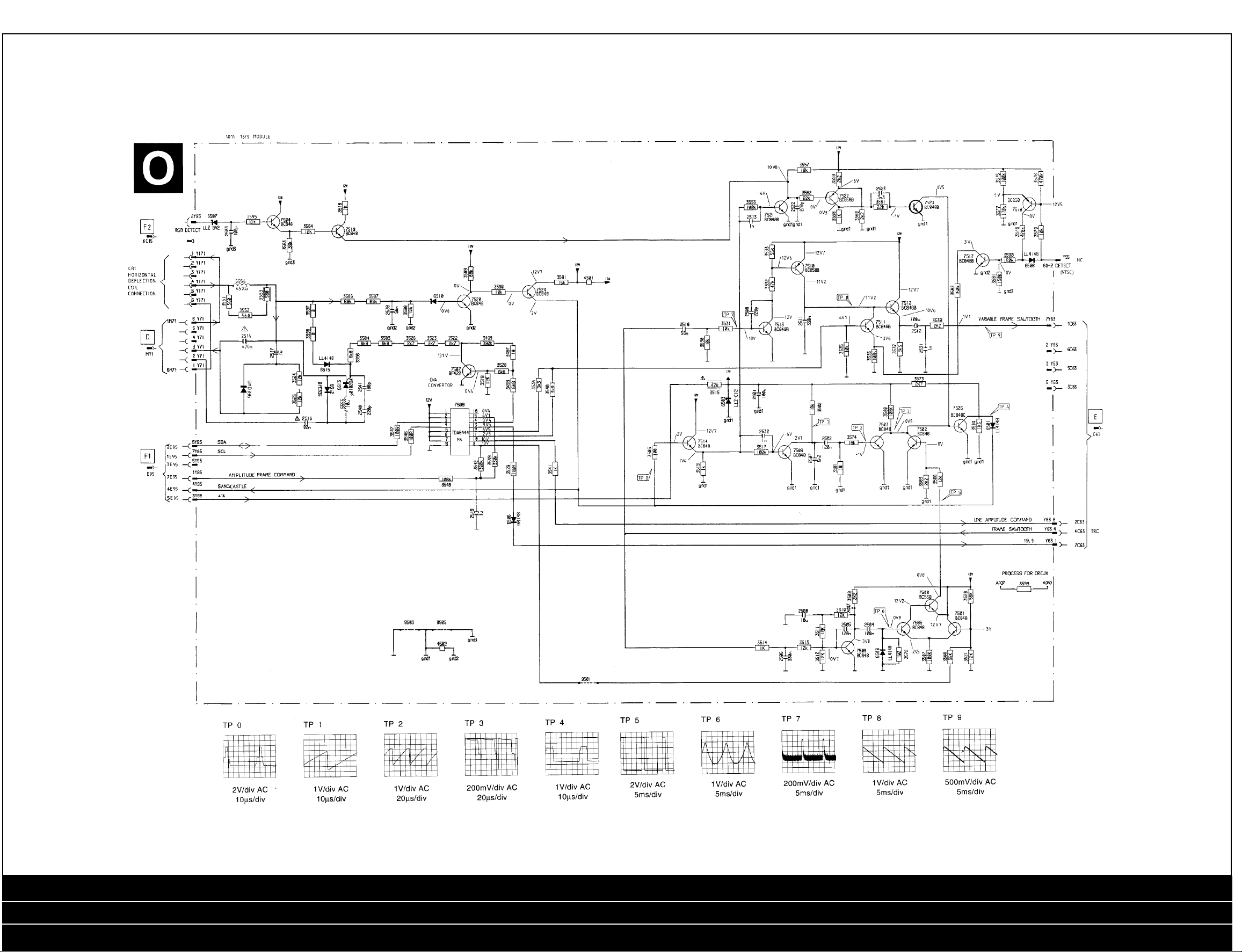
16:9 Module Diagram
16:9 Module / Comb Filter / Controls PCB / Directions for use / Electrical Adjustments ...Cont’d / Eurotext Module / Microprocessing Listing / Nicam BGL IF (J)
Nicam BGL IF (K) / Nicam Module (J) / Nicam Module (K) / Power Supply / Safety Parts / Scan Velocity Modulation / Scanning Module / SOPS Module / Video Processing
Stereo IF Module (L) / Stereo IF Module (M) / Testpoint Overview / Text (F1) / Text (F2) / Third Scart / Tube Base / Tube Base 16:9 / Tuner IF Audio Amp / Waveforms / Wiring Diagram
Page 5

5PHILIPS GR 2.4 Chassis
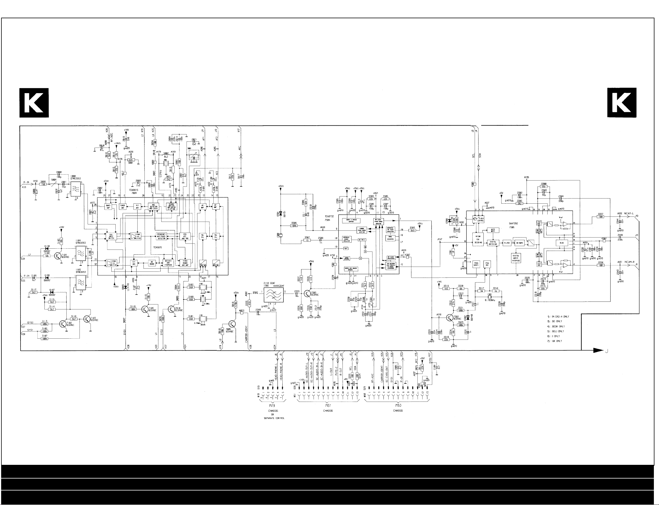
NICAM BGL IF (J) Diagram
16:9 Module / Comb Filter / Controls PCB / Directions for use / Electrical Adjustments ...Cont’d / Eurotext Module / Microprocessing Listing / Nicam BGL IF (J)
Nicam BGL IF (K) / Nicam Module (J) / Nicam Module (K) / Power Supply / Safety Parts / Scan Velocity Modulation / Scanning Module / SOPS Module / Video Processing
Stereo IF Module (L) / Stereo IF Module (M) / Testpoint Overview / Text (F1) / Text (F2) / Third Scart / Tube Base / Tube Base 16:9 / Tuner IF Audio Amp / Waveforms / Wiring Diagram
Page 6
PHILIPS GR 2.4 Chassis
6
NICAM BGL IF (K) Diagram
16:9 Module / Comb Filter / Controls PCB / Directions for use / Electrical Adjustments ...Cont’d / Eurotext Module / Microprocessing Listing / Nicam BGL IF (J)
Nicam BGL IF (K) / Nicam Module (J) / Nicam Module (K) / Power Supply / Safety Parts / Scan Velocity Modulation / Scanning Module / SOPS Module / Video Processing
Stereo IF Module (L) / Stereo IF Module (M) / Testpoint Overview / Text (F1) / Text (F2) / Third Scart / Tube Base / Tube Base 16:9 / Tuner IF Audio Amp / Waveforms / Wiring Diagram
Page 7

7PHILIPS GR 2.4 Chassis
Nicam Module (K)
Diagram
16:9 Module / Comb Filter / Controls PCB / Directions for use / Electrical Adjustments ...Cont’d / Eurotext Module / Microprocessing Listing / Nicam BGL IF (J)
Nicam BGL IF (K) / Nicam Module (J) / Nicam Module (K) / Power Supply / Safety Parts / Scan Velocity Modulation / Scanning Module / SOPS Module / Video Processing
Stereo IF Module (L) / Stereo IF Module (M) / Testpoint Overview / Text (F1) / Text (F2) / Third Scart / Tube Base / Tube Base 16:9 / Tuner IF Audio Amp / Waveforms / Wiring Diagram
Page 8

PHILIPS GR 2.4 Chassis
8
Power Supply Diagram
16:9 Module / Comb Filter / Controls PCB / Directions for use / Electrical Adjustments ...Cont’d / Eurotext Module / Microprocessing Listing / Nicam BGL IF (J)
Nicam BGL IF (K) / Nicam Module (J) / Nicam Module (K) / Power Supply / Safety Parts / Scan Velocity Modulation / Scanning Module / SOPS Module / Video Processing
Stereo IF Module (L) / Stereo IF Module (M) / Testpoint Overview / Text (F1) / Text (F2) / Third Scart / Tube Base / Tube Base 16:9 / Tuner IF Audio Amp / Waveforms / Wiring Diagram
Page 9

9PHILIPS GR 2.4 Chassis
Eurotext Module (F1) Diagram
16:9 Module / Comb Filter / Controls PCB / Directions for use / Electrical Adjustments ...Cont’d / Eurotext Module / Microprocessing Listing / Nicam BGL IF (J)
Nicam BGL IF (K) / Nicam Module (J) / Nicam Module (K) / Power Supply / Safety Parts / Scan Velocity Modulation / Scanning Module / SOPS Module / Video Processing
Stereo IF Module (L) / Stereo IF Module (M) / Testpoint Overview / Text (F1) / Text (F2) / Third Scart / Tube Base / Tube Base 16:9 / Tuner IF Audio Amp / Waveforms / Wiring Diagram
Page 10

PHILIPS GR 2.4 Chassis
10
Text (F1) Diagram
16:9 Module / Comb Filter / Controls PCB / Directions for use / Electrical Adjustments ...Cont’d / Eurotext Module / Microprocessing Listing / Nicam BGL IF (J)
Nicam BGL IF (K) / Nicam Module (J) / Nicam Module (K) / Power Supply / Safety Parts / Scan Velocity Modulation / Scanning Module / SOPS Module / Video Processing
Stereo IF Module (L) / Stereo IF Module (M) / Testpoint Overview / Text (F1) / Text (F2) / Third Scart / Tube Base / Tube Base 16:9 / Tuner IF Audio Amp / Waveforms / Wiring Diagram
Page 11

11PHILIPS GR 2.4 Chassis
Text (F2)
Diagram
SOPS Module Diagram
16:9 Module / Comb Filter / Controls PCB / Directions for use / Electrical Adjustments ...Cont’d / Eurotext Module / Microprocessing Listing / Nicam BGL IF (J)
Nicam BGL IF (K) / Nicam Module (J) / Nicam Module (K) / Power Supply / Safety Parts / Scan Velocity Modulation / Scanning Module / SOPS Module / Video Processing
Stereo IF Module (L) / Stereo IF Module (M) / Testpoint Overview / Text (F1) / Text (F2) / Third Scart / Tube Base / Tube Base 16:9 / Tuner IF Audio Amp / Waveforms / Wiring Diagram
Page 12

PHILIPS GR 2.4 Chassis
12
Third Scart Diagram
Wiring Diagram
Scan Velocity Modulation Module Diagram
Scanning
Module
Diagram
16:9 Module / Comb Filter / Controls PCB / Directions for use / Electrical Adjustments ...Cont’d / Eurotext Module / Microprocessing Listing / Nicam BGL IF (J)
Nicam BGL IF (K) / Nicam Module (J) / Nicam Module (K) / Power Supply / Safety Parts / Scan Velocity Modulation / Scanning Module / SOPS Module / Video Processing
Stereo IF Module (L) / Stereo IF Module (M) / Testpoint Overview / Text (F1) / Text (F2) / Third Scart / Tube Base / Tube Base 16:9 / Tuner IF Audio Amp / Waveforms / Wiring Diagram
Page 13

13PHILIPS GR 2.4 Chassis
Controls PCB Diagram
16:9 Module / Comb Filter / Controls PCB / Directions for use / Electrical Adjustments ...Cont’d / Eurotext Module / Microprocessing Listing / Nicam BGL IF (J)
Nicam BGL IF (K) / Nicam Module (J) / Nicam Module (K) / Power Supply / Safety Parts / Scan Velocity Modulation / Scanning Module / SOPS Module / Video Processing
Stereo IF Module (L) / Stereo IF Module (M) / Testpoint Overview / Text (F1) / Text (F2) / Third Scart / Tube Base / Tube Base 16:9 / Tuner IF Audio Amp / Waveforms / Wiring Diagram
Page 14

PHILIPS GR 2.4 Chassis
14
Comb Filter Diagram
16:9 Module / Comb Filter / Controls PCB / Directions for use / Electrical Adjustments ...Cont’d / Eurotext Module / Microprocessing Listing / Nicam BGL IF (J)
Nicam BGL IF (K) / Nicam Module (J) / Nicam Module (K) / Power Supply / Safety Parts / Scan Velocity Modulation / Scanning Module / SOPS Module / Video Processing
Stereo IF Module (L) / Stereo IF Module (M) / Testpoint Overview / Text (F1) / Text (F2) / Third Scart / Tube Base / Tube Base 16:9 / Tuner IF Audio Amp / Waveforms / Wiring Diagram
Page 15

15PHILIPS GR 2.4 Chassis
Video Processing Diagram
16:9 Module / Comb Filter / Controls PCB / Directions for use / Electrical Adjustments ...Cont’d / Eurotext Module / Microprocessing Listing / Nicam BGL IF (J)
Nicam BGL IF (K) / Nicam Module (J) / Nicam Module (K) / Power Supply / Safety Parts / Scan Velocity Modulation / Scanning Module / SOPS Module / Video Processing
Stereo IF Module (L) / Stereo IF Module (M) / Testpoint Overview / Text (F1) / Text (F2) / Third Scart / Tube Base / Tube Base 16:9 / Tuner IF Audio Amp / Waveforms / Wiring Diagram
Page 16

PHILIPS GR 2.4 Chassis
16
Stereo IF Module (L) Diagram
16:9 Module / Comb Filter / Controls PCB / Directions for use / Electrical Adjustments ...Cont’d / Eurotext Module / Microprocessing Listing / Nicam BGL IF (J)
Nicam BGL IF (K) / Nicam Module (J) / Nicam Module (K) / Power Supply / Safety Parts / Scan Velocity Modulation / Scanning Module / SOPS Module / Video Processing
Stereo IF Module (L) / Stereo IF Module (M) / Testpoint Overview / Text (F1) / Text (F2) / Third Scart / Tube Base / Tube Base 16:9 / Tuner IF Audio Amp / Waveforms / Wiring Diagram
Page 17

17PHILIPS GR 2.4 Chassis
Stereo IF Module (M) Diagram
16:9 Module / Comb Filter / Controls PCB / Directions for use / Electrical Adjustments ...Cont’d / Eurotext Module / Microprocessing Listing / Nicam BGL IF (J)
Nicam BGL IF (K) / Nicam Module (J) / Nicam Module (K) / Power Supply / Safety Parts / Scan Velocity Modulation / Scanning Module / SOPS Module / Video Processing
Stereo IF Module (L) / Stereo IF Module (M) / Testpoint Overview / Text (F1) / Text (F2) / Third Scart / Tube Base / Tube Base 16:9 / Tuner IF Audio Amp / Waveforms / Wiring Diagram
Page 18

PHILIPS GR 2.4 Chassis
18
Tuner IF Audio Amp Diagram
16:9 Module / Comb Filter / Controls PCB / Directions for use / Electrical Adjustments ...Cont’d / Eurotext Module / Microprocessing Listing / Nicam BGL IF (J)
Nicam BGL IF (K) / Nicam Module (J) / Nicam Module (K) / Power Supply / Safety Parts / Scan Velocity Modulation / Scanning Module / SOPS Module / Video Processing
Stereo IF Module (L) / Stereo IF Module (M) / Testpoint Overview / Text (F1) / Text (F2) / Third Scart / Tube Base / Tube Base 16:9 / Tuner IF Audio Amp / Waveforms / Wiring Diagram
Page 19

19PHILIPS GR 2.4 Chassis
Tube Base PCB Diagram
16:9 Module / Comb Filter / Controls PCB / Directions for use / Electrical Adjustments ...Cont’d / Eurotext Module / Microprocessing Listing / Nicam BGL IF (J)
Nicam BGL IF (K) / Nicam Module (J) / Nicam Module (K) / Power Supply / Safety Parts / Scan Velocity Modulation / Scanning Module / SOPS Module / Video Processing
Stereo IF Module (L) / Stereo IF Module (M) / Testpoint Overview / Text (F1) / Text (F2) / Third Scart / Tube Base / Tube Base 16:9 / Tuner IF Audio Amp / Waveforms / Wiring Diagram
Page 20

PHILIPS GR 2.4 Chassis
20
Tube Base PCB 16:9 Diagram
16:9 Module / Comb Filter / Controls PCB / Directions for use / Electrical Adjustments ...Cont’d / Eurotext Module / Microprocessing Listing / Nicam BGL IF (J)
Nicam BGL IF (K) / Nicam Module (J) / Nicam Module (K) / Power Supply / Safety Parts / Scan Velocity Modulation / Scanning Module / SOPS Module / Video Processing
Stereo IF Module (L) / Stereo IF Module (M) / Testpoint Overview / Text (F1) / Text (F2) / Third Scart / Tube Base / Tube Base 16:9 / Tuner IF Audio Amp / Waveforms / Wiring Diagram
 Loading...