

Philips FWR-33 Service Manual

For servicing the FW-R33 and FW-R55 the set has to be divided into two parts:
1. Except for the CD-R/W module all workshops can repair the set on component level.
2. The CD-R/W module can only be repaired on component level with the help of ComPair.
With this tool diagnosing of the set can be done in an interactive way. In the tool also the adjustment procedure has been
implemented. The adjustment is absolutely necessary in case the CDR Main Board and/or CD drive (CDR Loader) is
disconnected from the matched production combination.
Only designated workshops can perform these repairs!
Please send the complete set to the designated workshop.
Available circuit descriptions: The Basics of Compact Disc Recordable/Rewritable 4822 725 25242
3rd generation Compact Disc Recording 3104 125 40100
(with reference to description of the Basic Engine)
2nd line Service Manual CDR Mozart Module 3122 785 60030
Technical specification . . . . . . . . . . . . . . . . . . . . . . . . . . . 1-2
Measurement setup . . . . . . . . . . . . . . . . . . . . . . . . . . . . . 2-1
RC-5 codes. . . . . . . . . . . . . . . . . . . . . . . . . . . . . . . . . . . . 2-2
Warnings & Safety . . . . . . . . . . . . . . . . . . . . . . . . . . . . . . 2-3
Service Testprogram . . . . . . . . . . . . . . . . . . . . . . . . . . . . 3-3
Service Hints . . . . . . . . . . . . . . . . . . . . . . . . . . . . . . . . . . 3-1
Location of printed circuit boards . . . . . . . . . . . . . . . . . . . 3-2
Dismantling Instructions . . . . . . . . . . . . . . . . . . . . . . . . . . 3-3
Service Testprogram . . . . . . . . . . . . . . . . . . . . . . . . . . . 3-14
Wiring Diagram. . . . . . . . . . . . . . . . . . . . . . . . . . . . . . . . . 4-1
Blockdiagram . . . . . . . . . . . . . . . . . . . . . . . . . . . . . . . . . . 5-1
Front Board . . . . . . . . . . . . . . . . . . . . . . . . . . . . . . . . . . . . 6
MICROPHONE BOARD
. . . . . . . . . . . . . . . . . . . . . . . . . . . . . . . . . . 6-2
HEADPHONE BOARD
. . . . . . . . . . . . . . . . . . . . . . . . . . . . . . . . . . . 6-9
DIGITAL IN BOARD
. . . . . . . . . . . . . . . . . . . . . . . . . . . . . . . . . . . . 6-9
CDR LIGHTGUIDE
. . . . . . . . . . . . . . . . . . . . . . . . . . . . . . . . . . . . 6-9
3CDC-KEY BOARD
. . . . . . . . . . . . . . . . . . . . . . . . . . . . . . . . . . . 6-9
Tuner Board . . . . . . . . . . . . . . . . . . . . . . . . . . . . . . . . . . . . 7
Audio Frequency Board (AF9) . . . . . . . . . . . . . . . . . . . . . 8
Power Board. . . . . . . . . . . . . . . . . . . . . . . . . . . . . . . . . . . . 9
3 Disc Changer Module. . . . . . . . . . . . . . . . . . . . . . . . . . 10
CD R/W Module . . . . . . . . . . . . . . . . . . . . . . . . . . . . . . . . 11
Exploded view of set . . . . . . . . . . . . . . . . . . . . . . . . . . . . . 12
Partslist of set . . . . . . . . . . . . . . . . . . . . . . . . . . . . . . . . . . 12
FW-R33/37
Published by HB 0138 Service Audio Printed in The Netherlands Subject to modification
© 3103 785 25110
CDR Mini System
CLASS 1
LASER PRODUCT
©
Copyright 2001 Philips Consumer Electronics B.V. Eindhoven, The Netherlands
All rights reserved. No part of this publication may be reproduced, stored in a retrieval
system or transmitted, in any form or by any means, electronic, mechanical, photocopying,
or otherwise without the prior permission of Philips.
SERVICING
Table of Contents
FW-R55/21/22/37

1-2
General:
Mains voltage : 120 / 240V switchable (for /21)
: 230V (for /22)
: 120V (for /37)
Mains frequency : 50 ~ 60Hz
Power consumption : 85W at 1/8 P
RATED
: 350W at max output
: ≤15W at Stand by
: ≤2W at ECO Stand by
Tuner:
FM
Tuning range : 87.5MHz - 108MHz
Grid : 100kHz
IF : 10.7MHz
Aerial input : 75Ω
Sensitivity Mono (26dB S/N) : < 22dBf (typ. 16dBf)
d (RF=1mV,∆f=75kHz) : < 3% (typ. 1%)
IF rejection : > 60dB
Image rejection : > 25dB
-3dB Limiting Point : < 23.5dBf (typ. 15dBf)
MW
Tuning range : 531kHz - 1062kHz
Grid : 9kHz
IF : 450kHz ±1kHz
Sensitivity at 26dB S/N : < 4400µV/m
d (RF=50mV,m=80%) : < 5% - typ. 3%
IF rejection : > 45dB
Image rejection : > 28dB
Amplifier:
Output power : 2 x 55W at 6Ω
Headphone : 3.5mm stereo jack
Frequency response : 20Hz - 20kHz (-3dB) Limit
Equalizer : Digital Sound Control
Input sensitivity
Aux/Line : 500mV ±2dB
Microphone : 2.5mV ±2dB at 1kHz
CDC unit:
Frequency response within : 20Hz - 20kHz at ±1.5dB
Signal/Noise ratio : > 88dB (A-weighted)
Distortion at 1kHz,0dB : -80dB
Channel unbalance : < 0.3dB
Channel crosstalk at 1kHz : -75dB
De-emphasis : 0 or 15/50 µS
Laser
Output power : ≤500µW
Wave length : 780nm ±20nm
CDR unit:
CD Playback:
Frequency response within : 20Hz - 20kHz at ±1.5dB
Signal/Noise ratio : > 88dB (A-weighted)
Distortion at 1kHz,0dB : -80dB
Channel unbalance : < 1dB
Channel crosstalk at 1kHz : -75dB
De-emphasis : 0 or 15/50 µS
Analog recording - digital playback:
Frequency response within : 20Hz - 20kHz at ±1.5dB
Signal/Noise ratio : > 81dB (A-weighted)
Distortion at 1kHz,0dB : -78dB
Channel unbalance : < 1dB
Channel crosstalk at 1kHz : -65dB
De-emphasis : 0 or 15/50 µS
Laser
Output power : ≤1mW during reading
: ≤20mW during writing
Laser class 3B
Wave length : 780nm ±20nm
Technical Specification

2-1
Measurement Setup
Bandpass
250Hz-15kHz
e g. 7122 707 48001
LF Voltmeter
e.g. PM2534
DUT
RF Generator
e.g. PM5326
S/N and distortion meter
e.g. Sound Technology ST1700B
Use a bandpass filter to eliminate hum (50Hz, 100Hz) and disturbance from the pilottone (19kHz, 38kHz).
Ri=50Ω
Tuner FM
Bandpass
250Hz-15kHz
e.g. 7122 707 48001
LF Voltmeter
e g. PM2534
DUT
S/N and distortion meter
e.g. Sound Technology ST1700B
Frame aerial
e g. 7122 707 89001
Tuner AM (MW,LW)
To avoid atmospheric interference all AM-measurements have to be carried out in a Faraday´s cage.
RF Generator
e.g. PM5326
Ri=50Ω
Low pass filter 22kHz
L
R
LEVEL METER
e.g. Sennheiser UPM550
with FF-filter
S/N and distortion meter
e.g. Sound Technology ST1700B
DUT
CD
Use Audio Signal Disc SBC429 4822 397 30184 (replaces test disc 3)
L.P.F. = 13
th
order filter 4822 395 30204

2-2
RC5 Codes
Remote control key
SLEEP
DIM
REPEAT
SHUFFLE
TRACK INCREMENT
VOLUME +
VOLUME -
3
8
w
∑
1
CD, CDR MODE
1 AUX, TUNER MODE
¡ CD, CDR MODE
¡ AUX, TUNER MODE
7
INCREDIBLE SURROUND
PURE
LOUDNESS
BALANCE L
BALANCE R
WOOX
WOOX LEVEL
System Code
16
16
20, 26
20, 26
26
16
16
20, 26
20, 26
17,20, 21, 26
17,20, 21, 26
20, 26
17, 21
20, 26
17, 21
20, 26
16
16
16
16
16
16
16
Command Code
38
71
29
28
114
16
17
53
48
33
32
50
31
52
30
54
64
52
50
27
26
70
118
Remote control key
Standby
CD1
CD2
CD3
CDR
Tuner
Aux
1 (ABC)
2 (DEF)
3 (GHI)
4 (JKL)
5 (MN)
6 (OPQ)
7 (RST)
8 (UVW)
9 (XYZ)
0 (Space)
YES
NO
EDIT (TEXT)
PROGRAM
PROGRAM
TUNER MODE
MUTE
TIMER ON/OFF
System Code
17, 20, 21, 26
20
20
20
26
17
21
17,20, 21, 26
17,20, 21, 26
17,20, 21, 26
17,20, 21, 26
17,20, 21, 26
17,20, 21, 26
17,20, 21, 26
17,20, 21, 26
17,20, 21, 26
17,20, 21, 26
17,20, 21, 26
17,20, 21, 26
17,20, 21, 26
20, 26
17
16
16
Command Code
12
55
56
57
63
63
63
01
02
03
04
05
06
07
08
09
00
87
49
82
36
122
13
89
2-3
© WARNING
All ICs and many other semiconductors are susceptible to
electrostatic discharges (ESD). Careless handling during
repair can reduce life drastically.
When repairing, make sure that you are connected with the
same potential as the mass of the set via a wristband with
resistance. Keep components and tools at this potential.
f ATTENTION
Tous les IC et beaucoup d´autres semi-conducteurs sont
sensibles aux décharges statiques (ESD). Leur longévite
pourrait être considérablement écourtée par le fait qu´aucune
précaution nést prise à leur manipulation.
Lors de réparations, s´assurer de bien être relié au même
potentiel que la masse de l´appareil et enfileer le bracelet
serti d´une résistance de sécurité.
Veiller à ce que les composants ainsi que les outils que l´on
utilise soient également à ce potentiel.
d WARNUNG
Alle ICs und viele andere Halbleiter sind empfindlich
gegenüber elektrostatischen Entladungen (ESD).
Unsorgfältige Behandlung im Reparaturfall kann die
Lebensdauer drastisch reduzieren.
Sorgen Sie dafür, daß Sie im Reparaturfall über ein Pulsarmband mit Widerstand mit dem Massepotential des
Gerätes verbunden sind.
Halten Sie Bauteile und Hilfsmittel ebenfalls auf diesem
Potential.
ñ WAARSCHUWING
Alle IC´s en vele andere halfgeleiders zijn gevoelig voor
electrostatische ontladingen (ESD).
Onzorgvuldig behandelen tijdens reparatie kan de levensduur
drastisch doen vermindern. Zorg ervoor dat u tijdens reparatie
via een polsband met weerstand verbonden bent met hetzelfde
potentiaal als de massa van het apparaat.
Houd componenten en hulpmiddelen ook op ditzelfde potentiaal.
i AVVERTIMENTO
Tutti IC e parecchi semi-conduttori sono sensibili alle scariche
statiche (ESD).
La loro longevità potrebbe essere fortemente ridatta in caso di
non osservazione della più grande cauzione alla loro
manipolazione. Durante le riparationi occorre quindi essere
collegato allo stesso potenziale che quello della massa
delápparecchio tramite un braccialetto a resistenza.
Assicurarsi che i componenti e anche gli utensili con quali si
lavora siano anche a questo potenziale.
©
Safety regulations require that the set be restored to its
original condition and that parts which are identical with
those specified be used.
Safety components are marked by the symbol
i
Le norme di sicurezza estigono che l´apparecchio venga
rimesso nelle condizioni originali e che siano utilizzati i
pezzi di ricambiago identici a quelli specificati.
Componenty di sicurezza sono marcati con
ñ
Veiligheidsbepalingen vereisen, dat het apparaat in zijn
oorspronkeliijke toestand wordt teruggebracht en dat
onderdelen, identiek aan de gespecificeerde, worden toegepast.
De Veiligheidsonderdelen zijn aangeduid met het symbool
s Varning !
Osynlig laserstrålning när apparaten är öppnad och
spärren är urkopplad. Betrakta ej strålen.
∂ Advarsel !
Usynlig laserstråling ved åbning når sikkerhedsafbrydere
er ude af funktion. Undgå udsaettelse for stråling.
ß Varoitus !
Avatussa laitteessa ja suojalukituksen ohitettaessa olet alttiina
näkymättömälle laserisäteilylle. Älä katso säteeseen !
f
"Pour votre sécurite, ces documents doivent être utilisés par
des spécialistes agréés, seuls habilités à réparer votre
appareil en panne".
ESD
SAFETY
d
Bei jeder Reparatur sind die geltenden Sicherheitsvorschriften zu beachten. Der Originalzustand des Gerätes
darf nicht verändert werden. Für Reparaturen sind Originalersatzteile zu verwenden.
Sicherheitsbauteile sind durch das Symbol markiert.
f
Les normes de sécurité exigent que l`appareil soit remis
à l`état d`origine et que soient utilisées les pièces de
rechange identiques à celles spécifiées.
Les composants de sécurité sont marqués
CLASS 1
LASER PRODUCT
©
DANGER: Invisible laser radiation when open.
©
After servicing and before returning the set to customer
perform a leakage current measurement test from all
exposed metal parts to earth ground, to assure no
shock hazard exists.
The leakage current must not exceed 0.5mA.
AVOID D RECT EXPOSURE TO BEAM.
©
AVAILABLE ESD PROTECTION EQUIPMENT :
anti-static table mat large 1200x650x1 25mm 4822 466 10953
small 600x650x1.25mm 4822 466 10958
anti-static wristband 4822 395 10223
connection box (3 press stud connections, 1MΩ) 4822 320 11307
extendible cable (2m, 2MΩ, to connect wristband to connection box) 4822 320 11305
connecting cable (3m, 2MΩ, to connect table mat to connection box) 4822 320 11306
earth cable (1MΩ, to connect any product to mat or to connection box) 4822 320 11308
KIT ESD3 (combining all 6 prior products - small table mat) 4822 310 10671
wristband tester 4822 344 13999
Warnings & Safety
3-1
TORX T10 screwdriver with shaftlength 150mm ......................................4822 395 50423
TORX screwdriver set SBC 163..............................................................4822 295 50145
Audio signal disc SBC 429......................................................................4822 397 30184
Playability test disc SBC444...................................................................4822 397 30245
Test disc 5 (disc without errors) +
Test disc 5A (disc with dropout errors, black spots and fingerprints)
SBC 426/426A ....................................................................4822 397 30096
Burn in test disc (65 min. 1kHz signal at -30dB level without "pause")...4822 397 30155
Service Tools
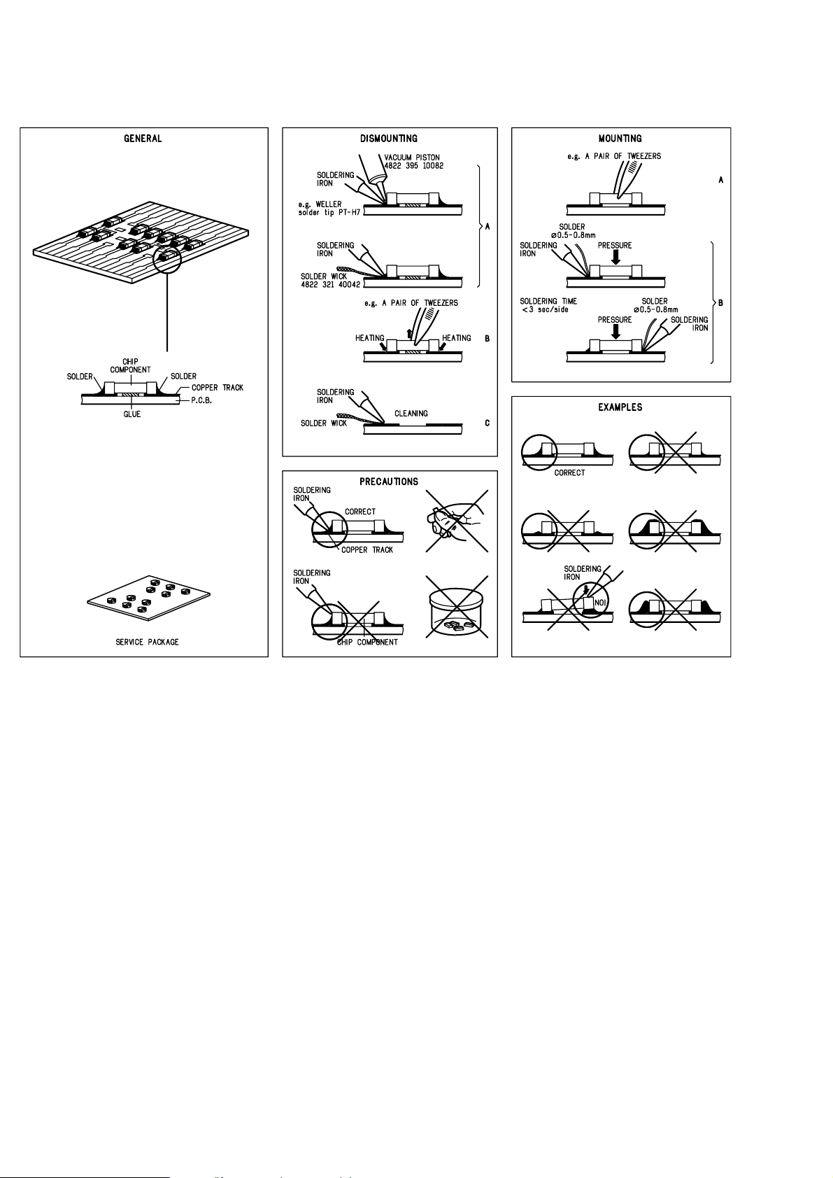
Service hints
Handling chip components
The sets are equipped with a special DEALER MODE.
This mode blocks the trays of the CDC - and CDR module to prevent customers from fetching out CDs from exhibition sets.
The dealer mode can be switched on/off as follows:
1) Switch the set with the stanby-button to standby mode
2) Press the [DISPLAY] key for longer than 5s
→ Display shows „ TRAYS LOCKED“ respectively „ UNLOCKED“
Escape from „Dealer Mode“
The demo mode displays various features of the set and will start automatically.
To cancel the demo mode keep „STOP“ button on the set pressed for at least 5 seconds.
The demo mode is cancelled permanently. The set switches to standby.
Escape from „Demo Mode“
3-2
DISPLAY FRONT
JOG FRONT
Headphone
Tuner
Digital In
Board
Microphone
Power Module
Combi Board
Power Module
Mains Board
AF9 Board
3CDC Keys
CDR Lightguide
FW-R55 Locationof Printed Circuit Boards 2001 04 12
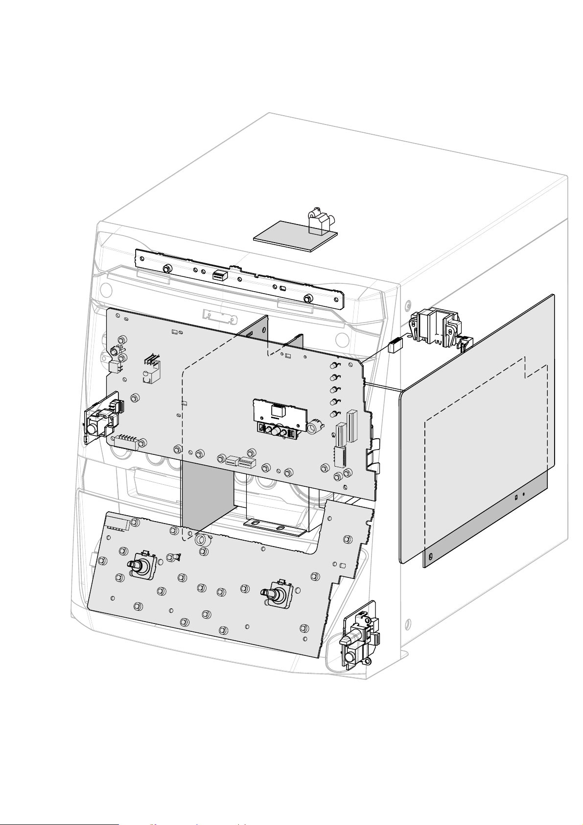
Location of Printed Circuit Boards
Attention:
CDR Lightguide, 3CDC-Key Board, Digital In Board, Microphone Board and Headphone Board are part of the Front Board.

3-3
picture 1
DISMANTLING INSTRUCTIONS
Dismantling the
Top Cover
• Remove 4 screws as shown in picture 1.
• Raise top cover at the rear and pull it backwards as shown in picture 2.
picture 2

3-4
picture 3
picture 4
DISMANTLING INSTRUCTIONS
Dismantling the
Side Cover
• Remove 3 screws (for each side) as shown in picture 3.
• Remove side cover as shown in picture 4.

3-5
DISMANTLING INSTRUCTIONS
Dismantling the
3CDC Module
In case of a Supply fault, the tray can be opened manually.
• Turn gearwheel clockwise (as shown in picture below).
Remove the 3CDC Tray cover
• To release the cover from the catch on the tray pull it
frontwards on bottom side as shown in picture 5.
• Pull the cover up.
picture 5

3-6
picture 7
picture 6
Dismantling the
3CDC Module
(continued)
• Remove 2 screws on front side first → see picture 6.
• Remove 2 screws on back side →see picture 7.
DISMANTLING INSTRUCTIONS

3-7
DISMANTLING INSTRUCTIONS
Repair position for the
3CDC Module

3-8
DISMANTLING INSTRUCTIONS
Dismantling the
CDR Module
• Remove 3CDC module first. see previous pages
• Remove CDR Tray cover → see picture 8.
In case of a Supply fault, the tray can be opened manually.
• Use a screwdriver to release the tray (as shown in picture below).
picture 8

3-9
DISMANTLING INSTRUCTIONS
Dismantling the
CDR Module
(continued)
• Remove 2 screws on front side first →see picture 9.
• Remove screws on the left and the right side → see picture 10.
picture 9
picture 10
3-10
DISMANTLING INSTRUCTIONS
Dismantling the
CDR Module
(continued)
• Disconnect all wires and remove the module.
• Loosen screws shown in picture 11 and remove the top cover.
picture 11
Repair position for the
Mozart Module
• Connect Power, Front, AF9 Board and 3CDC Module to get an
operating CDR Module
Power supply
Front Board
3CDC Module
AF9 Board

3-11
DISMANTLING INSTRUCTIONS
Dismantling the
CDR Module - Mozart Board
(continued)
• Remove 2 screws as shown in picture 12 to get access to the
other side or to dismantle the Mozart Board.
Repairs on Basic Engine
• Remove Mozart Board as described before.
• Open the tray.
• Remove 4 screws as shown in picture 13 to dismantle the module from the metal box.
This is necessary to get access to the Basic Engine.
picture 12
picture 13

3-12
Repair position for the CDR Module -
Basic Engine
• Connect Power, Front, AF9 Board and 3CDC Module to get an
operating CDR Module
DISMANTLING INSTRUCTIONS
3-13
Dismantling the
Audio Frequency Board
• Remove 3CDC module first. see chapter 3-5 to 3-7
• Release two catches → see picture 14.
• Remove 3 screws → see picture 14.
DISMANTLING INSTRUCTIONS
Repair position for the
Power Board
• Place the AF9 board on the CDR Module as shown in picture below.
! Use a sheet of cardboard inbetween to avoid shortcircuits!
picture 14

3-143-14
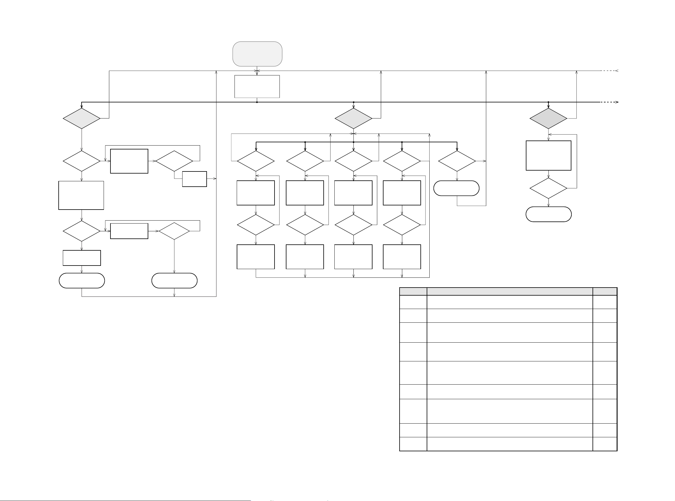
*
To leave Service Testprogram plug mains cord off.
FW-R55 Service Testprogram Main 2001 06 12
Display shows
version number
of the µP - software.
To enter Service
Testprogram hold
PLAY & CD3
buttons
depressed while
plugging mainscord in.
SERVICE TESTPROGRAM
MAIN
stands for Service mode on FW-R33
stands for version number
of the software used in the
Front µP.
S-FWR55-VXX
VXX
S-FWR33
stands for Service mode on FW-R55
S-FWR55
NTC XXXX
N
Y
TEMPERATURE TEST
Display shows
XXXX = value in mV
Source = AUX
AUX
button
pressed?
STOP
button
pressed?
N
Y
To check he temperature of he mains transformer under load.
Apply an audio signal to AUX.
Note:
Very first sets will display °C instead of a voltage value.
Millivolts are always displayed with 4 digits,
while °C are displayed with 2 or 3 digits.
Action
Software reduces output power
Software switches set in Stand by
Display
< 1670
< 1470
Temp.
>104°C
>128°C
N
Y
QUARTZ TEST
Display shows
512Hz can be measured
on pin 19 of Front-µP
N
Y
SEARCH 5
button
pressed?
SEARCH 5
button
pressed?
Tact frequency µP
(divided 32kHz)
32K
Display shows
1220Hz can be measured
on pin 19 of Front-µP
STOP
button
pressed?
N
Y
Tact frequency µP
(divided 10MHz)
10M
NEW
N
Y
EEPROM CLEAR
Display shows
for 2 second
Load default data !
CD TEXT
button
pressed?
PASS
N
Y
EEPROM TEST
Display shows
ERR
Display shows
Testpattern is written to
an address
and
read back again
PROGRAM
button
pressed?
STOP
button
pressed?
Test ok?
N
Y
N
Y
This test should only be used to clear
the EEPROM in case of a µP-"hangup".
Attention: all data are set to default values,
BLACK BOX data are not cleared.
DISPLAY
button
pressed?
DISPLAY
button
pressed?
N
N
Y
Fig. 1
Y
Display shows all
segments and flags
in dimmed mode
for checking open circuits.
see figure 1
All LEDs
except the blue ones
are switched on.
STOP
button
pressed?
N
Y
Display shows
segments and flags
as shown in Fig. 2
for checking short circuits.
All LEDs
except the blue ones
are switched off.
DISPLAY TEST
PMAMTRACKEDITCD TEXTPLAYLISTALBUMPRESET
STEP TOTAL TIME TIMETRACK REMTOTAL TRACKREC
Fig. 2
AMCD
TIMETRACK TOTAL REC
N
Y
KEY TEST
Display shows
Numbers acc. table 1
are indicated as long as a
button is held depressed.
If a button is pressed
on the Remote Control
KEY RC is shown
and the ; flag flashes.
FFWD 6
button
pressed?
STOP
button
pressed?
N
Y
KEY --
Set key
STOP
NO / CANCEL
1 SEARCH BKW
¡ SEARCH FWD
YES / ENTER
3 PLAY
REC LEVEL
CD TEXT / EDIT
COPY CD
COMPILE CD
7 RECORD
FINALIZE
ERASE
INCREDIBLE SURROUND
DSC
VAC
Code
exit Test
17
18
19
20
21
22
23
24
25
26
27
28
29
30
31
Set key
DISC CHANGE
OPEN / CLOSE CD
Stand By / ON
ECO POWER
DISPLAY / RDS
CDR
CD1
CD2
CD3
CLOCK / TIMER
TUNER
AUX
wOOx ON / OFF
wOOx LEVEL
for FW-R55 only
MAX SOUND for FW-R33 only
OPEN / CLOSE CDR
PROG
Code
0
1
2
3
4
5
6
7
8
9
10
11
12
13
13
14
15
Table 1
3-15 3-15
FW-R55 Service Testprogram 3CDC 2001 08 16
OPEN/CLOSE
button
pressed?
Y
NEXT
6
button
pressed?
N
Y
PREV
5
button
pressed?
N
Y
PLAY
button
pressed?
N
Y
CD or CDC
MECHANICAL TEST
SLIDE TESTFOCUS TEST TRAY TESTTURNTABLE
TEST
Display shows:
SLIDE
for visual inspection only
OPEN/CLOSE
button
pressed?
N
Y
Y
N
Y
N
Slide moves
continuously in/out.
Display shows:
OPEN
(even when tray is blocked)
Tray opens.
Display shows:
CLOSE
(even when tray is blocked)
Tray closes.
Dependent on the
moving direction,
slide moves to inner
or outer end position.
N
Y
STOP
button
pressed?
Exit Mech. Testprogram
Objective moves
continuously up/down.
Display shows:
FOCUS
PREV
5
button
pressed?
N
Y
YES
button
pressed?
N
Y
Turntable motor
is switched on.
Display shows:
DISC
PREV
5
button
pressed?
Focus servo
is switched off.
Turntable motor
is switched off.
N
Y
CD or CDC
LOADER TEST
TEST O K ?
NN
Y
Y
Display shows:
BERR 1
Display shows:
PASSED
for 3s
Tray opens
FFWD
6 button
pressed?
CD-DA disc
inserted?
Display shows actual
playing time.
The test is performed by
playing 5s at beginning,
5s in the middle and 5s at
the end of the disc.
N
Y
Display shows:
WRONG DISC
or
NO DISC
OPEN/CLOSE
button
pressed?
N
Y
CD1
button
pressed?
Exit CD electrical Test Exit CD electrical Test
set continues operation, message remains on the display until next error occurs
or any key is pressed.
Error number Error type
Error type:
Error description
E1000 Focus Error
Triggered when he focus is lost for more than 250ms while playing the CD.
E1006 Subcode Error
No valid subcode for 300ms during
PLAY
.
Slide-out error
Generated when he inner-switch did not open within approx. 250ms when the pick up is
moved from the inner position outside. Inner-switch or slide motor problems.
E1002
E1003
Slide-in error
Generated when he inner-switch did not close within approx. 6s when the pick up is
moved inside. Inner-switch or slide motor problems.
W
E1020 Focus Search Error
Triggered when he focus could not be found wi hin 4s when starting up the CD.
F
W
W
E1001 Radial error
Triggered when he radial servo is not on track for a certain time during playing the CD.
W
W
W
W
W = Warning →
F = Fatal Error
→ set stops operation, message remains on the display.
CD ERROR CODES
table 1
E1005 Jump error.
Triggered when the servo processor counts too less tracks in a defined time during JUMPS.
This can be caused by a disturbed HF-signal (the tracks cannot be recognized exactly),
slide motor problems, track servo problems or scratched discs.
E1008 Disc motor error
Generated when he CD could not reach 75% of speed during startup within 1,2s.
W
E1007 PLL lock error
When no valid subcode was found within 300ms PLL is checked. If PLL is locked E1006
will be indicated else E1007 and he servo is stopped and restarted once again to recover
(as if the user would have pressed
STOP
and then
PLAY
immediately).
The
CD PLAY TEST
is intended to be used
for continuously playing a disc in order to
detect intermittent or not reproducible
failures. The error code indicates where
the failure can be found.
2)
Y
CD PLAY TEST
2)
(CD BURN IN TEST)
N
CD is in normal
PLAY
mode.
In case of failures
error codes acc. table 1
will be indicated
on the display.
MAINS CORD
plugged off?
N
Y
Exit Service Testprogram
CD3
button
pressed?
switch to standby deleted
With the
DISPLAY
button the info on the
display can be toggled to indicate either
the status of
CD PLAY TEST
or
the temperature measured via the NTC.
3)
3)
stands for version number
of the software used in the
Front µP.
VXX
S-FWR33
S-FWR55
Display shows
version number
of the µP - software.
To enter Service
Testprogram hold
PLAY & CD3
buttons
depressed while
plugging mainscord in.
* To leave Service Testprogram
plug mains cord off.
S-FWR55-VXX
SERVICE TESTPROGRAM
3CDC MODULE
*
In the main menu the sound settings (volume, ...),
trays and carousel work as in normal mode.
CD2
button
pressed?
N
Y
Note:
These tests are not implemented in the first sets.

3-163-16
FW-R55 Service Testprogram CDR 2001 08 16
Note: These tests are not implemented in the first sets.
CDR
button
pressed?
TEST O K ?
NN
N
Y
Y
N
Y
Y
Y
Display shows for 5s
CDR
ELECTRICAL TEST
Insert CD-DA disc
before starting the test
MODULE
INFORMATION
MOZART BOARD DIAGNOSTIC
CDR - LOADER TEST
SDRAM TEST 7100
Display shows:
DTST1
CHECKSUM TEST 7701
Display shows:
DTST2
ERASE TEST 7701
Display shows:
DTST3
COMMUNICATION TEST
(DSA BUS)
Display shows:
DTST4
Display shows:
DERR
n
n=number of failed test
Display shows next error
FFWD
6 button
pressed?
N
Y
FFWD
6 button
pressed?
Y
FFWD
6 button
pressed?
Y
FFWD
6 button
pressed?
all errors shown?
N
N
N
FFWD
6 button
pressed?
Y
N
TEST O K ?
NN
Y
Y
Display shows:
BERR 1
FFWD
6 button
pressed?
CD-DA disc
inserted?
Display shows actual
playing time.
The test is performed by
playing 5s at beginning,
5s in the middle and 5s at
the end of the disc.
N
Y
Display shows:
NO DISC
FFWD
6 button
pressed?
Exit CDR electrical Test
Exit CDR electrical Test Exit CDR electrical Test
MXXXXX BXXXX
MXXXXX
Software version of
Mozart (flash ROM 7101)
BXXXX Software version of
basic engine processor (flash EPROM 7017)
OPEN/CLOSE
button
pressed?
FINALIZE
button
pressed?
N
Y
Y
NEXT
6
button
pressed?
N
Y
PREV
5
button
pressed?
N
Y
STOP
button
pressed?
N
Y
CDR
MECHANICAL TEST
SLIDE TEST TRAY TEST
Display shows:
BUSY
for visual inspection only
OPEN/CLOSE
button
pressed?
N
Y
Slide moves
continuously in/out.
Display shows:
OPENED
(even when tray is blocked)
Tray opens.
Display shows:
CLOSE
(even when tray is blocked)
Tray closes.
PLAY
button
pressed?
NN
Y
FOCUS TEST
PLAY
button
pressed?
N
Y
Dependent on the
moving direction,
slide moves to inner
or outer end position.
Exit Mech. Testprogram
YES
button
pressed?
N
Y
TURNTABLE
TEST
YES
button
pressed?
N
Y
Display shows:
DISC
Turntable motor
is switched on.
Turntable motor
is switched on.
Objective moves
continuously up/down.
Display shows:
FOCUS
Focus servo
is switched off.
stands for version number
of the software used in the
Front µP.
VXX
S-FWR33
S-FWR55
Display shows
version number
of the µP - software.
To enter Service
Testprogram hold
PLAY & CD3
buttons
depressed while
plugging mainscord in.
*
To leave Service Testprogram
plug mains cord off.
S-FWR55-VXX
SERVICE TESTPROGRAM
CDR MODULE
Note: The BURN-IN mode is an endless cycle of
*
DC erase, to erase he CD-RW disc with max. laser power
*
Recording a CD-RW disc with speed N=1
*
and Finalizing with double speed
This test is intended to check the quality of a CDR loader and
to detect intermittent failures.
With the
DISPLAY
button the info on the display can be toggled
to indicate ei her the status of burn in test or the temperature
measured via the NTC.
1)
CD-RW disc
inserted?
N
Y
STOP button
pressed?
Y
N
DC-ERASE
finished?
N
Y
BURN IN MODE
CDR MODULE
Display shows:
HH BI RE FE
DC-ERASE MODE
starts.
Record complete disc
from analog source
with normal speed.
Display shows:
WRONG DISC
or
NO DISC
Display shows:
HH BI RE FE
Complete disc
recorded?
N
Y
Error detected?
N
Y
Finalize disc
with double speed.
Display shows:
HH BI RE FE
HH stands for the number of hours
the test was running
BI stands for Burn In test
RE number of errors detected during
DC erase and write mode
FE number of errors detected during
Finalizing the disc
REC TYPE
button
pressed?
N
Y

3-17 3-17
Note:
These tests are not implemented in the first sets.
FW-R55 Service Testprogram CD Erase 2001 08 16
stands for version number
of the software used in the
Front µP.
VXX
S-FWR33
S-FWR55
Display shows
version number
of the µP - software.
To enter Service
Testprogram hold
PLAY & CD3
buttons
depressed while
plugging mainscord in.
*
To leave Service Testprogram
plug mains cord off.
S-FWR55-VXX
SERVICE TESTPROGRAM
CDR MODULE
N
Y
STOP button
pressed?
Y
N
Display shows:
WRONG DISC
or
NO DISC
Disc erased?
N
Y
N
Y
Complete disc will be
erased with double speed.
(starting from PMA-area
up to and including
ATIP leadout area)
The display shows the
countdown of the
remaining time required
to complete the opera ion:
ER mm ss
Display shows:
PASSED
mm: remaining minutes
ss: remaining seconds
STOP
button
pressed?
Exit DC-ERASE Mode
Note: With the DC-Erase mode the CD-RW can be
changed back in its original state, l ke a new disc.
Stopping the erase-function by switching power off
will leave the disc in an unpredictable status!
CD-RW disc
inserted?
ERASE
button
pressed?
N
Y
CDR
DC-ERASE MODE
Insert CD-DA disc
before starting the test
NY
Plug mains cord off
to exit
END-USER DIAGNOSTICS
Display shows:
FAILED
Display shows:
PASSED
END-USER DIAGNOSTICS
(CDR module)
To enter
END-USER DIAGNOSTICS
hold
PLAY & REC LEVEL
buttons depressed while
plugging mainscord in.
On/Off switch in pos.
ON
TEST O.K.?
Display shows for 3s each:
• Software version of
MOZART (flash ROM 7101)
• Software version of
basic engine processor
(flash EPROM 7017)
SDRAM TEST 7100
Display shows:
DTST1
CHECKSUM TEST 7101
Display shows:
DTST2
ERASE TEST 7101
Display shows:
DTST3
COMMUNICATION TEST
(UART-BUS)
Display shows:
DTST4
Flash Proms are set
to default settings.

4-14-1
AUX IN
LINE OUT
SUBWOOFER
Manis
SUPPLY (mains)
POWER-BOARD
2x30 & 70W
LS
DIG IN
TUNER
ECO 6
HEADPHONE
Audio Frequency Board
AF9
JOG-FRONT
FW-R55
DIG IN
CD-CHANGER
3CDC LC
CD-R/W
SBA-CDR01
DISPLAY-FRONT
FW-R55
HP
3p/340mm
8p/340mm
8p/140mm
4p/340mm
13p/280mm
6p/280mm
7p/280mm
7p/280mm
7p/280mm
1mm1mm
16p/220mm
11p/220mm
9p/220mm
6p/220mm
6p/220mm
12p/140mm
1203
1007
1205
1402
1214
1802
1532
1402
1603
1520
1204
1201
1306
1310
1312
1302
1203
1304
1209
1120
1204
LED
MICROPHONE
MIC
1510
5p/180mm
1222
1320
1226
1220
1600
1224
1225
1405
1803
1805
1525
1400
1700
8001
8002
8003
8014
8006
8004
Part of Changer
8007
8005
8008
8009
8013
8012
8011
8010
8018
KEY
4p/280mm
1221
1502
8017
8015
5p/180mm
1223
SDA
EBU
SICL
CD10_res.
GND_D
SILD
RAB
REC_Left
GND_A
REC_Right
GND_A
CDR_Right
GND_A
CDR_Left
F2
F1
SW_INFO
CD_SH_STR
CD_SH_DATA
NTC
GND_D
I2C Clock
I2C_Data
+5V6
+5V6
+5V6 con
-Vkk
GND_D
GND_D
F2
F1
SW_INFO
CD_STR
CD_DATA
NTC
GND_D
I2C Clock
I2C_Data
+5V6
+5V6
+5V6 con
-Vkk
GND_D
GND_D
CD_CLK
CD_SH_CLK
Power down
NC
Clip
Tu_Stereo
Tu_GND
Tu_CE
Tu_Data
HP_DET
Tu_Clk
Low power control
11V
GND_M
GND_D
5V
5V
GND_D
GND_D
CW_DATA
GND_D
CW_CLK
RESET
CIREQ
GND_D
IIC_data
GND_D
IIC_clock
RESET
CIREQ
GND_D
EBU_In
GND_D
NC
NC
GND_D
EBU_In
GND_D
MIC DET
LED3
+5V6
+5V6
LED1
KEY_1
GND_D
KEY_0
JOG_B
JOG_A
VOL_A
GND_D
VOL_B
GND_D
GND_D
LED4
+5V6
LED1
GND_D
JOG_B
JOG_A
VOL_A
GND_D
VOL_B
GND_D
KEY_1
KEY_0
+E
+E
GND_D
GND_D
GND_D
KEY_2
GND_D
LED3
+5V6
GND D
LED4
GND_D
F_TxD
F_CNV
RESET
GND_D
F_EPM
F_CE
F_RxD
F_CLK
F_RTS
+E
GND_D
AMP_left
GND_A
AMP_right
NTC
Low Power Control
POWER DOWN
Clipping
AMP ON
-Vkk
F1
F2
Ampl_CS_DC
VCD_ON/CDR_ON
Low Power supply
+12V_A
GND_A
+12V_M
GND_M
+5V6
GND_D
Power down
SA_IN
MIC DET
Clip
Tu_Stereo
Tu_GND
Tu_Enab
Tu_Data
HP_DET
Tu_Clk
Low power control
KEY_2
GND_D
GND_D
GND_D
AF_left
GND_A
AF_right
NTC
Low Power Control
POWER DOWN
Clipping
AMP ON
-Vkk
F1
F2
NC
VCD_ON/CDR_ON
Low Power supply
+12V_A
GND_A
+12V_D
GND_M
+5V6
GND_D
+12V_CDR
GND_M
GND_D
5V_VCD
5V_VCD
GND_D
-Vkk
F2
NTC
Low_Power_supply
ECO
F1
POWER_DOWN
-Vkk
NTC
Low_Power_supply
ECO
POWER_DOWN
A1
A1
GND_D
B1
C1
GND_D
GND_D
GND_D
Ac1
Ac2
GND_A
TU_CLK
TU_LEFT
TU_RIGHT
TU_DATA
TU_STEREO
TU_ENAB
+11V_A
HP_DET
HP_LEFT
GND_A
HP_RIGHT
HP_DET
HP_LEFT
GND_A
HP_RIGHT
GND_A
TU_CLK
TU_LEFT
TU_RIGHT
TU_DATA
TU_STEREO
TU_ENAB
+12V_A
REC_Left
GND_A
REC_Right
GND_A
CDR_Right
GND_A
CDR_Left
NC
CD_SH_DATA
CD_SH_CLK
CD_SH_STR
SW_INFO
+12V_A
GND_D
+5V_CD
NC
MIC_DET
+12V_A
MIC
GND_A
GND_A
NC
CD_SH_DATA
CD_SH_CLK
CD_SH_STR
SW_INFO
+10V
GND_D
+5V
SDA
EBU
GND_D
SICL
CD10_res.
GND_D
SILD
RAB
MIC_DET
+11V_A
MIC
GND_A
GND_A
F2
F1
A1
A1
B1
C1
NC
WIRING DIGRAM
Wiring D agram FW-R55 2001-0 -20
1
11
1
6
12
1
16
1
12
1
1
1
4
4
1
5
5
1
1
10
1
1
11
16
1
1
1
1
1
6
7
7
13
13
1
1
1
1
1
1
4
8
9
77
6
5
1
1
1
1
1
7
1
4
8
1
7
6
6
1
2
1
1
1
9
8
8
1
5
1
1
1
3
5
6

5-1 5-1
Block Diagram FW-R55 17 09 2001
I2C BUS
I2C BUS
TUNER CONTROL
INTERFACE
3CDC CONTROL
INTERFACE
1226
1
I
2
C DATA
I
2
C CLK
RESET
IRQ
Display
driver
Microprocessor
DISPLAY FRONT
for details see
Chapter 6
LED BOARD
for details see
Chapter 6
JOG FRONT
for details see
Chapter 6
1224
11
1
TU_CE
HP_DET
Not Connected
TU_Data
TU_Stereo
TU_CLK
MIC_DET
Low_Power_Control
PowerDown
Clip
1220
5
1
LED4
+5V6
1600
1
5
1225
1
16
I
2
C CLK
+5V6 con
+5V6
CD_STR
SW_INFO
I
2
C DATA
NTC
F2
CD_DATA
CD_CLK
F1
+5V6
-Vkk
7001
7002
1222
1
12
1320
12
1
VOL_B
JOG_B
+E
KEY_0
KEY_1
+5V6
LED1
JOG_A
VOL_A
VOL_B
JOG_B
+E
KEY_0
KEY_1
+5V6
LED1
JOG_A
VOL_A
LED3
LED4
+5V6
LED3
KEY BOARD
for details see
Chapter 6
1221
4
1
1502
1
4
KEY2
KEY2
+E
+5V6
+E
JOG A
JOG_B
YES
+E +E
VOL_A
VOL_B
VOL
JOG
+5V6 +5V6
RED BLUE
I2C BUS
HEADPHONE BOARD
for details see
Chapter 6
1700
1
4
HP_LEFT
HP_DET
HP_RIGHT
1400
1
5
MIC
MIC_DET
+11V_A
MICROPHONE BOARD
for details see
Chapter 6
1404
CDR CONTROL
INTERFACE
MIC
Headphone
POWER MODULE
(Amplifier part)
for details see
Chapter 9
POWER MODULE
(Supply part)
for details see
Chapter 9
CDR SUPPLY
1312
1
6
+5V_VCD
+5V_VCD
+12V_CDR
Super Class G Supply
1203
6
1
B1
C1
A1
A1
1302
6
1
B1
C1
A1
B1
C1
A1
A1
1209
7
1
NTC
ECO
-Vkk
F1
F2
PowerDown
1304
7
1
Low_Power_Supply
NTC
ECO
-Vkk
F1
F2
PowerDown
Low_Power_Supply
1310
7
1
+12V_D
+5V6
Low_Power_Supply
+12V_A
1209
13
1
NTC
Low_Power_Control
PowerDown
Clipping
AF_right
AF_left
F2
NC
CLASS G Switch
VCD/CDR_ON
F1
AMP ON
-Vkk
7301
7302
POWER
AMP
8
1
EBU IN CD10
AUDIO SIGNAL INTERFACE
DIGITAL IN
CONTROL INTERFACE
SUPPLY INTERFACE
CD INTERFACE
RESET CD10
CD10 SDA
CD10 SCL
CD10 RAB
CD10 SILD
CDR MODULE
for details see
Chapter 11
1532
1007
1203
1803
DIG IN
1205
17
1
1
5
I
2
C DATA
I
2
C CLK
RESET
EBU IN
not connected
not connected
ANALOG IN (REC) L
ANALOG IN (REC) R
ANALOG OUT (PB) R
ANALOG OUT (PB) L
IRQ
1214
16
+5V
+5V
+12V
3
1
CD - CHANGER MODULE
for details see
Chapter 10
8
1
EBU
PORE
SDA
SICL
RAB
SILD
1802
1805
91
SW Info
SHR STR
SHR CL
SHR DATA
+5V
NC
NC
+10V
AF 9 BOARD
for details see
Chapter 8
IS
IS
BASS
ALC
L&R
ALC
CONTROL
SOURCE
SELECTOR
VOLUME I
I
2
C Control
SOUND VOLUME II
FADER
I2C
Control
D7
D6
D5
D4
D3
D2
D1
D0
1532
71
PB_ L
PB_R
REC_R
REC_L
1525
19
SW Info
SHR STR
SHR CL
SHR DATA
+5V
NC
NC
+10V
1204
7
1
+12V_D
+5V6
Low_Power_Supply
+12V_A
1402
1
TU_CE
HP_DET
Not Connected
TU_Data
TU_Stereo
TU_CLK
MIC_DET
Low_Power_Control
PowerDown
Clip
1120
1501
8
1
TU_ENAB
TU_LEFT
Microphone
Tuner
CDR(CD)
AUX
not used
TU_RIGHT
TU_DATA
TU_CLK
TU_STEREO
+11V_A
1510
1
5
MIC
MIC_DET
+11V_A
1405
1
I
2
C CLK
+5V6 con
+5V6
CD_STR
SW_INFO
I
2
C DATA
NTC
F2
CD_DATA
CD_CLK
F1
+5V6
-Vkk
1304
13
1
NTC
Low_Power_Control
PowerDown
Clipping
AF_right
AF_left
F2
Ampl_CS_DC
VCD/CDR_ON
7403
SHIFT REGISTER
7501
F1
11
6
AMP ON
-Vkk
11
16
1603
4
1
HP_DET
HP_LEFT
HP_RIGHT
3CDC CONTROL
3CDC CONTROL
TUNER CONTROL
Source Selector & Soundprocessor
I2C BUS
I2C BUS
I2C BUS
AUX IN
1504
LINE OUT
1120
8
1
TU_ENAB
TU_LEFT
TU_RIGHT
TU_DATA
TU_CLK
TU_STEREO
+11V_A
TUNER BOARD
for details see
Chapter 7
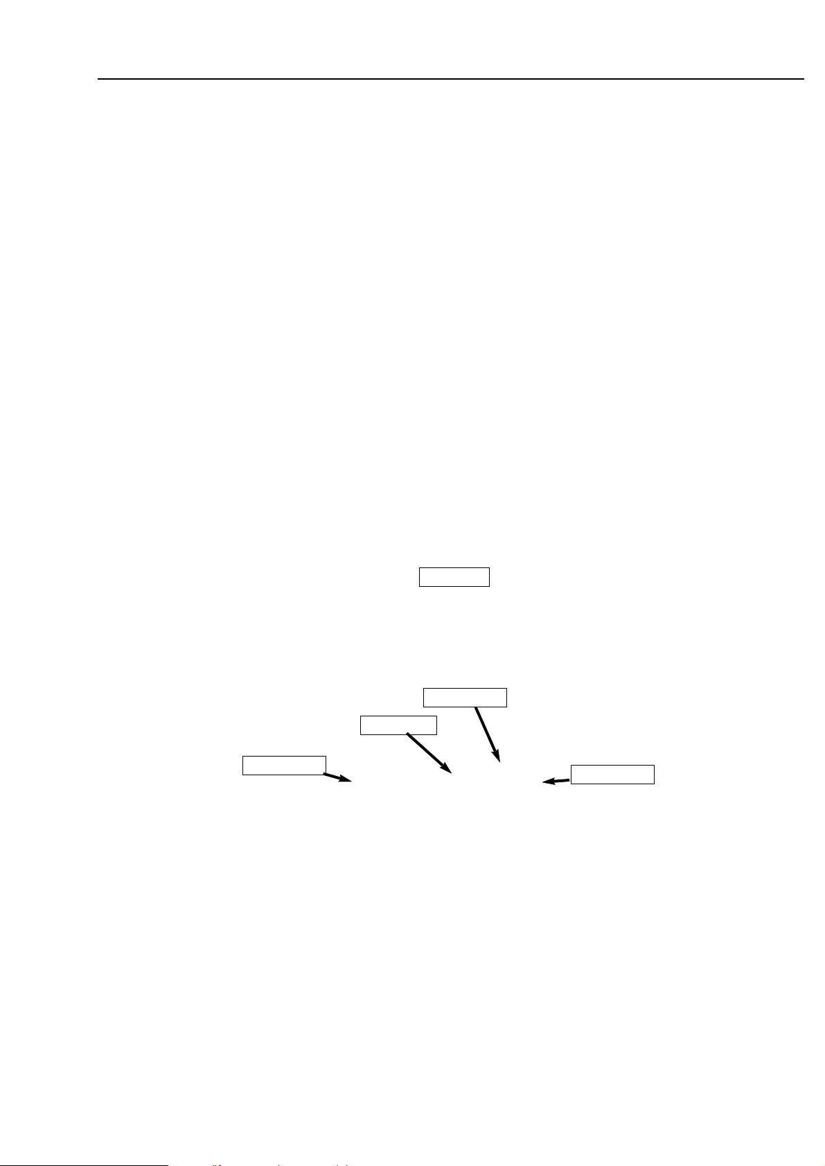
BLOCK DIAGRAM
Power ON:
FRONT BOARD
Standby Key 1214 → Line KEY2 → Microprocessor 7001.
Microprocessor 7001 sends an I2C command to Shiftregister
7403 on
AF9 BOARD
D5 (7403/11) = AMP_ON is set to high level.
Line AMP_ON is connected to the
POWER BOARD
If AMP_ON is high → power amplifiers 7301 and 7302 are
switched on.
CDR ON:
FRONT BOARD
CDR Key 1002 → Line KEY2 → Microprocessor 7001.
Microprocessor 7001 sends an I2C command to Shiftregister
7403 on
AF9 BOARD
D1 (7403/6) = VCD/CDR_ON is set to high level.
Line VCD/CDR_ON is connected to the
POWER BOARD
On the Power Board the line is called VCD_ON.
If this line is high → +5V_VCD and +12V_CDR are switched
on.
CDR MODULE
gets supply voltages via 1312 → 1214.
 Loading...