

Page 1

Service Manual
MP3 3CDC Mini System
FWM352,FWM371
all versions
TABLE OF CONTENTS
Handling chip components ............................................................1-1
Information about lead-free soldering............................................1-2
Technical specification...................................................................2-1
Service tools ..................................................................................2-1
Service measurement setup..........................................................2-2
Connections and controls.......................................................3-1..3-3
Maintenance and troubleshooting .................................................3-4
Disassembly diagram .............................................................4-1..4-2
Set block diagram..........................................................................5-1
Set wiring diagram.........................................................................5-2
FRONT BOARD
circuit diagram ..........................................................................6-1
layout diagram...................................................................6-2..6-3
circuit diagram(mic part) ...........................................................6-4
layout diagram(ant&currouse motor&drawer motor board) ......6-4
MAIN BOARD
circuit diagram(tuner part).........................................................7-1
circuit diagram(tape part)..........................................................7-2
circuit diagram ..........................................................................7-3
layout diagram ...................................................................7-4..7-5
AMP BOARD
circuit diagram ..........................................................................8-1
layout diagram ..........................................................................8-2
POWER BOARD
circuit diagram ..........................................................................9-1
layout diagram(for FWM352) ....................................................9-2
layout diagram(for FWM371)....................................................9-2
3CDC BOARD
circuit diagram ............................................................. 10-1..10-2
layout diagram ...............................................................10-3..10-4
Exploded view diagram................................................................11-1
Mechanical partslist .....................................................................11-2
Electrical partslist................................................................12-1..12-6
New main board and Front board W/S 3.1
circuit diagram
layout diagram ...............................................................13-1..13-6
Revision list..................................................................................14-1
CLASS 1
©
Copyright 2007 Philips Consumer Electronics B.V. Eindhoven, The Netherlands
All rights reserved. No part of this publication may be reproduced, stored in a retrieval
system or transmitted, in any form or by any means, electronic, mechanical, photocopying,
or otherwise without the prior permission of Philips.
Published by LX 0729 Service Audio Printed in The Netherlands Subject to modification
LASER PRODUCT
3141 785 30763
Version 1.3
Page 2

1 - 1
HANDLING CHIP COMPONENTS
Page 3

1 - 2
INFORMATION ABOUT LEAD-FREE SOLDERING
Philips CE is producing lead-free sets from 1.1.2005 onwards.
IDENTIFICATION:
Regardless of special logo (not always indicated) one must treat all sets from 1 Jan 2005 onwards, according next rules:
Example S/N:
• Use only lead-free solder alloy Philips SAC305 with order code 0622 149 00106. If lead-free solder-paste is required, please contact
the manufacturer of your solder-equipment. In general use of solder-paste within workshops should be avoided because paste is not
easy to store and to handle.
• Use only adequate solder tools applicable for lead-free solder alloy. The solder tool must be able
• Adjust your solder tool so that a temperature around
• Mix of lead-free solder alloy / parts with leaded solder alloy / parts is possible but PHILIPS recommends strongly to avoid mixed
• Use only original spare-parts listed in the Service-Manuals. Not listed standard-material (commodities) has to be purchased at
• Special information for BGA-ICs:
• For sets produced before 1.1.2005 (except products of 2004), containing leaded solder-alloy and components, all needed spare-parts
• On our website www.atyourservice.ce.Philips.com
o To reach at least a solder-temperature of 40
o To stabilize the adjusted temperature at the solder-tip
o To exchange solder-tips for different applications.
solder-joint should not exceed ~ 4 sec. Avoid temperatures above 400 otherwise wear-out of tips will rise drastically and flux-fluid
will be destroyed. To avoid wear-out of tips switch off un-used equipment, or reduce heat.
solder alloy types (leaded and lead-free).
If one cannot avoid or does not know whether product is lead-free, clean carefully the solder-joint from old solder alloy and re-solder
with new solder alloy (SAC305).
external companies.
- always use the 12nc-recognizable soldering temperature profile of the specific BGA (for de-soldering always use the lead-free
temperature profile, in case of doubt)
- lead free BGA-ICs will be delivered in so-called 'dry-packaging' (sealed pack including a silica gel pack) to protect the IC against
moisture. After opening, dependent of MSL-level seen on indicator-label in the bag, the BGA-IC possibly still has to be baked dry.
(MSL=Moisture Sensitivity Level). This will be communicated via AYS-website.
Do not re-use BGAs at all.
will be available till the end of the service-period. For repair of such sets nothing changes.
BGA-de-/soldering (+ baking instructions)
∗
Heating-profiles of BGAs and other ICs used in Philips-sets
∗
Bottom line of typeplate gives a 14-digit S/N. Digit 5&6 is the year, digit 7&8 is the week number,
so in this case 2005 wk12
So from 0501 onwards = from 1 Jan 2005 onwards
Im portant note
you avoid mixing solder-alloys ( leaded/ lead -free). So best to always use SAC3 05 and the
higher temperatures belong to th is.
Due to lead-free technology some rules have to be respected by the workshop during a repair:
: In fact also product s of year 2004 must be treated in this way as long as
− is reached and stabilized at the solder joint. Heating-time of the
you find more information to:
For additional questions please contact your local repair-helpdesk.
You will find this and more technical information within the "magazine", chapter "workshop news".
SERVICE INSTRUCTION
Safety regulations require that after a repair, the set must be returned in its original condition. Pay in particular attention to
the following points:
· Route the wire trees correctly and fix them with the
mounted cable clamps.
· Check the insulation of the AC Power lead for external
damage.
· Check the strain relief of the AC Power cord for proper
function.
· Check the electrical DC resistance between the AC Power
Plug and the secondary side (only for sets which have a AC
Power isolated power supply):
1. Unplug the AC Power cord and connect a wire
between the two pins of the AC Power plug.
2. Set the AC Power switch to the "on" position (keep the
AC Power cord unplugged!).
3. Measure the resistance value between the pins of the
AC Power plug and the metal shielding of the tuner or
the aerial connection on the set. The reading should be
larger than 4.5 Mohm (For U.S. it should be between
4.2 Mohm and 12 Mohm).
4. Switch "off" the set, and remove the wire between the
two pins of the AC Power plug.
• Check the cabinet for defects, to avoid touching of any
inner parts by the customer.
Page 4

2 - 1
TECHNICAL SPECIFICATIONS
GENERAL
Mains voltage
Mains frequency
Battery
Power consumption
Dimension (W x H x D)
Weight
(excluding packing and batteries)
FWM352/12
FWM352/55
FWM352/98
FWM371/55
FWM352/12
FWM352/55
FWM352/98
FWM371/55
remote
normal
normal
Standby
:
230V
:
120/230V
:
120/230V
:
120/230V
:
50 Hz
:
60 Hz
50/
:
50/60 Hz
:
50/60 Hz
::3 V (AAA x 2)
<
70W (FWM352)
<
80W (FWM371)
:< 15 W
: 265 x 310 x 384 mm
::5.5 Kg
AMPLIFIER
Output power mains
Speaker impedance
Frequency response
mains
:2 x 50W
2 x 4 ohm
:
:
20 Hz - 20 kHz (±3dB)
TUNER - FM SECTION
Tuning range : 87.5 - 108 MHz
IF frequency
Sensitivity
Selectivity
IF Rejection
Image Rejection
Distortion
Tuning Grid
300kHz : > 33 dB
: 10.7 MHz ± 0.02 MHz
:< 22 dBf at 26dB
:> 60 dB
:> 25dB
:< 3 %
:
50K Hz
TUNER - AM SECTION
Tuning range :
Tuning Grid
IF frequency
Sensitivity
Selectivity S9/300kHz
IF rejection
Distortion
Image rejection
531 - 1602 kHz
: 530 - 1700 kHz
:
9/10K Hz
:
450 kHz ± 1 kHz
≤ 3.25 mV/m at 26dB
:
:
:> 12 dB
:
:> 24 dB
:< 5%
:
:> 20 dB
AUDIO CASSETTE RECORDER
Number of tracks : 1 stereo
Tape speed : 4.76 cm/sec + 3/-2%
Wow & flutter : < 0.4 % JIS Unwtd.
Fast wind/rewind C60 : < 130 sec.
Frequency response P/B : 100 - 8000 Hz
S/N ratio : > 36 dB
COMPACT DISC
S/N ratio unwtd. > 50 dB
Channel difference 1 kHz : < 2 dB
Crosstalk 1 kHz : > 30 dB
Frequency response : ± 2dB at 100Hz
THD(1kHz,0dB) : 1.5%
:
SERVICE TOOLS
Audio signal disc SBC 429.......................................................................4822 397 30184
Playability test disc SBC 444
Test disc 5 (disc without errors ) +
Test disc 5A (disc with dropout errors, black spots and fingerprints)
SBC 426/426A.....................................................................4822 397 30096
Burn in test disc (65 min. 1kHz signal at -30 dB level without “pause”)
...................................................................4822 397 30245
.....4822 397 30155
AVAILABLE ESD PROTECTION EQUIPMENT
anti-static table mat
anti-static wristband
connection box (3 press stud connections, 1MΩ) 4822 320 11307
extendible cable (2m, 2MΩ, to connect wristband to connection box) 4822 320 11305
connecting cable (3m, 2MΩ, to connect table mat to connection box) 4822 320 11306
earth cable (1MΩ, to connect any product to mat or to connection box) 4822 320 11308
KIT ESD3 (combining all 6 prior products - small table mat) 4822 310 10671
wristband tester 4822 344 13999
large 1200x650x1.25mm 4822 466 10953
small 600x650x1.25m 4822 466 10958
4822 395 10223
Page 5

2 - 2
S
ERVICE MEASUREMENT
Tuner SW
RF Generator
e.g. PM5326
Aerial replacement
DUT
Capacitor
Ri=50Ω
R=50Ω
Bandpass
250Hz-15kHz
e.g. 7122 707 48001
LF Voltmeter
e.g. PM2534
S/N and distortion meter
e.g. Sound Technology ST1700B
To avoid atmospheric interference all AM-measurements have to be carried out in a Faraday«s cage.
Use a bandpass filter (or at least a high pass filter with 250Hz) to eliminate hum (50Hz, 100Hz).
Tuner AM (MW,LW)
RF Generator
e.g. PM5326
Ri=50Ω
DUT
Frame aerial
e.g. 7122 707 89001
Bandpass
250Hz-15kHz
e.g. 7122 707 48001
LF Voltmeter
e.g. PM2534
S/N and distortion meter
e.g. Sound Technology ST1700B
To avoid atmospheric interference all AM-measurements have to be carried out in a Faraday«s cage.
CD
Use Audio Signal Disc SBC429 4822 397 30184 (replaces test disc 3)
L.P.F. = 13
th
order filter 4822 395 30204
DUT
L
R
Low pass filter 22kHz
LEVEL METER
e.g. Sennheiser UPM550
with FF-filter
S/N and distortion meter
e.g. Sound Technology ST1700B
Page 6

3 - 1
P
i
CONNECTION AND CONTROLS
ons
reparat
Connecting other equipment to your
system
Use a cinch cable to connect AUX/CDR to the
analogue audio out terminals of an external
equipment (TV, VCR, Laser Disc player, DVD
player or CD Recorder).
Optional connection
The optional equipment and connecting cords
are not supplied. Refer to the operating
instructions of the connected equipment for
details.
Note:
– If you are connecting equipment with a mono
output (a single audio out terminal), connect it to
the AUX/CDR left terminal. Alternatively, you can
use a “single to double” cinch cable (the output
sound still remain mono).
Inserting batteries into the
remote control
Insert two batteries (Type R03 or AAA) into the
remote control with the correct polarity as
indicated by the "+" and "-" symbols inside
the battery compar tment.
2
CAUTION!
– Remove batteries if they are exhausted
or will not be used for a long time.
– Do not use old and new or different
types of batteries in combination.
– Batteries contain chemical substances, so
they should be disposed of properly.
FM Antenna
FM wire antenna
For better FM stereo reception, connect an
outdoor FM antenna to the FM ANTENNA
terminal.
Front Speakers
Connect the speaker wires to the SPEAKERS
terminals, right speaker to "R" and left speaker to
"L", coloured (marked) wire to "+" and black
(unmarked) wire to "-".
C Speakers Connection
(left)
Speaker
this happens, let the system cool down
1
Fully insert the stripped portion of the speaker
wire into the terminal as shown.
before reusing it (not available for all versions).
Connect the supplied MW loop antenna and FM
B Antennas Connection
Notes:
–For optimal sound performance, use the
supplied speakers.
– Do not connect more than one speaker to any
antenna to the respective terminals. Adjust the
position of the antenna for optimal reception.
MW Antenna
speaker terminals.
-
/
+
– Do not connect speakers with an impedance
lower than the speakers supplied. Please refer to
the SPECIFICATIONS section of this manual.
one pair of
2
1
Fix the claw
to the slot
3
MW ANTENNA
Position the antenna as far as possible from a TV,
VCR or other radiation source.
antenna
MW loop
Preparations
B
AM ANTENNA
FM ANTENNA
Speaker
R L
AUX/CDR
(right)
C
+
Ò
L
R
SPEAKERS 6
AC power cord
A
Rear connections
The type plate is located at the rear of the
system.
For users in the U.K.: please follow the
instructions on page 2.
Before connecting the AC power cord to the
wall outlet, ensure that all other connections
have been made.
WARNING!
–For optimal performance, use only the
original power cable.
–Never make or change any connections
with the power switched on.
– High voltage! Do not open.You run the
risk of getting an electric shock.
A Powe r
– The machine does not contain any user-
serviceable parts.
– Modification of the product could result
in hazardous radiation of EMC or other
unsafe operation.
To avoid overheating of the system, a safety
circuit has been built in. Therefore, your
system may switch to Standby mode
automatically under extreme conditions. If
Page 7

3 - 2
CONNECTION AND CONTROLS
5 6
ALBUM (-/ +)
SEARCH•TUNING
for MP3-CD ............. to select previous/next
! Mode Selection
Controls on the system and
remote control
STANDBY-ON/ ECO POWER (B)
– switches the system on or to Eco Power
Controls (illustrations on page 3)
1
album.
backward/forward.
radio frequency.
for CD/ MP3-CD .. (press and hold) to search
for Tuner ..................... to tune to a lower or higher
for Clock .................... to set the hour.
standby/normal standby with clock display.
DISC (CD 1/2/3)
TUNER
2 Source selection – to select the following:
– to select disc tray 1, 2 or 3.
programme.
9
STOP
for CD/ MP3-CD .. to stop playback or to clear a
for Tuner ..................... (on the system only) to stop
TAPE
– to select waveband: FM or MW.
– to select tape deck.
programming.
activate/deactivate the
demonstration.
for Demo ................... (on the system only) to
for Clock .................... to exit clock setting.
for Plug&Play ............ (on the system only) to exit
AUX
AUX.
3 iR SENSOR
– to select the input for an additional appliance:
4 VOLUME (VOL +/-)
– infrared sensor for remote control.
plug&play mode.
2;
PLAY•PAUSE
for CD/ MP3-CD .. to start or interr upt playback.
DBB 2, DBB 3 or DBB OFF).
5 DBB
– to increase or decrease the volume.
– to select the desired bass boost level. (DBB 1,
6 DSC
the current, previous, or next
track.
station.
¡ ™
for MP3-CD ............ to select previous/next title.
for CD ........................ to skip to the beginning of
for Tuner .................... to select a preset radio
PRESET / ( TITLE)
settings (OPTIMAL, TECHNO, ROCK or JAZZ).
7 DISC 1/2/3
– Selects different types of preset sound equaliser
for Clock ................... to set the minute.
@ DISC CHANGE
8 Display screen
– to select a disc tray for playback.
9 OPEN•CLOSE
– to view the current status of the system.
–to change disc(s).
– to open or close the disc tray.
# CLOCK•TIMER
$ n
– to view the clock.
– set the clock or set the timer (on the set only).
– to connect headphones.
stations.
for CD/ MP3-CD .. to programme disc tracks.
for Tuner ..................... to programme preset radio
0 PROGRAM
1
y
MUTE
AUX
TUNER
CD1/2/3
2
£
PROGRAM SHUFFLE
REPEAT
™
0
VOL
4
TITLE
!
ALBUM
¡
TIMER
SLEEP
ON/OFF
DIM
DISPLAY
()6
DBB
DSC
5
2
3
8
4
7
5
$@#
&
*
1
6
^9%
0
!
Page 8

3 - 3
CONNECTION AND CONTROLS
Controls
% MIC IN
^ MIC VOLUME
– to connect microphone
& Ta pe Deck Operation
– to adjust the mixing level for Karaoke
5 6
•
RECORD ...starts recording.
PLAY 2 ............ starts playback.
SEARCH / fast rewinds/winds the tape.
9
compartment.
;
................................. stops the tape; opens the tape
STOP•OPEN 0
PAUSE ....... interrupts recording or playback.
2;
, for example).
,
Notes for remote control:
– First, select the source you wish to control
by pressing one of the source select keys on
the remote control (CD or TUNER, for
screen : DIM 1, DIM 2, DIM 3 or DIM OFF.
* Disc tray
( DISPLAY
) DIM MODE
– to select disc information display mode.
¡ SLEEP (TIMER ON/OFF)
– to select different brightness for the display
– to activate/deactivate or set the sleep timer.
– activates/deactivates the timer function.
™ REPEAT
repeatedly.
– to playback track(s)/disc(s)/programme
MUTE
≤
£ SHUFFLE
– turns on/off the random play mode.
–mutes or restores the volume.
example).
– Then select the desired function ( ,
¡ ™
Page 9

3 - 4
MAINTENANCE AND TROUBLESHOOTING
If the signal is too weak, adjust the antenna or
connect an external antenna for better
reception.
Increase the distance between the Mini HiFi
System and your TV or VCR.
Clean deck parts, see “Maintenance”.
Use only NORMAL (IEC I) tape.
Apply a piece of adhesive tape over the missing
tab space.
Remove and reconnect the AC power plug and
switch on the system again.
Adjust the volume.
Disconnect the headphones.
Check that the speakers are connec ted
correctly.
Check if the stripped speaker wire is clamped.
Make sure the MP3-CD was recorded within
32-256 kbps bit rate with sampling frequencies
at 48 kHz, 44.1 kHz or 32 kHz.
¡ ™
2
Check the speaker connections and location.
Select the source (CD or TUNER, for example)
before pressing the function button ( , , ).
Reduce the distance between the remote
control and the system.
Insert the batteries with their polarities
(+/– signs) aligned as indicated.
Replace the batteries.
Point the remote control directly towards the IR
sensor.
Set the clock correctly.
Press and hold TIMER ON/OFF to switch on the
timer.
If recording or tape dubbing is in progress, stop
recording.
Press DIM to select DIM OFF display mode.
Power has been interrupted or the power cord
has been disconnected. Reset the clock/timer.
Radio reception is poor.
Cleaning the Heads and the Tape Paths
Recording or playback cannot be made.
pressure roller(s) C after every 50 hours of
To ensure good recording and playback quality,
clean the heads A, the capstan(s) B, and
tape operation.
Use a cotton swab slightly moistened with
The system does not react when buttons
are pressed.
Sound cannot be heard or is of poor
quality.
cleaning fluid or alcohol.
You also can clean the heads by playing a
cleaning tape once.
B
A
C CB
Demagnetising the heads
Use a demagnetising tape available at your
The left and right sound outputs are
dealer.
reversed.
The remote control does not function
properly.
The time is not working.
Not all lighted buttons are showing light.
Solution
Insert a disc.
The Clock/Timer setting is erased.
Check if the disc is inserted upside down.
Wait until the moisture condensation at the lens
has cleared.
Replace or clean the disc, see “Maintenance”.
Use a finalized CD-RW or a correct MP3-CD
format disc.
Use a finalised CD-RW or CD-R.
Cleaning the Cabinet
Use a soft cloth slightly moistened with a mild
detergent solution. Do not use a solution
containing alcohol, spirits, ammonia or abrasives.
Cleaning Discs
Maintenance
When a disc becomes dirty,
clean it with a cleaning cloth.
Wipe the disc from the centre
out. Do not wipe in circular
motion.
Do not use solvents such as
benzene, thinner, commercially available cleaners,
or antistatic spray intended for analogue records.
Cleaning the disc lens
After prolonged use, dirt or dust may
accumulate at the disc lens. To ensure good
playback quality, clean the disc lens with Philips
CD Lens Cleaner or any commercially available
cleaner. Follow the instructions supplied with
cleaner.
WARNING
Under no circumstances should you try to repair the system yourself, as this will invalidate the
warranty. Do not open the system as there is a risk of electric shock.
Tr oubleshooting
Problem
If a fault occurs, first check the points listed below before taking the system for repair. If you
are unable to remedy a problem by following these hints, consult your dealer or Philips for
help.
“NO DISC” is displayed.
“DISC NOT FINALIZED” is displayed.
Page 10

4 - 14 - 1
DISASSEMBLY DIAGRAM
Dismantling of the Cassette Cover
1) Loosen 4 screws to remove the Cassette Deck.
2) Loosen 4 screws to remove the Cassette Keys .
Dismantling of the CDC Module and Front Panel
1) Loosen 4 screws to remove the Cover T op of the set.
2) Loosen 2 screws to remove the Panel Left and 2 screws
to remove the Panel Right of the set.
3) Slide out the CDC T ray as shown in the diagram below with
the help of a flat head screw driver.
A
3) Push the catch outside and take out damper gear
assembly as indicated.
.
B
4)
Remove the Cassette Cover
as indicated.
4) Remove the Cover Tray CDC as indicated.
Sliding Out The CDC Tray
5) Loosen 2 screws A and 2 screws B to remove the CDC
Module as indicated.
6) Remove 2 screws at the bottom to separate the
Front Panel Assembly from the Plate Bottom .
Front View CDC
1
2
Remove CDC Module
Remove Cover Tray CDC
Page 11

4 - 2 4 - 2
DISASSEMBLY DIAGRAM
Dismantling of Rear Portion
A Remove the back panel :
A1 Remove screws M3x12 (4pcs)
A2 Remove screws M3x10 (14pcs)
A1
A2
B Remove Left and Right panel :
B1 Remove screws M3x10 (2pcs)
B2 Remove screws M3x10 (2pcs)
B1 B2
Dismantling of the Front Cabinet and PCB Boards
C Remove Front Cabinet:
Remove screws M3x10 (2pcs)
C
D Remove screws M3x10 (3pcs) E Remove screws M3x10 (12pcs)
D E
F Remove screws M3x10 (4pcs)
C
Page 12

5 - 15 - 1
SET BLOCK DIAGRAM
Page 13

5 - 2 5 - 2
SET WIRING DIAGRAM
Page 14

6 - 1 6 - 1
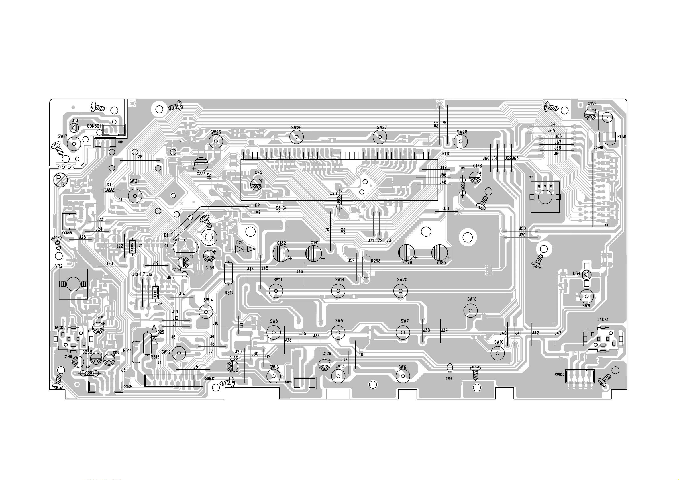
CIRCUIT DIAGRAM - FRONT BOARD
Page 15
6 - 26 - 2
CIRCUIT DIAGRAM - FRONT BOARD
Page 16
6 - 3 6 - 3
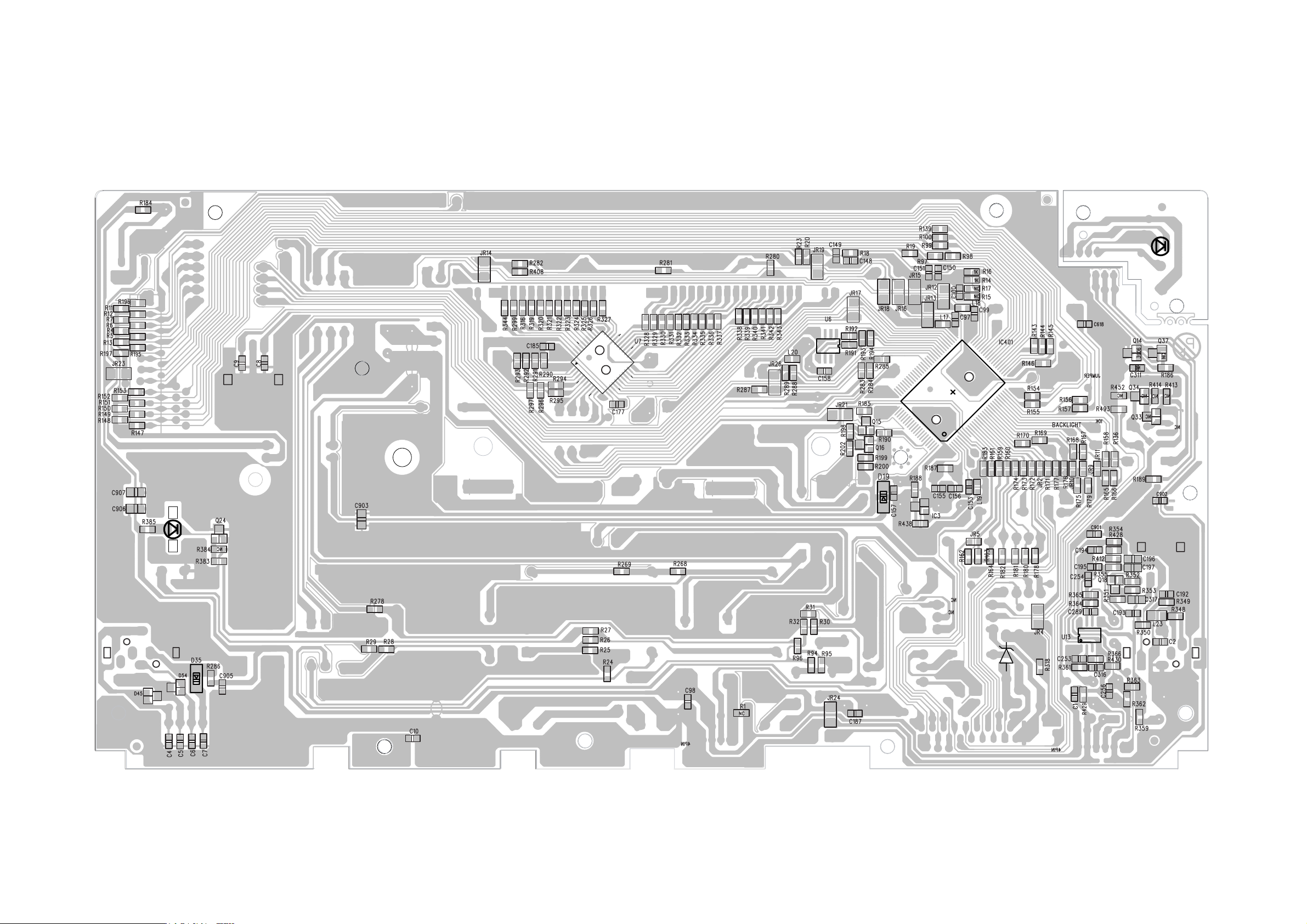
LAYOUT DIAGRAM - FRONT BOARD
Page 17
6 - 46 - 4
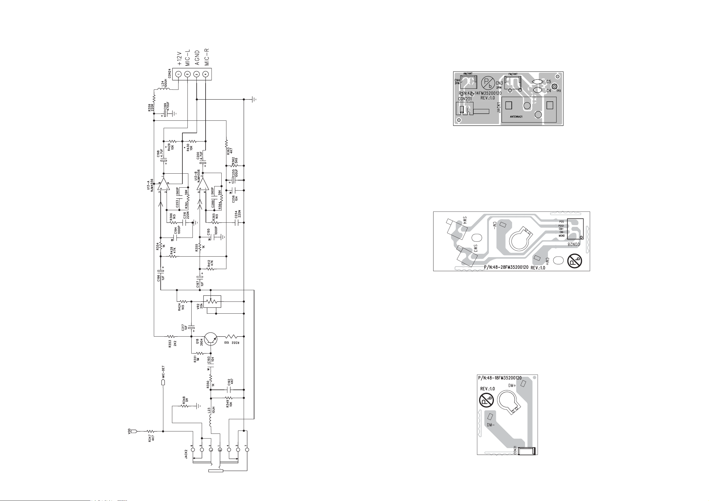
LAYOUT DIAGRAM - FRONT BOARD
MIC PART
LAYOUT DIAGRAM - CURROUSE MOTOR BOARD
LAYOUT DIAGRAM - ANT BOARD
LAYOUT DIAGRAM - DRAWER MOTOR BOARD
Page 18
7 - 1
7 - 1
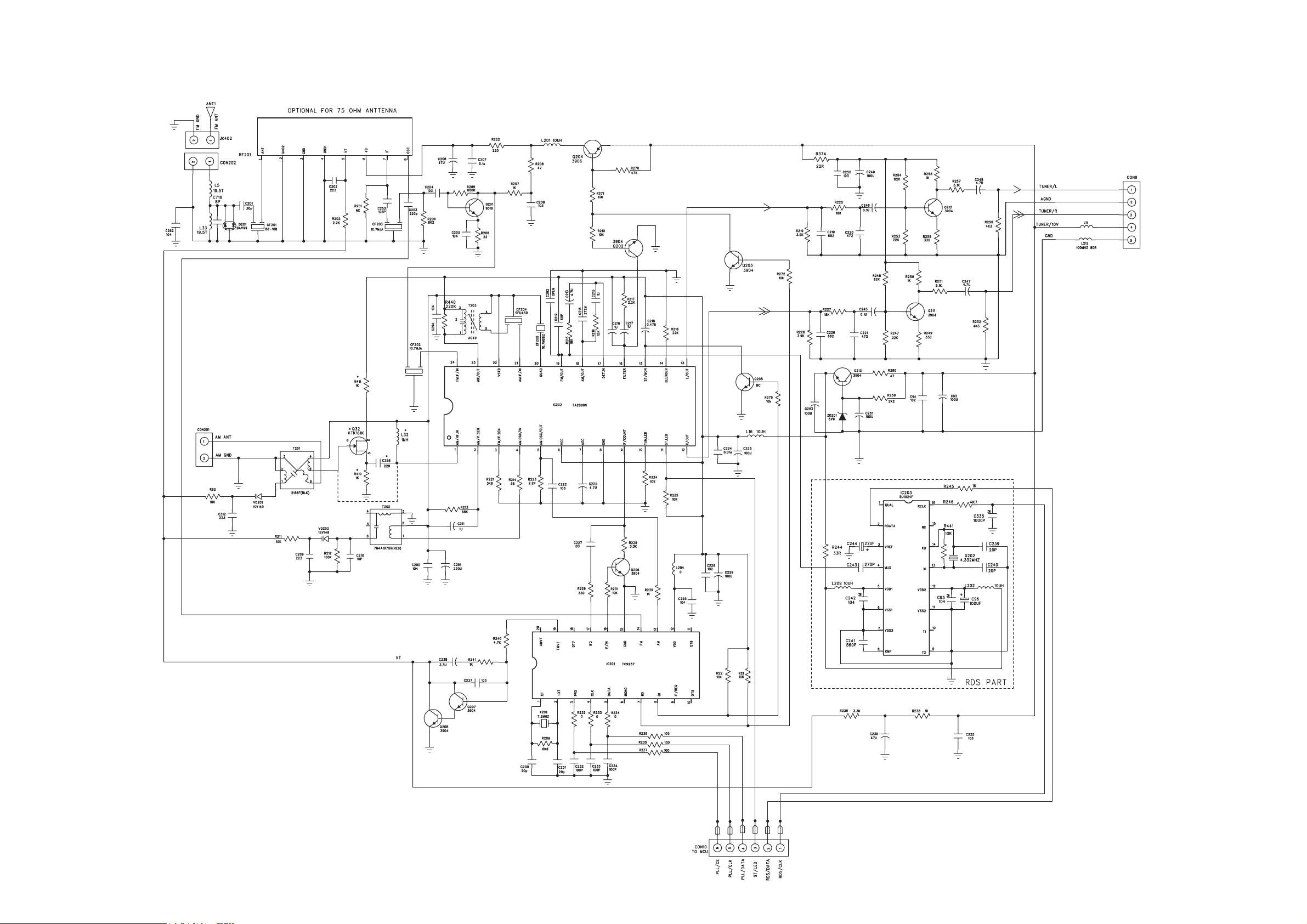
CIRCUIT DIAGRAM - MAIN BOARD
TUNER PART
Page 19
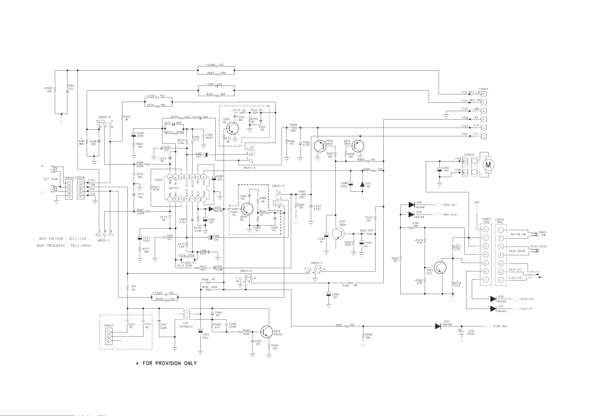
7 - 2
7 - 2
CIRCUIT DIAGRAM - MAIN BOARD
TAPE PART
Page 20
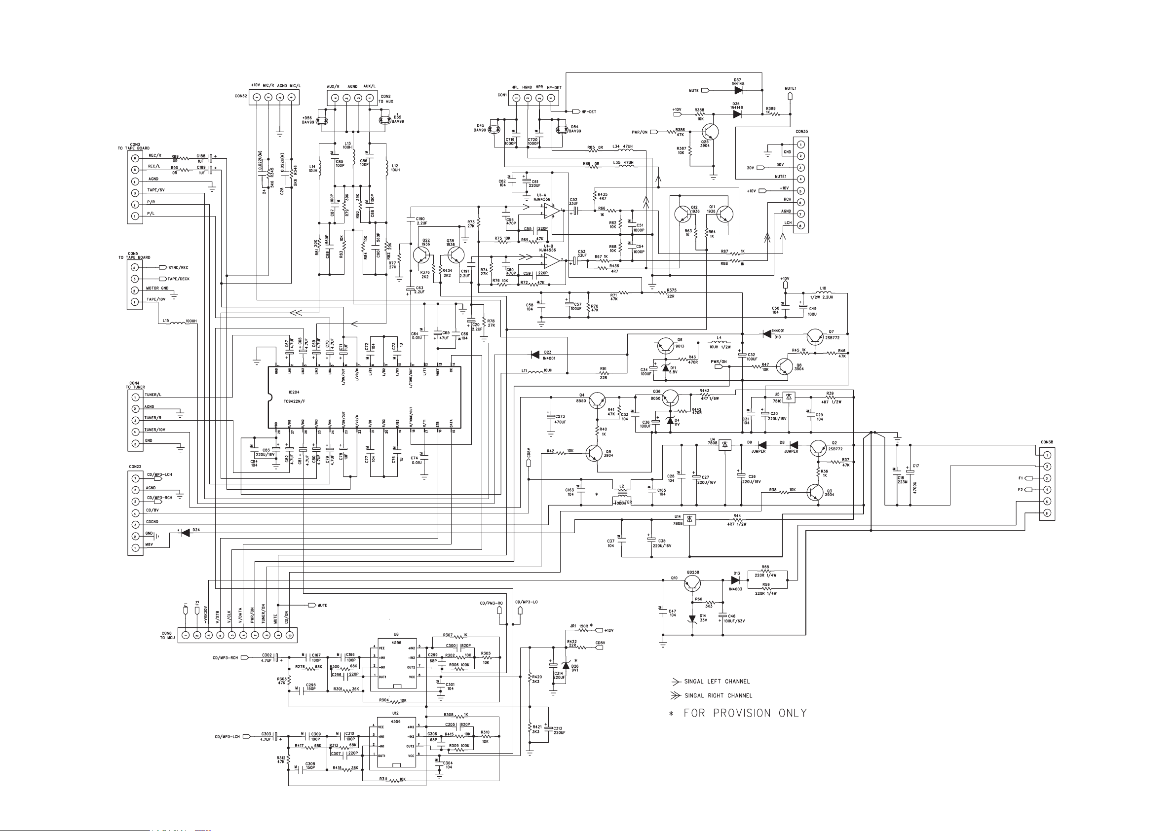
7 - 3
7 - 3
CIRCUIT DIAGRAM - MAIN BOARD
Page 21
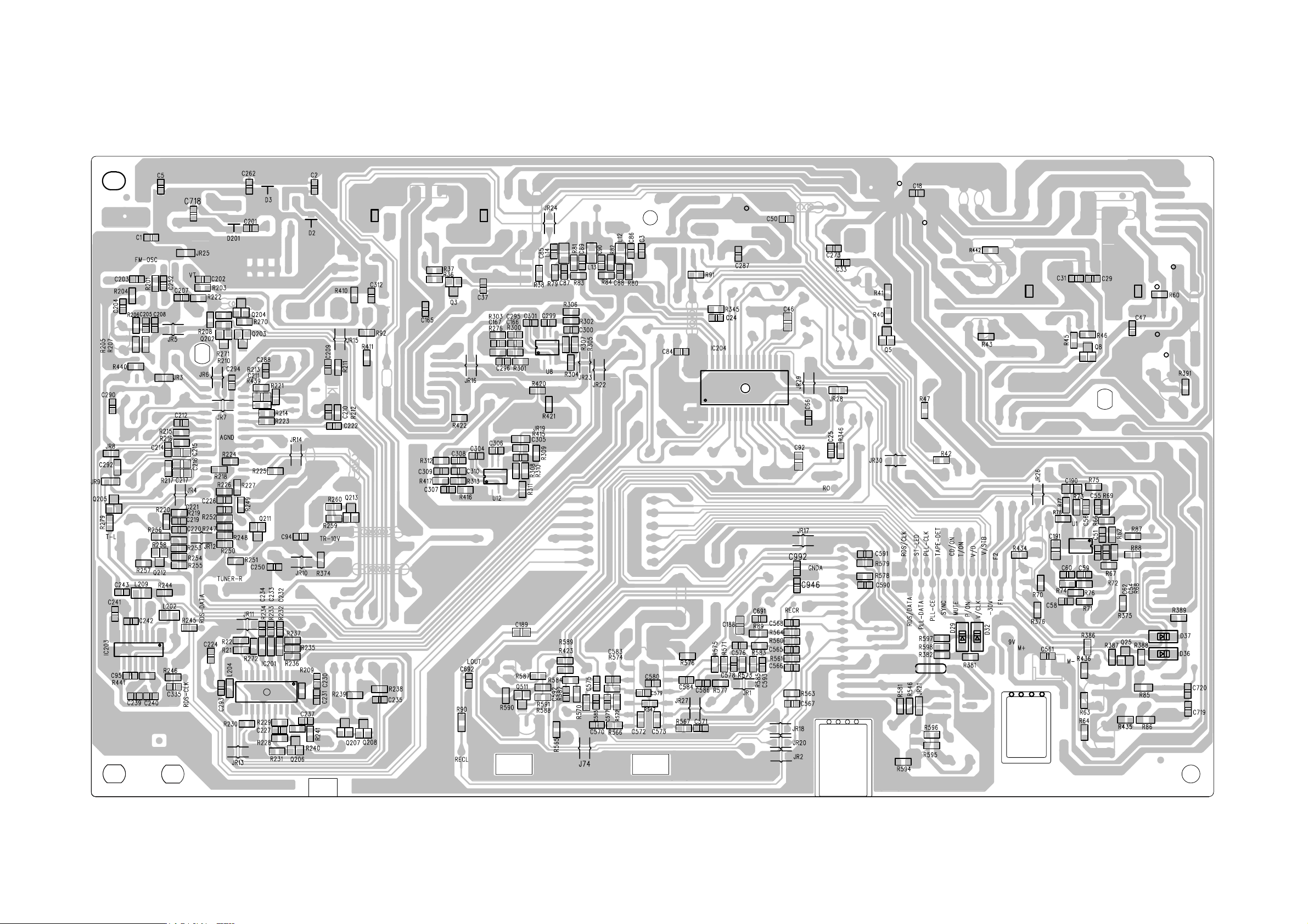
7 - 4 7 - 4
LAYOUT DIAGRAM - MAIN BOARD
Page 22
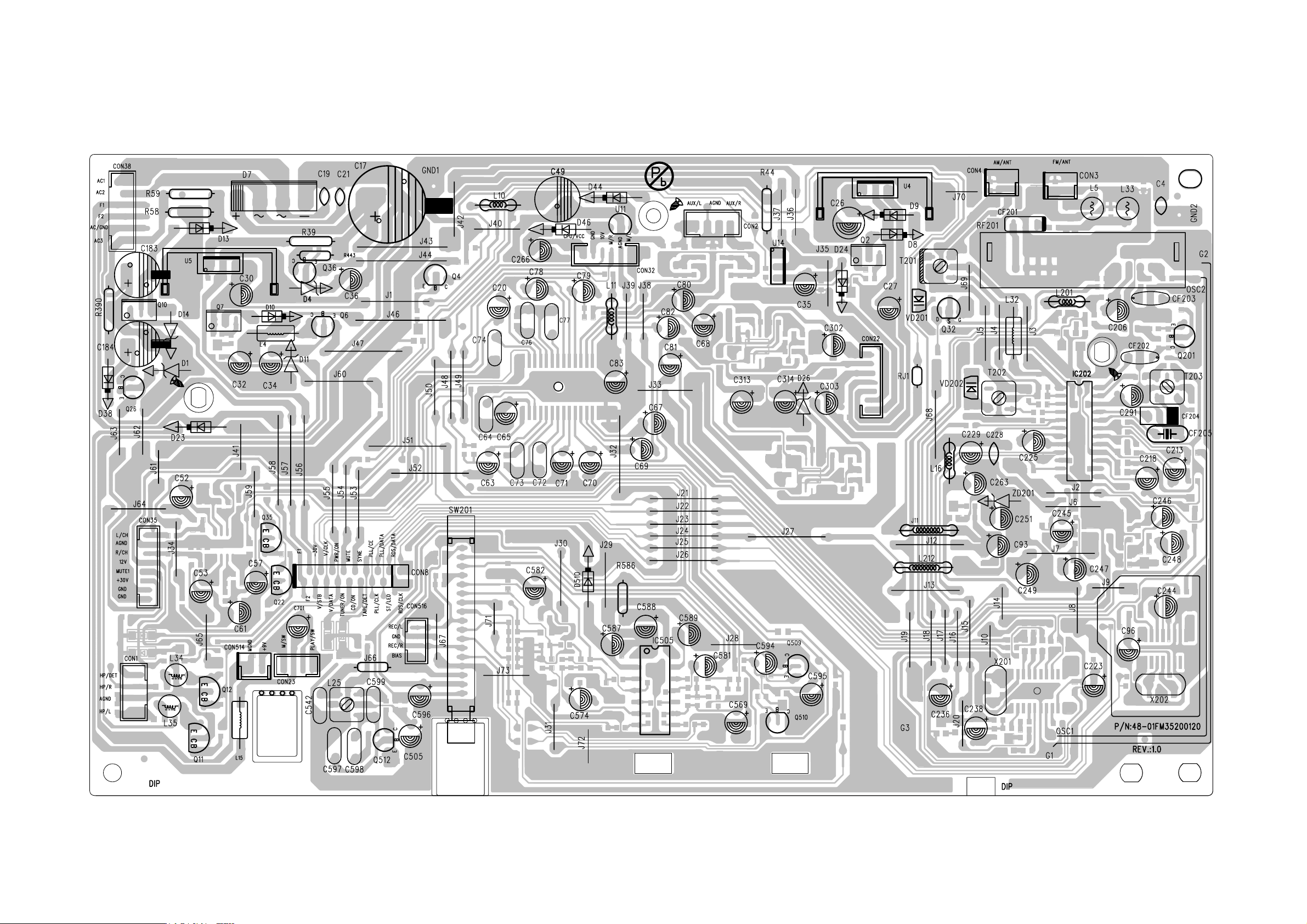
7 - 5 7 - 5
LAYOUT DIAGRAM - MAIN BOARD
Page 23
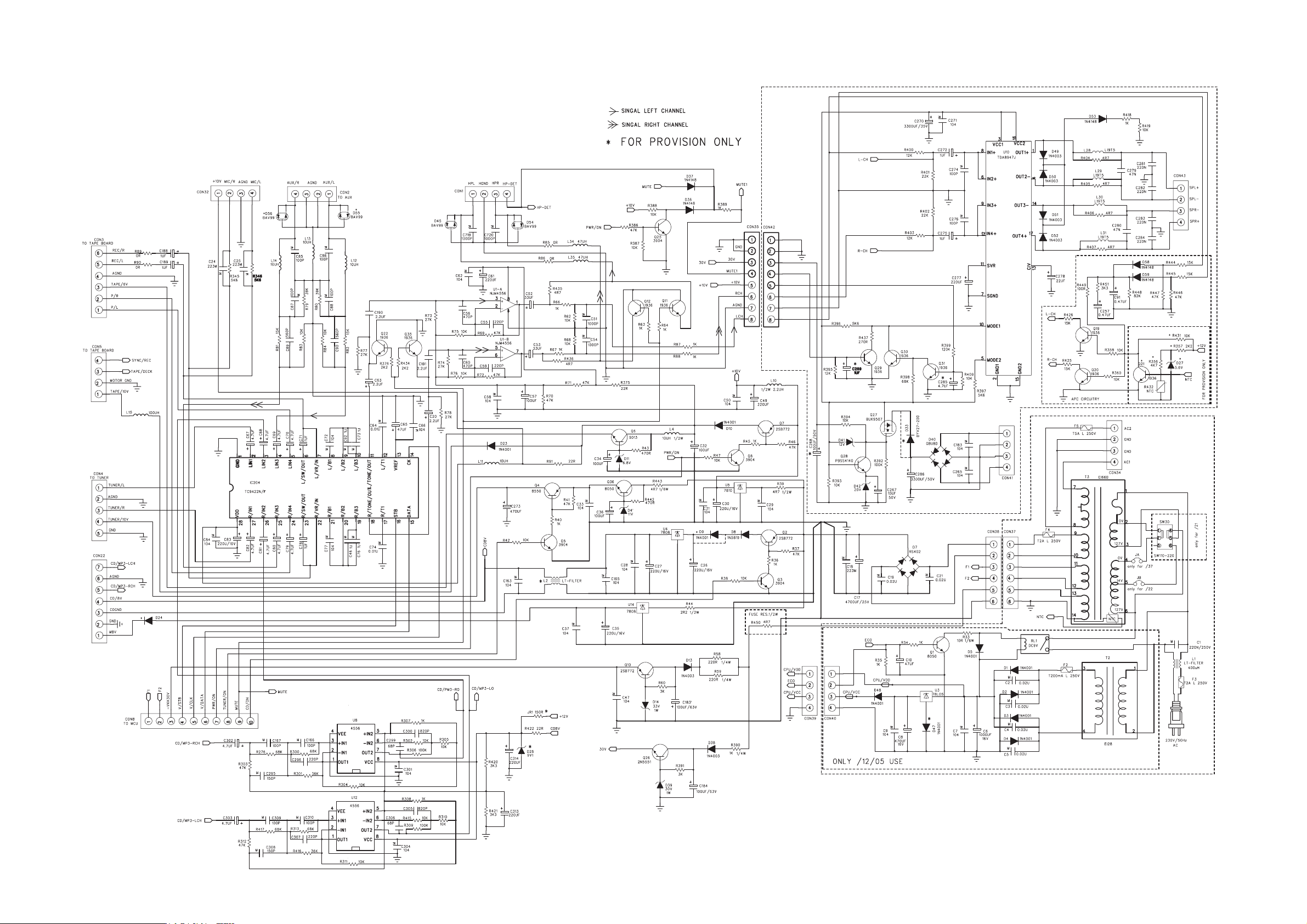
8 - 1 8 - 1
CIRCUIT DIAGRAM - AMP BOARD
Page 24
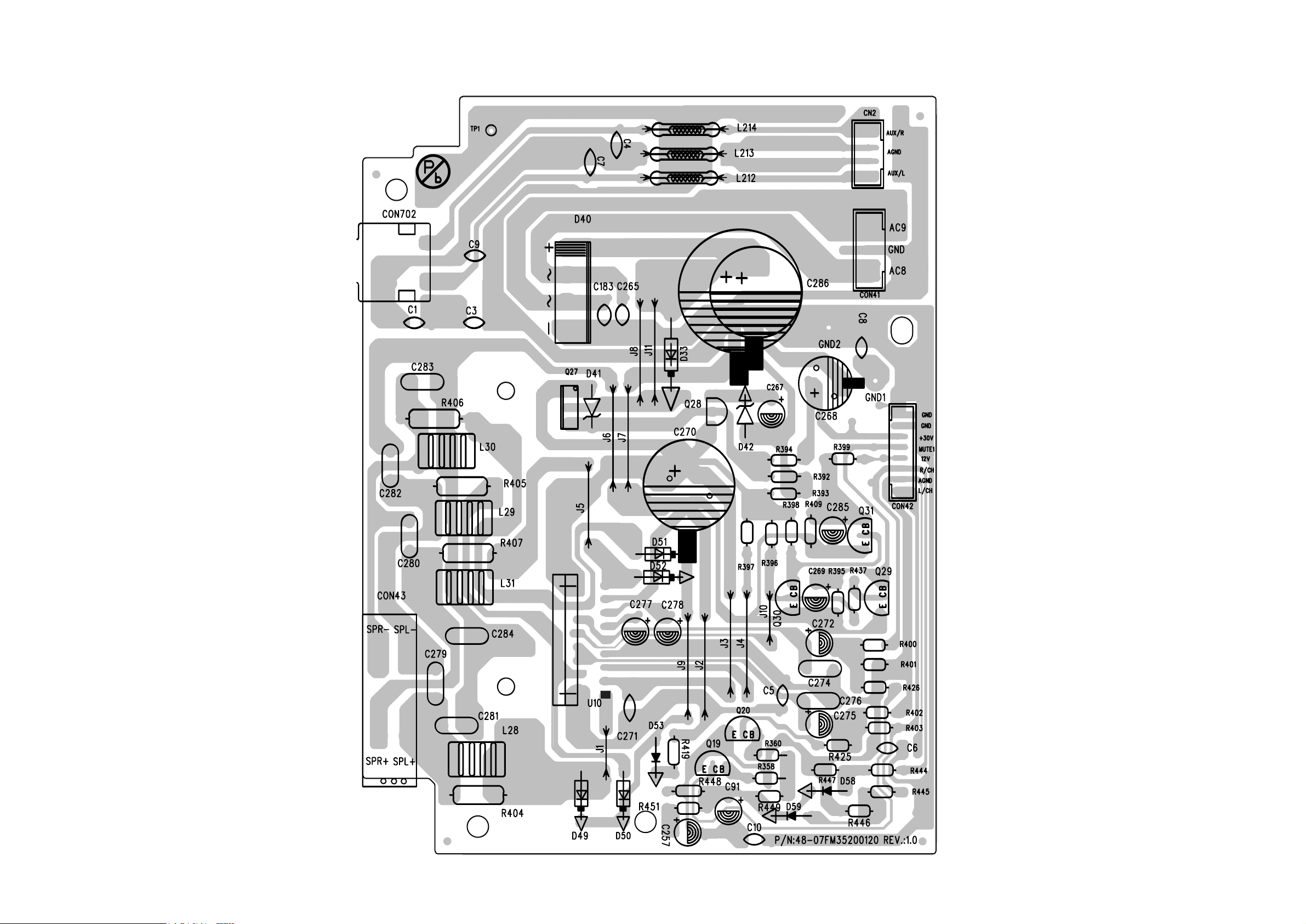
8 - 28 - 2
LAYOUT DIAGRAM - AMP BOARD
Page 25
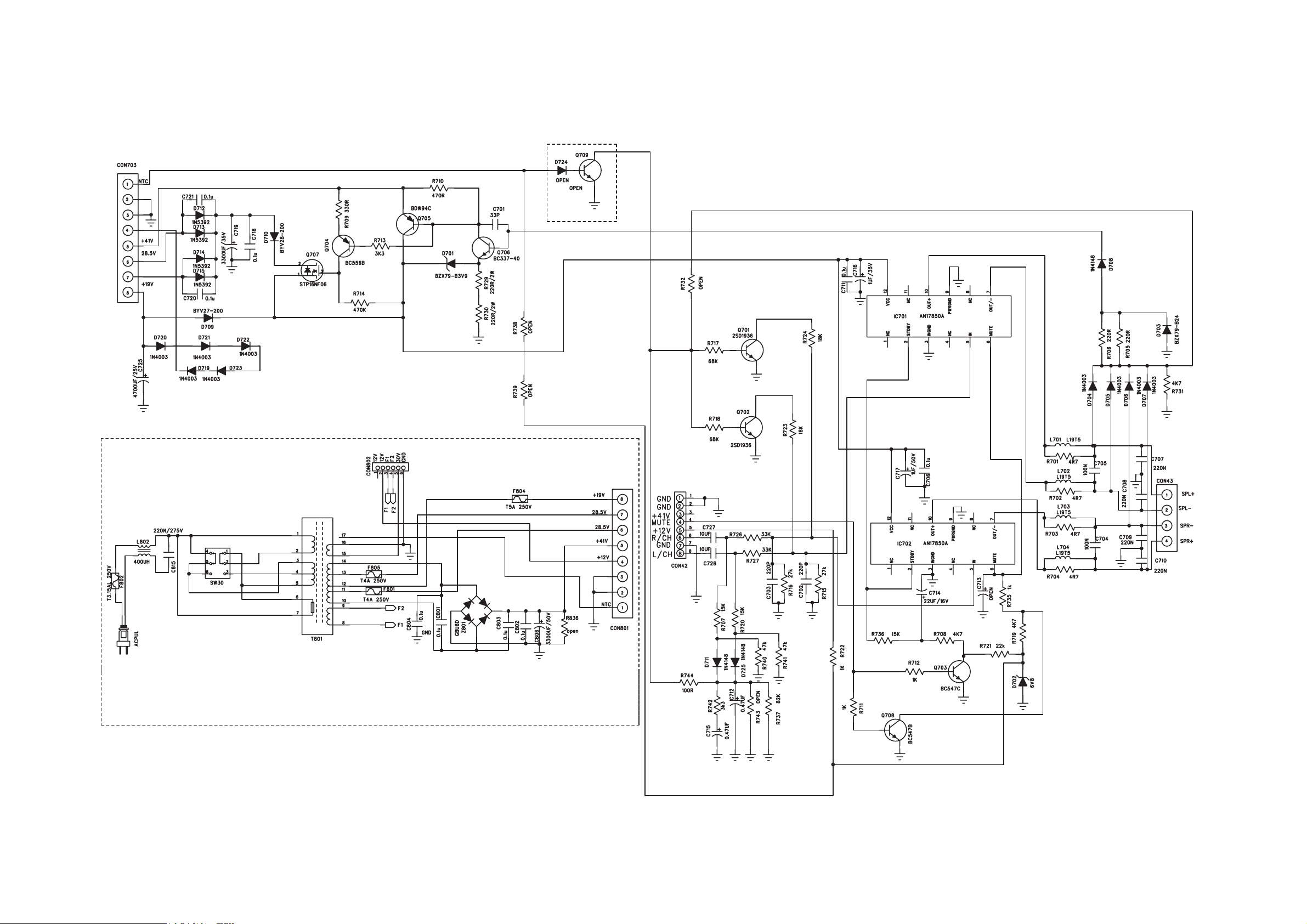
9 - 19 - 1
CIRCUIT DIAGRAM - POWER BOARD
Page 26
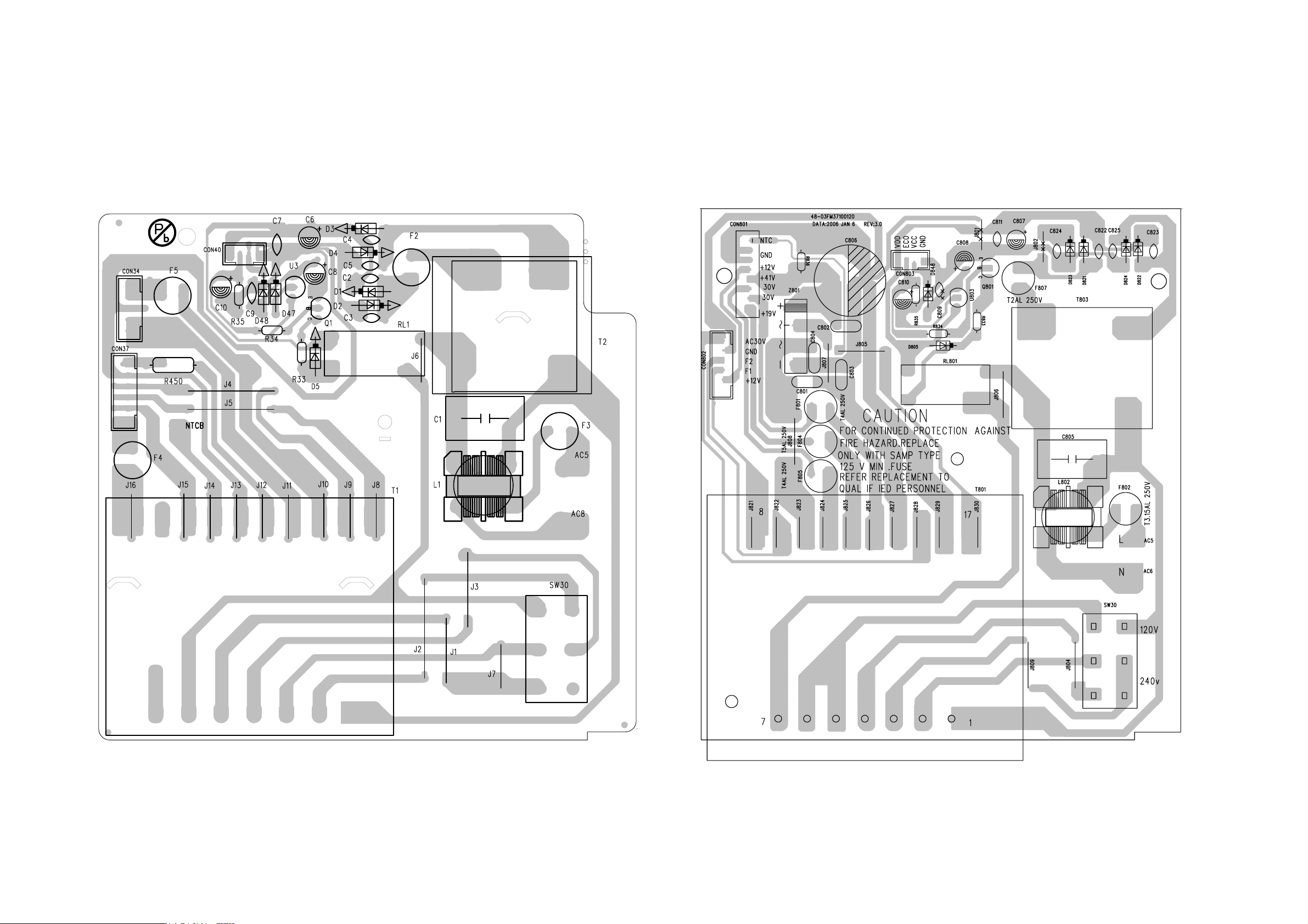
LAYOUT DIAGRAM - POWER BOARD
ONLY FOR FWM371
9 - 2 9 - 2
LAYOUT DIAGRAM - POWER BOARD
ONLY FOR FWM352
Page 27
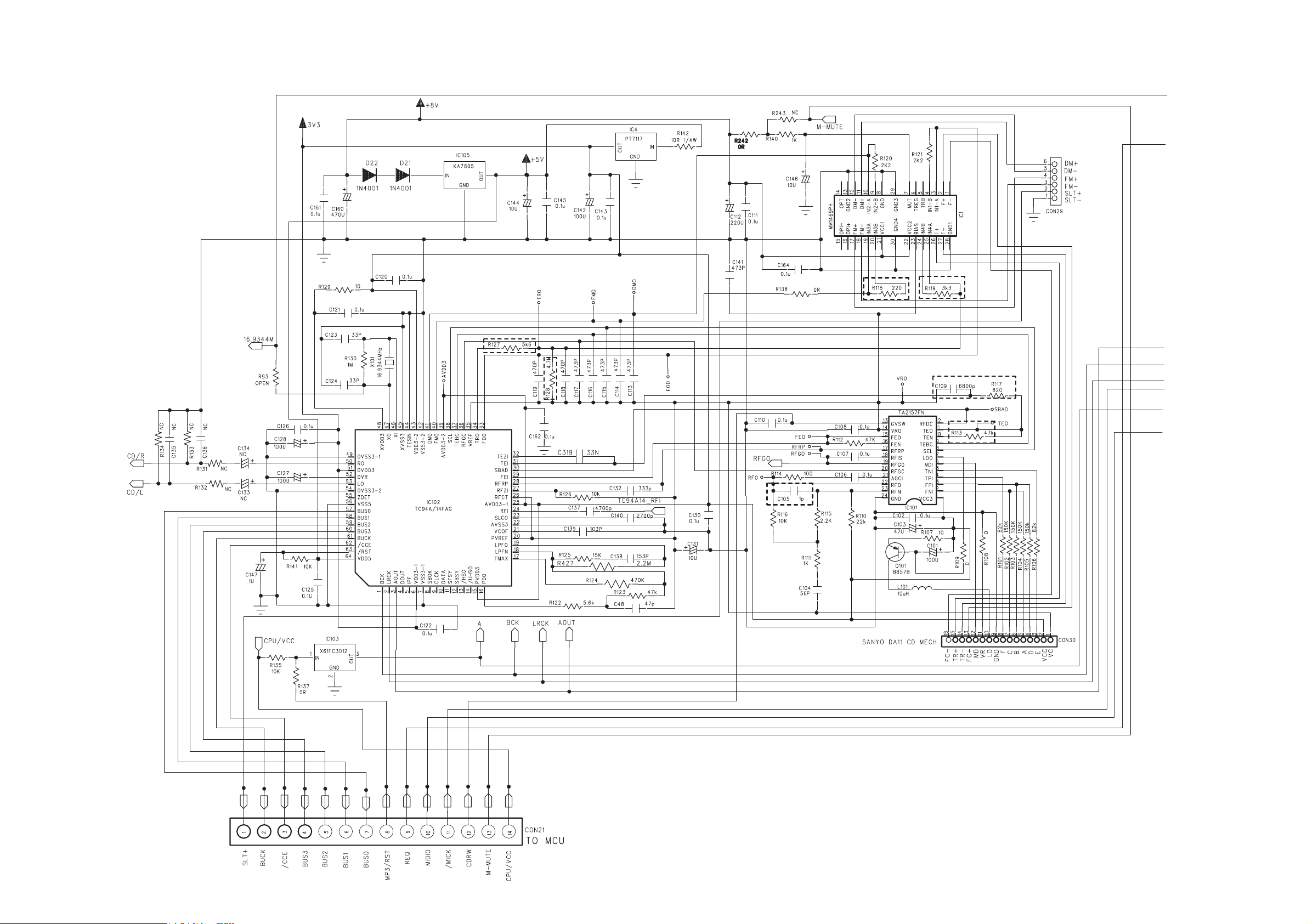
10 - 110 - 1
CIRCUIT DIAGRAM - 3CDC BOARD
PART1
Page 28
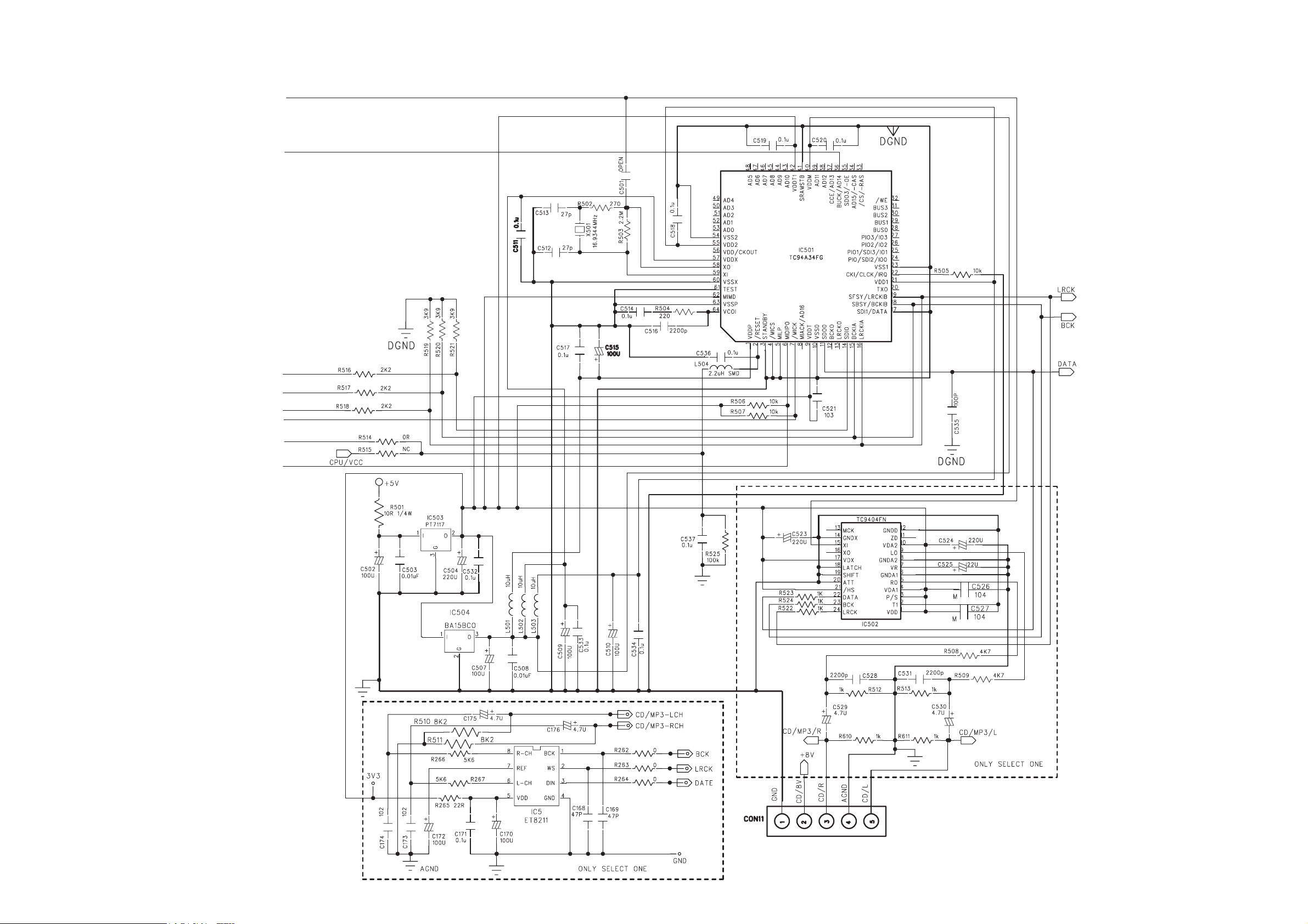
10 - 210 - 2
CIRCUIT DIAGRAM - 3CDC BOARD
PART2
Page 29
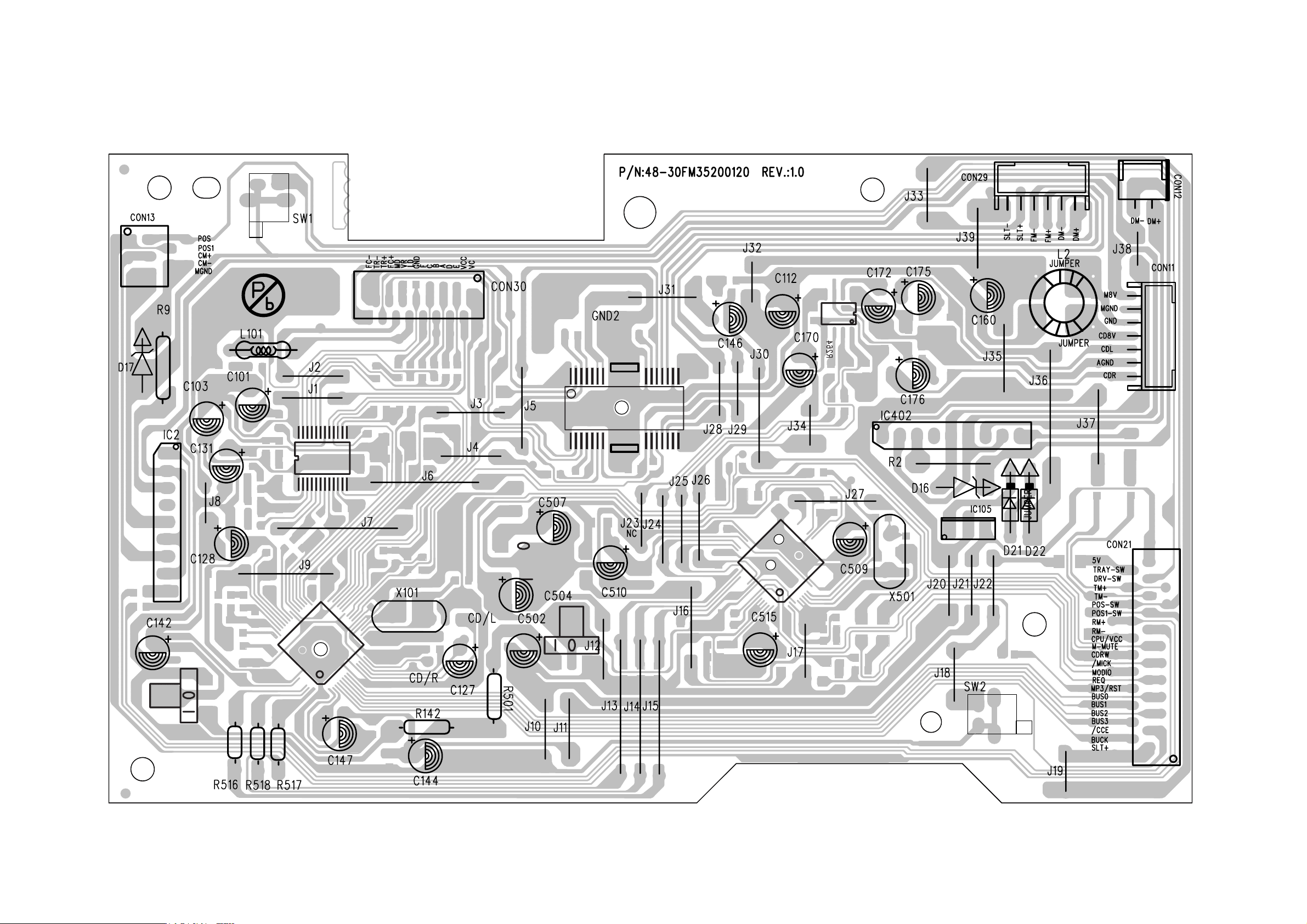
10 - 3 10 - 3
LAYOUT DIAGRAM - 3CDC BOARD
Page 30
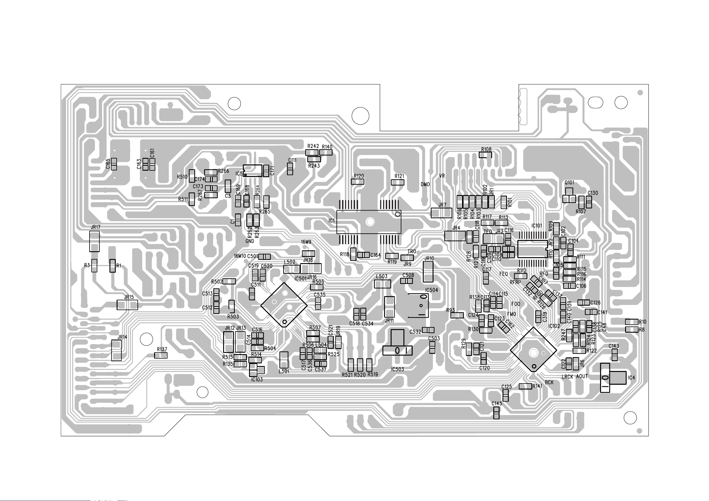
10 - 410 - 4
LAYOUT DIAGRAM - 3CDC BOARD
Page 31
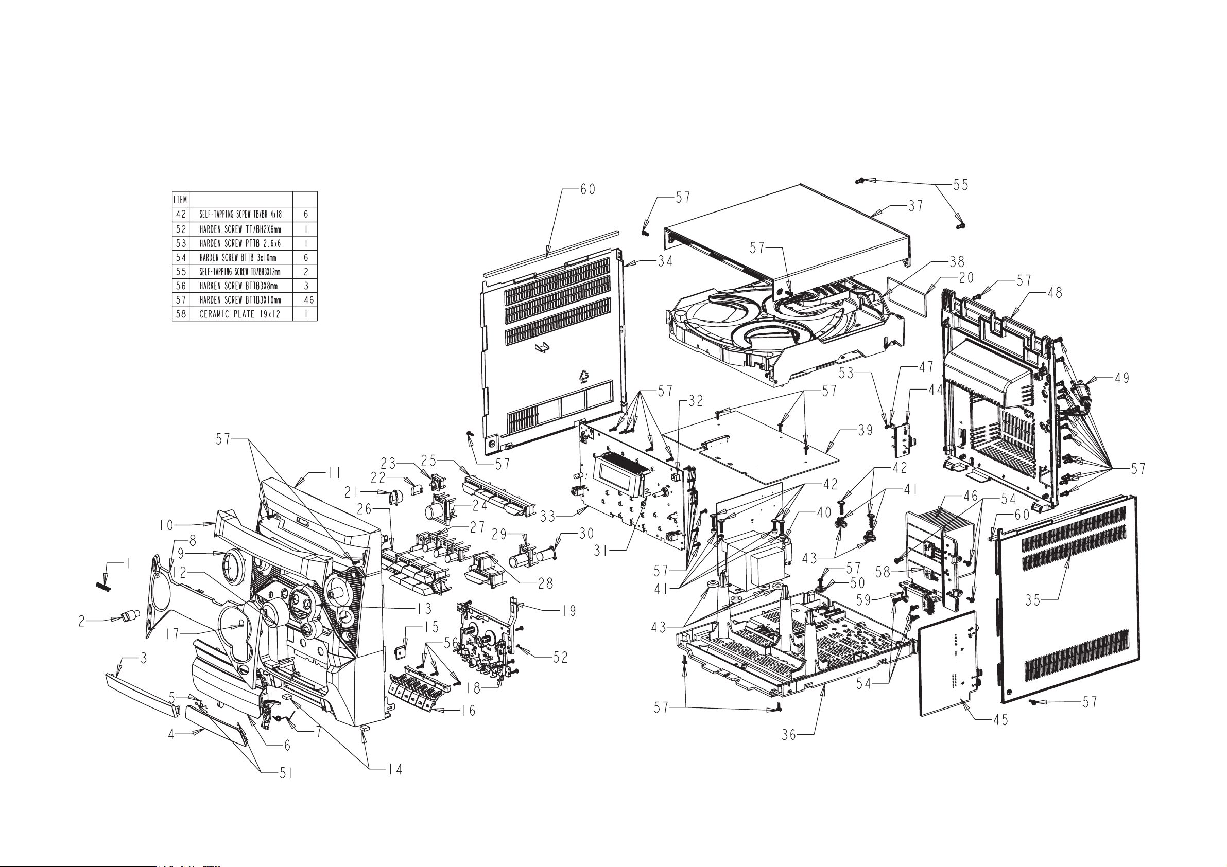
11 - 1
11 - 1
EXPLODED VIEW DIAGRAM
NAME QIT
Page 32

11 - 2
MECHANICAL PARTSLIST
2 994000004578 MIC KNOB
3 994000004584 CASSETTE DOOR LENS
4 994000004569 CASS KEYS DOOR (-/55/79)
4 994000004658 CASS KEYS DOOR (-/12)
5 994000004379 CASSETTE KEY COVER SPRING
6 994000004568 CASSETTE DOOR
7 994000001267 SPRING -RIGHT
8 994000004585 DISPLAY LENS(-/55/79)
8 994000004659 DISPLAY LENS(-/12)
9 994000004588 KEYS DECORTIVE RING
10 994000004571 3CDC DOOR
11 994000004565 FRONT CABINET (FWM352)
11 994000004661 FRONT CABINET (FWM371)
12 994000004582 VOLUME KNOB
13 994000004587 VOLUME DECORTIVE RING
14 994000001264 FOOT RUBBER
15 994000001295 DAMPER GEAR ASS'Y
16 994000004583 CASSETTE KEY WITH HOLDER
18 994000004561 F/CASS DECK CS-21SC-820DT
19 994000004586 RECORD ARM
21 994000004591 RING POWER
22 994000004579 POWER BUTTON
23 994000004589 POWER BUTTON BASE
24 994000004573 DSC BUTTON
25 994000004577 SOURCE BUTTON
ACCESSORIES
996500039002 LEFT MAIN SPK BOX (FWM371)
996500039003 RIGHT MAIN SPK BOX (FWM371)
996500039004 LEFT MAIN SPK BOX (FWM352)
996500039005 RIGHT MAIN SPK BOX (FWM352)
994000004559 REMOTE CONTROL
994000001192 AM LOOP ANTENNA
994000001381 FM ANT (BLACK) 1M
994000001478 AC PLUG ADAPTOR (not for -/12)
Note:Only these parts mentioned in the list are
normal service parts.
26 994000004575 PROGRAM KEYS
27 994000004574 CONTROL KEYS (FWM352)
27 994000004662 CONTROL KEYS (FWM371)
28 994000004576 DISC CHANGE KEY
29 994000004581 DBB BUTTON
34 994000004563 PANEL LEFT
35 994000004564 PANEL RIGHT
36 994000004567 CHASSIS PLASTIC (for -/12/55)
36 996500038608 CHASSIS PLASTIC (for -/79)
37 994000004572 TOP COVER
38 994000004562 3CDC MECHA CASING ASS'Y (FWM352)
38 994000004
48 994000004566 REAR CABINET (-/55)
48 994000004657 REAR CABINET (-/12)
48 996500038607 REAR CABINET (-/79)
49 994000004557 AC CORD BRAZIL APP 2M (-/55)
49 994000004656 AC CORD PLUG VDE 2M (-/12)
49 996500038614 AC CORD SAA APP 2M (-/79)
994000003669 CD MECHANISM DA11VF
562 3CDC MECHA CASING ASS'Y (FWM371)
Page 33

12 - 1
ELECTRICAL PARTSLIST - MAIN BOARD
- DIODES -
VD201 994000002836 VARICAP DIODE 1SV-149
VD202 994000002836 VARICAP DIODE 1SV-149
D201 994000004341 SMD DIODE BAV99L
D29 994000004363 SMD DIODE PMLL4148L
D32 994000004363 SMD DIODE PMLL4148L
D36 994000004363 SMD DIODE PMLL4148L
D37 994000004363 SMD DIODE PMLL4148L
D7 994000002446 RECTIFIER BRIDGE RS402
D8 994000004534 RECTIFIER DIODE 1N5819
- IC & TRANSISTORS -
Q11 994000004337 TRANSISTORS 2SD1936T-AC
Q12 994000004337 TRANSISTORS 2SD1936T-AC
Q22 994000004337 TRANSISTORS 2SD1936T-AC
Q35 994000004337 TRANSISTORS 2SD1936T-AC
Q6 994000004142 TRANSISTORS 9013G 1W
Q201 994000002833 TRANSISTORS 9018G
Q2 994000001193 TRANSISTORS KSB772YS
Q7 994000001193 TRANSISTORS KSB772YS
Q10 994000001193 TRANSISTORS KSB772YS
Q204 994000003937 TRANSISTORS PMBT3906
Q512 996500038609 TRANSISTORS 2W 8050C
Q36 996500038609 TRANSISTORS 2W 8050C
Q4 996500038610 TRANSISTORS 2W 8550C
U5 996500038611 IC KA7810E
U11 994000001357 IC LM78L05-AC
U1 994000001201 IC NJM4556AM
U8 994000001201 IC NJM4556AM
U12 994000001201 IC NJM4556AM
U4 994000004532 IC KA7808E (TO-220)
U14 994000004532 IC KA7808E (TO-220)
IC202 994000002843 IC TA2099N
IC201 994000002846 IC TC9257F
IC204 994000001202 IC TDA7468D
IC505 994000004533 IC YD7312
- MISCELLANEOUS -
X201 994000004535 CRYSTAL 7,2MHZ +-30PPM
CF202 994000004536 CER. FILTER SFE10,7MJA10-A 3P
CF203 994000004536 CER. FILTER SFE10,7MJA10-A 3P
CF205 994000004537 DISCRIM. FILTER JT10,7MG82-A
CF204 994000002857 CERAMIC FILTER SFU450B
CF201 994000000245 BAND PASS FILTER #GFMB3-SE
L25 994000004538 I.F.T 10148BK7
T201 994000002858 I.F.T 7mm #7M1A2186F
T202 994000002859 I.F.T 7mm #7M4A1975R
T203 994000002861 I.F.T 7mm A049
SW201 994000004539 PUSH SWITCH
RF201
994000004442
TUNER FE450-G11
Note: Only these parts mentioned in the list are
normal service parts.
Page 34

12 - 2
ELECTRICAL PARTSLIST - POWER BOARD
- MISCELLANEOUS -
C1 994000001225 SAFETY CAP 275V 0.22UF +-20% (FWM352)
C805 994000001225 SAFETY CAP 275V 0.22UF +-20% (FWM371)
L1 994000001226 FILTER INDUCTOR 400UH 3A (FWM352)
L802 994000001226 FILTER INDUCTOR 400UH 3A (FWM371)
F2 994000001229 FUSE RADIAL T200mA 250V (only for-/12)
!
F3 994000001222 FUSE RADIAL LT 2A 250V (FWM352)
F4 994000001222 FUSE RADIAL LT 2A 250V (FWM352)
F5 994000001223 FUSE RADIAL T5A 250V (FWM352)
F801 994000001351 FUSE RADIAL LT 4A 250V (FWM371)
F802 994000004599 FUSE RADIAL LT 3.15 A 250V (FWM371)
F804 994000001223 FUSE RADIAL LT 5A 250V (FWM371)
F805 994000001351 FUSE RADIAL LT 4A 250V (FWM371)
SW30 994000001323 SWITCH #SDKPA40300
!
!
!
!
!
!
!
Note: Only these parts mentioned in the list are
normal service parts.
Page 35

12 - 3
ELECTRICAL PARTSLIST - FRONT BOARD
- DIODES -
D45 994000004341 SMD DIODE BAV99L
D54 994000004341 SMD DIODE BAV99L
D35 994000004363 SMD DIODE PMLL4148L
D18 994000001234 LED LAMP 3mm
D34 994000001234 LED LAMP 3mm
- IC & TRANSISTORS -
Q15 994000004338 TRANSISTORS PMBT3904
Q16 994000004338 TRANSISTORS PMBT3904
Q18 994000004338 TRANSISTORS PMBT3904
Q37 994000004338 TRANSISTORS PMBT3904
Q24 994000003937 TRANSISTORS PMBT3906
U13 994000001201 IC NJM4556AM
U6 994000004541 IC M24C02-WMN6
U7 994000004542 IC PT6315
IC401 996500038612 IC TMP87CP23FG-6JJ1
IC3 994000002853 IC XC61FC3012MR SOT-23
- MISCELLANEOUS -
SW5 994000001243 TACT SWITCH
SW6 994000001243 TACT SWITCH
SW7 994000001243 TACT SWITCH
SW8 994000001243 TACT SWITCH
SW9 994000001243 TACT SWITCH
SW10 994000001243 TACT SWITCH
SW11 994000001243 TACT SWITCH
SW12 994000001243 TACT SWITCH
SW14 994000001243 TACT SWITCH
SW15 994000001243 TACT SWITCH
SW16 994000001243 TACT SWITCH
SW17 994000001243 TACT SWITCH
SW18 994000001243 TACT SWITCH
SW19 994000001243 TACT SWITCH
SW20 994000001243 TACT SWITCH
SW25 994000001243 TACT SWITCH
SW26 994000001243 TACT SWITCH
SW27 994000001243 TACT SWITCH
SW28 994000001243 TACT SWITCH
SW31 994000001243 TACT SWITCH
JACK1 994000004543 V/PHONE JACK
JACK2 994000004543 V/PHONE JACK
FTD1 994000004544 FTD DISPLAY
REM1 994000000325 OPTIC SENSER
VR2 994000001324 ROTARY VOLUME 20K
VR1 994000001241 ROTARY ENCODER
X1 996500038613 CRYSTAL 7.99968 MHZ +-20PPM
Note: Only these parts mentioned in the list are
normal service parts.
Page 36

12 - 4
ELECTRICAL PARTSLIST - AMP BOARD
- IC & TRANSISTORS -
U10 994000001203 IC TDA8947J/N3
Q19 994000004337 TRANSISTORS 2SD1936T-AC
Q20 994000004337 TRANSISTORS 2SD1936T-AC
Q29 994000004337 TRANSISTORS 2SD1936T-AC
Q30 994000004337 TRANSISTORS 2SD1936T-AC
Q31 994000004337 TRANSISTORS 2SD1936T-AC
Q27 994000004545 TRANSISTORS BUK9507-30B
Q28 994000004546 TRANSISTORS PBSS4140S
- MISCELLANEOUS -
D40 994000001196 BRIDGE RECTIFIER 8A GBU8D
CON43 994000004547 SPK JACK MSP-134V-05 LF
CON702 994000001221 V/RCA JACK 2P
JACK1 994000001353 COAXIAL JACK IF-01A
Note: Only these parts mentioned in the list are
normal service parts.
Page 37

12 - 5
ELECTRICAL PARTSLIST - 3CDC BOARD
- IC & TRANSISTORS -
IC5 994000004548 IC ET8211 SOP8
IC504 994000002838 IC BA15BC0FP
IC4 994000002839 IC H1117SJ-3.3V
IC503 994000002839 IC H1117SJ-3.3V
IC1 994000002842 IC MM1469PH
IC101 994000002844 IC TA2157FN
IC2 994000002845 IC TA7291S
IC402 994000002845 IC TA7291S
IC102 994000002849 IC TC94A14FAG
IC501 994000002851 IC TC94A34FG-006
IC103 994000002853 IC XC61FC3012MR SOT-23
IC105 994000004549 IC KA7805E
- MISCELLANEOUS -
X501 994000004551 CRYSTAL 16,9344MHZ +-20PPM
X101 994000004551 CRYSTAL 16,9344MHZ +-20PPM
SW1 994000004552 DETECT SWITCH
SW2 994000004552 DETECT SWITCH
SW3 994000004552 DETECT SWITCH
SW4 994000004552 DETECT SWITCH
Note: Only these parts mentioned in the list are
normal service parts.
Page 38

12 - 6
ELECTRICAL PARTSLIST
- MISCELLANEOUS -
CON8 994000004553 16P FFC CABLE L=150mm
CON21 994000004554 23P FFC CABLE L=180mm
CON30 994000004487 16P FFC CABLE L=170mm
CON13 994000004457 5P FFC CABLE L=200mm
T1 994000004555 TRANSFORMER EI66 127/240V (FWM352/55)
!
T1 994000004655 TRANSFORMER EI66 127/240V (FWM352/12)
T801 994000004602 TRANSFORMER 120/240V (FWM371/55)
T2 994000000262 TRANSFORMER EI-28AC230V (FWM352/12)
!
!
!
994000004557 AC CORD BRAZIL APP 2M (-/55)
!
994000004656 AC CORD PLUG VDE 2M (-/12)
!
996500039526 MAIN BOARD ASS'Y (FWM352/12)
994000039527 MAIN BOARD ASS'Y (FWM352/55)
994000039528 MAIN BOARD ASS'Y (FWM352/79)
994000039529 MAIN BOARD ASS'Y (FWM371/55)
994000004593 POWER BOARD ASS'Y (FWM/12)
994000004594 FRONT BOARD ASS'Y (FWM352/55)
996510000845 FRONT BOARD ASS'Y (FWM352/12)
996510000971 FRONT BOARD ASS'Y (FWM371/55)
994000004597 3CDC BOARD ASS'Y (FWM/12)
994000004595 AMP BOARD ASS'Y (FWM/12)
994000004596 AM/FM BOARD ASS'Y (FWM/12)
Note: Only these parts mentioned in the list are
normal service parts.
Page 39
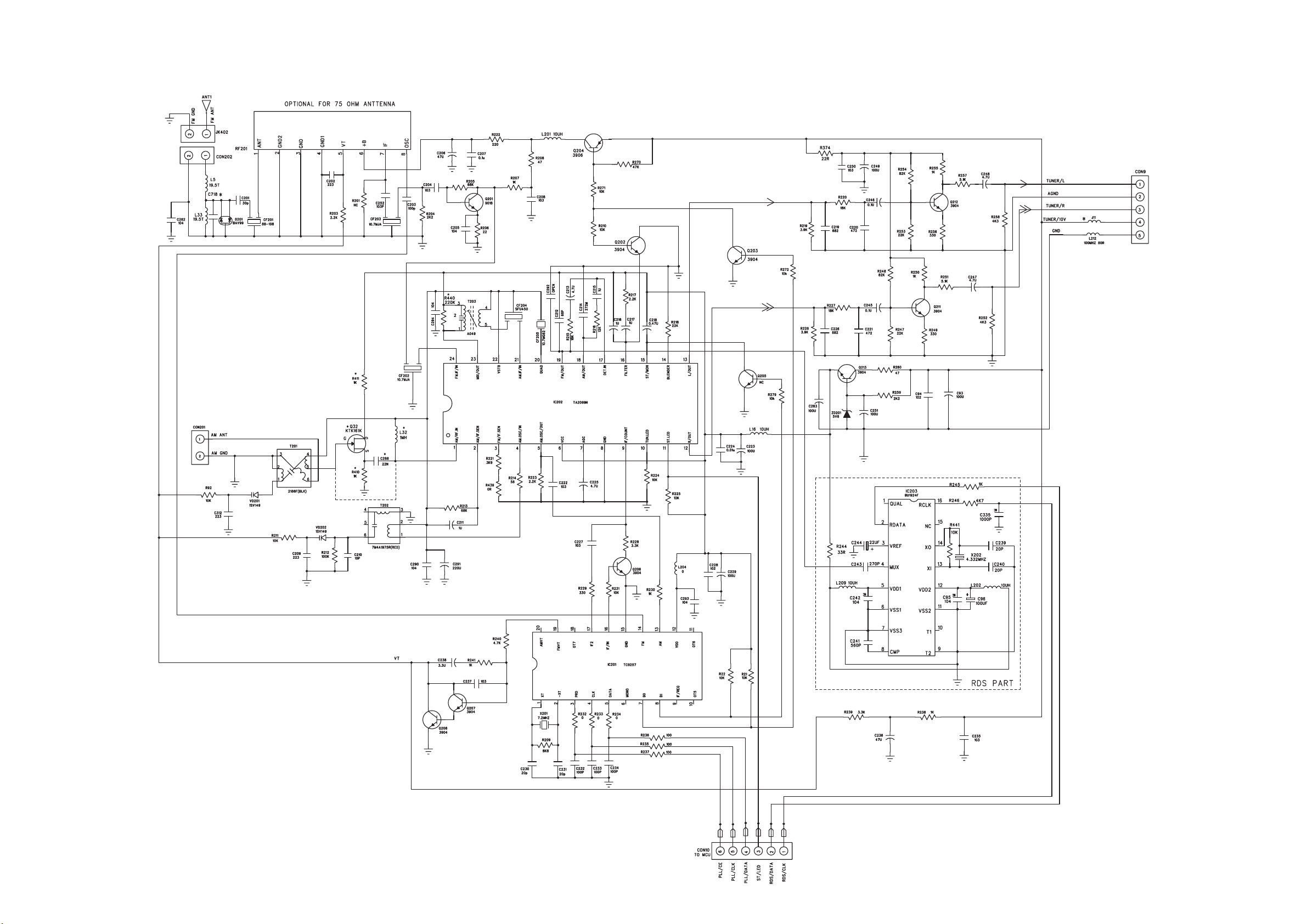
CIRCUIT DIAGRAM - MAIN BOARD
TUNER PART
13 - 113 - 1
Page 40
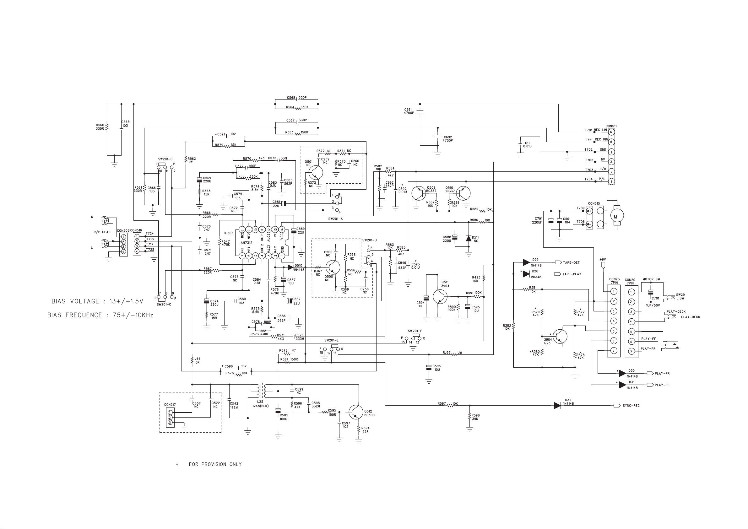
CIRCUIT DIAGRAM - MAIN BOARD
TAPE PART
13 - 2 13 - 2
Page 41
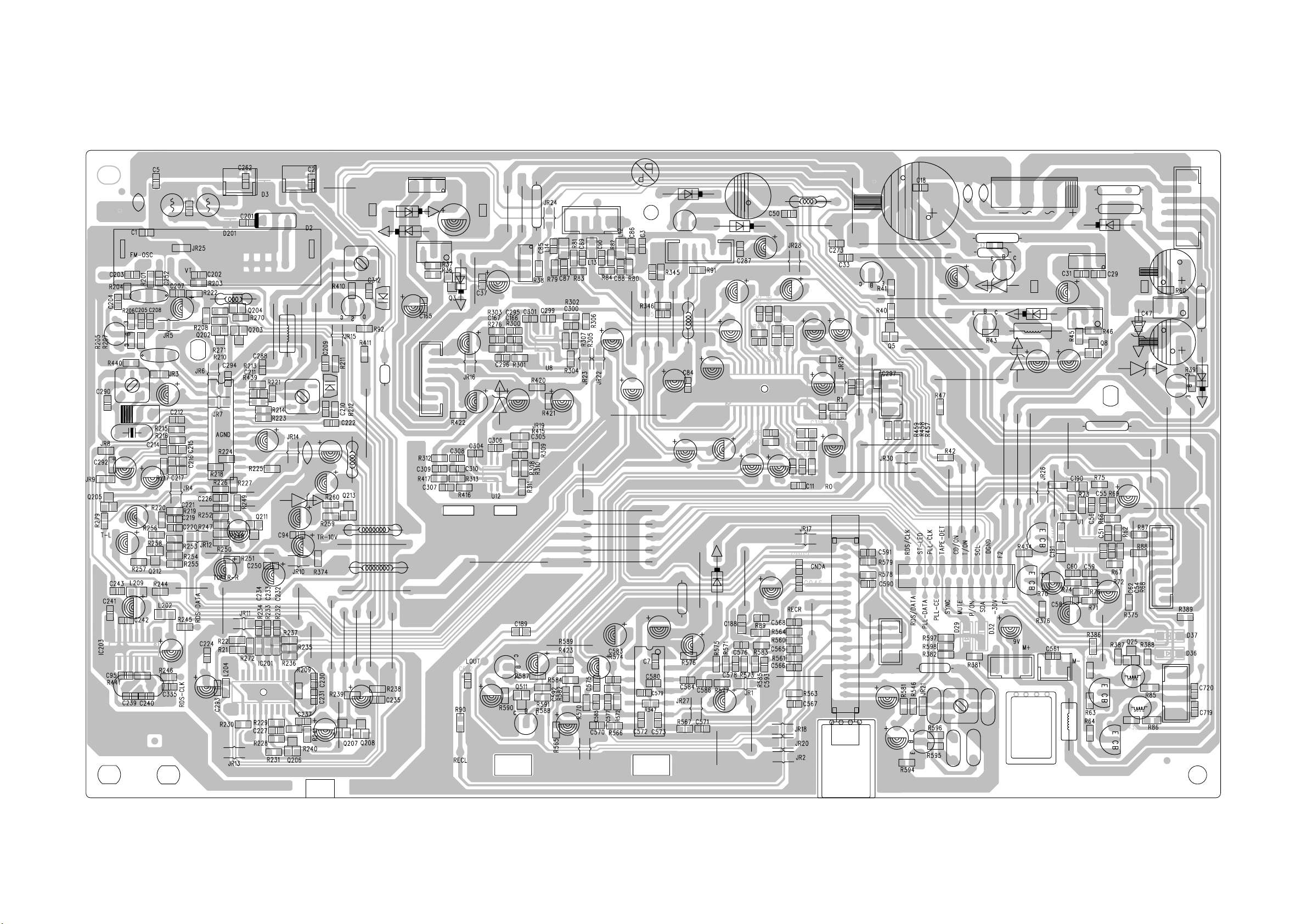
LAYOUT DIAGRAM - MAIN BOARD
13 - 313 - 3
Page 42
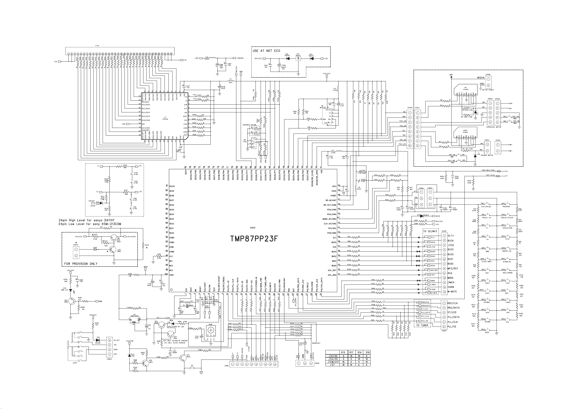
CIRCUIT DIAGRAM - FRONT BOARD
13 - 4
13 - 4
Page 43
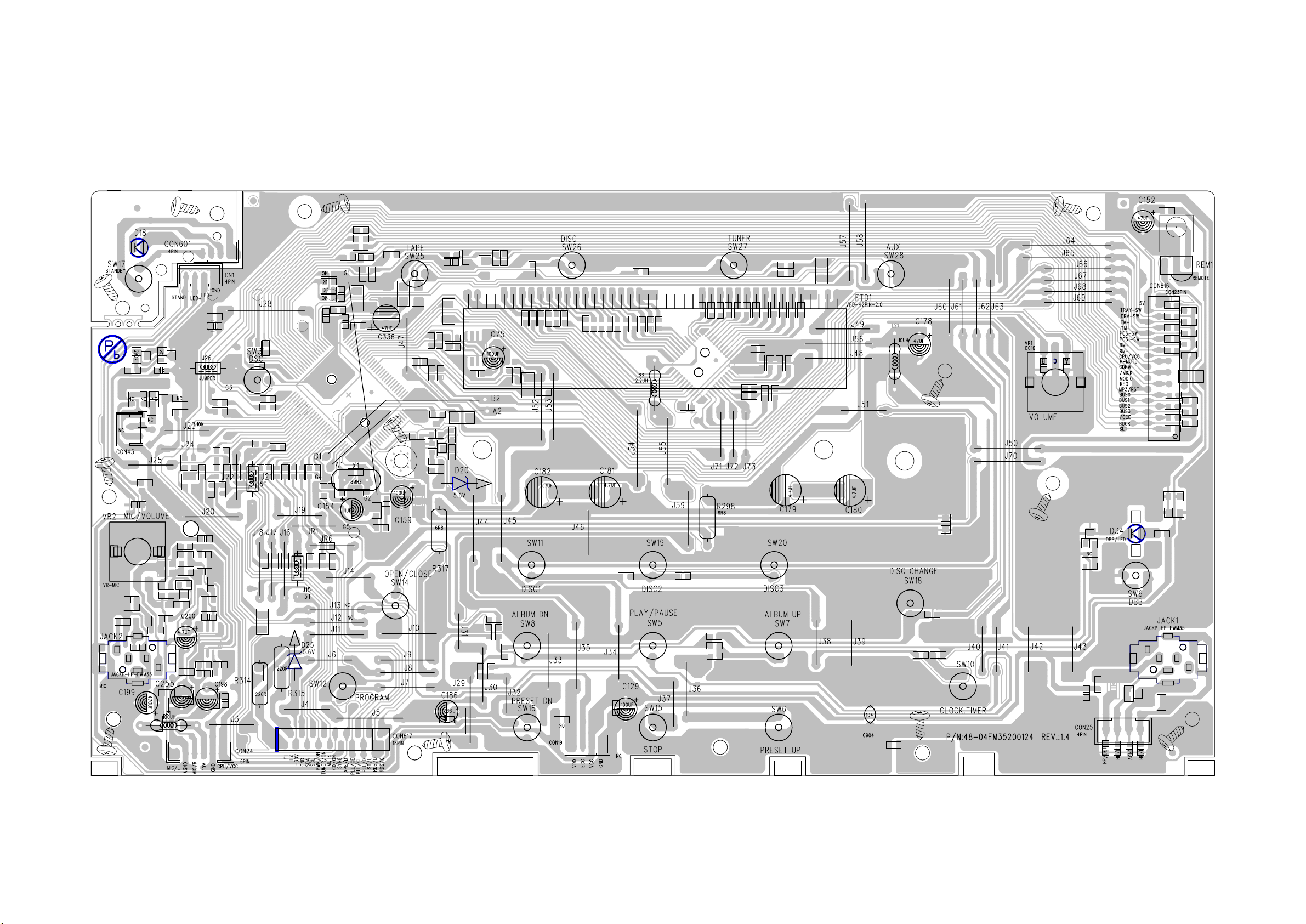
LAYOUT DIAGRAM - FRONT BOARD
13 - 513 - 5
Page 44
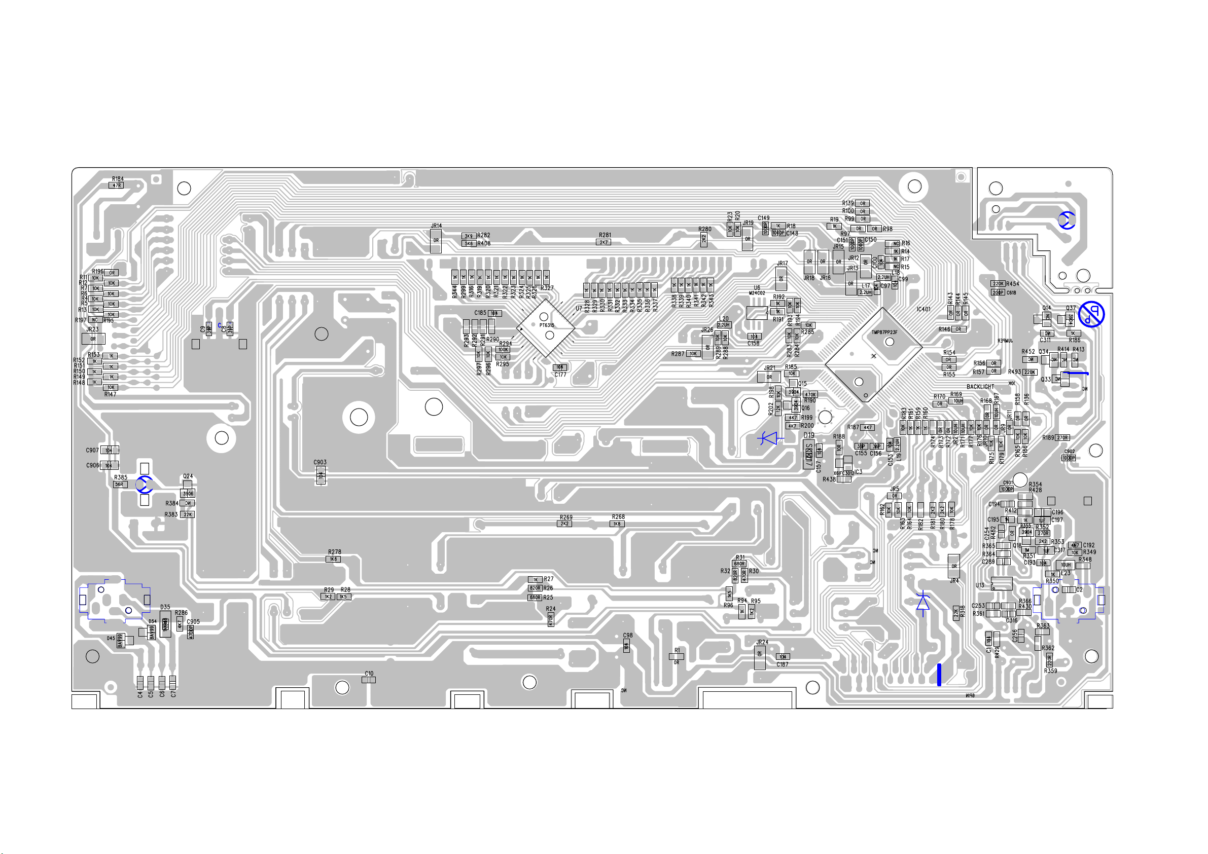
LAYOUT DIAGRAM - FRONT BOARD
13 - 6
13 - 6
Page 45

14 - 1
REVISION LIST
Version 1.0 (3141 785 30760)
- Initial Release
Version 1.1 (3141 785 30761)
- New version FWM352/79 is introduced.
- Pages 11-2 : Mechanical parts list adapted.
- Pages 12-1 and 12-6 : Electrical parts list adapted.
Version 1.2 (3141 785 30762)
- Pages 12-6 : Electrical parts list adapted.
Version 1.3 (3141 785 30763)
- Pages 13-1...13-6 : New main Board and new display board w/software v3.1
Circuit diagram and Layout diagram added.
 Loading...