

Page 1

See page 10 for
quick start
Ethernet Converter Device
FMod-TCP BOX
User Manual
Version 1.2
Page 2

2 / 58
Version: 1.2
Last revision: August 14th, 2006
Printed in Switzerland
© Copyright 2003-2006 FiveCo Sàrl. All rights reserved.
The contents of this manual may be modified by FiveCo without any warning.
Trademarks
Windows® is a registered trademark of Microsoft Corporation.
Ethernet® is a registered trademark of Xerox Corporation.
Java® is a registered trademark of Sun Microsystem.
Philips® is a registered trademark of Koninklijke Philips Electronics N.V.
Borland® is a registered trademark of Borland Software Corporation.
Warning
This device is not intended to be used in medical, life-support or space products.
Any failure of this device that may cause serious consequences should be prevented by implementation of
backup systems. The user agrees that protection against consequences resulting from device system failure
is the user's responsibility. Changes or modifications to this device not explicitly approved by FiveCo will
void the user's authority to operate this device.
Support
Web page: http://www.fiveco.ch/section_motion/support_motion_E.htm
e-mail: support@fiveco.ch
FMod-TCP User Manual v.2.8
Page 3

3 / 58
Table of Contents
1 Package and operating conditions .................................................................................................................5
Starter Kit contents ................................................................................................................................................5
Absolute maximum rating..................................................................................................................................5
2 Overview......................................................................................................................................................................6
Applications.................................................................................................................................................................6
Software operating principle.............................................................................................................................6
Hardware description...........................................................................................................................................7
SOS button .................................................................................................................................................................9
3 Quick start ................................................................................................................................................................10
Changing IP address ............................................................................................................................................10
4 Controlling the FMod-TCP BOX by TCP or UDP..........................................................................12
General Information............................................................................................................................................12
RS232 (TCP # 8000).........................................................................................................................................12
Device parameters and I/O, A/D and I2C features (TCP # 8010 or UDP # 7010).13
Easy IP address config (UDP # 7010)......................................................................................................19
Checksum calculation.........................................................................................................................................20
5 Java Applet................................................................................................................................................................22
Overview...................................................................................................................................................................22
Main Config..............................................................................................................................................................23
Test A/D and I/Os ...............................................................................................................................................24
Test RS232 ...............................................................................................................................................................25
Test I2C......................................................................................................................................................................26
6 Win32 Application...............................................................................................................................................28
Overview...................................................................................................................................................................28
RS232 interface......................................................................................................................................................30
“Load web files” interface................................................................................................................................31
Main port interface..............................................................................................................................................32
7 Registers management.......................................................................................................................................34
Memory Organization........................................................................................................................................34
Full Register Description...................................................................................................................................35
FMod-TCP User Manual v.2.8
Page 4

4 / 58
Revision history
Revision Date Author Note Firmware
version
1.0 05.05.06 AG - First version Since 1.0 Since 1.0 Since 3.0
1.1 09.06.06 AG - Update specifications
- Text corrections
1.2 14.08.06 AG - I2C speed correction.
- Warning register bits correction.
Since 1.0 Since 1.0 Since 3.0
Since 1.0 Since 1.0 Since 3.0
Applet
version
Win32 app
version
FMod-TCP User Manual v.2.8
Page 5

1 Package and operating conditions
Starter Kit contents
The FMod-TCP BOX “Starter kit” should contain:
FMod-TCP BOX device
RS232 DSub cable
DIN 41651 40 lines cable
CD-Rom with dedicated software and Java applet sample
This manual
Absolute maximum rating
Damage may occur if the device is operated using values beyond those
mentioned below; device operation is not guaranteed.
Parameter Conditions Min Typ Max Unit
Supply voltage 0 24 33 V
Supply current No device connected to extension
connector.
Supply current Device(s) connected to extension
connector.
Outputs 1, 2 current Relays. 1 A
Outputs 1, 2 voltage Max voltage to GND. 50 V
Preliminary
Outputs 3-14 current 0.5 A
Outputs 15, 16 current 1 A
Inputs voltage -15 28 V
+5V output current Pin 17 on extension connector. 0.4 A
Power output current Pin 40 on extension connector. 1 A
Operating temperature 0 70 °C
Storage temperature -40 120 °C
All external pins are protected against destruction by ESD (2kV).
The power supply input is protected against over and inverted voltage by a
33V Zener diode. The protection is guaranteed during 10ms within the
following current values:
For inverted voltage: 100A (the internal polifuse will cut the supply).
For over voltage: 3.25A max (the diode will be destroyed before the
fuse after 10ms!).
Damages to the device due to over or inverted voltage are not covered by
the warranty.
5 / 58
60 100 mA
3 A
FMod-TCP User Manual v.2.8
Page 6

2 Overview
Applications
The FMod-TCP BOX is a TCP/IP server that allows system integrators to
connect different devices such as home appliances, industrial sensors and
industrial control systems directly to the Ethernet network, (10BaseT) and to
remotely monitor and control those using standard protocols.
It can either be accessed through a TCP socket connection, from a
computer, or through a simple Web Page in a standard browser which can
be directly loaded to the device (max 44kb). The module is delivered with a
default web page including a Java Applet that enables the controlling of the
device.
The connection between this device and the user's product can be done
through the following interfaces:
Qty Type Description Port
1 RS232 Up to 115200 bps with or without
2 Relays Cut up to 50V 1A
14 24V Outputs High side drivers
16 24V Inputs Digital 24V inputs or analog ±12 V
1 I2C bus 2 wires bus serial bus
Note:
Some examples of applications illustrating the use of the FMod-TCP family
with serial, I2C, I/O and A/D devices can be found on the FiveCo's
website: http://www.fiveco.ch/section_motion/tcp_db/real_tcp_E.htm
hardware flow control
10 bits A/D
6 / 58
TCP 8000
TCP 8010
UDP 7010
Software operating principle
The operating principle for PC softwares that must exchange data with an
FMod-TCP BOX device depends on which interface is used.
In case of RS232 use, the operation is really simple. Any byte sent to port
TCP #8000 will be redirected to the serial bus and any byte received from
the serial bus will be redirected to the TCP connection.
In the other cases (I/O, A/D and I2C), the software has to use a dedicated
protocol layer on top of the TCP Layer (see chapter 4). This protocol is
FMod-TCP User Manual v.2.8
Page 7

"Question & Answer" oriented. The PC should send a Question, wait for the
Answer and so on.
To configure the device's parameters and to access I/O and A/D features,
the protocol uses an Internal Registers Access routine (see chapter 4 and 7).
The code samples available on the FiveCo's web site can help programmers
get started with development.
Hardware description
Power connector
12 – 32 VDC
7 / 58
Inputs, Outputs, I2C bus,
Supply voltage, 5V and GND
Beware:
Before connecting any cable to the device, shut down power supply!
Front view
RS232 connector
Dimensions in mm
Ethernet connector SOS button
RJ45 Ethernet connector SOS button
FMod-TCP User Manual v.2.8
Page 8
8 / 58
See page 9 to know how the SOS button works.
Two LEDs illuminate the SOS button and the displayed color as the
following meanings:
Green Everything is normal.
Red There is an error. See Warning register to know the
source of the error.
Red-Green The device found another one with the same IP address
blinking on the network. Disable the oth o
FMod-TCP BOX.
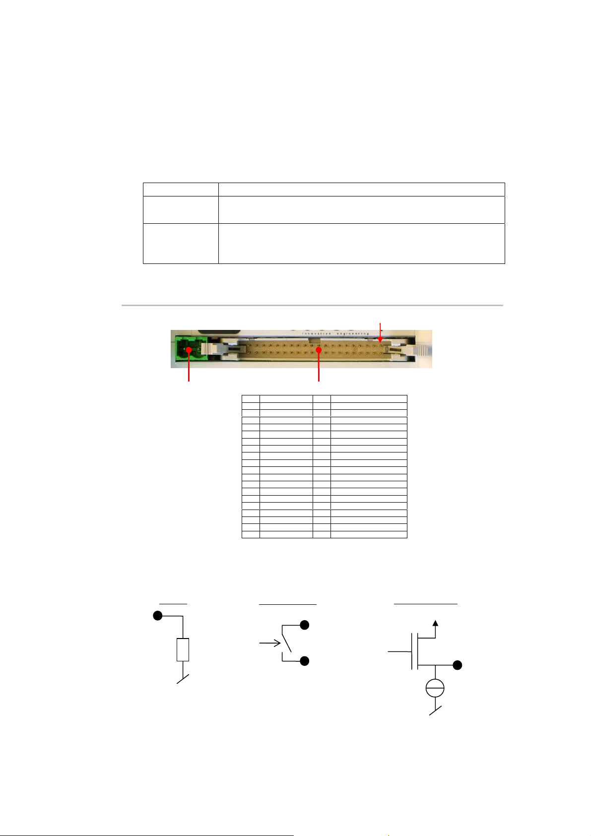
Left side
er device and rebo t the
1st pin
Power connector
12 – 32 VDC
Here are the equivalent electrical specif s of I/O pins (illustra
Inputs, Outputs, I2C, Supply voltage, 5V and GND
1 Input 1 21 Output 16
2 Input 2 22 Output 15
3 Input 3 23 Output 14
4 Input 4 24 Output 13
5 Input 5 25 Output 12
6 Input 6 26 Output 11
7 Input 7 27 Output 10
8 Input 8 28 Output 9
9 Input 9 29 Output 8
10 Input 10 30 Output 7
11 Input 11 31 Output 6
12 Input 12 32 Output 5
13 Input 13 33 Output 4
14 Input 14 34 Output 3
15 Input 15 35 Output 2 B (relay 2)
16 Input 16 36 Output 2 A (relay 2)
17 +5V 37 Output 1 B (relay 1)
18 GND 38 Output 1 A (relay 1)
19 I2C clock (SCL) 39 Supply GND
20 I2C data 40 Supply voltag
a
Do not supply the device throu s r connector.
(SDA) e (max 1A) a
gh thi pin. Use powe
ication ted by
black dots):
Inputs
Outputs 1-2
Outputs 3-16
A
~47kΩ
Preliminary
B
V
power
2mA
FMod-TCP User Manual v.2.8
Page 9

9 / 58
The I2C pins are provided through a Philips PCA9512 driver chip. 10kΩ
pull
-ups are connected to A.
SCL and SD
ht side
Rig
The RS232 connector is the same as the ones found on any computer.
SOS button
A button is dedicated to restore default IP address or factory settings.
There are tow possible scenarios:
If you press it while the device is running, the IP address will be
If the button is pressed during startup, the default IP address
Standard RS232 DSub 9 connector
(male like on a computer)
r l TC tions a
estored as soon as al P connec re closed. Warning: you
have to send the Save Settings command to the device in order to save it
into EEPROM.
factory settings of all parameters will be restored AND saved into
EEPROM. In this case, you do not need to send the Save Parameters
command.
1 NC 6 NC
2 Receive data 7 Request To Send
3 Transmit data 8 Clear To Send
4 NC 9 NC
5GND
and
FMod-TCP User Manual v.2.8
Page 10

3 Quick start
This section is intended to help users to quickly plug the module into their
system and establish a connection between the computer and the device.
You can find the device’s factory communication settings on the following
label.
The Ethernet MAC Address is fixed and cannot be changed. The IP Address
can be changed. The complete procedure is described below.
Note: If the device has already been configured and the IP address has been
changed to an unknown value, you can retrieve an SOS IP address (the one on
label) by pressing the “SOS button” during the normal operation of the device.
(See section Erreur ! Source du renvoi introuvable.).
FMOD-TCP BOX
INPUT(supply) : 5-32V DC, max 3A
MAC: 00-50-C2-30-xx-xx / IP : 169.254.5.5
This device is not intended to be used in a medical, life-support or space product. Any failure
of this device that may cause serious consequences should be prevented by implementation
of backup systems. The user agrees that protection against consequences resulting from
device system failure is the user's responsibility. motion@fiveco.ch / www.fiveco.ch
10 / 58
Changing IP address
To easily change the factory IP address, use the Win32 software provided on
the CD-Rom.
1. Plug your new device on your PC network.
2. Start the Win32 application.
3. Click on "File->Easy change IP address".
4. The software will scan the network and display a list of all FiveCo's
devices found.
5. Select the MAC address corresponding to your new device.
6. If you have more than one network adapter on your PC, the
software will ask you to select the one which is connected to the
same network as the FMod-TCP BOX.
7. The software will suggest a new IP address with the last byte left
open. Choose a new IP (Not already used on your network!!) and
click the "Change IP address" button.
That’s it! The device has a new address and a new subnet mask (the same as
your PC). They are automatically saved into EEPROM.
FMod-TCP User Manual v.2.8
Page 11

11 / 58
You can now connect the device with the Win32 software or open its web
page by typing its new IP address into a web browser.
Notes:
The IP address won't be changed if a TCP connection exists with the
device.
The protocol used to change the IP address is described later in this
manual.
FMod-TCP User Manual v.2.8
Page 12

4 Controlling the FMod-TCP BOX by TCP or UDP
General Information
All the device's parameters (configuration registers) and features can be
accessed through a TCP or UDP port.
In addition, an HTTP-TCP port is available for web pages downloading and
another TCP port for RS232 bus access.
Those ports are:
TCP Port #80 for HTTP communication.
TCP Port #8000 for RS232 transceiver.
TCP Port #8010 to access I/O registers (see chapter 7) and I2C bus.
UDP Port #7010 to access I/O registers (see chapter 7) and I2C bus.
With regards to TCP connections, the device allows up to 4 simultaneous
connections.
These ports are described below.
12 / 58
RS232 (TCP # 8000)
The RS232 bus of the microcontroller is accessible through the TCP port
number 8000. The module acts simply as a transceiver for this port. Any
byte sent from the network (ex: TCP-IP from a PC) to the module will be
sent to the other side’s RS232 bus, and vice versa. Thus there is no particular
protocol dedicated to this feature. See later chapters to know how to
change parameters such as baud rate and hardware flow control.
Note: This port supports only one user at a time.
RS232 fixed settings:
Important note about baud rate greater than 9600bds:
Common TCP/IP stacks (on PC, Unix station …) use a delay of 200ms for
the acknowledgement of the TCP received data packets. This is done to
reduce traffic on the network because TCP allows the acknowledgement of
several packets at one time.
Unfortunately, the FMod-TCP BOX device needs this acknowledgement to
remove the data from its internal RS232 receive buffer (if no acknowledge is
received from the PC, the module will resend those data).
No parity / 1 Start Bit / 8 Data Bits / 1 Stop Bit
FMod-TCP User Manual v.2.8
Page 13

13 / 58
So, with speeds greater than 9600bds, the buffer may be filled faster than
data can be sent by TCP and part of those will be lost if no RS232 hardware
flow control is used between the FMod-TCP BOX and the RS232 device
(CTS and RTS lines).
If you cannot use hardware flow control on RS232 bus and you have to get
more than 2048 bytes at one time, the solution is to reduce the TCP
acknowledgement delay on your computer.
For WindowsTM 2000/XP users, you can add/change the following value in
the registry. BEWARE: improperly changes done in the Windows registry can
results in a system crash! Such changes are the user’s full responsibility!
Entry:
Key:
Value:
The interface-name is the registry name (32 digits number) of your Ethernet
card which you use to access the module.
The following web page describes this feature in details:
http://www.microsoft.com/resources/documentation/Windows/2000/server/reskit/enus/regentry/58801.asp?frame=true
HKey_Local_Machine\SYSTEM\CurrentControlSet\Services\
Tcpip\Parameters\Interfaces\Interface-name
TcpDelAckTicks
DWORD with value 0x00
Device parameters and I/O, A/D and I2C features (TCP # 8010 or UDP # 7010)
The main TCP port number 8010 or UDP port number 7010 can be used
to change some important parameters of the module:
TCP timeout value
IP address
Subnet mask
Module name
Baud rate and flow control
I2C speed
The user should use the Win32 application enclosed in the package or the
default java applet loaded in the module to change those parameters. If the
user wants to change the parameters by himself, the protocol is defined
below.
This port is also used to access Inputs and Outputs value, A/D conversion
result registers (see page 34 for a complete description of those registers)
and I2C bus. The I2C feature is described after “registers access feature”.
The last feature accessible through this port is the "Easy IP config" that is used
in the "Quick start" chapter of this document.
FMod-TCP User Manual v.2.8
Page 14

14 / 58
Registers access feature
TCP/IP works in big endian: most significant byte first, followed by least
significant byte.
The access to the data is done through an easy (6 byte header) protocol
over TCP.
Structure of each packet:
1. Function ID (2 bytes),
2. Transaction ID (2 bytes)
3. Length of the parameters (2 bytes)
4. Parameters (X byte)
5. Checksum (2 bytes) (described later in this chapter)
The user (sender) defines the values of the Transaction IDs himself. The
module that receives a command sends back an answer (for every
command). The answer contains the same Transaction ID as the
corresponding command sent. The user is also able to check execution of
each command.
Read register(s) command:
Byte# Number of bits Example
0x00 Read (0x0021) 16 bits 0x0021
0x02 TransactionID 16 bits 0x1B34
0x04 Number of registers to
16 bits 0x0001
read (X)
0x06 X * Registers Addresses X * 8 bits 0x02
0x06+X Checksum 16 bits 0x…
The maximum number of registers that can be read at one time is almost
30. The answer sequence should not be greater than 180 bytes. If the
number of registers is too big, the FMod-TCP BOX will answer only with the
value of some of them.
The module answers with the following sequence:
Byte# Number of bits Example
0x00 Read Answer (0x0023) 16 bits 0x0023
0x02 TransactionID (same as
demand)
0x04 Number of bytes in answer 16 bits 0x0019
0x06 Register address 8 bits 0x02
… Register value 8—128 bits (16B) 0x12345
16 bits 0x1B34
The two previous entries are replicated for every register that has been asked for reading
… Checksum 16 bits 0x…
FMod-TCP User Manual v.2.8
Page 15

15 / 58
p
p
RAAddR
ABy
Write register(s) command:
Byte# Number of bits Example
0x00 Write (0x0022) 16 bits 0x0022
0x02 TransactionID 16 bits 0x1B34
0x04 Number of bytes in
16 bits 0x0003
command
0x06 Register Addresses 8 bits 0x02
0x07 Register value 8 — 64 bits 0x1234
The two previous entries are replicated for every register that has been asked for reading
… Checksum 16 bits 0x…
The max length of this sequence is 180 bytes.
The module answers with the following sequence:
Byte# Number of bits Example
0x00 Write Answer (0x0024) 16 bits 0x0024
0x02 TransactionID (same as
16 bits 0x1B34
demand)
0x04 0x0000 16 bits 0x0000
0x06 Checksum 16 bits 0x…
I2C feature
The Inter-IC bus, commonly known as the I²C bus, is a control bus that
provides the communications link between integrated circuits in a system.
Developed by Philips in the early 1980’s, this simple two-wire bus has
become the de facto worldwide standard for system control, finding its way
into everything from temperature sensors and voltage level translators to
EEPROMs, general-purpose I/O, A/D and D/A converters, CODECs, and
microprocessors of all kinds.
You can find the I2C’s specifications on the Philips web site at the following
link: http://www.semiconductors.philips.com/
The I2C protocol can access a device by three different manners:
Write (Start, AddW, Byte1, Byte2, …, Stop)
St AddW A Bytes to WAS
Read (Start, AddR, Byte1, Byte2, …, Stop)
St AddR A Bytes to RnA S
Read After Write (Start, AddW, ByteW1, ByteW2, …, ReStart,
AddR, ByteR1, ByteR2, …Stop)
St AddW A Bytes to W
tes to R nA Sp
FMod-TCP User Manual v.2.8
Page 16

16 / 58
To be able to do all of these 3 sequences, use this command:
Byte# Number of bits Example
0x00 I2CRWwithAck (0x0007) 16 bits 0x0007
0x02 TransactionID 16 bits 0x1B34
0x04 LengthOfParameters (X + 3) 16 bits 0x0005
0x06 7 bits Address (bit 7 = 0) 8 bits 0x28
0x07 X (number of bytes to write) 8 bits 0x02
0x08 xBytes X bytes 0xAF1D
…. Y (number of bytes to read) 8 bits 0x05
The four previous entries can be replicated to access the same or other I2C slaves within this
command sequence.
Checksum 16 bits 0x…
If X = 0, the Read method is used.
If Y = 0, the Write method is used.
If X & Y ≠ 0, the Read after Write method is used.
The answer sequence is the following one:
Byte# Number of bits Example
0x00 I2CReadAnswer (0x0008) 16 bits 0x0008
0x02 TransactionID (same as
demand)
0x04 Number of bytes in answer 16 bits 0x0005
0x06 Answer bytes Y bytes 0x1A25…
… Ack state of the I2C com. 1 byte 0x87
If the same or other I2C slave have been accessed in the command, the answer bytes and ack
state is added here.
… Checksum 16 bits 0x…
The "Ack state" byte is composed of the following bits:
0 Address ack in write sequence 0 = No answer to this address
1 Bytes written ack (each byte was acked) 0 = Bytes not acknowledged
2 Address ack in read sequence 0 = No answer to this address
3-6 Reserved 7 Must be always 1 1
The user can use these bits to check for the presence of his I2C devices and
monitor hardware issues.
16 bits 0x1254
1 = ack received
1 = ack received
1 = ack received
FMod-TCP User Manual v.2.8
Page 17

17 / 58
Note that the max length of those sequences is 180 bytes. Pay close
attention to building sequences that do not exceed this and not to ask too
much byte in answer !
The FMod-TCP BOX translates automatically those sequences to I2C
sequences. It is mandatory that the sequence has to be transmitted within
one TCP packet. Otherwise, the FMod-TCP BOX will ignore it.
I2C Bus scanning
The following command allows user to ask an I2C bus scanning to list which
addresses answer with an acknowledge.
I2C scan command:
Byte# Number of bits Example
0x00 I2CScan (0x0005) 16 bits 0x0005
0x02 TransactionID 16 bits 0x2001
0x04 Number of addresses to scan 16 bits 0x0001
0x08 X Addresses X bytes 0x1A
Checksum 16 bits 0x…
The FMod-TCP BOX answers with the following sequence:
Byte# Number of bits Example
0x00 I2CScanAnswer (0x0006) 16 bits 0x0006
0x02 TransactionID (same as
demand)
0x04 Number of valid addresses 16 bits 0x0001
0x06 Valid addresses list n bytes 0x1A
Checksum 16 bits 0x…
Note:
If there is no address in the I2C Scan command, the FMod-TCP BOX will
scan all addresses between 1 and 127!
16 bits 0x2001
I2C speed change (advanced features)
The I2C bus speed can be changed at any time by changing the content of
the I2CSPD parameter.
Beware:
1. Do not change I2C speed if it is not mandatory. Speed greater than
100kHz are not supported by all I2C slaves.
2. Do not change I2C speed during I2C communication.
FMod-TCP User Manual v.2.8
Page 18

18 / 58
3. The I2C controller does not match all I2C specifications at speed
higher than 100kHz. This feature will therefore not work with all I2C
slaves.
The value of the I2CSPD parameter must be computed with the following
formula:
7
2
CSPDI
10
2
CSpeedI
wanted
The I2C speed cannot be saved in EEPROM.
1
−=
FMod-TCP User Manual v.2.8
Page 19

Easy IP address config (UDP # 7010)
A really useful feature of the UDP port #7010 is the "Easy IP config" one.
The user who wants to design his own software can use this feature to do a
"quick start/install" method. Indeed, since this protocol uses a broadcast UDP
packet, even if the device is not in the same subnet, it should receive its new
IP address and subnet mask.
Procedure:
Send a UDP broadcast message (using a local or direct broadcast IP address)
to your network (inside which the FMod-TCP BOX is connected) with the
following command:
Byte# Number of bits Example
0x00 Change IP fct (0x002A) 16 bits 0x002A
0x02 TransactionID 16 bits 0x0000
0x04 Length of params (0x000E) 16 bits 0x000E
0x06 FMod-TCP BOX Mac Address 6 bytes 0x0050C2308101
0x0C FMod-TCP BOX new IP
Address
0x10 FMod-TCP BOX new
SubnetMask
0x14 Checksum 16 bits 0x…
If the FMod-TCP BOX recognizes its MAC address, it will answer this
command with a simple acknowledges and change its IP address and subnet
mask IF NO TCP CONNECTION IS MADE TO THE DEVICE.
Byte# Number of bits Example
0x00 Change IP fct ack (0x002B) 16 bits 0x002B
0x02 TransactionID 16 bits 0x0000
0x04 Length of params (0x0000) 16 bits 0x0000
0x14 Checksum 16 bits 0x…
19 / 58
4 bytes 0xC0A81064
4 bytes 0xFFFF0000
FMod-TCP User Manual v.2.8
Page 20

Checksum calculation
This checksum is the same as the IP checksum.
Definition: sum of 1’s complement of all 16 bits words of whole message
(FiveCo packet) except checksum bytes.
Note: all values are unsigned!
Sequence:
1. Clear accumulator
Loop
x. Only if last word is not made of two bytes, the data byte is the upper byte (big endian)
2. Compute 1’s complement of each 16bits word, result is 16bits
3. Convert last result from 16 bits to 32 bits, result is 32bits: 0x0000+last result
4. Add last result to the 32 bits accumulator
Try the Loop
5. Convert accumulator in two 16bits words
6. Add those two 16bits words, result is 16bits word.
7. If an overflow occurs with the last addition (Carry), add 1 to the last result.
8. Last result is the final result
Example (in hexadecimal):
!0x0021 (0XFFDE) Æ 0x0000FFDE (Read)
+!0x1234 (0xEDCB) Æ 0x0001EDA9 (TransID)
+!0x0003 (0xFFFC) Æ 0x0002EDA5 (3 reg to read)
+!0x0A10 (0XF5EF) Æ 0x0003E394 (reg 0A,10,02)
+!0x02(00)(0XFDFF) Æ 0x0004E193
Note that in this case a last 00 is implicitly used. (02 Æ 02 00).
0x0004 + 0xE193 = 0xE197, (carry=0)
0 xE197 + carry = 0xE197
20 / 58
Checksum = 0xE197
FMod-TCP User Manual v.2.8
Page 21

21 / 58
Here is an example of a checksum calculation function in C:
int RetCheckSum(Byte* ByteTab, int Size)
{
// This function returns the calculated checksum
unsigned int Sum=0;
bool AddHighByte=true;
unsigned int ChecksumCalculated;
for(int i=0;i<Size;i++)
{
if(AddHighByte)
{
Sum+=((ByteTab[i])<<8)^0xFF00;
AddHighByte=false;
}
else
{
Sum+=(ByteTab[i])^0x00FF;
AddHighByte=true;
}
}
if (AddHighByte==false)
Sum+= 0xFF;
ChecksumCalculated = ((Sum>>16)&0xFFFF)+(Sum&0xFFFF);
ChecksumCalculated = ((ChecksumCalculated>>16)&0xFFFF)
+(ChecksumCalculated&0xFFFF);
return ChecksumCalculated;
}
This function needs a Byte array (ByteTab) containing the command
sequence and this array’s length (Size) as input, it returns the checksum as an
int.
FMod-TCP User Manual v.2.8
Page 22

5 Java A pplet
A specific Java Applet is provided with the module to control any of its ports
without having to write any specific code.
Overview
To connect to the http server on the device, simply open your web browser
and type the IP address of the module. Example with default address:
“http://169.254.5.5”
The applet is downloaded from the device to your computer and runs as a
local process (on your computer). You need to use an internet web
browser that is compatible with Java 1.1.
Please note that on an MSWindows
occur when you download the applet due to an MSWindows
The navigation through the four panels of the applet is done through the
menu bar:
22 / 58
TM
based computer, a few seconds delay can
TM
NetBios issue.
FMod-TCP User Manual v.2.8
Page 23

Main Config
23 / 58
The Main panel shows the general information related to the device.
• The first part allows the user to change the main settings of the device.
Don't forget to use the "Save user parameters" button to make changes
permanent!
• The second part allows the user to save/restore user and factory
parameters and to read the actual configuration of the device if it has been
modified by another application.
FMod-TCP User Manual v.2.8
Page 24

Test A/D and I/Os
This page can be used to access Inputs state and voltage and change Outputs
state.
The Inputs state and voltage are regularly updated automatically (20 kHz).
You can change the low to high threshold of the inputs between 0 and 24V.
This page display also the device supply voltage and warnings (Too low/high
supply voltage, Outputs driver over current or temperature).
24 / 58
FMod-TCP User Manual v.2.8
Page 25

Test RS232
25 / 58
This page can be used to access RS232 bus.
If you click on the "Connect to RS232 TCP Port" you can send ASCII data to
RS232 bus and receive data from it (only ASCII is visible in this application).
You can check "Add LF", "Add CR" and/or "Add Null" boxes to add a Line
Feed, a Carriage Return and/or a Null Byte at the end of the ASCII chain
sent to the device.
FMod-TCP User Manual v.2.8
Page 26

26 / 58
Test I2C
This page can be used to access I2C bus.
The panel is divided in two parts:
The part on the right allows scanning the I2C bus to find available
slave devices.
The part on the left allows sending a read or a write command to a
device on the I2C bus.
You should first check if you want a read or a write. Then you have to write
hex data to write to the device in the "Hex data to write" field (if you
FMod-TCP User Manual v.2.8
Page 27

27 / 58
checked the "Read" box, the FMod-TCP BOX will use the read after write
I2C feature).
After writing the I2C address (7bits hexa) and the number of bytes to read
(if applicable), click on the "Send" button. The answer is displayed in hex in
the "Data received" field.
FMod-TCP User Manual v.2.8
Page 28

6 Win32 A pplication
A specific application is provided with the module to control any of its ports
without having to write a specific code.
Overview
IP address of
the module
TCP port
number
28 / 58
Open or
close TCP
port
Connection
status
Depends
on port
To open a TCP port on the module, the user has to set the correct IP
address of the module, to choose the correct TCP port in the list and to
click on the "Open" button. To close the port, simply click on the "Close"
button.
The status bar displays the status of the connection:
Connected
Disconnected
Error of connection (if connection was not established within 30s)
Note: If you forgot the IP address of the module, you can use the "Scan network"
feature of the "Connection" menu.
FMod-TCP User Manual v.2.8
Page 29

29 / 58
This application uses the IP address of your computer and its subnet mask to
find the scan broadcast address. When you click on scan, a broadcast
message will be sent to all devices in your subnet and answers will be listed.
WARNING: it only works with devices in your subnet!
How does it work?
When you click "Scan", the software simply sends a "Read registers"
command to a broadcast address on UDP port number 7010 (see chapter
about main port at page 13).
The broadcast address depends on the network subnet mask present on
your PC.
FMod-TCP User Manual v.2.8
Page 30

RS232 interface
30 / 58
chain to
send
Send
ASCII, Hex,
or Decimal
chain
Bytes received
from RS232
The RS232 interface is easy to use. Just write the ASCII, HEX or decimal
string in the dedicated text box and click corresponding "Send" button. The
received bytes are displayed into the "Data received" boxes (same data but
different representation).
FMod-TCP User Manual v.2.8
Page 31

“Load web files” interface
31 / 58
List of files to
load
File(s) list
operations
Number
of bytes
in list
Create file for
factory upload
Load files into
module
This option allows users to load their personal web files (html, java, jpeg, gif,
txt …) into the flash memory. A maximum of 44kB is available for that
application.
An example of pages and Default Java Applet code is available on the Starter
Kit CDRom or on the FiveCo's web page.
For factory web upload, the user can save a single file yourname.web. See
FMod-TCP BOX_WebPageUploading manual on the FiveCo web site.
FMod-TCP User Manual v.2.8
Page 32

Main port interface
Change RS232
baud rate
and flow
control
Change
disconnection
timeout
Change IP
address of the
module
Change
subnet mask
of the module
Module MAC
address
Change
module
name
The configuration interface allows the user to change the device’s settings.
RS232 baud rate: The user can change the RS232 baud rate and enable or
TCP timeout: The user can change the number of seconds allowed
IP address: The user can change the IP address of the module.
Subnet mask: The user can change the subnet mask of the module.
MAC address: Mac address of the module (cannot be changed).
Name: Module name.
The Inputs state and voltage are simply obtained with a click on the
corresponding “Read” button.
The Outputs state and the analog threshold are send to the device with a
click on the corresponding "Write" button.
32 / 58
Outputs
state
Inputs state
and voltage
Scan I2C
bus
Number of
bytes to
read from
I2C
Hex data to
write to
Bytes received from I2C I2C operation
disable the hardware flow control (CTS/RTS).
before TCP port is disconnected. This feature avoids the
problems due to the crash of a TCP client (PC).
I2C Address
FMod-TCP User Manual v.2.8
Page 33

33 / 58
The I2C interface is an easy way to test the I2C connection between the
module and the user's electronic. The user has to choose between an I2C
Read or Write operation.
In Write mode, the bytes (in hexadecimal like 41 42 45 separated by
spaces!) must be written in the dedicated line and the I2C address in the
dedicated Address space (in hexadecimal or in decimal). Then click "Send".
In Read mode, the steps are the same except that the user must specify how
many bytes have to be read. Data to write is optional (only used for
ReadAfterWrite I2C method).
FMod-TCP User Manual v.2.8
Page 34

7 Registers management
Memory Organization
The user must know that a new register value sent through the
communication port is loaded to the running parameters in RAM and used
for the current process. All these parameters are lost upon power-down. It
is required to save them to “User Parameters” or “Factory Parameters” with
the corresponding function.
EEPROM EEPROM ROM
USER Parameters
Saved
FACTORY Parameters
Saved
34 / 58
SOS IP
address
NON VOLATILE DATA.
VOLATILE DATA.
PROCESSES
3 5
1
2
3
+
5
+ +
1 2 3 4
5
RAM
RUNNING
WRITE
READ
Parameters
Communication port
(TCP/UDP)
[Web page or Software]
Action Number and description:
SaveUserParameters (0x03) function
During standard power-up or calling
RestoreUserParameters (0x04) function
RestoreFactoryParameters (0x05) function
1 4
SaveFactoryParameters (0x06) function
[For integrators engineers only]
By setting “SOS Jumper” after power-up
By setting “SOS Jumper” during power-up
1
FMod-TCP User Manual v.2.8
Page 35

Full Register Description
List of registers
Address Bytes Name
General Information
0x00 (00) 4 TYPE
0x01 (01) 4 VERSION
0x02 (02) 0 (fct) RESETCPU
0x03 (03) 0 (fct) SAVEUSERPARAMETERS
0x04 (04) 0 (fct) RESTOREUSERPARAMETERS
0x05 (05) 0 (fct) RESTOREFACTORYPARAMETERS
0x06 (06) 0 (fct) SAVEFACTORYPARAMETERS
0x07 (07) 4 VOLTAGE
0x08 (08) 4 WARNINGS
Communication
0x10 (16) 4 COMOPTIONS
0x11 (17) 6 ETHERNETMAC
0x12 (18) 4 IPADDRESS
0x13 (19) 4 SUBNETMASK
0x14 (20) 1 TCPTIMEOUT
0x15 (21) 16 MODULENAME
0x16 (22) 1 RS232CONFIG
0x18 (24) 1 I2CSPD
0x1A (26) 1 TCPCONNECTIONSOPENED
I/Os and AD
0x20 (32) 4 ANALOGINPUTSTHRESHOLD
0x21 (33) 2 OUTPUTS
0x23 (35) 2 INPUTS
Analog voltage at inputs
0x30 (48) 4 INPUTVOLTAGE0VALUE
0x31 (49) 4 INPUTVOLTAGE1VALUE
0x32 (50) 4 INPUTVOLTAGE2VALUE
0x33 (51) 4 INPUTVOLTAGE3VALUE
0x34 (52) 4 INPUTVOLTAGE4VALUE
0x35 (53) 4 INPUTVOLTAGE5VALUE
0x36 (54) 4 INPUTVOLTAGE6VALUE
0x37 (55) 4 INPUTVOLTAGE7VALUE
0x38 (56) 4 INPUTVOLTAGE8VALUE
0x39 (57) 4 INPUTVOLTAGE9VALUE
0x3A (58) 4 INPUTVOLTAGE10VALUE
0x3B (59) 4 INPUTVOLTAGE11VALUE
0x3C (60) 4 INPUTVOLTAGE12VALUE
0x3D (61) 4 INPUTVOLTAGE13VALUE
0x3E (62) 4 INPUTVOLTAGE14VALUE
0x3F (63) 4 INPUTVOLTAGE15VALUE
35 / 58
FMod-TCP User Manual v.2.8
Page 36

36 / 58
TYPE
Register Address Register Name Function Read/Write Control
0x00
TYPE
Product ID Read only
Register Size Register structure
4 Bytes
Unsigned Int 16bits (HH-HL) TYPE Unsigned Int 16bits (LH-LL) MODEL
Description:
Product identifier composed with a Type and Model number.
It defines which kind of peripheral it is.
Normally different modules TYPE are not software compatible.
Example:
TYPE = 0x00080000 means Type=8 (FMod-TCP BOX), Model = 0
FMod-TCP User Manual v.2.8
Page 37

37 / 58
VERSION
Register Address Register Name Function Read/Write Control
0x01
VERSION
Software ID Read only
Register Size Register structure
4 Bytes
Unsigned Int 16bits (HH-HL) Version Unsigned Int 16bits (LH-LL) Revision
Description:
Firmware identifier composed with a Version and Revision number.
Same Version with different Revision is backward compatible.
Example:
Firmware 0x0001000A = Version 1, Revision 10 is compatible with all earlier
revisions of the same version (ver 1.0 to 1.9). However, it has new
functionalities (which are deactivated by default) or code optimizations.
FMod-TCP User Manual v.2.8
Page 38

38 / 58
RESET CPU
Function Address Function Name Function Read/Write Control
0x02
RESETCPU
Restart processor Write only
Register Size Register structure Unit
0 Byte none none
Description:
Reboots the device. The communication will be lost.
FMod-TCP User Manual v.2.8
Page 39

39 / 58
SAVE USER PARAMETERS
Function Address Function Name Function
0x03
SAVEUSERPARAMETERS
Saves all in EEPROM Write only
Register Size Register structure Unit
0 Byte none none
Description:
Saves the following parameters to user EEPROM space:
0x12 IPADDRESS
0x13 SUBNETMASK
0x14 TCPTIMEOUT
0x15 MODULENAME
0x16 RS232CONFIG
Read/Write
Control
FMod-TCP User Manual v.2.8
Page 40

40 / 58
RESTORE USER PARAMETERS
Function Address Function Name Function Read/Write Control
0x04
RESTOREUSERPARAMETERS
Register Size Register structure Unit
0 Byte none none
Description:
Restores the following parameters from user EEPROM space:
0x12 IPADDRESS
0x13 SUBNETMASK
0x14 TCPTIMEOUT
0x15 MODULENAME
0x16 RS232CONFIG
Restores saved
values
Write only
FMod-TCP User Manual v.2.8
Page 41

41 / 58
RESTORE FACTORY PARAMETERS
Function
Address
0x05
Register Size Register structure Unit
0 Byte none none
Description:
Restores the following parameters from factory EEPROM space:
0x12 IPADDRESS
0x13 SUBNETMASK
0x14 TCPTIMEOUT
0x15 MODULENAME
0x16 RS232CONFIG
Function Name
RESTOREFACTORYPARAMETERS
Function Read/Write Control
Factory default Write only
Note:
SAVEUSERPARAMETERS should be performed after this function in order to
save restored parameters as user parameters.
FMod-TCP User Manual v.2.8
Page 42

42 / 58
SAVE FACTORY PARAMETERS
Function Address Function Name Function Read/Write Control
0x06
SAVEFACTORYPARAMETERS
Register Size Register structure Unit
0 Byte none none
Description:
Saves the following parameters to factory EEPROM space:
0x12 IPADDRESS
0x13 SUBNETMASK
0x14 TCPTIMEOUT
0x15 MODULENAME
0x16 RS232CONFIG
Save factory
default
Write only
Note:
This feature should only be used by a system integrator that would change
the initial factory default settings.
FMod-TCP User Manual v.2.8
Page 43

43 / 58
VOLTAGE
Register Address Register Name Function Read/Write Control
0x07
VOLTAGE
Power input voltage Read only
Register Size Register structure Unit
4 Bytes Signed (2’s cplt) Int 16 (HH-HL) +16 bits fixed point (LH-LL) Volt
Description:
Input Voltage
Limits:
Max 0x7FFFFFFxx = 32’767.996
Min 0x000000xx = 0.0
Step 0x000001xx = 0.004
Example:
When read 0x00234567 = 2311527 , Voltage = 35.27 (2311527/655636)
Information:
Over 32 V (0x00200000) the overvoltage warning bit is set and the
overvoltage protection diode should increase power current.
Below 12 V (0x000C0000) the undervolatge warning bit is set.
Below effective 6.5 V (0x00068000), this value has no meaning.
Active:
Each time the processor is running.
FMod-TCP User Manual v.2.8
Page 44

44 / 58
WARNING
Register Address Register Name Function Read/Write Control
0x08
WARNING
Bit to bit state R/W
Register Size Register structure Unit
4 Byte Unsigned Int 32 bits , each bit independent none
Description:
Each information/warning/error is contained in 2 bits: the first one (from LSB
to MSB) shows the actual state, the next one shows if this state appeared
previously.
Only the bits that show the past states can be cleared by writing
0x00000000 to WARNING register.
when set
Bits
0-1
2-3
4-5
6-7 Over-voltage of the power input.
Over-temperature occurred on outputs stage.
Over-current occurred on outputs stage.
Under-voltage of the power input.
Other bits are reserved.
If any warning bit is set, the LED on the SOS button will become red.
Default value: bits 31 -> 0
0x00000000
Active:
Each time the processor is running.
FMod-TCP User Manual v.2.8
Page 45

45 / 58
COM OPTIONS
Register Address Register Name Function Read/Write Control
0x10
COMOPTIONS
Register Size Register structure Unit
4 Bytes 32 individual bits none
Description:
This register is reserved for future use.
Communication
options
Read/Write
FMod-TCP User Manual v.2.8
Page 46

46 / 58
ETHERNET MAC
Register Address Register Name Function Read/Write Control
0x11
ETHERNETMAC
Register Size Register structure Unit
6 Bytes 6 x Unsigned Bytes none
Description:
A standard hardware unique identifier (worldwide) for each device on an
Ethernet network.
Note:
If the user writes into this register, the MAC address will not be modified.
This register is available only for informational purposes.
Hardware network
ID
Read only
FMod-TCP User Manual v.2.8
Page 47

47 / 58
IP ADDRESS
Register Address Register Name Function Read/Write Control
0x12
IPADDRESS
IP network ID Read/Write
Register Size Register structure Unit
4 Bytes 4 x Unsigned Bytes none
Description:
Network identifier used for TCP/IP and UDP/IP.
The values 255 (0xFF) and 0 (0x00) are reserved for broadcast and network
addresses and should not be used in this register.
Notes:
The module will change for a new IP address only when all of its
communications ports are closed.
Do not forget to use a SAVEUSERPARAMETERS command.
Default value:
169.254.5.5
Example:
For the IP=192.168.16.14 (0xC0, 0xA8, 0x10, 0x0E), write 0xC0A8100E to
IPADDRESS.
FMod-TCP User Manual v.2.8
Page 48

48 / 58
SUBNET MASK
Register Address Register Name Function Read/Write Control
0x13
SUBNETMASK
IP subnet mask Read/Write
Register Size Register structure Unit
4 Bytes 4 x Unsigned Bytes none
Description:
Network IP subnet mask used for TCP/IP and UDP/IP.
Notes:
The module will change for a new subnet mask only when all of its
communications ports are closed.
Do not forget to use a SAVEUSERPARAMETERS command.
If you do not want to use subnets, use the following subnet mask when IP
address byte 0 is:
>0 and <=127 : 255.0.0.0 (Class A addresses)
>127 and <=191 : 255.255.0.0 (Class B addresses)
>191 and <=223 : 255.255.255.0 (Class C addresses)
Default value:
255.255.0.0
Example:
For the IP=10.2.6.45 and subnet mask = 255.255.0.0:
IP address class = A Æ netID = 10, subNetID = 2 and hostID = 6.45
FMod-TCP User Manual v.2.8
Page 49

49 / 58
TCP TIMEOUT
Register Address Register Name Function Read/Write Control
0x14
TCPTIMEOUT
Register Size Register structure Unit
1 Byte Unsigned Int 8 bits sec
Description:
The TCP timeout is a value (in seconds) after which the user will be
disconnected if the device has not been accessed in the meantime.
If the value is 0, the TCP timeout is deactivated. In this case however, if the
client crashes during connection, the communication will never be closed on
the module’s side! Because a maximum of 4 communications are allowed at
the same time on the module, one of them will be blocked. If the client
crashes four times, all of the 4 communications will be blocked and the
module will have to be reset!
The timeout for each TCP/IP connection is reloaded when there is traffic
through the port.
Timeout for TCP
connection
Read/Write
Default value:
30
Limitations:
Max value: 255
FMod-TCP User Manual v.2.8
Page 50

50 / 58
MODULE NAME
Register Address Register Name Function Read/Write Control
0x15
MODULENAME
Register Size Register structure Unit
16 Bytes 16 (only) x Unsigned Bytes (CHAR) none
Description:
Name and/or description of the module.
Example:
For the name “Hello Module”; extend to 16 byte the name: “Hello
Module”+5x space=16 Byte.
So write 0x48656C6C 6F204D6F 64756C65 20202020.
Module’s ASCII
name
Read/Write
FMod-TCP User Manual v.2.8
Page 51

51 / 58
RS232 CONFIG
Register Address Register Name Function Read/Write Control
RS232 baud rate and
0x16
RS232CONFIG
Register Size Register structure Unit
1 Byte Unsigned Int 8 bits none
flow control
configuration
Read/Write
Description:
RS232 baud rate and flow control configuration.
Bits 0-2 Baud rate configuration :
0 : 4800 bds
1 : 9600 bps (default)
2 : 19200 bps
3 : 38400 bps
4 : 57600 bps
5 : 115200 bps
6 : 115200 bps
7 : 115200 bps
Bits 3-6 Reserved
Bit 7 Hardware flow control bit (0 = disabled, 1 = enabled)
Default value:
1 (9600 bps without flow control)
FMod-TCP User Manual v.2.8
Page 52

52 / 58
I2C SPeeD
Register Address Register Name Function Read/Write Control
0x18
I2CSPD
I2C speed setting Read/Write
Register Size Register structure Unit
1 Byte Unsigned Int 8 bits none
Description:
I2C speed setting between ~39kHz and 400kHz.
The value of this parameter must be computed with the following formula
based on the wanted speed:
7
2
CSPDI
10
2
CSpeedI
wanted
1
−=
Note:
Speeds greater than 100kHz have some limitations (see page 17).
Do not use a speed greater than 400kHz (<24). Greater speed will not
work.
Default value:
99 (100kHz)
Examples:
Most common speeds:
100kHz : I2CSPD = 99
400kHz : I2CSPD = 24
FMod-TCP User Manual v.2.8
Page 53

53 / 58
TCP CONNECTIONS OPENED
Register Address Register Name Function Read/Write Control
Number of TCP
0x1A
TCPCONNECTIONSOPENED
Register Size Register structure Unit
1 Byte Unsigned Int 8 bits none
connections that
are opened
Read only
Description:
Number of users connected to the device using TCP.
Value can be 0 to 4.
FMod-TCP User Manual v.2.8
Page 54

54 / 58
ANALOG INPUTS THRESHOLD
Register Address Register Name Function
AD converter
0x20
ANALOGINPUTSTHRESHOLD
threshold on
inputs
Register Size Register structure Unit
4 Bytes Signed (2’s cplt) Int 16 (HH-HL) +16 bits fixed point (LH-LL) Volt
Read/Write
Control
Read/Write
Description:
Defines the threshold used by the AD converter on inputs pins to define
input state as low or high (0 or 1).
Default:
6.0 V
Example:
If your inputs use 5V TTL signals, set this value between 1 and 4 V.
FMod-TCP User Manual v.2.8
Page 55

55 / 58
INPUTS
Register Address Register Name Function Read/Write Control
0x21
INPUTS
16 inputs states Read only
Register Size Register structure Unit
2 Bytes Unsigned Int 16 bits, each bit independent none
Description:
Show digital state of each inputs pin. The state is defined by comparing actual
input voltage with the ANALOG INPUTS THRESHOLD.
Bit 0 INPUT #1
Bit 1 INPUT #2
Bit 2 INPUT #3
Bit 3 INPUT #4
Bit 4 INPUT #5
Bit 5 INPUT #6
Bit 6 INPUT #7
Bit 7 INPUT #8
Bit 8 INPUT #9
Bit 9 INPUT #10
Bit 10 INPUT #11
Bit 11 INPUT #12
Bit 12 INPUT #13
Bit 13 INPUT #14
Bit 14 INPUT #15
Bit 15 INPUT #16
Example:
b'0000 0000 0000 0111' Æ Inputs number 1, 2 and 3 are high and others
are low.
FMod-TCP User Manual v.2.8
Page 56

56 / 58
OUTPUTS
Register Address Register Name Function Read/Write Control
0x23
OUTPUTS
Sets outputs states Read/Write
Register Size Register structure Unit
2 Bytes Unsigned Int 16 bits, each bit independent none
Description:
Controls the state of each of the output pins.
Bit 0 OUTPUT#1 (Relay A)
Bit 1 OUTPUT#2 (Relay B)
Bit 2 OUTPUT#3
Bit 3 OUTPUT#4
Bit 4 OUTPUT#5
Bit 5 OUTPUT#6
Bit 6 OUTPUT#7
Bit 7 OUTPUT#8
Bit 8 OUTPUT#9
Bit 9 OUTPUT#10
Bit 10 OUTPUT#11
Bit 11 OUTPUT#12
Bit 12 OUTPUT#13
Bit 13 OUTPUT#14
Bit 14 OUTPUT#15
Bit 15 OUTPUT#16
Example:
b'0000 0000 0000 0111' Æ Outputs number 1, 2 and 3 are high and others
are low.
FMod-TCP User Manual v.2.8
Page 57

57 / 58
INPUT VOLTAGE x VALUE
Registers
Addresses
0x30 to 0x3F
Register Size Register structure Unit
4 Bytes Signed (2’s cplt) Int 16 (HH-HL) +16 bits fixed point (LH-LL) Volt
Description:
Voltage value of the 16 inputs pins between -12V and 12V. This value
saturates at ~ -15.5V and 24V.
Register Name
INPUTVOLTAGExVALUE
Function Read/Write Control
Last INPUTVx A/D
conversion result
Read only
Notes:
The A/D converter has a 10 bits resolution (~0.43V).
The acquisition is done every 850µs and is asynchronous with the read
access of the A/D VALUE registers. When you access this register, you get
the last A/D conversion result, which can be up to 850µs old.
FMod-TCP User Manual v.2.8
Page 58

Contact address :
FiveCo - Innovative Engineering
PSE-C
CH-1015 Lausanne
Switzerland
Tel: +41 21 693 86 71
Fax: +41 21 693 86 70
www.fiveco.ch
info@fiveco.ch
58 / 58
FMod-TCP User Manual v.2.8
 Loading...