

Page 1

Fetal Monitoring
INSTRUCTIONS FOR USE
FM-2 Antepartum
Fetal Monitor
(M2922A)
FOR USE WITH FM-2 FETAL MONITOR
Page 2

Printed in Germany 10/04
*M2922-9001C*
Part Number M2922-9001C
4512 610 05781
Page 3

Philips
M2922A
Instructions fo r Use
FM-2 Antepartum Fetal Monitor
S PAD
Part Number M2922-9001C
Printed in Germany 10/04
Page 4

Notice
Copyright © 2002 Philips Medizinsysteme Boeblin gen Gm bH.
All rights are reserved. Reproduction in whole or in part is prohibited without
the prior written consent of the copyright holder.
Philips Medizinsysteme Boeblingen GmbH
Hewlett-Packard-Str. 2
71034 Boeblingen, Germany
Caution
US law restricts this device to sale by, or on the order of, a physician.
Trademarks
Microsoft
Windows
Corp. All other product and company names mentioned may be the trademarks
of their respective owners.
®
is a U.S. registered trademark of Microsoft Corp.
®
and Windows N T® are U.S. registered trademarks of Microsoft
Page 5

Table of
Contents
1. Quick Reference . . . . . . . . . . . . . . . . . . . . . . . . . . . . . . . . . . . 1
Monitoring Screen Display . . . . . . . . . . . . . . . . . . . . . . . . . . . . . . . . . .3
Ultrasound Monitoring . . . . . . . . . . . . . . . . . . . . . . . . . . . . . . . . . . . . .4
Toco Monitoring . . . . . . . . . . . . . . . . . . . . . . . . . . . . . . . . . . . . . . . . . .4
Non-Stress Test (NST) Aid . . . . . . . . . . . . . . . . . . . . . . . . . . . . . . . . . .4
Event Markers . . . . . . . . . . . . . . . . . . . . . . . . . . . . . . . . . . . . . . . . . . . .4
Viewing Stored Fetal Traces on Screen . . . . . . . . . . . . . . . . . . . . . . . . .4
Printing and Transmitting . . . . . . . . . . . . . . . . . . . . . . . . . . . . . . . . . . .5
2. Safety . . . . . . . . . . . . . . . . . . . . . . . . . . . . . . . . . . . . . . . . . . . . 7
Instructions for Safe Operation and Use of the FM-2 Monitor . . . . . . . . . . .7
Warnings . . . . . . . . . . . . . . . . . . . . . . . . . . . . . . . . . . . . . . . . . . . . . . . . . . . .8
Cautions . . . . . . . . . . . . . . . . . . . . . . . . . . . . . . . . . . . . . . . . . . . . . . . . . . . .10
3. Getting Started . . . . . . . . . . . . . . . . . . . . . . . . . . . . . . . . . . . 13
FM-2 Fetal Monitor Intended Use. . . . . . . . . . . . . . . . . . . . . . . . . . . . . . . .13
Check List . . . . . . . . . . . . . . . . . . . . . . . . . . . . . . . . . . . . . . . . . . . . . . . . . .14
Checking the Shipment . . . . . . . . . . . . . . . . . . . . . . . . . . . . . . . . . . . . . . . .15
Setting Up Your Monitor the First Time . . . . . . . . . . . . . . . . . . . . . . . . . . .16
Connecting the Power Supply . . . . . . . . . . . . . . . . . . . . . . . . . . . . . . .16
Using the Battery . . . . . . . . . . . . . . . . . . . . . . . . . . . . . . . . . . . . . . . . .17
Connecting the Remote Marker Cable . . . . . . . . . . . . . . . . . . . . . . . .17
Mounting on Wall or Rollstand . . . . . . . . . . . . . . . . . . . . . . . . . . . . . .17
Choosing Your Language . . . . . . . . . . . . . . . . . . . . . . . . . . . . . . . . . .18
Setting the Time and Date . . . . . . . . . . . . . . . . . . . . . . . . . . . . . . . . . .19
Setting the Paper Style and Speed . . . . . . . . . . . . . . . . . . . . . . . . . . . .20
iii
Page 6

4. General Information . . . . . . . . . . . . . . . . . . . . . . . . . . . . . . . 21
More About the Monitor. . . . . . . . . . . . . . . . . . . . . . . . . . . . . . . . . . . . . . . 21
Monitoring Screen Frames . . . . . . . . . . . . . . . . . . . . . . . . . . . . . . . . . . . . . 21
Fetal Heart Rate Numeric (US1) Frame . . . . . . . . . . . . . . . . . . . . . . . 21
Heart Rate Trend Frame . . . . . . . . . . . . . . . . . . . . . . . . . . . . . . . . . . . 22
Toco Numeric Frame . . . . . . . . . . . . . . . . . . . . . . . . . . . . . . . . . . . . . 22
Toco Trend Frame . . . . . . . . . . . . . . . . . . . . . . . . . . . . . . . . . . . . . . . . 22
Power Status Frame . . . . . . . . . . . . . . . . . . . . . . . . . . . . . . . . . . . . . . 23
Communications Frame . . . . . . . . . . . . . . . . . . . . . . . . . . . . . . . . . . . 23
Time and Date Frame . . . . . . . . . . . . . . . . . . . . . . . . . . . . . . . . . . . . . 23
Patient ID Frame . . . . . . . . . . . . . . . . . . . . . . . . . . . . . . . . . . . . . . . . . 23
Monitor Symbols . . . . . . . . . . . . . . . . . . . . . . . . . . . . . . . . . . . . . . . . . 24
Changing Monitor Settings . . . . . . . . . . . . . . . . . . . . . . . . . . . . . . . . . . . . . 25
Using the Navigation Wheel . . . . . . . . . . . . . . . . . . . . . . . . . . . . . . . . 25
Example of a Change Operation . . . . . . . . . . . . . . . . . . . . . . . . . . . . . 25
Preparing for a Monitoring Session . . . . . . . . . . . . . . . . . . . . . . . . . . . . . . 28
Fastening a Belt . . . . . . . . . . . . . . . . . . . . . . . . . . . . . . . . . . . . . . . . . . 28
Clipping a Transducer to the Belt . . . . . . . . . . . . . . . . . . . . . . . . . . . . 29
Connecting a Transducer to the Monitor . . . . . . . . . . . . . . . . . . . . . . 29
Eliminating Electromagnetic Interference . . . . . . . . . . . . . . . . . . . . . 30
Configuring Patient ID . . . . . . . . . . . . . . . . . . . . . . . . . . . . . . . . . . . . 30
Adjusting Alarm Limits . . . . . . . . . . . . . . . . . . . . . . . . . . . . . . . . . . . 32
Marking an Event . . . . . . . . . . . . . . . . . . . . . . . . . . . . . . . . . . . . . . . . 32
Finishing a Monitoring Session . . . . . . . . . . . . . . . . . . . . . . . . . . . . . 33
Configuration Settings. . . . . . . . . . . . . . . . . . . . . . . . . . . . . . . . . . . . . . . . . 33
Using the Battery. . . . . . . . . . . . . . . . . . . . . . . . . . . . . . . . . . . . . . . . . . . . . 34
Low Power Warning . . . . . . . . . . . . . . . . . . . . . . . . . . . . . . . . . . . . . . 34
Recharging the Battery . . . . . . . . . . . . . . . . . . . . . . . . . . . . . . . . . . . . 34
Replacing the Battery . . . . . . . . . . . . . . . . . . . . . . . . . . . . . . . . . . . . . 34
Storing . . . . . . . . . . . . . . . . . . . . . . . . . . . . . . . . . . . . . . . . . . . . . . . . . 35
Getting the Best out of Your Battery . . . . . . . . . . . . . . . . . . . . . . . . . 35
Demonstration Mode. . . . . . . . . . . . . . . . . . . . . . . . . . . . . . . . . . . . . . . . . . 35
iv
Page 7

5. Monitoring Fetal Heart Rate . . . . . . . . . . . . . . . . . . . . . . . . 37
FHR Monitoring. . . . . . . . . . . . . . . . . . . . . . . . . . . . . . . . . . . . . . . . . . . . . .37
What You Need . . . . . . . . . . . . . . . . . . . . . . . . . . . . . . . . . . . . . . . . . .37
Preparing the Monitor . . . . . . . . . . . . . . . . . . . . . . . . . . . . . . . . . . . . .37
Finding the Fetal Heart Rate . . . . . . . . . . . . . . . . . . . . . . . . . . . . . . . .38
Interpreting the Data . . . . . . . . . . . . . . . . . . . . . . . . . . . . . . . . . . . . . .39
Monitoring Twins . . . . . . . . . . . . . . . . . . . . . . . . . . . . . . . . . . . . . . . . . . . .39
Finding the Second FHR . . . . . . . . . . . . . . . . . . . . . . . . . . . . . . . . . . .39
Separating Two FHR Traces . . . . . . . . . . . . . . . . . . . . . . . . . . . . . . . .40
Adjusting Ultrasound Volume. . . . . . . . . . . . . . . . . . . . . . . . . . . . . . . . . . .41
Understanding FHR Alarms. . . . . . . . . . . . . . . . . . . . . . . . . . . . . . . . . . . . .42
Configuring FHR Alarms . . . . . . . . . . . . . . . . . . . . . . . . . . . . . . . . . .43
Alarm Settings . . . . . . . . . . . . . . . . . . . . . . . . . . . . . . . . . . . . . . . . . . .44
Determining FHR Acceleration Using Grid Lines . . . . . . . . . . . . . . . . . . .45
6. Monitoring Uterine Activity . . . . . . . . . . . . . . . . . . . . . . . . . 47
Toco Monitoring . . . . . . . . . . . . . . . . . . . . . . . . . . . . . . . . . . . . . . . . . . . . .47
What You Need . . . . . . . . . . . . . . . . . . . . . . . . . . . . . . . . . . . . . . . . . .47
Preparing the Monitor . . . . . . . . . . . . . . . . . . . . . . . . . . . . . . . . . . . . .47
Acquiring Uterine Activity Data . . . . . . . . . . . . . . . . . . . . . . . . . . . . .47
Setting the Toco Baseline . . . . . . . . . . . . . . . . . . . . . . . . . . . . . . . . . .48
Using the Toco Grid Line . . . . . . . . . . . . . . . . . . . . . . . . . . . . . . . . . . . . . .50
7. Using Trend Scroll . . . . . . . . . . . . . . . . . . . . . . . . . . . . . . . . . 51
Entering Trend Scroll. . . . . . . . . . . . . . . . . . . . . . . . . . . . . . . . . . . . . . . . . .51
What Data Will I See? . . . . . . . . . . . . . . . . . . . . . . . . . . . . . . . . . . . . .52
Printing a Trend Section . . . . . . . . . . . . . . . . . . . . . . . . . . . . . . . . . . .53
Exiting Trend Scroll Mode . . . . . . . . . . . . . . . . . . . . . . . . . . . . . . . . .54
8. Printing and Transmitting Records . . . . . . . . . . . . . . . . . . . 55
Setting up the Modem . . . . . . . . . . . . . . . . . . . . . . . . . . . . . . . . . . . . . . . . .55
v
Page 8

Number to Dial . . . . . . . . . . . . . . . . . . . . . . . . . . . . . . . . . . . . . . . . . . 55
Modem Initialization . . . . . . . . . . . . . . . . . . . . . . . . . . . . . . . . . . . . . . 56
Printing and Transmitting Records . . . . . . . . . . . . . . . . . . . . . . . . . . . . . . . 57
Process Overview . . . . . . . . . . . . . . . . . . . . . . . . . . . . . . . . . . . . . . . . 57
Communication Status . . . . . . . . . . . . . . . . . . . . . . . . . . . . . . . . . . . . 61
Recommended Modems and Printers . . . . . . . . . . . . . . . . . . . . . . . . . . . . . 62
Modems . . . . . . . . . . . . . . . . . . . . . . . . . . . . . . . . . . . . . . . . . . . . . . . . 62
Printers . . . . . . . . . . . . . . . . . . . . . . . . . . . . . . . . . . . . . . . . . . . . . . . . 62
Communications . . . . . . . . . . . . . . . . . . . . . . . . . . . . . . . . . . . . . . . . . . . . . 63
Serial Port Communications . . . . . . . . . . . . . . . . . . . . . . . . . . . . . . . . 63
Parallel Port Communications . . . . . . . . . . . . . . . . . . . . . . . . . . . . . . 63
Cabling . . . . . . . . . . . . . . . . . . . . . . . . . . . . . . . . . . . . . . . . . . . . . . . . 64
9. Cleaning . . . . . . . . . . . . . . . . . . . . . . . . . . . . . . . . . . . . . . . . . 67
Monitor . . . . . . . . . . . . . . . . . . . . . . . . . . . . . . . . . . . . . . . . . . . . . . . . . . . . 67
Transducers (Cleaning and Low Level Disinfection) . . . . . . . . . . . . . . . . . 68
Cleaning Belts. . . . . . . . . . . . . . . . . . . . . . . . . . . . . . . . . . . . . . . . . . . . . . . 71
Recorder . . . . . . . . . . . . . . . . . . . . . . . . . . . . . . . . . . . . . . . . . . . . . . . . . . . 71
10. Using the Recorder or Printer . . . . . . . . . . . . . . . . . . . . . . 73
Working with the Recorder. . . . . . . . . . . . . . . . . . . . . . . . . . . . . . . . . . . . . 74
Installing the Recorder . . . . . . . . . . . . . . . . . . . . . . . . . . . . . . . . . . . . 74
Loading Paper . . . . . . . . . . . . . . . . . . . . . . . . . . . . . . . . . . . . . . . . . . . 75
Annotating Paper . . . . . . . . . . . . . . . . . . . . . . . . . . . . . . . . . . . . . . . . . 75
Storing Recorder Paper . . . . . . . . . . . . . . . . . . . . . . . . . . . . . . . . . . . . 76
Using the Recorder . . . . . . . . . . . . . . . . . . . . . . . . . . . . . . . . . . . . . . . 77
Working with a Printer . . . . . . . . . . . . . . . . . . . . . . . . . . . . . . . . . . . . . . . . 79
Connecting a Printer to the Monitor . . . . . . . . . . . . . . . . . . . . . . . . . . 79
Using a Printer . . . . . . . . . . . . . . . . . . . . . . . . . . . . . . . . . . . . . . . . . . 79
Example Trace. . . . . . . . . . . . . . . . . . . . . . . . . . . . . . . . . . . . . . . . . . . . . . . 80
vi
Page 9

11. Maintenance and Performance Assurance . . . . . . . . . . . . 83
Preventive Maintenance. . . . . . . . . . . . . . . . . . . . . . . . . . . . . . . . . . . . . . . .83
Calibration and Adjustment. . . . . . . . . . . . . . . . . . . . . . . . . . . . . . . . . . . . .83
Performance Assurance . . . . . . . . . . . . . . . . . . . . . . . . . . . . . . . . . . . . . . . .84
Testing the Monitor and Recorder . . . . . . . . . . . . . . . . . . . . . . . . . . . .84
Testing Transducers . . . . . . . . . . . . . . . . . . . . . . . . . . . . . . . . . . . . . . .86
Disposing of the Equipment. . . . . . . . . . . . . . . . . . . . . . . . . . . . . . . . . . . . .87
Obtaining Technical Assistance. . . . . . . . . . . . . . . . . . . . . . . . . . . . . . . . . .87
Returning System Components . . . . . . . . . . . . . . . . . . . . . . . . . . . . . . . . . .88
Supplies and Accessories Reordering Information . . . . . . . . . . . . . . . . . . .88
Response Center Contact Information. . . . . . . . . . . . . . . . . . . . . . . . . . . . .90
12. Troubleshooting . . . . . . . . . . . . . . . . . . . . . . . . . . . . . . . . . . 93
Printer and Recorder . . . . . . . . . . . . . . . . . . . . . . . . . . . . . . . . . . . . . . . . . .93
Toco Monitoring . . . . . . . . . . . . . . . . . . . . . . . . . . . . . . . . . . . . . . . . . . . . .94
FHR Monitoring. . . . . . . . . . . . . . . . . . . . . . . . . . . . . . . . . . . . . . . . . . . . . .95
Printing and Transmitting Records . . . . . . . . . . . . . . . . . . . . . . . . . . . . . . .96
13. Specifications . . . . . . . . . . . . . . . . . . . . . . . . . . . . . . . . . . . . 99
FM-2 Monitor . . . . . . . . . . . . . . . . . . . . . . . . . . . . . . . . . . . . . . . . . . . . . . .99
Ultrasound Transducer. . . . . . . . . . . . . . . . . . . . . . . . . . . . . . . . . . . . . . . .100
Recorder . . . . . . . . . . . . . . . . . . . . . . . . . . . . . . . . . . . . . . . . . . . . . . . . . .101
Paper. . . . . . . . . . . . . . . . . . . . . . . . . . . . . . . . . . . . . . . . . . . . . . . . . . . . . .102
14. Training Evaluation . . . . . . . . . . . . . . . . . . . . . . . . . . . . . . 103
vii
Page 10

viii
Page 11
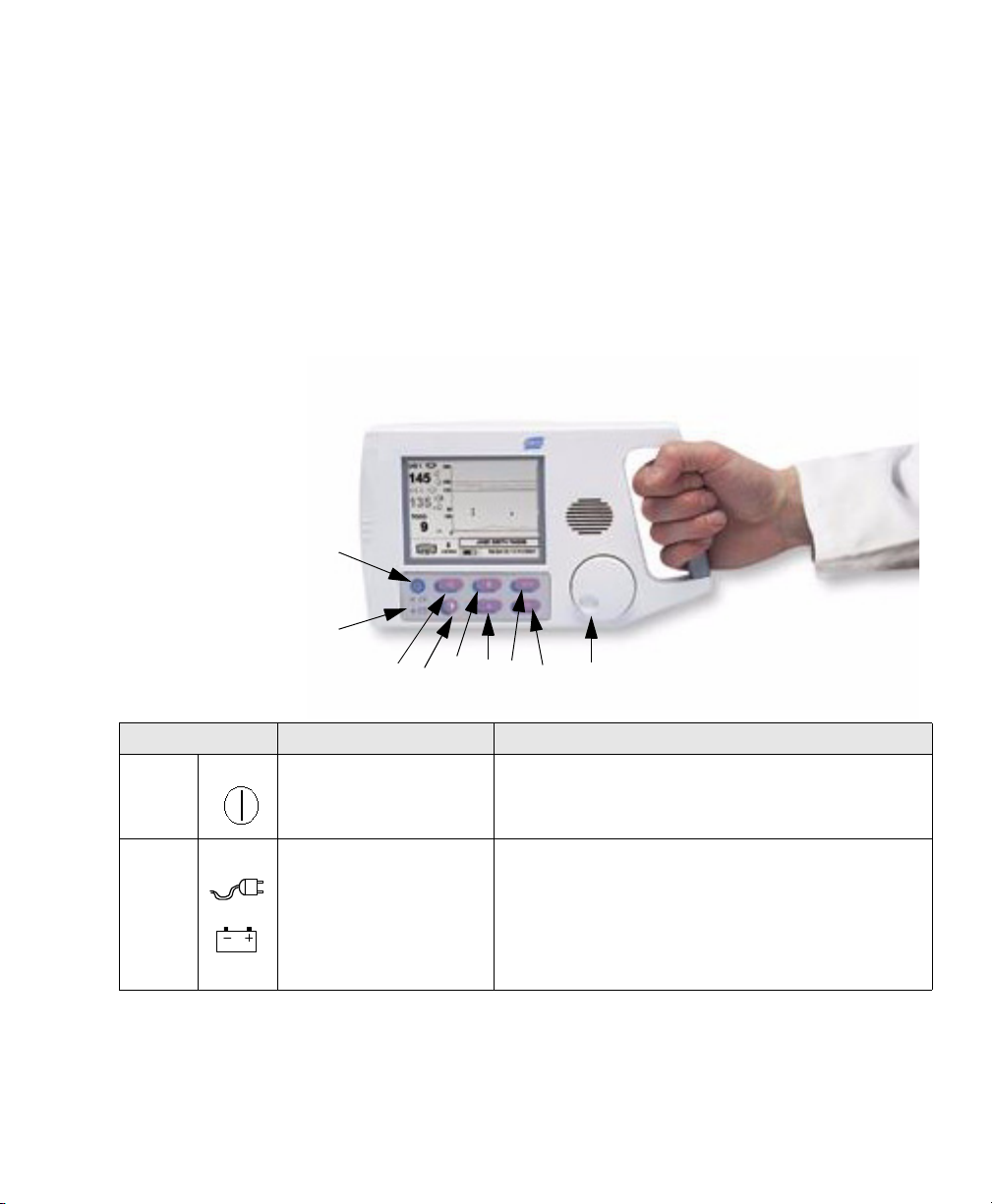
Quick Reference
This chapter is a quick reference only.You must familiarize yourself with the
safety information in Chapter 2 in order to use the monitor safely.
1
2
4
5
3
6 78
9
1
What is this? Use this... Comments
... to switch the monitor on and
1
on/off
2
power
source
Quick Reference 1
off.
...as an indicator of the power
source.
The monitor plays a jingle and displays a startup screen whilst
performing a power-on self test.
Indicates whether monito r is pow e red from AC power source via
the power supply or battery only.
Recharge the battery after use. It is recommended to keep it
charged. Unlike a nickel-cadmium battery, lead acid batteries do
not suffer from the “me mo ry” effect so there is no need to
discharge it completely before recharging.,
Page 12
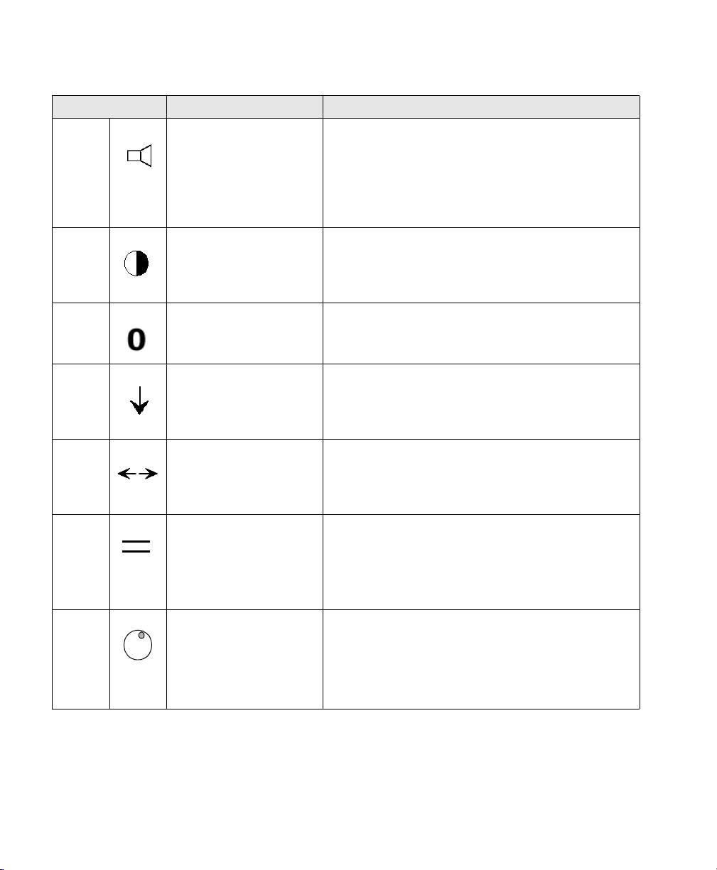
What is this? Use this... Comments
3
volume/
alarm
silence
4
contrast
adjust
5
Toco zero
6
clinician
marker
7
trend
scroll
8
grid line
enable
...to silence a n alarm or set
volume on an ultrasound
channel.
...to enter/ex it contrast adjust
mode.
...to zero the Toco data to the
baseline.
...to annotate the trace w ith the
clinician e vent marker.
...to enter/exit trend scroll
mode.
...to enter/exit grid mode . Use during an NST to more easil y de te rmine duration and
If an alarm is sounding, press this button to silence it.
If no alarm is sounding, press this once to select ultrasound channel
1, or twice for ultrasound channel 2 (if present). Then rotate the
wheel to adjus t the alarm volume of the selected ch annel. Press it
again to exit the adjustment mode. You can still change the volume
on an ultrasound channel even if an alarm condition is present.
Press once to ente r adj ust mode an d aut oma tica ll y res et th e cont r ast
to the factory default level. Rotate the wheel to alter the contrast.
Press a second time to exit the mode.
New Toco data is shifted to the prese t baseline after you press this.
Zero the baseline before you commence monitoring
Press once to make one annotat ion on patient trend data. Mult iple
presses marks the trace multip le times.
Press once to enter trend scroll mode. Rotate the knob to slide the
trend data across the screen. Press a second time to exit the mode.
frequency of FHR accelerations abo ve 15 BPM.
Press once to set lines 15 BPM apart. Rot ate na vi gation wheel to
adjust the position of the paired lines. Press a second time to return
to the previous monito r in g mode.
9
navigation
wheel
...to navigate around the screen. Turn the wheel to highlight an i tem. Pre s s the wh ee l t o sel ec t yo ur
choice. Use this to select frames, which allow you access to that
frame’s associate menu. When in a menu, turn the whee l to cycle
through items, values etc. Press the whee l to se lect the item or
value. Full instructions on how to use nav igation wheel to change
settings and alarms are gi ven on page 25.
2 Quick Reference
Page 13

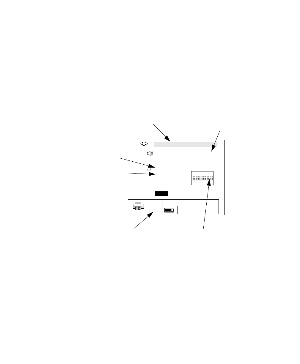
Monitoring Screen Display
1
1
24252627
10
US 1
1
50
2
3
4
5
6
7
8
9
US 2
32
TOCO
20
(5)
240
150
110
30
100
0
3
11
12
13 14 15 16 17 18
1. Ultrasound channel indicator
2. Hea r t rate icon for Fetal Heart Rate 1
3. FHR 1 on US1 (in FHR numeric frame)
4. FHR1 amplitude volume indicator (off)
5. Alarm status indicator for FHR1 (alarm on)
6. Hea rt r ate icon for FH R2
7. Fetal Heart Rate 2 on US 2
8. FHR2 amplitu de volu m e in dicator (high)
9. Trace offset se pa ration “on” indicator
10. Alarm status indicator for FHR2 (off)
11. Toco valu e (i n Toco numeric frame)
12. Present Toco baseline value
13. Communications frame (recorder attached)
14. Paper speed (3 cm/min)
cm/min
JANE DOE 194848
16:34:12 2/14/2001
15. Power status fram e (running from battery)
16. Time and....
17. .....Date (in Time/Date frame)
18. Toco baseline reference
19. Patient ID frame
20. Toco Trend frame
21. Clinician marker
22. Patient marker
23. Heartrate tre nd frame
24. Ultrasound grid lines (normocardia)
25. Ultrasound trend for FHR2 (lighter trace)
26. Ultrasound trend for FHR1 (darker trace)
27. Trend scroll indicator (active)
23
22
21
20
19
Quick Reference 3
Page 14
Ultrasound Monitoring
1
U/S 1
50
Ultrasound Menu
Trace Separation 0 bpm
FHR Upper Limit 150 bpm
FHRLower Limit 50 bpm
FHR Alarm Delay 30 sec
Loss of FHR Delay 120 sec
Alarm Status
Disable
1. Connect US transducer (red connector) to upper US red socket.
2. Go to Ultrasound menu, and check alarms. Adjust if necessary.
3. Adjust US speaker volume (press speaker key and turn wheel).
4. Fasten belt around patient.
5. Find fetal heart position.
Return
6. Apply US gel to transducer and apply transducer to patient.
7. Fasten transducer in position on belt when you get a good signal.
8. Verify this is FHR.
9. Start monitoring.
10. Periodically compare mother’s pulse with FHR signal to ensure you
monitor FHR, not maternal heart rate.
11. Switch off when finished. Always switch off between patients.
Toco Monitoring
TOCO
20
TOCO Menu
TOCO Baseline (5)
Return
(5)
1. Connect Toco transducer (brown connector) to brown Toco socket.
2. Position transducer on fundus and obtain good signal.
3. Fasten belt and clip transducer to it. Check belt tension.
4. Go to Toco menu and check baseline value. Adjust if necessary.
5. Zero baseline once, between contractions.
6. Start monitoring.
7. Switch off when finished. Always switch off between patients.
Non-Stress Test (NST) Aid
1. Press the grid line key on the front of the monitor.
2. Turn wheel to position the 15 bpm apart grid lines on FHR to help you
determine frequency and duration of accelerations.
Event Markers
1. Press the clinician mark er on the fron t of the monitor to mark the trace or
2. Patient presses button on remote marker cable to mark trace when she
perceives fetal movement.
Viewing Stored Fetal Traces on Screen
1. Press the trend scroll key on the front of the monitor.
2. Turn the navigation wheel to scroll through stored traces).
4 Quick Reference
Page 15

Printing and Transmitting
Communications Menu
Data Transfer Stopped
Destination
Paper Output
Paper Speed
Paper Style
Modem Initialization
Number to Dial
Return
cm
3
min.
Printer/Recorder
Patient Records
3 cm/min
USA
1. Turn navigation wheel to highlight Communications Frame.
2. Press the wheel to activate the frame and view menu
options.
3. Turn the wheel then press it to select each menu option in
order.
How do I... ...this is how
...print stored fetal traces to a printer or the recorder?
Connect the monitor directly to the printer using the 25-pin to 36
pin cable that belongs to the printer.
...transfer stored fetal traces to FM-2 viewer utility software?
Connect the monitor directly to the comp ut er us in g the 9 -pi n ca ble
M1380-61624 that comes wi th t he software OR
Connect the monitor to a modem using the 9-pin to 25 pin cable
that came with the modem.
...print current fetal trace realtime to O B TraceVue?
Connect the monitor directly to OB TraceVue using the 9-pin
cable M1380-61624.
...remotely transfer stored fetal traces to OB TraceVue
Connect monitor to modem using the 9-pin to 25 pin cable that
came with the modem.
...print current fetal trace realtime to the recorder?
Connect the monitor directly to the recorder using the 25-pin to
36-pin cable that belongs to the recorder.
...print a summary list of stored trace IDs to a p r inter?
Connect the monitor directly to the printer using the 25-pin to 36
pin cable that belongs to the printer.
1. Paper output -> Patient records
2. Destination -> Printer/record er
3. Data Transfer -> Start data transfer -> Yes
4. Select:
– “yes” for trace of displayed ID
– “no” to display ID of next tr ace
– “all” to print all remaining stored traces.
1. Destination -> FM-2 View e r
2. Data Transfer -> Start data transfer -> Yes
3. Select:
– “yes” for trace of displayed ID
– “no” to display ID of next tr ace
– “all” to print all remaining stored traces.
1. Destination -> System Online
2. Data Transfer -> Start data transfer -> Yes
1. Destination -> System Batch
2. Data Transfer -> Start data transfer -> Yes
3. Select:
– “yes” for current record
– “no” to dis play ID of next re cord
– “all” to print all stored traces.
1. Paper output -> Current record
2. Destination -> Printer/record er
3. Data Transfer -> Start data transfer -> Yes
1. Paper output -> Summary list
2. Destination -> Printer/record er
3. Data Transfer -> Start data transfer -> Yes
Quick Reference 5
Page 16

6 Quick Reference
Page 17

Safety
Instructions for Safe Operation and Use of the FM-2 Monitor
Visually inspect the monitor and accessories periodically to ensure that the
monitor, cables, line cords, transducers and instruments have no visible evidence
of damage that may affect patient safety or monitoring performance. Do not use
if there is any visible sign of damage.
Only the power supply supplied with the monitor is approved for use in
supplying external power for operating and recharging the monitor’s internal
battery.
Only the supplied AC line cord, or its equivalent, is approved for use with the
recorder.
Do not attempt to service the monitor or recorder. Only qualified service
personnel should perform any needed internal servicing.
2
The monitor is not specified or intended for operation during the use of
defibrillators or during defibrillator discharge.
The monitor is not specified or intended for use in the presence of
electrosurgical equipment.
The monitor is not specified or intended for use i n conjunction with any o ther
type of monitoring equipment except the specific devices identified for use in
this book.
Perform safety testing in accordance with local legal requirements to ensure
proper patient safety.
Do not use the monitor if it fails its power-on self-test procedure.
Safety 7
Page 18

Warnings
Warnings
WarningWarning
EXPLOSION HAZARD: Do not use the monitor in a flammable
atmosphere where concentrations of flammable anesthetics or other
materials may occur.
WarningWarning
SHOCK HAZARD: The power receptacle must be a three-wire grounded
outlet. Never adapt the three-prong plug from the power supply or
accessory to fit a two-slot outlet. If the outlet has only two slots, make sure
that it is replaced with a three-slot grounded outlet before attempting to
operate the monitor.
WarningWarning
Do not connect to an electrical outlet controlled by a wall switch.
WarningWarning
SHOCK HAZARD: Do no attempt to connect or disconnect a power cord
with wet hands. Make certain that your hands are clean and dry before
touching a power cord.
WarningWarning
Use only patient cables and transducers supplied with the monitor. Use of
any other patient cables may result in out-of-specification performance and
possible safety haz ards.
WarningWarning
Take care to position the monitor securely when overhead. Avoid insecure
positioning.
WarningWarning
If the monitor has been exposed to temperature ranges outside the specified
operating range, allow it to return to the correct operating range before
turning it on.
8 Safety
Page 19

Warnings
WarningWarning
Service may be performed by qualified service personnel only. The monitor
has no user serviceable parts.
WarningWarning
Disconnect the printer or recorder from the AC power before connecting
them to the monitor.
Safety
9
Page 20

Cautions
Cautions
Caution
US law restricts this device to sale by, or on the order of, a physician.
Caution
Keep the operating environment free of d ust, vibrations, corrosive, or flamma ble
materials, and extremes of temperature and humidity. Keep the unit clean and
free of transducer gel and other substances.
Caution
When installing the unit into a cabinet, allow for adequate ventilation,
accessibility for servicing, and room for adequate visualization and operation.
Caution
Do not operate the unit if it is damp or wet because of condensation or spills.
A voi d using the eq uipmen t immediat ely after mov ing it from a cold environment
into a warm, humid location.
Caution
Never use sharp or pointed objects to operate the front-panel switches.
Caution
General purpose personal computers, printers and modems are not designed to
meet the electrical safety requirements of medical devices. Connect them with a
cable of sufficient length to locate them outside of the patient vicinity. This
means a minimum distance of 1.5 meters from the patient’s bed or chair. Do not
connect the FM-2 recorder to the monitor at the same time as a non-medical
device (com puter, printer or modem) if the recorder is located in the patient
vicinity. For additional information refer to IEC/EN Standard 60601-1-1.
10 Safety
Page 21

Cautions
Caution
Do not autoclave or gas sterilize the monitor or any accessories. Follow cleaning
and disinfection instructions. When washing the transducer belts, the water
temperature must not exceed 60
o
C (140oF).
Caution
Do not use the transducer’s ring clip to secure the belt around the patient - you
must use a fixing button on the belt for this. Using the transducer clip to secure
the belt may damage the transducer and does not keep the belt in place reliably.
Caution
Do not mistake demonstration data for genuine patient data.
Safety
11
Page 22

Cautions
12 Safety
Page 23

FM-2 Fetal Monitor Intended Use
3
Getting Started
FM-2 is a Fetal Monitor for non-invasively measuring, and showing maternal
uterine contractions and the fetal heart rate as a graphical display and optionally
on a strip chart recorder, printer or OB TraceVue system. The data is intended to
aid in assessing the well being of the fetus during the final trimester of
pregnancy (Non-Stress Test). This device is for use only by trained medical
personnel located in hospitals, clinics, doctors' offices and in the patient's home
or during transport, under the direction of a licensed practitioner.
Getting Started 13
Page 24

Check List
Check List
Familiarize yourself with the monitor and its components by reading this book.
Use this check list to install, set up and configure your monitor.
Tasks
Task 1: Check shipment 15 !
Task 2: Attach power cables and switch on 16 !
Task 3: Set the language 18 !
Task 4: Set the time and date 19 !
Task 5: Set the paper style and speed 20 !
Task 6: Start monitoring 37 and 47
See
Page
Done
14 Getting Started
Page 25

Checking the Shipment
Use this table to check your delivery. Retain the original packaging material in
case you need to return the monitor.
Checking the Shipment
Monitor (M2922A) Shipped
1 x Ultrasound Transducer (or two, if additi ona l transducer ordered for twins)
2.5m cable
Ultrasound transmission Gel 1 bottle
Reusable Transducer Belts (M1562A)
1.3m long, 5cm wide, with button holes and pre-attached buttons. Can be further
cut. Contains latex.
Toco Transducer
2.5m cable
Remote Event Marker 1
Transducer knob adapters 1 pack
Pocket Guide to Fetal Monitoring and Assessm ent by Susa n Martin Tucker, 4th
edition, English language orders only ISBN: 0-323-00884-4
Instructions for Use and Service Guide 1
Power Supply and Power Cord (110 or 220V) 2 meter 1
Recorder (M2925A)
(110V or 220V as appropriate)
Power Cord 2 meter 1
1
2 belts
1
1
Shipped
PC parallel printer cable for connecting monitor to recorder. 1
Recorder Paper approp riate for country 1 pack
Getting Started
15
Page 26

Setting Up Your Monitor the First Time
1
A
Setting Up Your Monitor the First Time
Connecting the Power Supply
One cable is permanently attached to the power supply. Connect this cable to the
rear of the monitor, at the input marked . Insert the AC line cord into
the three-pronged IEC receptacle on the power supply. Insert the other end into
an appropriate wall outlet.
WarningWarning
Do not connect to an electrical outlet controlled by a wall switch
WarningWarning
SHOCK HAZARD: Do not attempt to connect or disconnect a power cord
with wet hands. Make certain that your hands are clean and dry before
touching a power cord.
5V ∼ 1
WarningWarning
SHOCK HAZARD: The power receptacle must be a three-wire grounded
outlet. Never adapt the three-prong plug from the power supply or
accessory to fit a two-slot outlet. If the outlet has only two slots, make sure
that it is replaced with a three-slot grounded outlet before attempting to
operate the monitor.
16 Getting Started
Page 27

Using the Battery
To run from the monitor’s internal battery, switch the monitor on, without the
power supply connected. Recharge the battery using the power supply, either
during monitoring or when the monitor is switched off.
Connecting the Remote Marker Cable
Insert the cable into the connector, marked , at the side of the monitor.
Mounting on Wall or Rollstand
Instructions for mounting your monitor come with the GCX mounting kit.
Setting Up Your Monitor the First Time
Getting Started
17
Page 28

Setting Up Your Monitor the First Time
Choosing Your Language
The monitor is delivered with English as the default language. To choose a
different language:
1. Switch on the monitor.
2. Rotate the navigation wheel
3. Push the wheel to display the Service Menu. The first item (“Set
4. Select “Set Language” to see a second menu with all language choices.
5. Rotate the wheel to highlight your language.
6. Press the wheel to select it.
Service Menu
“Set Language” menu
item
Power status frame
7. Turn the monitor off and switch on again to activate the new language.
1
until the Power status frame is highlighted.
Language”) shows the current operating language.
US 1
US 2
TOCO
(5)
cm/min
240
150
110
100
3
Service Menu
Set Language
System On-Time
Demo Mode
30
0
View Error Log
View A/D Values
English
Deutsch
Svenska
Italiano
Norsk
Dansk
Espanol
Francais
Nederlands
Suomi
JANE DOE 194848
16:34:12 2/14/2001
current
operating
language
Caution
Selecting an unfamiliar language may make it difficult to resume normal
operation.
1. See page 25 for full instructions about using the navigation wheel.
18 Getting Started
Page 29
Setting the Time and Date
1
Use the Time and Date menu to set the current time and date, and their display
formats. Remember to change the time when daylight saving time changes
(unless realtime monitoring with an OB TraceVue system, when the system
communicates the time and date change to the monitor).
1. Select the Time and Date frame.
2. Rotate and press the wheel to select the setting you want to change.
3. Rotate the wheel to change the values. Press the wheel to save the change.
4. Repeat until you have set the time, time format, date, and date format.
Time and Date Menu current settings
Setting Up Your Monitor the First Time
Changing the
Time or Date
During Moni-
toring
US
50
TOCO
20
time and date frame
(5)
3
cm/min
Time/Date Menu
Set Time
Set Date
Set Time Format
Set Date Format
Return
12 Hour
MM/DD/YYY
DD.MM.YYYY
YYYY/MM/DD
JANE DOE 194848
16:34:12 2/14/2001
selecting a different date
format
Always start a new monitoring sessio n after changing the time or date. Although
the new time is shown on the monitoring screen, it is not stored within the fetal
trace record.
Getting Started
19
Page 30
Setting Up Your Monitor the First Time
1
Setting the Paper Style and Speed
1. Select the Communications frame.
2. Select Paper Style.
3. Rotate the wheel to change the values (USA or International). Press the
wheel to save the change.
• USA: Orange paper 30-240 FHR scale
• International: Green paper, 50-210 FHR scale
4. Using the same technique, now set the paper speed (1, 2 or 3 cm/min).
communications menu
paper speed
paper style
communications frame
US
TOCO
20
50
Data Transfer
Destination
Paper Output
Paper Speed
Paper Style
Modem Initialization
Number to Dial
Return
(5)
cm
3
min.
Communications Menu
Stopped
Printer/Recorder
Patient Records
3 cm/min
USA
International
JANE DOE 194848
16:34:12 2/14/2001
current settings
changing the paper
style
20 Getting Started
Page 31

This chapter gives an overview of how to use your monitor, and its features. It
shows an example fetal trace and gives some general practical information.
More About the Monitor
It can monitor fetal heart rate (FHR) and external uterine pressure (Toco),
showing the patient data on its integral display, and saving up to 12 hours of
patient data in its memory. It can output this data, realtime, on a strip chart
recorder or OB TraceVue system. The data includes graphic trend data and text
information about hardware and software configuration, date and time and so
forth.
Additionally, you can download this stored data to a printer via a direct cable
link, or to a remote obstetrical surveillance system such as OB TraceVue or to a
PC running the FM-2 viewer utility software.
4
General Information
Monitoring Screen Frames
The monitoring screen is divided into frames.
Fetal Heart Rate Numeric (US1) Frame
This displays FHR, heart rate icon, alarm status icon, and speaker volume icon.
The heart rate value shows the most recent calculated fetal heart rate. The heart
rate icon blinks at the measured heart rate interval when a valid rate is present.
The volume icon gives an indication of the speaker volume setting for the FHR
General Information 21
Page 32

Monitoring Screen Frames
sounds. This icon changes when you adjust the speaker volume setting. The
alarm icon is a bell. A diagonal line through the bell indicates alarms are
disabled. A bell without a diagonal line indicates alarms are enabled.
When you connect a second ultrasound transducer, the heart rate frame includes
the second fetal heart rate, heart rate icon, alarms status icon and speaker
volume.
The trace offset icon appears in the heart rate frame if you have connected two
ultrasound transducers and enabled the ultrasound trace offset.
Heart Rate Trend Frame
The heart rate trend frame displays a graphical representation of the fetal heart
rate. The vertical scale corresponds to the selection of the recorder paper (30 to
240 BPM for US style paper, 50 to 210 for International style paper). The graph
displays six minutes of data if the monitor is set for a print speed of three cm per
minute, nine minutes of data when set for two cm per minute and 24 minutes
when set to one cm per minute.
This frame shows two heart rate trends when you use two ultrasound
transducers.
The normocardia lines make it easier for you to observe heart rate trend or heart
rates that exceed limits. These are positioned at 110 and 150 BPM.
This graphic frame also displays heart rate data when you scroll through
historical patient data in trend scroll mode.
Toco Numeric Frame
This frame contains the numeric value from the Toco transducer, representing
uterine activity. It also shows the present Toco baseline value. You can adjust
the Toco baseline.
Toco Trend Frame
The Toco trend frame displays uterine activity trend data. The scale is from zero
to 100 in relative units. The graph displays six minutes of data if the monitor is
set for a print speed of three cm per minute, nine minutes of data when set for
22 General Information
Page 33

two cm per minutes, and 24 minutes when set to one cm per minute. This
graphical frame also displays uterine activity data when you scroll through
patient d a t a .
Power Status Frame
This frame displays an icon to indicate the monitor’s method of power. There is
no indication of batte ry charge st atus when you are working from AC power.
Symbol Definition Symbol Definition
Monitoring Screen Frames
Monitor is powered by
battery. Number of filled
segments indicates battery
charge status (battery fuel
gauge). A fully charged
battery shows all segments
filled.
Communications Frame
This frame shows the status of devices connected to the monitor’s serial
interface port. See Chapter 8, “Printing and Transmitting Records” for more
details.
Time and Date Frame
This frame shows the current time and date for the monitor. You can change
these when necessary; see “Setting the Time and Date” on page19.
Patient ID Frame
This displays the patient identification, generated automatically by the monitor
each time you switch on. It uses a time and date encoded identification scheme
to ensure no duplication of identification. You can change this, entering an ID
(such as name) if you want; see “Configuring Patient ID” on page 30.
Monitor is operating from
AC power.
General Information
23
Page 34

Monitoring Screen Frames
1
A
Monitor Symbols
These symbols appear on the monitor and its associated equipment
Symbol Definition Symbol Definition
5V ∼ 1
RS-232
Remote marker input
connector
Drip-proof equipment
classification
Class II equipment symbol
(double insulation)
Type BF applied part
symbol
Power supply connector Refer to accompanying
documents
RS-232 connector (symbol
on monitor housing)
RS-232 connector (symbol
on monitor label)
Functional earth Printer connection
24 General Information
Page 35

Changing Monitor Settings
1
1
Using the Navigation Wheel
You navigate through, and make changes to, screen elements by rotating and
pressing the navigation wheel. Rotate the wheel to highlight frames on the
screen. When a frame is selectable it has a heavy box drawn around it. Press the
wheel to select the frame.
The monitor’s response may be effective immediately, or it may display a Level
2 menu that “pops up” on screen without removing the Level 1 menu.
Example of a Change Operation
To change the fetal heart rate alarm status:
1. Rotate the wheel to highlight the Ultrasound frame. A heavy border
appears around that frame.
Changing Monitor Settings
US 1
50
select the
Ultrasound
frame
US 2
32
TOCO
20
General Information
(5)
cm/min
240
150
110
100
30
0
3
JANE DOE 194848
16:34:12 2/14/2001
25
Page 36

Changing Monitor Settings
1
1
2. Press the wheel. The Ultrasound Menu appears. This is a Level 1 menu.
US
Trace Separation 0 bpm
FHR Upper Limit 150 bpm
FHRLower Limit 50 bpm
FHR Alarm Delay 30 sec
Loss of FHR Delay 120 sec
Alarm Status
Ultrasound Menu
(level 1 menu)
50
TOCO
20
Return
(5)
3
cm/min
3. Rotate the wheel to highlight Alarm Status.
US
Trace Separation 0 bpm
50
“Alarm Status”
highlighted
TOCO
FHR Upper Limit 150 bpm
FHRLower Limit 50 bpm
FHR Alarm Delay 30 sec
Loss of FHR Delay 120 sec
Alarm Status
20
Return
(5)
3
cm/min
Ultrasound Menu
Disable
Jane Doe 194848
16:34:12 2/14/2001
Ultrasound Menu
Disable
Jane Doe 194848
16:34:12 2/14/2001
26 General Information
Page 37

Changing Monitor Settings
1
1
4. Press the wheel. A Level 2 menu appears and the current value is
highlighted. This illustration shows Disable.
Alarm status
level 2 menu
“disable”
US
50
TOCO
Ultrasound Menu
Trace Separation 0 bpm
FHR Upper Limit 150 bpm
FHRLower Limit 50 bpm
FHR Alarm Delay 30 sec
Loss of FHR Delay 120 sec
Alarm Status
20
Return
(5)
3
cm/min
Jane Doe 194848
16:34:12 2/14/2001
5. Rotate the wheel to highlight the value “Enable”.
US
50
Alarm status
level 2 menu
“enable”
TOCO
Ultrasound Menu
Trace Separation 0 bpm
FHR Upper Limit 150 bpm
FHRLower Limit 50 bpm
FHR Alarm Delay 30 sec
Loss of FHR Delay 120 sec
Alarm Status
20
Return
(5)
Disable
Enable
Disable
Enable
Jane Doe 194848
16:34:12 2/14/2001
“Return”
3
cm/min
6. Press the wheel to activate the change.
7. Rotate the wheel to highlight “Return”.
8. Press the wheel to return to the normal monitoring screen.
Changes take effect when you exit from the menu. While a menu is displayed, if
no wheel or button activity occurs for 20 second s, the men u closes and return s to
the monitoring screen.
General Information
27
Page 38

Preparing for a Monitoring Session
When this Guide tells you to “Select” an item, it means you must rotate the
wheel until the item you want is highlighted. “Confirm” means press the wheel
to activate your selection.
Preparing for a Monitoring Session
Before you start monitoring, visually inspect the monitor, transducers and
accessories to make sure that all are in good condition. If any part is broken or
damaged you should not use it.
Fastening a Belt
Arrange the belt around the patient until it is tight but still comfo rt a ble. Fas ten it
by pushing the fixing button through the over la ppi ng s ectio n of t he b e lt, w ith the
point facing away from the patient. Ensure that the fixing button and the loose
ends of the belt are at the patient’s side.
Do not overtighten the belt; excessive compression of the maternal abdomen is
uncomfortable for the patient and may result in incorrect measurements.
28 General Information
Page 39

Clipping a Transducer to the Belt
Secure the belt as described above. When you have positioned a transducer
satisfactorily clip it to the belt, taking care not to catch the belt material in the
edge of the ring clip. You can then slide the transducer along the belt to
reposition it if necessary.
Every patient is different, and correct transducer placement is important to
ensure proper monitoring.
Preparing for a Monitoring Session
Alternatively, you can fix a button to the transducer and use this to attach the
transducer to the belt. See the Installation Note that comes with the Transducer
Knob Adapter for assembly instructions.
Caution
Do not use the transducer’s ring clip to secure the belt around the patient - you
must use a fixing button on the belt for this. Using the transducer clip to secure
the belt may damage the transducer and does not keep the belt in place reliably.
Connecting a Transducer to the Monitor
Connect the color coded transducers (brown for Toco, red for Ultrasound) to the
matching color socket at the side of the monitor.
General Information
29
Page 40

Preparing for a Monitoring Session
Eliminating Electromagnetic Interference
An electromagnetic field can interfere with the ultrasound transducer and cause
a false heart rate reading that does not originate from the patient. Although this
is rare, it might happen in the vicinity of large machinery. To avoid the
possibility of these signals being misinterpret ed as fetal heart rates, you should
follow this procedure before you start monitoring whenever the monitor is used
in a new location or if you know that electrical machinery is being operated in
the vicinity.
Connect the ultrasound transducer to the monitor, do not yet posi tion on patient,
and observe the heart rate indications on the screen for 30 seconds. An
intermittent display of random heart rates (this is called artefact) is acceptable.
However, if there is a constant display of a heart rate lasting more than five
seconds, this is an indication that there is a source of electromagnetic
interference in the vicinity.
You can use the monitor in this environment if the artefact heart rate indication
ceases when you:
• Move all line cords and line-powered equipment at least six feet away
from the monitor. Remember to check for extension cords running behind
or under the bed and for equipment in adjacent rooms.
• Remove the power cord from the monitor’s power supply and operate
from battery.
• Unplug the monitor’s recorder and move it out of the vicinity.
If these measures do not result in the cessation of the heart rate artefact, you
cannot use the monitor safely in this environment.
Configuring Patient ID
When you switch the monitor on, it creates a Patient ID based on the current
date and time. For example, if you turn the monitor on at 4:37:54pm on May 11
2001, the Patient ID will be 051101163754.
(month.day.year.hour.minute.second).
1. The monitor always uses this form at for the ID, ev en if you h ave chosen 12
hour time format, or DD.MM.YYYY date format.
30 General Information
1
Page 41

Preparing for a Monitoring Session
1
If you want to give a more meaningful identification, you can change the ID to,
for example, the patient’s name, or perhaps medical record number. A
subsequen t change (or correction) of this patient ID automatically closes th e
current record and starts a new record with a new ID.
Use the Patient ID Menu to change the default patient identification.
1. Select the Patient ID frame.
Patient ID Menu
US
Patient ID Menu
Patient ID 0214961630
50
TOCO
20
current patient ID
2. Select the patient whose ID you want to enter.The monitor displays the
Set Patient ID menu.
3. Rotate the wheel to highlight a character in the Patient ID.
4. Press the wheel to activate the character.
5. Rotate the wheel until the monitor displays the character you want.
Available characters are 0-9, A-Z (uppercase only) and “space”, with 24
character maximum.
6. Press the wheel to save the change. Repeat until you have completed the
Patient ID.
7. Select:
– OK to store this new Patient ID.
– Clear reset the Patient ID to blanks.
(5)
3
cm/min
Return
0214961630
16:34:12 2/14/2001
patient ID frame
General Information
31
Page 42

Preparing for a Monitoring Session
1
Cancel to abandon your changes and leave the original patient ID unchanged.
patient ID sub-menu
Adjusting Alarm Limits
Always check that the current alarm limits are appropriate for your patient. If
they are not, adjust them. Instructions for checking and adjusting alarms are
given in the chapter for the parameter you are measuring. When you switch off
the monitor, the most recently set alarm limits are retained. They are not reset to
factory defaults when you next switch on.
US
50
TOCO
20
(5)
3
cm/min
press Cancel to
abandon changes
Patient ID Menu
Patient ID (0214961630)
Set Patient ID
0214961630
OK
Return
0214961630
ClearCancel
16:34:12 2/14/96
press “Clear” to reset
patient ID
Marking an Event
Use the remote marker to record significant events (for example, when pain
medication is administered or when the mother changes position). This marker
time is recorded on the fetal trace. There are two markers:
32 General Information
Page 43

Clinician marker: clinician presses the marker key on the monitor. The
trace is marked with a downwards facing arrow, in the uterine activity area
of the trace.
Patient marker: patient presses the button on the remote event marker
cable. The trace is marked with an upwards facing arrow in the heart rate
area of the trace.
Multiple rapid presses result in partial printing of all mar ker arrows and full
printing of the last one.
Finishing a Monitoring Session
Always switch off the monitor between patients to ensure that a new fetal trace
and ID are generated when you switch on ag ain for the nex t patien t. If you allo w
the monitor to run without switching off between patients, it will store this
“empty trace” in its memory. This is confusing when you use the scroll feature,
and wasteful of paper when you print the fetal trace.
Configuration Settings
Configuration Settings
The monitor ships with some factory-set defaults for user-con figurable items
(such as alarm limits, alarm delays and so forth). In most cases, the monitor
retains the most recent change to these values after it is switched off and then on
again.
There are two exceptions. US trace separation value always returns to 0 and the
monitor always generates a new patient ID when the power is cycled (that is,
when the monitor is switched off and then on again).
General Information
33
Page 44

Using the Battery
Using the Battery
You can run the monitor for approximately six hours on battery power at room
temperature of 25
monitoring at 10
operating temperature and number of recharge cycles affects this. A battery life
cycle is approximately 200 charge/discharge cycles.
Low Power Warning
A low power warning occu rs when the battery power i s ru nning low. The battery
fuel gauge flashes, and a repetitive audible tone sounds. Remaining monitoring
time is typically 30 minutes with a new battery at room temperature of 25
an older monitor, in which the battery has had a number of recharge cycles, it
may occur when fewer minutes remain.
The warning continues until the low power condition disappears (when you
connect the monitor to an AC power supply) or until the system stops
functioning because of the low power.You cannot silence it, and you cannot
adjust its volume.
The monitor retains any stored fetal traces, even if it shuts down because of lack
of battery power.
Recharging the Battery
o
C from a fully charged battery (with a minimum of two hour s
o
C from a fully charged battery). The age of the battery,
o
C. In
Use the power supply to recharge the battery from an AC power source. This
takes a maximum of 14 hours when monitoring simultaneously, or 8 hours if no
monitoring occurs. Typical times are 11 hours if you are monitoring
simultaneously, or 4.75 hours if no monitoring occurs.
Replacing the Battery
Life expectancy of a battery depends on the frequency and duration of use. We
recommend replacing the battery every 2 years.
34 General Information
Page 45

Only a trained service professional should change the battery; instructions are
given in the Service Guide.
Replace the battery if it is known to be fully charged and the following
conditions occur:
• battery discharges quickly when you are using it
• the remaining time in the battery after the battery alarm first occurs is less
than 10 minutes.
• the battery does not recharge to full capacity (indicated by the battery fuel
gauge on the monitor).
Storing
A stored battery loses capacity over time. To minimize loss of capacity, recharge
the battery at least every six months. A battery typically has three to five years
shelf life.
Getting the Best out of Your Battery
Unlike a nickel-cadmium battery, a lead acid battery does not have a “memory”,
and so there is no need to discharge it before recharging it. Here are some tips to
help you get the best out of your battery:
Demonstration Mode
• Run the monitor from its power supply where possible.
• Recharge a stored monitor periodically.
• For convenience, recharge the battery fully after use.
Demonstration Mode
The monitor has a demonstration mode in which the monitor can perform all
normal monitoring display, communications and printing activity using the
internally generated data (except ultrasound audio output). You can change
alarm limits, status and so forth. You enable and disable Demo mode using the
Power status frame’s Service Menu. Switching the monitor off and then on again
also disables Dem o mode.
General Information
35
Page 46

Demonstration Mode
Points to note about Demo mode:
• The monitor displays the word >>Demo!<< in the Patient ID so that you
can see that you are not viewing or monitoring real patient data.
• Connecting a transducer does not disable the Demo mode.
• Disabling Demo mode via the Service Menu, or switching the monitor off
and then on again, automatically starts a normal record.
• The demo trace is stored in the memory each time you enter Demo mode.
The Demo trace always has the ID >>Demo<< and contains the same
trace data.
Caution
Do not mistake demonstration data for genuine patient data.
36 General Information
Page 47

Monitoring Fetal Heart Rate
Monitoring fetal heart rate using ultrasound is recommended from the 25th week
of gestation for non-stress or normal routine fetal monitoring. Performing
imaging at the same time as ultrasound fetal monitoring may cause false FHR
readings, and the trace recording may deteriorate.
FHR Monitoring
What You Need
5
• Ultrasound transducer
• Ultrasound gel
• Transducer belt and button
Preparing the Monitor
1. Switch the monitor on and make sure the normal monitoring screen
appears on the display.
2. Check the monitor’s power source. If you are using battery power, check
the power status frame to ensure that the battery has sufficient charge to
complete the monitoring session. Use the power supply if the charge is too
low.
3. Check for electromagnetic interference (see page 30).
4. Plug the Ultrasound transducer into the monitor’s US1 socket.
5. Check, and if necessary change, the alarm settings (see page 43).
1. Never start a new monitoring se ssion if the monito r has been left o n from
a previous session. Cycle the power (switch off then on again) be fore starting
to monitor. This ensures that the monitor generates a new fetal trace record,
with unique ID.
Monitoring Fetal Heart Rate 37
1
Page 48

FHR Monitoring
6. Adjust US1 speaker volume to mid level. If you are monitoring twins,
adjust US2 to off.
Finding the Fetal Heart Rate
1. Fasten the belt around the patient.
2. Find the fetal heart position by palpation, auscultation or ultrasound
imaging.
3. Apply a small amount of ultrasound gel in a thin layer to the transducer.
4. Apply the transducer to the patient, working it in a circular motion to
ensure the gel layer makes good contact.
5. When you have a good signal clip the transducer in position on the belt. It
can take approximately 10 seconds to get a valid HR signal.
6. Verify that the monitor is displaying a numeric fetal heart rate value.
The heart rate icon flashes at the measured heart rate interval when a valid
rate is present.
WarningWarning
Periodically compare the mother’s pulse with the FHR signal coming from
the monitor to ensure that you are monitoring fetal heart rate and are not
accidentally recording maternal heart rate. Do not mistake a doubled
maternal heart rate for FHR. For the same reason, be very careful when
interpreting a trace if you suspect fetal demise. The maternal heartrate may
be atypically high and therefore confused with that of a live fetus.
38 Monitoring Fetal Heart Rate
Page 49

WarningWarning
Never immerse the ultrasound transducer in liquid when it is connected to
the monitor unless the monitor is running on battery power only, and is not
directly connected to the AC power supply, and/or an other device (such as
a printer).
Interpreting the Data
However, interpretation of the trace is left to the clinician’s judgement.
Remember that cardiac arrhythmias or other abnormalities can cause erratic
trace data.
Disconnect unused ultrasound transducers. Continuous mechanical influence of
the unused transducer could result in an artificial trace.
Monitoring Twins
Monitoring Twins
If you have two ultrasound transducers, you can monitor a second fetus on the
second ultrasound channel. You require a second belt.
Finding the Second FHR
Connect the second transducer to the second ultrasound socket (US2). Follow
the previous steps to acquire the heart rate for the first fetus. Decrease the
speaker volume for US1, and increase the volume on US2 so that you will be
able to hear the second heart. Locate the second fetus, and verify that the
monitor displays the numeric fetal heart rate values for both fetuses. The second
heart rate icon flashes at the measured heart rate interval when a valid rate is
present.
Monitoring Fetal Heart Rate
39
Page 50

Monitoring Twins
1
Separating Two FHR Traces
To help you distinguish between fetal traces, you can offset the second fetal
heart rate by 20 BPM. The second heart rate appears on the trace 20 BPM lower
than it really is. The heart rate value shown in the numeric frame is not affected.
Use the Ultrasound menu to activate trace separation:
1. Select the FHR numeric frame to display the Ultrasound menu
Ultrasound Menu
US
50
Trace separation
TOCO
Ultrasound Menu
Trace Separation 0 bpm
FHR Upper Limit 150 bpm
FHRLower Limit 50 bpm
FHR Alarm Delay 30 sec
Loss of FHR Delay 120 sec
Alarm Status
Disable
20
Return
(5)
3
cm/min
2. Select Trace Separation.
When trace separation is active, flashes next to the US2 numeric
value.
3. Rotate the wheel to display either 0 (no trace separation) or 20 (traces
separated by 20 BPM). Confirm your choice.
Jane Doe 194848
16:34:12 2/14/2001
40 Monitoring Fetal Heart Rate
Page 51

Adjusting Ultrasound Volume
Press the speaker button and rotate the navigation wheel to increase or
decrease the amplitude of the ultrasound heart volume. The volume icon
gives you an indication of the speaker volume.
US1 You do not need to connect a transducer to the US1 channel to change the
volume of US1.
1. Press the speaker button once to select the volume for US1.
2. Rotate the wheel to adjust volume.
3. Press the speaker button to save the setting.
US2 Connect a transducer to US2 channel. It is not necessary to connect a transducer
to US1 first.
Adjusting U ltrasound Volume
1. Press the speaker button twice to select the volume for US2.
2. Rotate the wheel to adjust volume.
3. Press the speaker button to save the setting.
Monitoring Fetal Heart Rate
41
Page 52

Understanding FHR Alarms
---
Understanding FHR Alarms
The monitor can alert you if the fetal heart rate goes above or below the alarm
threshold for a time that exceeds the alarm delay setting, or if it loses the heart
rate signal entirely. You can configure these limits and times. You must ensure
the alarm status is set to enable (via the ultrasound menu, see page 44) if you
want the monitor to warn you if an alarm condition occurs.
Alarm type what you see and hear
Alarm limit
exceeded
Signal loss alarm F et al heart rate frame flashes
Fetal heart rate numeric val ue
flashes.
Monitor sounds a warning
tone.
.
Monitor sounds a warning
tone.
Silencing
the alarm
Press
...what happens
The monitor is silenced.
The alarm icon is crossed through, and
the FHR value con tinues t o flas h whil e
alarm condition persists.
When alarm condition ends, visual and
audible alerts are reactivated . The
alarm icon is no longer crossed
through.
The monitor is silenced.
The alarm icon is crossed through and
the FHR value continues to display
dashes while alarm condition persists.
When alarm condition ends, visual and
audible alerts are reactivated . The
alarm bell icon is no longer crossed
through.
42 Monitoring Fetal Heart Rate
Page 53

Configuring FHR Alarms
1
1. Select the Ultrasound Menu
Understanding FHR Alarms
Ultrasound Menu
alarm parameters
US
50
TOCO
Ultrasound Menu
Trace Separation 0 bpm
FHR Upper Limit 150 bpm
FHRLower Limit 50 bpm
FHR Alarm Delay 30 sec
Loss of FHR Delay 120 sec
Alarm Status
Disable
20
Return
(5)
3
cm/min
alarm status parameter
2. Rotate the wheel to highlight the alarm limit you want to change.
3. Press the wheel to select it. The monitor highlights the current val ue.
4. Rotate the wheel until the desired new limit is shown.
5. Press the wheel to confirm this choice.
6. Select “Return” to go back to the main monitoring screen when you have
configured the alarm parameters appropriately for your patient.
Jane Doe 194848
16:34:12 2/14/2001
enabled or disabled
These settings remain active even after the monitor is switched off and then on
again. Always check that the settings are appropriate for each patient before you
start monitoring her.
Monitoring Fetal Heart Rate
43
Page 54

Understanding FHR Alarms
Alarm Settings
Alarm Comments
FHR upper limit Fetal heart rate value at or above which the alarm so und s.
Range: 110-220 BPM (increments of 5)
Factory default: 150 BPM
FHR lower limit Fetal heart rate value at or below which the alarm sounds .
Range: 50-120 BPM (increments of 5)
Factory default: 110 BPM
FHR alarm delay Time during which the fetal heart rate is at, or exceeds, alarm limit
before alarm sounds.
Range: 10-120 seconds (10 second increments)
Factory default: 60 seconds
Loss of FHR delay Time delay between monitor losing a valid fetal heart rate and then
sounding the alarm.
Range: 10-120 seconds (10 second increments)
Factory default: 120 seconds
Alarm status Enable: All alarms are on.
Disable: All alarms are off (default)
Alarm Defaults The monitor saves alarms settings until they are next changed. When you switch
the monitor on it uses the most recently set alarm settings. It does not revert to a
factory-set default.
Monitoring
Twins
44 Monitoring Fetal Heart Rate
When you are monitoring twins, the alarm settings apply to both FHR1 and
FHR2.
Page 55

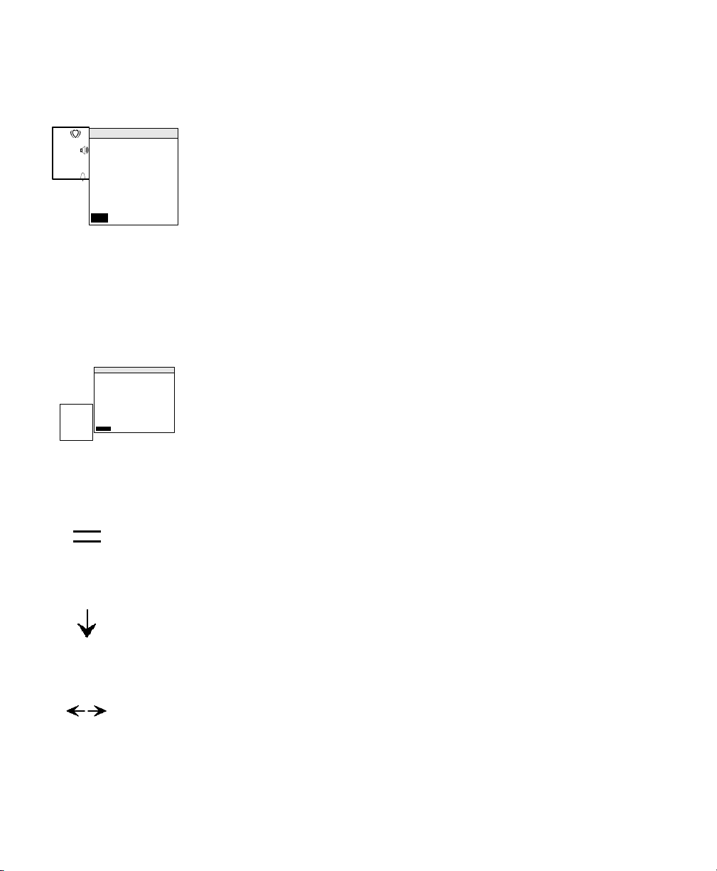
Determining FHR Acceleration Using Grid Lines
Determining FHR Acceleration Using Grid Lines
During normal monitoring, the screen displays two parallel horizontal lines in
the ultrasound trend frame, located at 110BPM and 150 BPM to provide a
reference for estimating heart rate (normocardia).
To help you determine heart rate accelerations, particularly when performing a
non stress test (NST), you can narrow the distance between these lines to 15
BPM. You can also move this pair of lines on the trace. For example, turn the
navigation wheel until the lower grid line lies on the heart rate baseline; use the
other grid line as a reference to determine the duration and frequency of
accelerations of at least 15 BPM. The timing marks are one minute apart.
1. Press , located on the monitor’s front panel.
This automatically relocates the horizontal lines to a distance of 15 BPM
apart.
Ultrasound trend frame
timing marks
grid lines
2. Rotate the navigation wheel to move these lines, as a pair, up and down.
They return to their normal position (at 110 and 150 BPM) if you do not
use the wheel for 30 seconds or if you press again.
Monitoring Fetal Heart Rate
45
Page 56

Determining FHR Acceleration Using Grid Lines
The first time you use grid line mode in a monitoring session the lines are at 120
BPM and 135 BPM. If you re-enter the mode during the same session, the
monitor redraws them at their most recent location.
46 Monitoring Fetal Heart Rate
Page 57

The monitor records the frequency and duration of contractions but not their
intensity. The intensity is a relative measurement that depends on patient size
and anatomy, patient position, transducer position and belt tension.
To obtain an absolute measurement, you must monitor intrauterine pressure (not
possible using this monitor).
Toco Monitoring
What You Need
• Toco transducer
• Transducer belt and button
6
Monitoring Uterine Activity
Preparing the Monitor
1. Switch the monitor on and make sure the normal monitoring screen
appears on the display.
2. Check the monitor’s power source. If you are using battery power, check
the power status frame to ensure battery has sufficient charge to complete
the monitoring session. Use the power supply if the charge is too low.
3. Plug the Toco transducer into the monitor’s Toco socket.
Acquiring Uterine Activity Data
1. Fasten the belt around the patient.
2. Place the transducer face on the uterus’s fundus
1. The pressure-sensing button is on the transducer face.
Monitoring Uterine Activity 47
1
.
Page 58

Toco Monitoring
3. Clip the transducer in position on the belt.
Tension the belt enough to keep the transducer in complete contact with
the skin.
4. Go to Toco menu and check baseline value. Adjust if necessary.
5. Press the Toco Baseline button once, between contractions. This zeroes
the display and trace to the Toco baseline value.
6. Start monitoring.
The following example trace shows three contractions.
Setting the Toco Baseline
Use the TOCO menu to change the Toco baseline value:
1. Select the Toco frame.
2. Select Toco Baseline menu item.
3. Choose a baseline value.
A pop-up menu allows you to choose a baseline value of 5, 10, 15 or 20.
The current value has an arrow next to it. Rotate the wheel to move the
48 Monitoring Uterine Activity
Page 59

Toco Monitoring
1
cursor up and down the list. Confirm when the required baseline value is
highlighted.
Toco Menu
US
50
TOCO
20
TOCO Menu
TOCO Baseline
Return
(5)
3
cm/min
JANE DOE 194848
16:34:12 2/14/2001
Toco baseline selected
5
10
15
20
current Toco
baseline value
Monitoring Uterine Activity
49
Page 60

Using the Toco Grid Line
1
1
Using the Toco Grid Line
The Toco trend frame has a line, with timing marks, to help you easily locate the
Toco baseline. If the baseline changes, this line relocates to the new value.
US 1
50
US 2
32
TOCO
20
(5)
cm/min
240
150
110
30
100
3
Toco grid line
0
JANE DOE 194848
16:34:12 2/14/2001
Toco trend
frame
50 Monitoring Uterine Activity
Page 61

The monitor can store up to 12 hours of patient data. Usually, you see only the
most recent few minutes of this data on screen. If you want to see earlier data
from the present monitoring session, or historical data from previous monitoring
sessions of other patients, you can use the trend scroll. The Patient ID changes
as you scroll through the fetal traces so you always know whose data you are
viewing.
While in trend scroll data you can still see the vital signs for the current
monitoring session in the US and Toco numeric frames.
Entering Trend Scroll
7
Using Trend Scroll
Press to enter trend scroll mode. This marker appears on the screen to
show that you are in trend scroll mode. Turn the navigation wheel clockwise to
review older data, counter-clockwise to show more recent data.
The trend screen does not display data from two patients at the same time. When
you get to the end of one fetal trace, you will see an empty frame. If you
continue to scroll, the screen begins to fill with data from the previously stored
fetal trace. You can view all stored fetal traces in this way.
When you get to the end of all stored fetal traces, the monitor beeps if you try to
turn the wheel further.
Rotate the wheel slowly and the trend scrolls slowly. If you rotate it slightly
more quickly, the scrolling speed increases. The top scroll speed is fixed and not
determined by how quickly you rotate the wheel.
Using Trend Scroll 51
Page 62

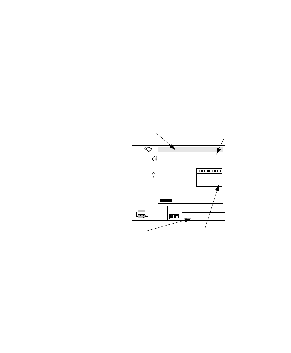
Entering Trend Scroll
1
What Data Will I See?
Stored Data
US
50
240
150
110
1
7
150
6
TOCO
20
100
(5)
cm/min
30
5
0
3
3
JANE DOE 194848
16:30:12 2/14/2001
4
32
1. Trend scroll mode “on” indicator.
2. ID of patient whose trend data is being reviewed (you may scroll to a
patient other than the patient currently being monitored).
3. Time and date when data values shown at reference line were recorded.
4. Toco value at reference line.
5. Vertical reference line centered in the Toco trend frame.
6. Vertical reference line centered in the heart rate trend frame.
7. FHR value at reference line.
The lines, (5 and 6) centered in the FHR and Toco trend frames, are the
reference points through which Toco and FHR values pass as the data scrolls
through the display.
52 Using Trend Scroll
Page 63

Entering Trend Scroll
1
Current Data When you are in trend scroll mo de you will still see important (unscrolled)
numeric data for the current monitoring session.
1
2
1. FHR of current monitoring session
2. Toco value of current monitoring session
3. Current communications status
4. Current power status
Printing a Trend Section
While in trend scroll mode you can mark the start and end boundaries of a
section of trend and print it. Ensure that you have a printer or the recorder
attached when you request a print.
US
50
TOCO
20
150
110
100
(5)
cm/min
240
150
30
0
3
3
JANE DOE 194848
16:30:12 2/14/2001
34
1. While in trend scroll mode, press the navigation wheel. The monitor
displays the Mark Print Boundary menu.
2. Choose “Yes” to accept the time at the center of the screen as the first
boundary of the section you want to print.
3. Rotate the wheel to scroll through the trend until the time at the center of
the screen represents the second boundary of the section you requir e. Take
care that this is still within the same patient fetal trace.
4. Press the wheel again to display the Mark Boundary and Print menu.
Using Trend Scroll
53
Page 64

Entering Trend Scroll
5. Select Yes to mark the second boundary and send this to the printer or
recorder. If you press “Clear Boundary” now, the first boundary marker is
cleared, allowing you to reset it.
Exiting Trend Scroll Mode
Press the trend scroll button a second time to leave this mode. The monitor
automatically returns to the main monitoring screen if you do not touch the
navigation wheel for 30 seconds.
54 Using Trend Scroll
Page 65

Printing and Transmitting Records
This chapter tells you how to transmit fetal traces from the monitor to
• the monit or’s own recorder
•a PC printer
• a system, suc h as OB TraceVue or a PC running FM-2 viewer utility
software.
Setting up the Modem
Before you can transmit fetal traces to a remote system you need to install, setup
and initialize an approved modem at the monitor, and also at the remote system.
8
Number to Dial
Into the monitor you must program the telephone number of the remote modem
it must contact. If you transmit to only one remote modem, you will only need to
enter this number only one time. However, if you dial a variety of remote
modems, you must set this each time you want to dial a different modem.
1. Select Communications Menu -> Number to Dial.
2. In the “Set Phone Number” window, turn the navigation wheel to
highlight the first character position and press to select. Rotate the
navigation wheel to cycle through the available characters and digits for
this position. Press the wheel to fix your chosen digit.
3. Move to the next position and repeat, until the complete telephone number
is entered.
4. Select “OK
Printing and Transmitting Records 55
Page 66

Setting up the Modem
1
Modem Initialization
For full details, see the FM-2 Service Guide.
Default Initiali-
zation String
Pulse/Tone
Dial
Local Branch
Exchange
FM-2 uses the modem’s default values. If data transfer works with these, then
you do not have to enter any modem initialization string.
1. Select Communications Menu -> Modem Initialization.
2. If you need to enter any initialization data, the procedure is the same as
described for entering the modem telephone number.
A telephone system may use either pulse, or tone, dialling. The modem needs to
know which. If the modem’s default value is not appropriate for your telephone
system, you will have to change it. Enter either “P” for pulse, or “T” for tone in
the modem initialization string, as appropriate for your system.
The modem expects a public line with a continuous tone. If you use a local
branch exchange, this might not occur. Therefore you should enter “X0” (this is
known as the ‘blind dial’) in the initialization string.
Communications Menu
US
50
TOCO
20
Communications Menu
Data Transfer Stopped
Destination
Set Mode m Init String
Paper Output
Paper Speed
TX
Paper Style
Modem Initialization
Number to Dial
Return
(5)
cm
3
min.
0
OK Cancel Clea r
JANE DOE 194848
16:34:12 2/14/2001
Printer/Record er
Current Reco rd
(3 cm/min)
Set Modem
Initialization String
entering tone dialling (T), and blind dial (X0)
56 Printing and Transmitting Records
Page 67

Printing and Transmitting Records
You can print realtime to the recorder, or to an OB TraceVue system. You
cannot print realtime to a printer, or to FM-2 viewer. You cannot simultaneously
print a paper trace and link realtime to OB TraceVue.
A fetal trace is never deleted from the monitor after transmission or
retransmission. The only way a fetal trace is erased from the monitor is if the
memory space is needed by the current monitoring session. The current fetal
trace gradually overwrites the oldest fetal trace completely.
Process Overview
The steps are
1. Choose Paper Output Type (recorder/printer only)
2. Choose Output Destination
3. Start Data Transfer
4. Choose which records to transfer (system batch, FM-2 viewer, patient
records only).
Printing and Transmitting Records
Note—The monitor ignores any choice that is not appropriate for the task you
are performing (for example, if you choose “System Batch” the monitor will
ignore all “Paper Output” settings).
Choosing
Paper Output
Type
Printing and Transmitting Records
For output to the printer or recorder, you need first to specify what type of
printed output you require. Select Communications Me nu - > P aper Output.
Choose from:
Summary list a list of all stored patient IDs (available for printer
only).
Current Record print the current patient fetal trace, realtime, on the
recorder, from now until data transfer stops
(available for recorder only).
Patient Records one or more patient fetal traces (available for both
printer and recorder).
57
Page 68

Printing and Transmitting Records
Choosing Out-
put Destina-
tion
After choosing the printed output type, you must specify a destination. For all
other types of output, you only have t o specify th e output destination. Select
Communications Menu -> Destination. Choose from:
Printer/Recorder • use with “summary list”, “current record” or
“patient records”.
FM-2 viewer • use to send stored fetal traces either directly, or
via a modem, to FM-2 viewer software. With a
modem connection, the destination phone is
automatically dialled before the first fetal trace
is transferred and hung up after the completion
of the final fetal trace transfer.
System Online • send the current patient fetal trace, realtime, to
OB TraceVue, from now until data transfer
stops. Note that a simultaneous printed trace
output is not possible with this choice.
System Batch • use to send stored fetal traces to OB TraceVue
via a modem link. The destination phone is
automatically dialled before each fetal trace is
transferred and hung up after the completion o f
each transfer.
58 Printing and Transmitting Records
Page 69

Printing and Transmitting Records
1
Starting the
Transfer
After choosing the destination, you must start the transfer. Select
Communications Menu -> Data Transfer and then “Yes” to start the transfer.
Select “Data Transfer”
US
50
TOCO
20
(5)
3
Communications Menu
Data Transfer
Destination
Paper Output
Paper Speed
Modem Initialization
Number to Dial
Return
cm
min.
Start Data Transfer?
Yes No
Yes
JANE DOE 194848
16:34:12 2/14/2001
select “Yes” to start data transfer
Stopped
Printer/Recorder
Current Record
(3 cm/min)
Printing and Transmitting Records
59
Page 70

Printing and Transmitting Records
1
Choosing
Which Fetal
Traces
When you choose “Patient Records”, “System Batch”, or “FM-2 viewer” the
monitor prompts you with the ID of the most recent patient
Communications Menu
US
50
TOCO
20
(5)
Communications Menu
Data Transfer Stopped
Destination System Batch
Paper Output Patient Rec ords
Paper Speed 3 cm/min
Print JANE DOE 194848?
Paper Style USA
Modem Initialization
Modem Number To Dial
Return
3
cm/min
No All CancelYes
No All
JANE DOE 194848
16:34:12 2/14/2001
(3 cm/min)
(U.S.)
1978555122
abc d
You can choose:
a. Yes: print/transfer this fetal trace.
b. No: do not print/transfer this fetal trace, display next patient ID.
c. All: print/transfer current patient fetal trace and all subsequent
patient fetal traces.
d. Cancel: return to the Communications Menu.
During realtime printing on the recorder, or realtime monitoring on OB
TraceVue, if the communication is interrupted, the monitor tries to re-establish
communication once the problem is cleared.
60 Printing and Transmitting Records
Page 71

Communication Status
Printing and Transmitting Records
Communica-
tion status
You see this when... Comments Port
...the monitor has successfully
detected its modem an d i s tr yi n g t o
connect with another modem
...the modem successfu lly c onnect s
with another modem
...the monitor detects that a PC is
connected to the commu n ications
port
...the monitor is starting to print at
the recorder.
The data transfer dialog box shows the dialing number,
and dialing starts au to matically. You will he ar t he dial
tone, and dialing process fro m the modem speaker.
Transfer occurs automatically when the monitor and
remote computer are connected. The data transfer dialog
box shows the ID of the fetal trace bein g transferred, the
total number of traces for transfer, and th e percentag e o f
the transfer that has already happened. Each fetal trace
contains an integrity check. If it fails the check, the fet al
trace is automatically retransmitted. If it fails a second
time, the monitor displays a warning m essa ge and c an cels
the transfer.
The monitor and external PC can communicate directly
with each other. If a sla sh appears through the PC this
means that communication has been interrupted. The slash
will go away when communication resumes.
The icon is d isplayed when data transfer is initiated. The
icon is accompanied by the present setting for the print
speed. When it flashes, this indicates that the device needs
attention, for exampl e when the paper is low or runs out,
or if the monitor detects a recorder error. If a slash appears
through the PC this means that communication has been
interrupted. The slash will go away when communication
resumes.
Serial
Serial
Serial
Parallel
...the monitor is starting to print at
the printer.
The icon is d isplayed when data transfer is initiated. The
icon is accompanied by the present setting for the print
speed.
Parallel
Printing and Transmitting Records
61
Page 72

Recommended Modem s and Printers
Recommended Modems and Printers
These have been tested and are supported by Agilent. The list is correct at time
of print, but the list of recommended modems and printers may be revised or
updated periodically. Check with you r l ocal Res pon se C e nter i f y ou n eed further
details.
Modems
Multi-Tech MT-5600ZDX (use modem’s default initialization string)
Nokia 6210 cellular phone modem.
Printers
HP DeskJet 640c
HP DeskJet 840c
HP Deskjet 990Cxi
62 Printing and Transmitting Records
Page 73

Communications
Serial Port Communications
The monitor has an RS232 interface port for communications to:
• a modem
• a cellular telephone modem
• a PC/AT computer.
The RS232 communications protocol supports:
• direct connection to OB TraceVue
• direct patient data transfers to FM-2 viewer
• communications with a Nokia 6210 cellular phone modem
• communications with a MultiTech systems model MT-5600ZDX modem.
Parallel Port Communications
The monitor has a PC parallel port for communications with
Communications
•printer
• FM-2 (M2925A) recorder
Printing and Transmitting Records
63
Page 74

Communications
Cabling
Recorder
M2925A
Printer
Printer Cable
HP C2951A
Printer cable
(eg HP C2951A)
FM-2 Fetal
Monitor
M2922A
Direct link RS-232
9P female - 9P female
null-MODEM cable
Direct link RS-232
9P female - 9P female
null-MODEM cable
OB TraceVue
Client or other
system
FM-2 viewer
software
M2926A
(running on
PC)
Modem
AT Serial MODEM cable
25P Male - 9P Female
3 ft minimum
64 Printing and Transmitting Records
Page 75

Cable to.... Comments
...Recorder Comes with recorder.
Replacement can be ordered under: HP C2951
or replaced with PC parallel printer cable (conforming to IEEE
1284)
...Printer Might come with printer or buy locally.
Replacement can be ordered under: HP C2951A
or replaced with PC parallel printer cable (conforming to IEEE
1284)
...OB TraceVue client Order OB TraceVue M1380C option K10
...PC running FM-2 viewer Comes with FM-2 viewer software.
...Modem Comes with modem
(if not, locally source 25P Male -9P female, minimum length 3ft)
Communications
...Cellular telephone with
supporting-modem capability
Comes with cell phone.
If not, source 25P Male - appropriate cell phone connection from
cell phone manufacturer or other supplier.
Printing and Transmitting Records
65
Page 76

Communications
66 Printing and Transmitting Records
Page 77

Monitor
9
Cleaning
This chapter tells you how to care for your system.
WarningWarning
Unplug the monitor and recorder from the AC power source and detach all
accessories before cleaning. Do not immerse the monitor in water or allow
liquids to enter casing.
Caution
Take extra care when cleaning the display surfaces, which are sensitive to rough
handling. Rub the lens that covers them with a soft, dry cloth.
Keep the external surface clean and free of dust, dirt and residual liquids. Clean
with a damp cloth using mild soap and water or hospital approved, non-abrasive
disinfectants.
Cleaning 67
Page 78

Transducers (Cleaning and Low Level Disinfection)
Transducers (Cleaning and Low Level Disinfection)
Before starting cleaning or disinfection, carefully review the technical
information and follow all the precautions for use, safety, storage and disposal
of the cleaning and disinfecting agents as listed by their manufacturers.
For devices intended for use on immunocompromised patients, use sterile water
for rinsing and a sterile towel for drying the device during the cleaning and
disinfection process.
The Blue Ultrasound and Toco transducers are protected against the effects of
continuous immersion in water according to IEC 529 IP 68.
Do not:
• immerse a transducer in water when it is connected to the monitor if the
monitor is running on AC power.
• handle transducers roughly. This could damage the cover, piezoelectric
crystals and mechanical movement. Transducer covers are made of soft
plastic; avoid contact with hard or sharp objects.
• flex the cables excessively.
• allow cleaning solutions or transducers to exceed a temperature of 45
• autoclave the transducers and cables or heat them above 70
• permit the Toco transducer’s ventilated cable connector to become wet as
o
(113
F).
liquid can enter the ventilation tube through capillary action.
o
C (158oF).
o
C
Caution
Do not immerse the transducer connectors during any stage of the cleaning/
disinfection process.
Caution
Do not autoclave. Do not gas sterilize.
The following cleaning and low level disinfection procedures have been
validated.
68 Cleaning
Page 79

Transducers (Cleaning and Low Level Disinfection)
The cleaning procedure will be more effective in reducing contamination if
cleaning is done prior to drying of adherent visible soil (for example, organic
matter or other debris) on the transducer.
Do not reuse alcohol for disinfection. Cidex
instructions).
Cleaning and Disinfecting
® is reusable (see manufacture’s
Cleaning
1. Clean the transducer thoroughly using potable tap water and then a cleaning agent such as an
enzymatic detergent. Prepare the detergent as recommended by its manufacturer. Scrub the
transducer in the detergent using a soft bristled brush for five (5) minutes.
2. Rinse the device with clean tap water for at least one (1) minute to remove detergent.
3. Visually inspect the transducer. If adherent soil is still present, repeat step s 1 and 2.
4. Dry the transducer thoroughly with a clean, soft towel.
Disinfecting
Use only one agent for disinfecting at any given time.
Using 70% Isopropanol
a
Using Cidex®
5. Submerge the transducer in 70%
Isopropanol for a minimum of ten (10)
minutes, but not more than thirty (30)
minutes.
Cleaning
5. Submerge the transducer in activated 2.4%
Glutaraldehyde solution (Cidex®). Prepare the
solution according to the manufacturer’s
recommendations. Soak the transducer in the
solution for a minimum of ten (10) minutes, but no
more than thirty (30) minutes at 20-25
°C.
69
Page 80

Transducers (Cleaning and Low Level Disinfection)
Cleaning and Disinfecting
6. Rinse the transducer with potable tap
water, ensuring that all parts are in contact
with the water, for at least one (1) minute
to remove residual alcohol.
6. Rinse the device by immersing it in three separate
copious volumes of potable tap water. Each rinse
should be a minimum of one (1) minute in duration.
Use fresh portions of water for each rins e. ( Residues
of Cidex® that remain on the transducer may cause
adverse reactions such as skin irritation in the
patient.)
7. Dry the transducer thoroughly with a clean soft towel.
8. Follow your facility's post-processing handling procedures to eliminate or minimize
recontamination of the device before reuse. Contact your facility's Infection Control Office or
Epidemiologist for information regard i ng su ch procedu res .
a. For more information regarding cleaning agent compatibility, refer to the instructions/information supplied by the manufacturer.
The following disinfecting brands are believed to be compatible with the
materials of the transducers described in this manual. However the performance
of these disinfectants has not been validated for use with the transducers
described here.
Aldehyde-based
Buraton liquid
Gigasept®, Kohrsolin
®
, dilution of formaldehyde (3-6%),
®
Alcohol-based
Ethanol 70%, Cutasept
forte, Sagrosept
®
®
, Hospisept®, Kodan®-Tincture
, Spitacid®, Sterilium fluid
®
70 Cleaning
Page 81

Cleaning Belts
Cleaning Belts
Wash soiled belts with soap and water.
Recorder
Caution
Water temperature must not exceed 60
WarningWarning
Unplug the recorder from the AC power source and detach all accessories
before cleaning. Do not immerse the recorder in water or allow liquids to
enter the case.
Clean the print head at least once a year or more often if necessary. Wipe the
printhead and roller with a cottonbud soaked in isopropyl alcohol.
o
C (140oF).
Cleaning
71
Page 82

Recorder
72 Cleaning
Page 83

10
Using the Recorder or Printer
This chapter tells you how to install, set-up, and use the optional recorder
(M2925A) and how to connect the monitor to a recommended printer.
In an antepartum environment, you can stand the monitor on top of, or close to
the recorder for printing realtime. In a shared-recorder configuration where
several monitors are used without a recorder, the monitors containing stored
fetal traces collected from monitoring session(s) are brought to the printer for
printing at a later time.
WarningWarning
Disconnect the printer or recorder from the AC power before connecting
them to the monitor.
Caution
General purpose personal computers, printers and modems are not designed to
meet the electrical safety requirements of medical devices. Connect them with a
cable of sufficient length to locate them outside of the patient vicinity. This
means a minimum distance of 1.5 meters from the patient’s bed or chair. Do not
connect the FM-2 recorder to the monitor at the same time as a non-medical
device (computer, printer or modem) if the recorder is located in the patient
vicinity. For additional information refer to IEC/EN Standard 60601-1-1.
Using the Recorder or Printer 73
Page 84

Working with the Recorder
Working with the Recorder
Installing the Recorder
Place the recorder on a solid surface. Connect the communications cable to the
connector at the back of the recorder, marked . Connect the other end to
its mating connector at the back of the monitor .
Attach the AC line cord to the IEC receptacle at the back of the recorder.
Connect the other end to an appropriate AC outlet.
WarningWarning
The power receptacle must be a three-wire grounded outlet. Never adapt
the three-prong plug from the power supply or accessory to fit a two-slot
outlet. If the outlet has only two slots, make sure that it is replaced with a
three-slot grounded outlet before attempting to operate the monitor.
WarningWarning
Do not connect to an electrical outlet controlled by a wall switch
74 Using the Recorder or Printer
Page 85

Loading Paper
Working with the Recorder
WarningWarning
SHOCK HAZARD: Do no attempt to connect or disconnect a power cord
with wet hands. Make certain that your hands are clean and dry before
touching a power cord.
The printer is configured for Philips fetal monitor paper. Do not use paper from
any other manufacturer. It might damage the printer.
1. Unwrap the paper.
2. With the printed grid visible, unfo ld o ne p a ge from t he to p o f t h e pack and
lay it forwards across the top of the paper drawer. Make sure the Toco
grid area is closest to the recorder keys.
3. Slide the paper into the paper tray:
4. Slide the paper drawer into the recorder.
Annotating Paper
Some types of pens may distort the paper. It is advisable to try out the pen on a
piece of the same type of recorder paper.
Using the Recorder or Printer
75
Page 86

Working with the Recorder
Use only the following types of paper:
Product
Number
M1910A USA/Canada 30-240 Orange No Yes
M1911A International 50-210 Green Yes No
M1913A Interna-
a. Not available in Europe. Used mainly in Japan.
Storing Recorder Paper
Recorder paper is not intended for long-term archival storage. Another medium
should be considered if this is required.
Dyes contained in thermal papers tend to react with solvents and other chemical
compounds that are being used in adhesives. If these compounds come into
contact with the thermal print, the print may be destroyed over time. Y ou can take
the following precautionary measures to help avoid this effect.
• Store the paper in a cool, dry and dark place.
• Do not store the paper at temperatures over 40°C (104°F).
• Do not store the paper where the relative humidity exceeds 60%.
• A void intensive light (UV light), as this may cause the paper to turn gray or
the thermal print to fade.
• Avoid storing the thermal paper in combination with the fol lowi ng
conditions:
– Papers that contain organic solvents. This includes papers with
– Carbon paper and carbonless copy paper.
– Products containing polyvinyl chlorides or other vinyl chlorides for
– Detergents and solvents, such as alcohol, ketone, ester and others,
– Products containing solvent-based adhesives such as (but not
Country
FHR
Scale
Color
of Grid
kPa
Scale
Highlighted
3cm Lines
50-210 Green No Yes
a
tional
tributyl and/or dibutyl phosphates, for example recycled paper.
example (but not exclusively) document holders, envelopes, letter
files, divider sheet s.
including cleaning and disinfecting agents.
exclusively) laminating film, transparent film or labels sensitive to
pressure.
76 Using the Recorder or Printer
Page 87

To ensure long lasting legibility and durability of thermal printouts, store your
documents separately in an air-conditioned place and use
• only plasticizer-free envelopes or divider sheets for protection.
• laminating films and systems with water-based adhesives.
Using such protective envelopes cannot prevent the fading eff ect caused by other ,
external agents.
Using the Recorder
Connect the recorder to the monitor. Switch the recorder on using the AC switch
on the rear of the recorder. An LED on the front confirms that the recorder is
attached to an AC source and powered on.
Enable the recorder using:
1. Select Communications Frame
2. Select Communications menu -> Destination -> Printer/Recorder. The
3. Select Paper Output -> Current Record (or Patient Records)
4. Select Data Transfer -> Start Data Transfer? -> Yes
See “Printers” on page 62 for full details of how to select which fetal traces to
transfer.
Working with the Recorder
recorder icon displays in the Communications frame.
Check that the recorder is feeding paper and the power on test pattern prints
properly.
Using the Recorder or Printer
77
Page 88

Working with the Recorder
As you monitor a patient, the trace is automatically printed on the trace paper
key/icon Use this... Comments
Paper advance
Printing
Enable/Disable
Power-on
Indicator
...to fast forward the
recorder paper
...to toggle recorder mode
between printing and
standby
...to check that the recorder
is ready to print.
Press and hold to advance paper at high speed
(approximately 30 cm/minute) until you release the
button.
Any text and graphics being printed during paper
advance are lost. Printing resumes when you release
the button.
The indicator LED next to the button is lit when
printing is enabled. Printing is enabled by default
when you switch the monitor on.
It flashes when the paper runs out.
This is NOT a power on/off switch. That is located on
the rear of the recorder.
This indicator is lit when the monitor is connected to
an AC line source, and the mains switch on the rear of
the recorder is on.
78 Using the Recorder or Printer
Page 89

Working with a Printer
Use a printer that is supported by Philips; other printers may give incomplete
printouts, or may not work at all.
Connecting a Printer to the Monitor
Connect the printer to the 25 pin connector on the monitor, marked .
Always follow the manufacturer’s instructions for setting up and using your
printer.
Using a Printer
You cannot use the printer in realtime mode, only for printing out traces stored
in the monitor, or a list of stored fetal traces, showing patient ID. The printout
mimics the data from the recorder.
Working with a Printer
Using the Recorder or Printer
79
Page 90

Example Trace
Example Trace
You can print a fetal trace directly during monitoring to the recorder or, later
from stored data, to a printer.
Monitor
details
FHR traces (twins monitoring - FHR1
is the darker of the two traces)
Patient ID, time, and date
monitoring
mode and
legend
twins separation on
A trace may show:
• FHR and Toco traces
• Clinician and patient markers
• Paper speed
• Paper style, US or International (on recorder-trace only)
• Time and date
80 Using the Recorder or Printer
event markers
Toco trace
Page 91

Example Trace
• Installation or removal of a second ultrasound transducer
• Ultrasound trace separation
• Toco baseline value change
• Toco baseline adjust
• Patient ID
• Monitor software rev i sion
• US1, US2, Toco and legend, depending on whether the transducer is
attached or removed.
Each time you press print enable, the following header information appears
(recorder only)
• Present time and date
• US1, US2, Toco and legend, if transducer is attached.
• Paper speed
• Paper style - US or International (on recorder-trace only)
• Patient ID
Using the Recorder or Printer
81
Page 92

Example Trace
82 Using the Recorder or Printer
Page 93

Maintenance and Performance
Preventive Maintenance
The monitor requires a new battery at least every two years, or sooner if the
performance does not meet your expectation. After changing the battery, the
monitor requires tests as specified in the Service Guide. Only qualified service
personnel may change the battery.
There are no user serviceable parts within the monitor, only qualified service
personnel are permitted to service or repair the monitor.
Calibration and Adjustment
11
Assurance
The monitor, recorder and accessories require no calibration and adjustment.
Maintenance and Performance Assurance 83
Page 94

Performance Assurance
Performance Assurance
Testing the Monitor and Recorder
When any of the events listed in this table occur, you must perform the
appropriate test. The tests are detailed below.
Event Required Test(s)
Monitor installation Visual and monitor power-on tests
Monitor reinstallation (after
repair)
Recorder installation Visual and recorder power-on tests
Power supply replacement
Visual Test Visually inspect the monitor and accessories before use to ensure that the
monitor, cables, line cords, transducers and instruments have no visi ble evidence
of damage that may affect patient safety or monitoring performance. Do not use
if there is any visible sign of damage.
Monitor
Power-on Test
When you press , the monitor plays a power-on tone sequence while
performing a power-on test. It displays a startup screen showing revision
information about the software release. In less than 15 seconds you will see the
monitoring screen. If the monitor fails its self test, it will display an error screen,
and monitoring functions will not be available. Remove the monitor from
service.
To check the monitor, (and recorder if applicable):
1. Check that the monitor and recorder are properly connected together.
2. Check that the recorder has paper loaded in it.
3. Connect the monitor to the power supply.
4. Turn on the monitor and the recorder.
Visual and monitor power-on tests
Power-on
84 Maintenance and Performance Assurance
Page 95

Performance Assurance
5. Check that the monitor successfully powers on, and displays the main
monitoring screen. If an error occurs, it will display the error screen.
Remove the monitor from service if this happens.
6. Check that the recorder is feeding paper, and that the power on test p attern
prints properly. Remove the recorder from service if this does not occur.
Recorder
Power-on Test
Check that the recorder is feeding paper and the power on test pattern prints
properly when you switch it on.
Error Handling If the monitor detects a problem, it displays an error screen, showing an error
reference number and discontinues monitoring. The error number is written into
the error log for diagnostic use by qualified service personnel .
If either of the two following error conditions occur, call your representative or
Response center for assistance.
• If an operational error occurs that the monitor cannot self-detect, it shuts
down. No warning tones or indicator lights occur.
• If a self-detectable error occurs, the monitor displays the error screen,
sounds an error tone, and discontinues all monitoring functio ns . Switch it
off and call a qualified service professional.
Checking the
Error Log
You can view the error log by selecting Power Status Frame. This displays the
Service Menu. Select “View Error Log”. The error log has eight lines and can
show up the most recent eight error types. The monitor keeps a count of errors
for each error category. You can have many errors of one type and it only
occupies one line in the error log. It also shows the date and time of the most
recent error. If the limit of eight errors is exceeded, the newest error replaces the
oldest.
The A/D values are diagnostic aids for qualified service personnel. They are
detailed in the Service Guide.
Maintenance and Performance Assurance
85
Page 96

Performance Assurance
Error Trouble-
shooting
Most errors have no user remedy and require qualified service personnel to
interpret them. However if you see:
• Error 10: try charging the battery.There is some possibility that charging
• Error 15:This is a non-fatal error that occurs from time to time. It is
Testing Transducers
Te sting an
Ultrasound
Transducer
If the following test fails, contact your Philips Service Engineer or Response
Center. Do not use a faulty transducer. Ideally, test with a different ultrasound
transducer to determine if it is the original transducer or the monitor that is
faulty.
To test an ultrasound transducer:
1. Switch on the monitor .
2. Connect the transducer to the first ultrasound (US) socket.
3. Increase the loudspeaker volume to an audible level.
4. Holding the transducer in one hand, gently tap the transducer surface with
5. You should hear a noise from the loudspeaker.
the battery could fix the situation, though normally a low battery is
indicated with the low power warning and forces a moni tor shutdown.
logged in the error log but not normally on the monitoring screen. The
only time a user would see this error is by examining the error log. It is
not necessary to call a service professional.
your finger. You may find it easier if you use a small amount of gel on
transducer surface.
Te sting a Toco
Transducer
86 Maintenance and Performance Assurance
If the following test fails, contact your Philips Service Engineer or Response
Center. Do not use a faulty transducer. Ideally, test with a different Toco
transducer to determine if it is the original transducer or the monitor that is
faulty.
To test a Toco transducer:
1. Switch on the monitor .
2. Connect the transducer to the Toco socket.
3. Zero the transducer, by pressing the Toco Baseline button
Page 97

4. Gently apply pressure to the button centered on the transducer’s face.
5. Check that the value on the display shows this change in pressure.
Disposing of the Equipment
Arrangements for the di spo sal o f your monitor, recorder, battery and t r ans ducers
at the end of their working life should conform to your country’s laws regarding
the disposition of equipment containing electrical parts. Adhere to all applicable
laws regarding disposal and recycling.
Disposing of the Equipm ent
Obtaining Technical Assistance
For technical information and assistance, call your Philips Response Center or
your local representative.
Maintenance and Performance Assurance
87
Page 98

Returning System Components
Returning System Components
Have all equipment serial numbers available when calling. You will find the
unit’s serial number on its rear panel.
To pack the unit for return, disconnect all transducers and cables. It is not
necessary to return the transducers, event marker, or power cord. Pack the unit
into its original shipping carton if available. If not, use a suitable carton with
appropriate packing material to protect the unit during shipping.
Supplies and Accessories Reordering Information
These part numbers and descriptions are correct at the time of printing, but may
be revised or updated subsequently. To re-order supplies for your monitor
contact your local representative or order via the internet at http://
shop.medical.philips.com/hsgstore/catalog/supplies_dept.asp
Supply/Accessory Part Number and Description
Ultrasound Transducer M1356A
Latex free.
Toco Transducer M1355A
Ultrasound transmission gel
a
88 Maintenance and Performance Assurance
Latex free.
40483A: water-soluble, box of 12 x 250ml bottles, shelf life
24 months maximum, 6 months minimum.
40483B: 5-liter refill containe r. She lf life 24 m ont hs
maximum, 6 months minimum
Page 99

Supplies and Accessories Reordering Information
Supply/Accessory Part Number and Description
Paperb for FM-2 Recorder
(M2925A)
Transducer Belts M1562A: Elastic, reusable, 1.3m (52”) brown, box of five
Transducer knob adapters M1356-43203: Pack of 3.
Belt buttons M1569A: Pack of 10.
Remote Event Marker 15249A.
Canvas Tote Bag M3919A: Canvas carrying bag with room for monit or a nd
M1910A: Z-Fold paper, 150 sheets per pack, 30-240 FHR
scale, Orange (USA), No kPA scale, 3cm hi ghl ig hted l ines,
Case of 40.
M1911A: Z-fold paper, 150 sheets per pack, 50-210 FHR
scale, Green (International) , kPA scale, no highlighted 3 c m
lines. Case of 40.
M1913A:Z-fold paper, 150 sheets per pack, 50-210 FHR
scale, Green (International), no kPA scale, highlighted 3 cm
lines. Case of 40.
belts. Contains latex.
M2208A: Foam, dispos able, 1.3m (52”), blue/pink, box of
100 belts (50 blue, 50 pink). Conta ins latex.
Latex free.
accessories.
GCX Wallmounting M3904A.
GCX Rollstand M3909A.
a. Use only the approved gel. Using ultrasound gel that is not approved
by Philips may reduce the signal quality and may damage the transducer.
This type of damage is not covered by warranty
b. Do not use pape r with s procket holes intende d for HP 8040A/ 8041A
fetal monitors as the trace may not be legible and a paper jam may occur.
Use only the approved paper.
Maintenance and Performance Assurance
89
Page 100

Response Center Contact Information
Response Center Contact Information
Country Telephone Phone Number Address
Australia (Toll free) 1800 033-397
Austria +43 1 25125 333
BENELUX (Belgium
& Netherlands)
Brazil 0-800-553-329
China (Toll free) 86-800-810-0038
from Belgium:+32-2-
404.9102;
from Netherlands:+31-20-
547.25.55
Medical Products Group
347 Burwood Highway
Forest Hill VIC 3151
AUSTRALIA
Dresdnerstrasse 81-85
1200 Vienna
Austria
Boulevard de la Woluwe 100
1200 Brussels
Belgium
Alameda Araguaia 1142
Alphaville - Barueri CEP 06455-0000
Sao Paulo, BRASIL
HP Building
No 2, Dong San Huan Nan Lu
Chaoyang District, Beijing
PR China
Finland +358-10-855.2455
France 01.64.53.50.00 1 Rue Galvani,
90 Maintenance and Performance Assurance
Piispankalliontie 17
02200 Espoo - Finland
F-91745 Massy Cedex, France
 Loading...