


Published by BB 0549 Service Audio Printed in the Netherlands Subject to modification 3139 785 31770
DVP5900/12/05/37/98/93
DVD Player
CLASS 1
LASER PRODUCT
1 Technical Specifications and Connection
Facilities ...................................................................
2
2 Measurements Setup, Service Aid &
Service Hints ...........................................................4
3 Directions For Use ...................................................8
4 Dismantling Instructions & Service Positions .........
10
5 Service Test Program ............................................
13
6 Block Diagram ........................................................
15
Wiring Diagram ......................................................
16
7 Circuit Diagram and PWB Layout ..........................17
Zoran Peak Design DVP5900 ................................ 17
Zoran Peak Design DVP5900 -
Layout (Top View) ..................................................23
Zoran Peak Design DVP5900 -
Layout (Bottom View) ............................................. 24
Front Board ............................................................
25
Front Board - Layout (Top View) ............................
26
Front Board - Layout (Bottom View) .......................
27
Standby Board .......................................................
28
Standby Board - Layout (Top View) .......................28
Standby Board - Layout (Bottom View) ..................
28
8 Exploded View & Spare Parts List .........................
29
Exploded View of the Set .......................................
29
Spare Parts List ......................................................
30
©
Copyright 2004 Philips Consumer Electronics B.V. Eindhoven, The Netherlands.
All rights reserved. No part of this publication may be reproduced, stored in a retrieval system or
transmitted, in any form or by any means, electronic, mechanical, photocopying, or otherwise without
the prior permission of Philips.
Version 1.0
Page
TABLE OF CONTENTS
GB

EN 2
3139 785 317701.
LOCATION OF PC BOARDS
Technical Specifi cations and Connection Facilities
VERSION VARIATIONS:
TYPE /Versions:
Features &
Board in used
Video (Yellow, Cinch)
Component Video, (Y/Pb/Pr) -P-scan
SCART (CVBS/RGB)
Coaxial Out
Line out (Audio)
HDMI
DVP5900
DVP5900
/05 /12 /37 /93 /98
x
x
x
x
x
x
x
x
x
x
x
x
x
x
-
x
x
x
x
x
-
x
x
x
x
x
-
x
x
x

Technical Specifi cations and Connection Facilities
1. Specifi cations
3139 785 31770
1.
EN 3
1.1 GENERAL:
Mains voltage : 120V for /37
220-240V for /05, /12
110-127V/220-240V for
/93, /98
Mains frequency : 50/60Hz
Power consumption : < 14W
< 3W at Standby mode
Dimension centre unit : 435 x 48 x 310mm
1.2 AUDIO PERFORMANCE:
Normal Mode Stereo L/R
Output Voltage : 2Vrms ± 1.5dB
Channel Unbalance (1kHz) : < 0.45dB
Crosstalk : > 90dB (1kHz)
> 70dB (16kHz-20kHz)
Freq. Response (20Hz-20kHz) : ± 1.0dB
Signal to Noise Ratio : > 90dB (A-weighted)
Distortion and Noise : < 80dB (1kHz)
1.3 AUDIO FORMAT:
MPEG/AC-3/PCM : Compressed Digital
16, 20, 24 bits
fs, 44.1, 48, 96 kHz
MP3 (ISO 9660) : 96, 112, 128, 256 kbps
& variable
bit rate fs, 32, 44.1,
48 kHz
1.4 VIDEO FORMAT:
Digital Compression : MPEG-2 for DVD,
SVCD
MPEG-1 for VCD
MPEG-4
DivX
1.5 VIDEO PERFORMANCE:
CVBS
YPbPr
RGB (Scart)
1)
: 1.0V
1)
: 0.7V
1)
: 0.7V
p-p
p-p
p-p
1)
Output terminals to be terminated with 75Ω

EN 4
3139 785 317702.
Measurements Setup, Service Aid & Service Hints
2. Measurements Setup, Service Aid & Service Hints
MEASUREMENT SETUP
Tuner FM
Bandpass
LF Voltmeter
e.g. PM2534
RF Generator
e.g. PM5326
DUT
250Hz-15kHz
e.g. 7122 707 48001
Ri=50Ω
S/N and distortion meter
e.g. Sound Technology ST1700B
Use a bandpass filter to eliminate hum (50Hz, 100Hz) and disturbance from the pilottone (19kHz, 38kHz).
Tuner AM (MW,LW)
RF Generator
e.g. PM5326
Ri=50Ω
DUT
Frame aerial
e.g. 7122 707 89001
Bandpass
250Hz-15kHz
e.g. 7122 707 48001
LF Voltmeter
e.g. PM2534
S/N and distortion meter
e.g. Sound Technology ST1700B
To avoid atmospheric interference all AM-measurements have to be carried out in a Faraday´s cage.
Use a bandpass filter (or at least a high pass filter with 250Hz) to eliminate hum (50Hz, 100Hz).
CD
Use Audio Signal Disc
(replaces test disc 3)
DUT
L
R
SBC429 4822 397 30184
S/N and distortion meter
e.g. Sound Technology ST1700B
LEVEL METER
e.g. Sennheiser UPM550
with FF-filter
Recorder
Use Universal Test Cassette CrO2 SBC419 4822 397 30069
or Universal Test Cassette
LF Generator
e.g. PM5110
Fe SBC420 4822 397 30071
DUT
L
R
S/N and distortion meter
e.g. Sound Technology ST1700B
LEVEL METER
e.g. Sennheiser UPM550
with FF-filter
Measurements Setup, Service Aid & Service Hints
SERVICE AIDS
Service Tools:
Universal Torx driver holder .................................. 4822 395 91019
Torx bit T10 150mm ............................................. 4822 395 50456
Torx driver set T6 - T20 ......................................... 4822 395 50145
Torx driver T10 extended ...................................... 4822 395 50423
Compact Disc:
SBC426/426A Test disc 5 + 5A ............................ 4822 397 30096
SBC442 Audio Burn-in Test disc 1kHz ................. 4822 397 30155
SBC429 Audio Signals disc .................................. 4822 397 30184
Dolby Pro-logic Test Disc ...................................... 4822 395 10216
3139 785 31770
2.
EN 5
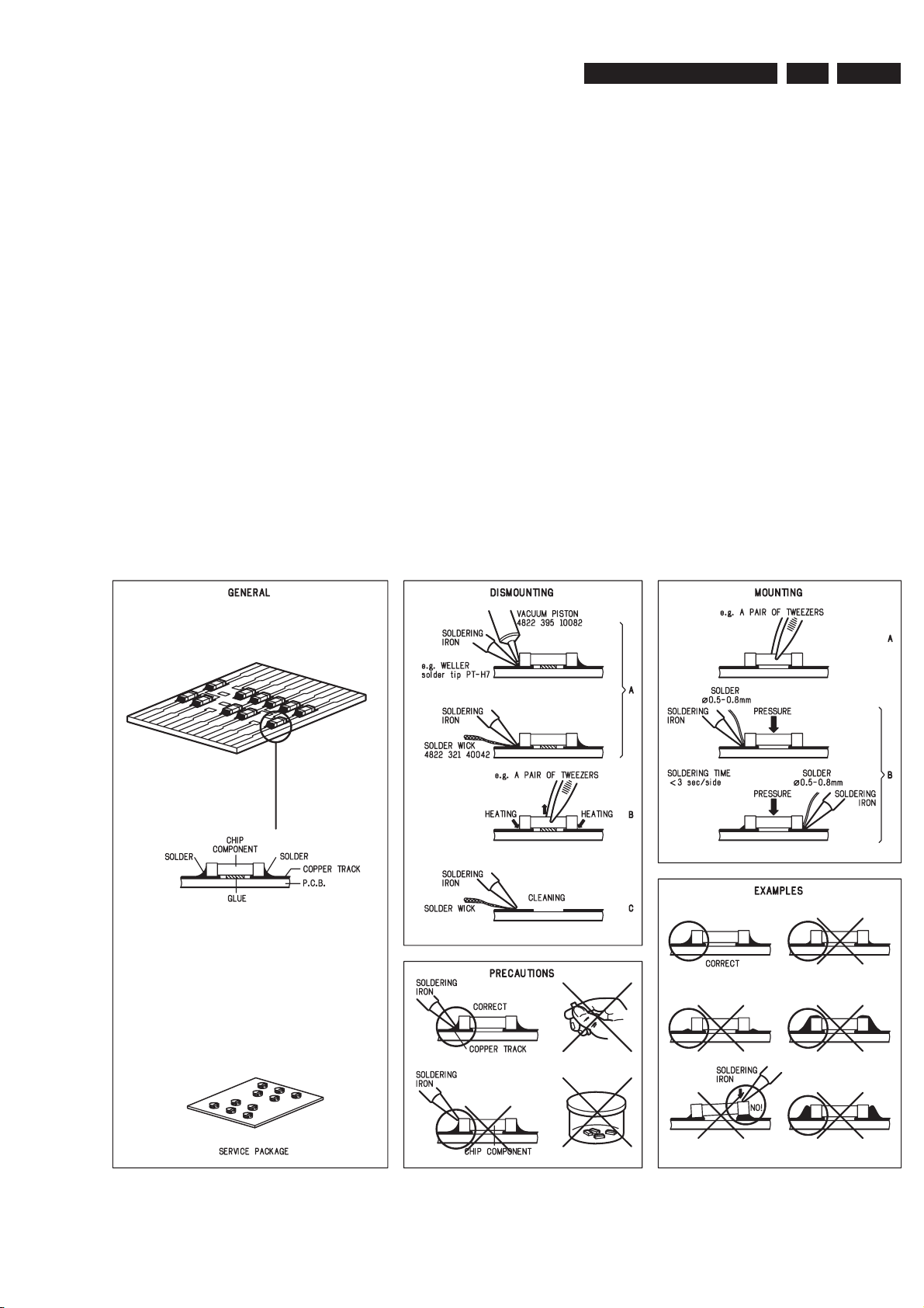
HANDLING CHIP COMPONENTS
EN 6
3139 785 317702.
Measurements Setup, Service Aid & Service Hints
GB
All ICs and many other semi-conductors are
susceptible to electrostatic discharges (ESD).
Careless handling during repair can reduce life
drastically.
When repairing, make sure that you are
connected with the same potential as the mass
of the set via a wrist wrap with resistance.
Keep components and tools also at this
potential.
Tous les IC et beaucoup d’autres
semi-conducteurs sont sensibles aux
décharges statiques (ESD).
Leur longévité pourrait être considérablement
écourtée par le fait qu’aucune précaution n’est
prise à leur manipulation.
Lors de réparations, s’assurer de bien être relié
au même potentiel que la masse de l’appareil et
enfiler le bracelet serti d’une résistance de
sécurité.
Veiller à ce que les composants ainsi que les
outils que l’on utilise soient également à ce
potentiel.
F
WARNING
ATTENTION
GB
Complete Kit ESD3 (small tablemat, wristband,
connection box, extention cable and earth cable) ...........4822 310 10671
Wristband tester ....................................................................4822 344 13999
ESD
D
WARNUNG
Alle ICs und viele andere Halbleiter sind
empfindlich gegenüber elektrostatischen
Entladungen (ESD).
Unsorgfältige Behandlung im Reparaturfall kan
die Lebensdauer drastisch reduzieren.
Veranlassen Sie, dass Sie im Reparaturfall über
ein Pulsarmband mit Widerstand verbunden
sind mit dem gleichen Potential wie die Masse
des Gerätes.
Bauteile und Hilfsmittel auch auf dieses gleiche
Potential halten.
ESD PROTECTION EQUIPMENT:
NL
Alle IC’s en vele andere halfgeleiders zijn
gevoelig voor electrostatische ontladingen (ESD).
Onzorgvuldig behandelen tijdens reparatie kan
de levensduur drastisch doen verminderen.
Zorg ervoor dat u tijdens reparatie via een
polsband met weerstand verbonden bent met
hetzelfde potentiaal als de massa van het
apparaat.
Houd componenten en hulpmiddelen ook op
ditzelfde potentiaal.
Tutti IC e parecchi semi-conduttori sono
sensibili alle scariche statiche (ESD).
La loro longevità potrebbe essere fortemente
ridatta in caso di non osservazione della più
grande cauzione alla loro manipolazione.
Durante le riparazioni occorre quindi essere
collegato allo stesso potenziale che quello della
massa dell’apparecchio tramite un braccialetto
a resistenza.
Assicurarsi che i componenti e anche gli utensili
con quali si lavora siano anche a questo
potenziale.
WAARSCHUWING
I
AVVERTIMENTO
GB
Safety regulations require that the set be restored to its original
condition and that parts which are identical with those specified,
be used
Safety components are marked by the symbol
!
.
NL
Veiligheidsbepalingen vereisen, dat het apparaat bij reparatie in
zijn oorspronkelijke toestand wordt teruggebracht en dat onderdelen,
identiek aan de gespecificeerde, worden toegepast.
De Veiligheidsonderdelen zijn aangeduid met het symbool
!
F
Les normes de sécurité exigent que l’appareil soit remis à l’état
d’origine et que soient utiliséés les piéces de rechange identiques
à celles spécifiées.
Less composants de sécurité sont marqués
!
D
Bei jeder Reparatur sind die geltenden Sicherheitsvorschriften zu
beachten. Der Original zustand des Geräts darf nicht verändert werden;
für Reparaturen sind Original-Ersatzteile zu verwenden.
Sicherheitsbauteile sind durch das Symbol
!
markiert.
I
Le norme di sicurezza esigono che l’apparecchio venga rimesso
nelle condizioni originali e che siano utilizzati i pezzi di ricambio
identici a quelli specificati.
Componenty di sicurezza sono marcati con
!
CLASS 1
LASER PRODUCT
GB
Invisible laser radiation when open.
Avoid direct exposure to beam.
Osynlig laserstrålning när apparaten är öppnad och spärren
är urkopplad. Betrakta ej strålen.
SF
Avatussa laitteessa ja suojalukituksen ohitettaessa olet alttiina
näkymättömälle laserisäteilylle. Älä katso säteeseen!
DK
Usynlig laserstråling ved åbning når sikkerhedsafbrydere er
ude af funktion. Undgå udsaettelse for stråling.
S
Warning !
Varning !
Varoitus !
Advarse !
GB
After servicing and before returning set to customer perform a leakage
current measurement test from all exposed metal parts to earth ground to
assure no shock hazard exist. The leakage current must not exceed
0.5mA.
F
"Pour votre sécurité, ces documents doivent être utilisés par
des spécialistes agréés, seuls habilités à réparer votre
appareil en panne".

Measurements Setup, Service Aid & Service Hints
3139 785 31770
2.2 Service Hints
CAUTION
CHARGED CAPACITORS ON THE SERVO BOARD MAY DAMAGE THE DRIVE
ELECTRONICS WHEN CONNECTING A NEW DRIVE.THAT’S WHY, BESIDES THE SAFETY
MEASURES LIKE
• SWITCH OFF POWER SUPPLY
• ESD PROTECTION
ADDITIONAL ACTIONS MUST BE TAKEN BY THE REPAIR TECHNICIAN.
The following steps have to be done when replacing the defective loader :
1. Dismantling of the loader to access the ESD protection point if necessary.
2. Solder the ESD protection point*.
3. Disconnect fl exfoil cable from the defective loader.
4. Put a paper clip on the fl exfoil to short-circuit the contacts (fi g.1)
5. Replace the defective loader with a new loader.
6. Remove paperclip from the fl exfoil and connect it to the new loader.
7. Remove solder joint on the ESD protection point.
2.
EN 7
ATTENTION: The laser diode of this loader is protected against ESD by a solder joint which shortcircuits the laserdiode to ground.
Type 1 Type 2
(ESD protection point is accessible from top of loader) (ESD protection point is accessible from bottom of the loader)
*Only applicable for defective loader needed to be sent back to supplier for failure analysis and to support backcharging
evidence.
This is also applicable for all partnership workshops.
For proper functionality of the loader this solder joint must be remove after connection loader to the set.

EN 8
3139 785 317703.
Directions For Use
3. Directions For Use
The following except of the Quick Use Guide serves as an introduction to the set.
The Complete Direction for the Use can be downloaded in different languages from the internet site of Philips Customer care Center:
www.p4c.philips.com
DivX DVD Player
See, hear, play everything
with HDMI
Be impressed with this Philips DVD player with HDMI digital video and audio connection. Step into
another home entertainment arena as you immerse yourself with High Denition video (720p /
1080i).
Unrivalled video performance
• HDMI out for digital high-denition video and digital audio
• Video Upscaling for improved resolution of up to 1080i lines
• Displays high denition pictures (JPEG) in true resolution
Enrich your movie experience
• Progressive Scan for razor-sharp and icker free images
• 192kHz/24-bit audio DAC delivers high-quality audio
Plays it all
• Movies: DVD, DVD+R/RW, (S)VCD, DivX 3.11/4.x/5.x/6.x, MPEG4
• Music: CD, MP3-CD, CD-R/RW & Windows Media™ Audio
• Photos: Picture CD (JPEG)
DVP5900

Directions For Use
3139 785 31770
DivX DVD Player
Technical specications Product highlights
3.
EN 9
Picture/Display
• D/A converter: 10 bit, 54 MHz
• Picture enhancement: Progressive Scan, Video
upscaling, Video upsampling
Sound
• D/A converter: 192kHz/24-bit
• Signal to noise ratio: 108 dB
• Distortion and Noise (1kHz): 80 dB
• Crosstalk (1kHz): 100 dB
• Dynamic Range (1kHz): 94 dB
• Sound System: Dolby Digital, MPEG2, Stereo
• Sound Enhancement: Night Mode
Video Playback
• Disc Playback Media: CD, CD-R/CD-RW, Video
CD/SVCD, DVD, DVD-RW (Video mode),
DVD-R, DVD-Video, DivX, WMA, DVD+R/
+RW
• Compression formats: MPEG1, MPEG2, MPEG4,
XviD, DivX 3.11, DivX 4.x, DivX 5.x
Audio Playback
• Disc Playback Media: CD, MP3-CD, WMA, CDR/RW
• Compression format: Dolby Digital, MP3, PCM,
Windows Media (TM) Audio
• MP3 bit rates: 32 - 256 kbps
Still Picture Playback
• Disc Playback Media: Picture CD
• Picture compression format: JPEG
• Picture enhancement: Rotate, Zoom, High
Denition Resolution
Connectivity
• Other connections: HDMI out
• Audio Output - Analog: Stereo (Red/White
cinch)
• Audio Output - Digital: Coaxial (cinch)
• Video Output - Analog: Component RGB
(SCART), Composite CVBS (on SCART),
Component Y Pb Pr (cinch), Composite CVBS
(yellow cinch)
Convenience
• On-Screen Display languages: Danish, Dutch,
English, French, German, Italian, Norwegian,
Portuguese, Spanish, Swedish, Turkish, Polish,
Russian
Power
• Power supply: 100-240VAC, 50/60Hz
• Standby power consumption: < 3W
Accessories
• Batteries:
• Cables: None
• Remote control: 3141 017 90221
• User Manual: Danish, Dutch, English, Finnish,
French, German, Greek, Italian, Norwegian,
Portuguese, Spanish, Swedish, Turkish, Polish,
Russian
• Included batteries: 2x Longlife AA
Dimensions
• Packaging dimensions (W x H x D):
562 x 85 x 411 mm
• Weight incl. Packaging: 3.5 kg
• Set dimensions (W x H x D):
435 x 48 x 310 mm
• Set weight: 1.9 kg
HDMI
HDMI stands for High Denition Multimedia Interface.
It is a direct digital connection that can carry digital HD
video as well as digital multichannel audio. By
eliminating the conversion to analog signals it delivers
perfect picture and sound quality, completely free from
noise. HDMI is fully backward-compatible with DVI.
Video Upscaling
With Video Upscaling you can increase the resolution of
SD (Standard Denition) video signals that DVD uses to
HD (High Denition) so you’ll be able to see more
details thanks to a sharper, more true-to-life picture.The
resulting HD video output signal can be fed to an HD
display through HDMI (High-Denition Multimedia
Interface).
High denition pictures
With High Resolution JPEG playback, you can show up
to 2 Megapixel resolution on your FTV. Now you can
view your digital pictures in their true resolution, without
loss of quality or details.
Progressive Scan
Progressive Scan doubles the vertical resolution of the
image resulting in a noticeably sharper picture. Instead
of sending a eld comprising the odd lines to the screen
rst, followed by the eld with the even lines, both elds
are written at one time. A full image is created
instantaneously, using the maximum resolution. At such
a speed, your eye perceives a sharper picture with no
line structure.
192kHz/24 bit audio DAC
192KHz sampling enables you to have an accurate
representation of the original sound curves. Together
with a 24-bit resolution, more information is captured
from the original analogue sound wave form, giving a
much richer audio reproduction.
Multi-format Movies-DivX, MP4
Multi-format playability allows you to play most disc
formats for maximum compatibility and viewing
pleasure.
Music: Windows Media™ Audio
Multi-format playability allows you to play most disc
formats for maximum disc compatibility and listening
pleasure.
Picture CD (JPEG)
Multi-format playability allows you to view images in the
comfort of your living room and play most disc formats
for maximum disc compatibility and viewing pleasure.

EN 10
3139 785 317704.
4. Dismantling Instructions
Dismantling Instructions & Service Positions
4.1 Dismantling of the DVD Loader.
1) The tray can be manually open by inserting a minus
screw driver and push the lever in the direction as shown
in Figure 1 to unlock the tray before sliding it out.
2) Slide out the tray and remove the Tray Front
assembly as shown in Figure 2.
Figure 4-1
3) Loosen 5 screws to remove the Cover Top.
- 1 screw each on the left and right side
- 3 screws on the rear
4) Loosen 4 screws to remove the DVD Loader as shown in
Figure 3.
A
Figure 4-3
A
Figure 4-2

Dismantling Instructions & Service Positions
4.2 Dismantling of the Front Board, Zoran Board,
PSU Board.
3139 785 31770
4.
EN 11
1) Release 2 snap hooks on the sides to remove the Front
Panel.
2) Loosen 2 screws on the board and 4 screws at the rear of
the set to remove the Zoran Board.
B
Figure 4-4
3) Loosen 2 screws to remove the PSU Board.
D
Figure 4-6
C
Figure 4-5

EN 12
4.3 Service Positions
Front Panel Board
3139 785 317704.
Insulation Sheet
Dismantling Instructions & Service Positions
Zoran Board
Insulation Sheet
Service Position - Front Panel
Service Position - Zoran Board

5. Service Test Program
Service Test Program
3139 785 31770
5.
EN 13
To start service test program
hold
button depressed while
set is in standby and press the
STANDBY button*
Display shows the ROM
version “SVxx-yy”
MAIN MENU
DISPLAY
TEST
Button pressed?
Y
Display shows Figure 1 and
switch "Multichannel" &
"Progressive Scan" LEDs on
* Mains power to set must be on
Hold button depressed till the Display shown “SVxx-yy”
S refers to Service Mode
V refers to Version
xx refers to Software version number of the back uProcessor
(counting up from 01 to 99)
yy refers to the front uProcessor version number
(00 will be displayed if there is no front uProcessor use)
N
Figure 1
Button pressed?
Y
Display shows Figure 2 and
switch "Multichannel" &
"Progressive Scan" LEDs off
Button pressed?
Y
N
Figure 2
N
Various
other Tests
TEST Activated with ACTION
EEPROM FORMAT
TEST
to Exit
Load default data. Display shows “NEW”.
Caution!
All presets from the customer will be
lost!!
LEAVE SERVICE
TEST PROGRAM
Disconnect
mains cord

EN 14
3139 785 317705.
Service Test Program
5.1.1 Reprogramming of DVD version Matrix
After repair, the customer setting and region code may be lost.
Reprogramming will put the set back in the state in which it has left
the factory, ie. with the default setting and the allowed region code.
Model Region Region Code TV Type
DVP 5900/12 Europe 2 PAL
DVP 5900/98 AP 3 PAL
DVP 5900/93 China 6 PAL
DVP 5900/37 Nafta 1 NTSC
DVP 5900/05 UK/Ireland 2 PAL
To reprogram do as follows:
1) Power up the set.
2) Open tray by press “OPEN/CLOSE” button on the set or press
and hold “STOP” button on the RC.
3) Press the following buttons on the Remote Control:
<9> <9> <9> <9> <SUBTITLE> <0> ...........for DVP 5900/12,
DVP 5900/05
<9> <9> <9> <9> <SUBTITLE> <1> ...........for DVP 5900/51
<9> <9> <9> <9> <SUBTITLE> <3> ...........for DVP 5900/98
<9> <9> <9> <9> <SUBTITLE> <5> ...........for DVP 5900/93
<9> <9> <9> <9> <AUDIO> <7> .................for DVP 5900/37
4) The display shows ‘YYYY-ZZ’ and the tray will close.
YYYY = model number (eg. 0720, 3900, etc.)
ZZ = stroke version (eg. 00, 02, 05, etc.)
5.1.2 Procedure for check Software version
1) Power up the set.
2) Open tray by press “OPEN/CLOSE” button on the set or press
and hold “STOP” button on the RC.
3) Press “DISPLAY” button on the Remote control.
4) The TV screen will shows:
SD6.1 Vxx YYYY-ZZ P QQ
SERVO: GGGGGGGG REG:D
xx = version number
YYYY = model number (eg. 0720, 3900, etc.)
ZZ = stroke version (eg. 00, 02, 05, etc.)
P / D = region code
QQ = version number of front uProcessor
GGGGGGGG = version for servo code
5.1.3 Procedure to upgrade software
1) Power up the set.
2) Open tray by press “OPEN/CLOSE” button on the set or press
and hold “STOP” button on the RC.
3) Place upgrade CD-ROM onto tray and close.
4) The set will response and display the following:
- LOAD [After the disc is read, the tray will open for you to
remove the disc]
- ERASE
- WRITE
- ERROR [if upgrade is unsuccessful]
- UPG END -> PHILIPS [if upgrade is successful]
- DISC->CLOSE->LOAD [Tray will close indicating that the
upgrade process is completed]
5) The whole process should not take more than 5 minutes.
Caution: Do not unplug the set until upgrade is completed.
5.1.4 Trade Mode
Trade mode is a feature that will block all set keys when enabled.
It is for dealers to prevent customers from removing disc, changing
source etc using the set keys. Rotary and Remote Control (RC) keys
are still allowed in Trade mode.
To activate Trade Mode:
1) Power up the set.
2) Open tray by press “OPEN/CLOSE” button on the set
or press and hold “STOP” button on the RC.
3) Then press buttons <2> <5> <9> on the RC.
4) The display shows ‘TRA ON’ and the tray will close.
Trade Mode is now enabled.
To deactivate Trade Mode:
1) Power up the set.
2) Open tray by press and hold “STOP” button on the RC.
3) Then press buttons <2> <5> <9> on the RC.
4) The display shows ‘TRA OFF’ and the tray will close.
Trade Mode is now disabled.

EN 15
3139 785 31770
6
Block Diagram, Wiring Diagram
0095PVD margaiD kcolB
REDOCED GEPM
70763RZ
EVIRD ROTOM
R
S8885MA
F
R
O
M
O
P
U
tibM61
tibM61
MARDS
rotcennoC
oiduA
1027
1157
10372027
oiduA hc-2
1051
)noisivorp(
1011
3011
TE5834KA
IMDH
rotcennoC
1061
IMDH
WS OEDIV
BCP tracS
tuO oediVSBVC/rP-bP-Y
2011
740
4
0167
0117
moc dna nacs-Pstnenop
REDAOL
ELUDOM
REWOP
YLPPUS
revirD DFV
C2I
yalpsiD tnecseroulF muucaV
m-yeKaxirt
revieceR RI
f Vmalietn
reffuB
:ylppuS
ybtsV5+
V21+
V42-
DEL
ybdnatS
tceteD
DRAOB ONOM
DRAOB TNORF
-
6. Block Diagram

EN 16
3139 785 31770
6.
Block Diagram, Wiring Diagram
13
A
8910
13
1234 5
G
H
I
E
F
9 101112
G
H
56
7
6
J
1
F
E
D
C
B
11 12
A
B
C
D
6
7
8
9
8
J
234
7
I
1
10
11
2
3
4
5
2
3
4
5
6
1503
B11B-PH-K
1
2
B6B-PH-K
1XXX
1
7
8
9
WH02D-1
1104
1
10
11
12
2
3
4
5
66
7
8
9
B12B-EH-A
CN2021106
B12B-EH-A
1
10
11
12
2
3
4
5
12345
345
1011
1-D50HW
9
1-D50HW
0011
1
2
1234567
8
45678
9
7011
1-D90HW1-D90HW
2011
123
1
2
3
4
5
WH02D-1
1XXX
1
2
B5B-PH-K
1XXX
XXX1
A-KRTB-NMF42
1501
24FMN-BTRK-A
14
2
3
4
5
6
7
8
9
1
10
11
12
13
14FE-BT-VK-N
1106
2001
14FE-BT-VK-N
SET WIRING DVP5900
31392493315_2005-08-26
Wiring Diagram

EN 17
3139 785 31770
7
5
5
4
4
3
3
2
2
1
1
D D
C C
B B
A A
VID0
VID1
VID2
VID3
VID4
VID5
VID6
VID7
VCLKX2
TMDS_D2+
TMDS_D2-
TMDS_D1+
TMDS_D1-
TMDS_D0-
TMDS_CLK-
RESET-
HD_VDDDAC
HD_AVDDT33
HD_AVDDT18
HD_VDDPLL
HD_CLK
HD_DAT
SPDIF
CLOSE
OPEN
FS3
/AUDIO_RESET
TMDS_D0+
TMDS_CLK+
VSYNC
HSYNC
HOTPLUGHOTPLUG_F
HOTPLUG
DDCDAT
TMDS_D0+
TMDS_D2-
TMDS_D2+
TMDS_CLK-
TMDS_CLK+
TMDS_D0-
TMDS_D1-
HDMI5V
DDCCLK
A+12V
TMDS_D1+
GND
TMDS_CLK+
TMDS_D2-
TMDS_D0+
TMDS_CLK-
TMDS_D1-
TMDS_D1+
TMDS_D2+
TMDS_D0-
HDVCC33
HDVCC18
HDVCC33
HDVCC33
HDVCC18
HDVCC18 HDVCC33
TDMSGND
HD_AVDDT33
HD_AVDDT33
DSPVCC33
TDMSGND
HDMI5V
A+12V
HDMI5V
HDMI5V
A+12V
TDMSGND
DSPVCC33
HDVCC33
DSPVCC18
VID0
VID1
VID2
VID3
VID4
VID5
VID6
VID7
VCLKX2
RESET-
HD_CLK
OPEN
CLOSE
FS3
OSCOUT
VSYNC
HSYNC
GCLKA
HD_DAT
HDVCC18 HDVCC33
DDCCLK
A+12V
DDCDAT
DSPVCC33
DSPVCC33
HDVCC33
DSPVCC18
4385CS
SPDIF
FS1
FS2
/AUDIO_RESET
CCLK
CDTI
ZR36721
C272 & C179 should be nearby Pin48 & Pin54 of I77
Power for I77_AVDDT33
Please Note:
TDMSGND should be
connected to GND
at a single point.
HDMI_TYPE_A
Adjust pin current 3619
55 or 60uA 2.87K/1%
90uA 2.8K/1%
HDMI 5V.(4.95~5.05V)
TMDS:
Transition Minimized Differential Signaling
DDC signal Capacitance:
<50pF
3615
4.7K
3626
1K
+
2622
47uF/16V
7611
B1117-ADJ
ADJ/GND1OUT2
2IN3
OUT1
4
7606
2N7002
1
32
2609
0.1uF
3609
0R
3625
2.7K
3605
75R/1%
2614
0.1uF
+
2608
100uF/16V
5606
FB220R
7603 P SS8550
1
2 3
3612
4.7K
2615
0.1uF
3613
4.7K
2616
0.1uF
2610
0.1uF
5607 FB220R
2611
0.1uF
+
2602
100uF/16V
2612
0.1uF
2613
0.1uF
2607
0.1uF
3618
1K/1%
3602
75R/1%
3610
10K
5601 FB220R
2620
0.1uF
3611 75R
+
2606
100uF/16V
+
2604
100uF/16V
+
2621
47uF/16V
2601
0.1uF
3619
2.87K/1%
2605
0.1uF
5603 FB220R
7610
VIN[0]
1
VIN[1]
2
VIN[2]
3
VIN[3]
4
VIN[4]
5
VIN[5]
6
VIN[6]
7
VIN[7]
8
VDDIP
9
VDDC
10
VCLKx2
11
GNDC
12
GNDP
13
HSYNC/I2C_CFG0
14
FIELD/I2C_CFG1
15
VDDP
16
GPIO[9]
17
GPIO[8]
18
GPIO[7]
19
GPIO[6]
20
GPIO[5]21SPDIF/I2C_CFG222GPIO[15]23GNDP24GPIO[4]25VDDP26GPIO[3]27GPIO[2]28GPIO[1]29GPIO[0]30VDDC31HOTPLUG32GNDC33GNDP34SCL35SDA36GPIO[16]37GPIO[17]38CEC39VDDP
40
RESET-
41
VDDPLL
42
REFCLK
43
GNDPLL
44
AGNDT33
45
TXCN
46
TXCP
47
AVDDT33
48
TXDN0
49
TXDP0
50
AGNDT33
51
TXDN1
52
TXDP1
53
AVDDT33
54
TXDN2
55
TXDP2
56
AGNDT33
57
AGNDT1_8
59
AVDDT1_8
60
CSET
58
VREF
61
GNDDACBS
62
GNDDACP
63
RSET
64
VDDD
65
Y/G
66
Pr/R
67
Pb/B
68
GNDDAC
69
GNDC
70
H_SYNC
71
VDDC
72
V_SYNC
73
GNDP
74
GPIO[14]
75
VDDP
76
GPIO[13]
77
GPIO[12]
78
GPIO[11]
79
GPIO[10]
80
3624
1K
2603
0.1uF
3607 1 .8K
3606
430 ohm/1%
+
2623
47uF/16V
3617
3.3R/1W
3604
75R/1%
5610
NM
1
2
3
4
3601 3 92 ohm/1%
5609
NM
1
2
3
4
5602 FB220R
5611
NM
1
2
3
4
3608 1 .8K
7604
BC848
1
2 3
3614 NM N.C.
1601
HD port
TDMS_D2+
1
TDMS_D2_SHIELD
2
TDMS_D2-
3
TDMS_D1+
4
TDMS_D1_SHIELD
5
TDMS_D1-
6
TDMS_D0+
7
TDMS_D0_SHIELD
8
TDMS_D0-
9
TDMS_CLK+
10
TDMS_CLK_SHIELD
11
TDMS_CLK-
12
CEC
13
NC
14
SCL
15
SDA
16
DDC/CEC_GND
17
+5V
18
HOTPLUG
19
GND20GND21GND22GND
23
5608
NM
1
2
3
4
7605
2N7002
1
32
2619
0.1uF
PHILIPS_5900_V40_0805_pg6.eps 2005-08-04
7. Zoran Peak Design DVP5900 - HD Companion Chip
Circuit Diagram and PWB Layout

EN 18
3139 785 31770
7.
Zoran Peak Design DVP5900 - Memory
Circuit Diagram and PWB Layout
5
5
4
4
3
3
2
2
1
1
D D
C C
B B
A A
MEMAD15
MEMRD-
MEMAD14
MEMAD13
MEMAD12
MEMAD11
MEMAD10
MEMAD9
MEMAD8
VF
RESET-
MEMAD19
MEMAD18
MEMAD17
MEMAD7
MEMAD6
MEMAD5
MEMAD4
MEMAD3
MEMAD2
MEMAD1
MEMAD16
MEMDA15
MEMDA7
MEMDA14
MEMDA6
MEMDA13
MEMDA5
MEMDA12
MEMDA4
MEMDA11
MEMDA3
MEMDA10
MEMDA2
MEMDA9
MEMDA1
MEMDA8
MEMDA0
MEMRD-
MEMAD0
MEMWR-
MEMWR-
MEMDA[15:0]
MEMAD[19:0]
VF
IMEMAD19
AMEMAD19
SSRAMCS-
FLASHCS-
MEMCS1-
VF
MEMCS0-
DSPVCC33
GND
MEMAD0
MEMDA0
MEMDA1
MEMDA6
MEMDA5
MEMDA7
MEMDA4
MEMDA3
MEMDA2
MEMAD3
GND
MEMAD5
MEMAD16
MEMAD1
MEMAD10
MEMAD12
MEMAD18
MEMAD8
MEMAD7
GND
MEMAD14
DSPVCC33
MEMRD-
MEMDA8
MEMDA11
SSRAMCS-
MEMDA9
MEMDA10
MEMDA14
MEMDA15
GND
MEMDA12
MEMDA13
MEMAD6
MEMAD2
MEMAD17
MEMAD4
MEMAD19
MEMWR-
MEMAD15
MEMAD13
MEMAD11
MEMAD9
FLASHCS-
GND
DSPVCC33
DSPVCC33 D+5V
D+5V
MEMDA[15:0]
RESET-
MEMWR-
MEMRD-
MEMAD[19:0]
MEMCS1-
MEMCS0-
D+5V
DSPVCC33
D+5V
Flash speed <= 70 nS
A19
NC
NC
RY/BY#
BYTE#
Basic function: SST39VF800 is OK.
Without EEPROM.
Memory Choose
1302 Setup :
a)Flash memory(7301) : 1-3 short only
b)External SRAM( 1301) : 1-2 and 3-4 short.
In MP stage, install 3307 and not install 1302.
EXTERNAL SRAM PORT
+
2302
47uF/16V
1301
NM
1
2
3
4
5
6
7
8
9
10
11
12
13
14
15
16
17
18
19
20
21
22
23
24
25
26
27
28
29
30
31
32
33
34
35
36
37
38
39
40
41
42
43
44
45
46
47
3307 0R
3306 NM
4302
Jumper2.0X2
3
4
1
2
2307
100pF
3301
10K
2306
100pF
7301
M29W160ET70N6
A15
1
A14
2
A13
3
A12
4
A11
5
A10
6
A9
7
A8
8
NC
9
A20
10
WE#
11
RP#
12
VPP
13
WP#
14
A19
15
A18
16
A17
17
A7
18
A6
19
A5
20
A4
21
A3
22
A2
23
A1
24
A16
48
VCCQ
47
GND
46
DQ15
45
DQ7
44
DQ14
43
DQ6
42
DQ13
41
DQ5
40
DQ12
39
DQ4
38
VCC
37
DQ11
36
DQ3
35
DQ10
34
DQ2
33
DQ9
32
DQ1
31
DQ8
30
DQ0
29
OE#
28
GND
27
CE#
26
A0
25
3303
0R
3304
NM
2304
0.1uF
3305 0R
3302
10K
2301
0.1uF
2303
0.1uF
PHILIPS_5900_V40_0805_pg3.eps 2005-08-04

EN 19
3139 785 31770
Zoran Peak Design DVP5900 - ZR36778 & SDRAM
7
Circuit Diagram and PWB Layout
5
5
4
4
3
3
2
2
1
1
D D
C C
B B
A A
OSCIN
IRRCV
MEMDA8
DUPTD1
MEMDA7
RAMADD1
MEMDA15
RAMDAT14
RAMDAT3
MEMAD4
RAMDAT4
RAMADD3
MEMCS1-
MIRR
RAMCS-
RAMADD7
MEMDA9
MEMDA13
MEMAD16
RAMCKE
MEMAD5
RAMDAT2
RAMDAT8
MEMDA2
MEMDA11
STB_DET
MEMCS0-
MEMAD2
VSYNC
RAMWE-
OSCOUT
RAMDAT0
RAMCAS-
RAMRAS-
RAMADD0
MEMDA4
MEMDA12
MEMAD12
DSPVCC33
RAMDAT13
RAMDAT11
RAMDAT6
RAMADD9
RAMADD4
MEMAD6
MEMDA3
DUPRD1
RFA_SCLK
DEFECT
MEMDA14
MEMAD10
OUTSW
RAMDAT15
RAMDAT9
RAMADD2
MEMAD17
MEMAD9
MEMAD11
MEMAD13
MEMAD3
HSYNC
RAMDAT10
MEMDA0
IAMCLK
RAMDAT7
RAMADD8
MEMAD8
MEMDA6
MEMAD14
MEMAD15
INSW
MEMAD1
RAMDAT5
IPCLK
RAMDQM
RAMADD10
RAMADD5
DUPTD0
RAMDAT12
MEMDA1
MEMAD18
MEMDA10
MEMWR-
DSPVCC18
RAMDAT1
RAMADD6
MEMAD7
MEMDA5
HD_CLK
MEMAD19
MEMAD0
SPDL_SENS
RAMDAT9
RAMBA1
RAMADD0
RAMDAT13
RAMADD3
RAMBA0
RAMDAT7
RAMADD1
RAMDAT11
RAMADD5
RAMDQM
RAMDAT4
RAMDAT0
RAMADD7
RAMWE-
RAMADD4
RAMCAS-
RAMADD6
RAMDAT3
RAMCS-
RAMDAT15
RAMDQM
PCLK
RAMDAT6
RAMADD9
RAMDAT8
SDRAM_VCC
RAMADD11
RAMDAT2
RAMDAT14
RAMDAT12
RAMRAS-
RAMADD8
RAMDAT10
RAMDAT1
RAMADD2
RAMADD10
RAMDAT5
RAMADD11
RAMBA1
RAMBA0
MEMRD-
DRVSB
GCLKA
OSCIN
IDUPRD1
IDUPTD1
HOMESW
FPC_DOUT
FPC_CLK
VID5
VID6
VID0
VID2
VID1
VID3
VID4
VID7
VCLKX2
HD_DAT
RESET-
PCLK
OSCOUT
RAMCKE
VBIASS1
FPC_STB
DSPVCC33
RESET-
ZPIN141
AMUTE
ZPIN79
ZPIN81
ZPIN79
ZPIN81
ZPIN119
ZPIN117
ZPIN119
ZPIN117
ZPIN197
ZPIN195
ZPIN197
ZPIN195
STB
SPDIF
AMCLK
GND
GND
GND
DSPVCC33
VGND AFEGNDSGND
VGND
DSPVCC33
DSPVCC18
DSPVCC33
DSPVCC18
DSPVCC33
DSPVCC33
DSPVCC18
DSPVCC33
DSPVCC33
D+5V
DSPVCC33
SGND
D+5V
DSPVCC33
DSPVCC33
DSPVCC33
DSPVCC33
D+5V
DSPVCC18
DRVSB
RFA_SCLK
MEMCS1-
MEMWR-
MEMRD-
MEMCS0-
MEMAD[19:0]
AOUT0
ALRCLK
ABCLK
AMCLK
VSYNC
HSYNC
VCLKX2
C_B_U
Y_R_V
CVBS_C
CVBS_G_Y
SLED_PWM
SPINDLE_PWM
SVREF15
AAF_PI
AAF_TE
AAF_FE
AAF_CE
LINK
RFINN
RFINP
FOCUS_DAC
TRACK_DAC
INSW
OUTSW
HD_CLK
DUPTD1
DUPRD1
DUPTD0
DUPRD0
VID4
VID1
VID5
VID2
VID6
VID3
VID0
VID7
IRRCV
DDCCLK
FPC_DOUT
OSCOUT
GCLKA
DDCDAT
MEMDA[15:0]
HD_DAT
DSPVCC33
DSPVCC33
DSPVCC18
D+5V
MIRR
SPDL_SENS
DEFECT
RFA_SDEN
RFA_SDATA
HOMESW
FPC_CLK
RESET-
AMUTE
D+5V
STB
SPDIF
VR_SEL
STB_DET
FPC_STB
SDRAM speed <=7ns
64Mbit SDRAM
For VDDP pins of I76
except for SDRAM part
For VDDC pins of I76
For VDD pins of SDRAM
Specially for VDDP pins of I76(SDRAM port)
SW Debug Down load
NMI
+
-
RESET button(only for debug)
2244
0.1uF
2281
10nF
2285
100pF
2213
0.1uF
2269
1nF
2257
0.1uF
+
2218
47uF/16V
2256
0.1uF
4204
NM
1
2
5202 FB2 20R
2222
0.1uF
3216 0R
2265
1nF
3215
4.7K
32170R
2246
0.1uF
3206
10K
2214
0.1uF
5207 FB220 R
5212
FB220R
2224
0.1uF
2227
0.1uF
2260
1nF
2230
33pF
+
2240
47uF/16V
5211 FB2 20R
3221
10K 1%
2228
1nF
2242 2 pF
2231 33pF5205 FB2 20R
6201
1N4148
12
5208 FB220 R
2263 1n F
3213
100R
2241 0 .1uF
3201 4. 7K
+
2205
100uF/16V
7202
IC42S16400-7T
A023A124A225A3
26
A429A530A631A732A833A9
34
A10
22
A11
35
CKE
37
CS19WE
16
DQ14DQ25DQ37DQ48DQ510DQ611DQ7
13
DQ8
42
DQ0
2
DQ9
44
DQ1045DQ1147DQ1248DQ1350DQ1451DQ15
53
CLK
38
CAS17RAS18DQML
15
DQMH
39
N.C36N.C
40
VSS
41
VSS
54
VSSQ
6
VSSQ
12
VSSQ46VSSQ
52
VDD
14
VDD
27
VDDQ
3
VDDQ
9
VDDQ
49
VDDQ
43
VDD
1
VSS
28
BA020BA1
21
2243
0.1uF
+
2219
47uF/16V
2245
0.1uF
5203
FB220R
4202
NM
N.C.
1
2
2232
0.1uF
TP00
.
1
+
2201
47uF/16V
5214
FB220R
2280
10nF
+
2202
100uF/16V
+
2204
100uF/16V
2266
1nF
3220
10K 1%
3203
4.7K
3210
10K
TP01
.
1
2239
0.1uF
2247
0.1uF
2215
0.1uF
3212 39 2 ohm/1%
5209
FB220R
2238
1nF
2209
1nF
2229
NM
3219 0R
+
2203
100uF/16V
5215
FB220R
3209 0R
2206
0.1uF
6202
BAT54S
231
3204
10K/1%
1112
27.000MHz
2217
0.1uF
5204 FB2 20R
2286
100pF
2252
0.1uF
3207
47K
2255
0.1uF
2220
0.1uF
3211 0R
5206 NM
2221
0.1uF
4203
Jumper2.0
N.C.
1
2
2267
1nF
2270
33pF
3208 0 R
5210
FB220R
2236
1nF
2254
0.1uF
7201
ZR36778
GNDP
12
SSCRXD/GPCIO[17]
1
MEMCS[1]#/GPCIO[18]
2
VDDP
3
MEMAD[15]
4
MEMAD[16]
5
MEMAD[14]
6
MEMAD[13]/FCUIF29
7
MEMAD[12]/[PLLCFGA]
8
MEMDA[15]/FCUIF28
9
MEMAD[11]/[PLLCFGP]
10
MEMDA[7]/FCUIF9
11
GNDP
50
MEMAD[10]/FCUIF20
13
MEMDA[14]/FCUIF27
14
MEMAD[9]/FCUIF19
15
MEMDA[6]/FCUIF8
16
MEMAD[8]/FCUIF18
17
MEMDA[13]/FCUIF26
18
MEMDA[5]/FCUIF7
19
MEMAD[20]/[GPCIO19]/[MEMCS#2]
20
VDDP
21
MEMDA[12]/FCUIF25
22
MEMWR#/FCUIF0
23
MEMDA[4]/FCUIF6
24
VDDC
25
MEMDA[11]/FCUIF24
26
MEMDA[3]/FCUIF5
27
MEMAD[19]/[PLLSEL]
28
GNDC
29
MEMDA[10]/FCUIF23
30
MEMAD[18]
31
GNDP
32
MEMDA[2]/FCUIF4
33
MEMAD[17]
34
MEMDA[9]/FCUIF22
35
MEMAD[7]/FCUIF17
36
MEMDA[1]/FCUIF3
37
MEMAD[6]/FCUIF16
38
VDD-IP
51
VDDP
52
RAMADD[4]53RAMADD[3]54RAMADD[5]55GNDP
62
RAMADD[2]56RAMADD[6]57VDDP58RAMADD[1]59RAMADD[7]60RAMADD[0]
61
GNDP
72
RAMADD[8]63VDDC64RAMADD[10]65GNDC66RAMADD[9]67VDDP68RAMADD[11]69RAMCS[0]#/RAMBA[1]
70
RAMBA[0]
71
GNDP
83
RAMCS[1]#73RAMRAS#74RAMCAS#75VDDP76RAMWE#77RAMDQM78GNDPCLK79PCLK80VDDPCLK81RAMDAT[8]
82
GNDP
91
RAMDAT[7]84RAMDAT[9]85RAMDAT[6]86VDDP87RAMDAT[10]88RAMDAT[5]89RAMDAT[11]
90
GNDP
101
RAMDAT[4]92VDDC93RAMDAT[12]94GNDC95RAMDAT[3]96VDDP97RAMDAT[13]98RAMDAT[2]99RAMDAT[14]
100
RAMDAT[1]
102
RAMDAT[15]
103
RAMDAT[0]
104
VDDP
105
DUPTD1/GPCIO38
156
DUPRD1/GPCIO37
155
VDD-IP
154
DUPRD0/GPCIO35
152
GNDP
151
VDDP
145
VID[1]/DJTDO/GPCIO30
136
GCLKA/GPCIO31
144
GCLKP
143
XO
142
VDDA
141
RESET#
140
GNDA
139
GNDP
138
VDDP
127
GNDP
125
HSYNC/GPCIO25/[CJTDO]
124
VDDC
123
VSYNC/GPCIO24/[CJTDI]
122
GNDC
121
AIN/[GPCIO23/CJTCK]
120
VDDP-A2
119
AMCLK
118
GNDP-A2
117
ABCLK
116
ALRCLK
115
GPAIO/[AOUT3]/IDGPCIO[0]
114
AOUT[0]
113
AOUT[1]/[GPCIO22]
112
AOUT[2]/[GPCIO21]
111
SPDIF
110
SLEDPULSE/IDGPCIO6/FCUIF30
205
VDDP
204
GNDP
202
VDDC
192
GNDC
190
DEFECT/IDGPCIO5/FCUIF37
200
PWMACT[0]/GPCIO39
187
GNDPWM
195
VDDPWM
197
GNDAFES
186
VBIASS1
185
VBIASS0
184
VDDAFES
175
GNDAFERF
174
RFINN
173
RFINP
172
VDDAFERF
171
GNDDACD
157
DACDRIVE[1]
169
VDDDAC
160
DACDRIVE[0]
167
GNDDACBS2
165
GNDDACP
164
RSET
163
C/B/U
162
Y/R/V
161
CVBS/C
159
CVBS/G/Y
158
MEMDA[8]/FCUIF21
39
MEMAD[5]/FCUIF15
40
VDDP
41
MEMDA[0]/FCUIF2
42
MEMAD[4]/FCUIF14
43
MEMRD#/FCUIF1
44
MEMAD[3]/FCUIF13
45
MEMAD[2]/FCUIF12
46
MEMCS[0]#
47
MEMAD[1]/FCUIF11/[BOOTSEL2]
48
MEMAD[0]/FCUIF10/[BOOTSEL1]
49
GPCIO[20]/CPUNMI
106
GNDP
107
ICGPCIO0/AOUT[3]
108
IDGPCIO0/RAMCLKE
109
VCLKx2/CJTMS/ICGPCIO[1]
126
VID[7]/ICETMS/GPCIO26
128
VID[6]/ICETDI/ICGPCIO2
129
VID[5]/ICETDO/IDGPCIO1
130
GNDP
131
VID[4]/ICETCK/GPCIO27
132
VID[3]/DJTMS/GPCIO28
133
VID[2]/DJTDI/GPCIO29
134
VDDP
135
VID[0]/DJTCK/ICGPCIO3
137
ICGPCIO4
146
GPCIO33/SPDIFOIN
147
ICGPCIO5
148
GPCIO34/SPDIFCIN
149
IDGPCIO3/FCUIF33
150
DUPTD0/GPCIO36
153
GNDDACPS
166
VDDDACS
168
GNDDACDS
170
ADCIN0
183
ADCIN1
182
ADCIN2
181
ADCIN3
180
ADCIN4
179
ADCIN5
178
ADCIN6
177
ADCIN7
176
PWMACT[1]/GPCIO40
188
PWMCO[0]/GPCIO41
189
PWMCO[1]/GPCIO42
191
PWMCO[2]/GPCIO43/FCUIF34
193
PWMCO[3]/IDGPCIO44/FCUIF35
194
PWMCO[4]/GPCIO45
196
PWMCO[5]/GPCIO46/FCUIF36
198
PWMCO[6]/IDGPCIO4/FCUIF32
199
ICGPCIO6
201
ICGPCIO7
203
SPINDLEDPULSE/IDGPCIO7/FCUIF31
206
SSCCLK/GPCIO47
207
SSCTXD/GPCIO16
208
3202
4.7K
2251
0.1uF
4201
NM
N.C.
1
2
5201 FB2 20R
2287
100pF
2212
0.1uF
3218 0 R
+
-
7203A
LM358
3
2
1
84
2268
1nF
3214
220K
2261
10nF
2262 1n F
2226
0.1uF
2216
0.1uF
3222
300Rx4
12
34
56
78
2248
0.1uF
2288
100pF
2249
0.1uF
2223
0.1uF
3205 100K
2253
0.1uF
PHILIPS_5900_V40_0805_pg5.eps 2005-08-04

EN 20
3139 785 31770
Zoran Peak Design DVP5900 - Back End
7
Circuit Diagram and PWB Layout
5
5
4
4
3
3
2
2
1
1
D D
C C
B B
A A
A+5V
/AUDIO_RESET
L-
L+
R-
R+
AOUT0
AMCLK
ABCLK
CDTI
ALRCLK
MUTEL
L-
L+
R+
R-
MUTER
MUTE
MUTE
HD_DAT
HD_CLK
MUTE
A-12V
AMUTE
A+5V
4385CS
CCLK
MUTEL
MUTER
HDVCC33
A-12V
A+12V
A+12V
A+12V
DSPVCC33
DSPVCC33
DSPVCC33
DSPVCC33
A-12V
A+12V
D+5V
D+5V
DSPVCC33
HD_CLK
LMAIN-OUT
RMAIN-OUT
HDVCC33
A+12V
A-12V
HD_DAT
A-12V
AMCLK
ABCLK
AOUT0
ALRCLK
/AUDIO_RESET
DSPVCC33
Y_R_V
C_B_U-OUT
DSPVCC33
CVBS_G_Y-OUT
C_B_U
Y_R_V-OUT
CVBS_G_Y
CVBS_C CVBS_C-OUT
AMUTE
D+5V
4385CS
CCLK
CDTI
MUTE
SCART-R
SCART-L
Basic function:
Without EEPROM.
NOTICE:WHEN LAYOUT,78L05 NEAR 2684
HIGH--MUTE LOW--OPERATE
Notice the audio paremeter changes.
+
2433
47uF/16V
3402
4.75K 1%
6406 1N4148
12
5404 1.1uH
3417
20K
2425
150pF
3405
470R
64071N4148
12
3416
470R 1%
7412
BC858
1
23
7416
BC858
1
2 3
7404
AK4385ET
DZFR
15
DZFL
16
PDN
5
BICK
2
MCLK
1
VDD
14
VSS
13
SDTI1
3
CSN
6
CDTI
8
CCLK7AOUTR+
10
AOUTL+
12
AOUTR-
9
AOUTL-
11
LRCK
4
2427
160pF
3415
4.75K 1%
3403
5.1K 1%
7414
BC848
1
2 3
2692
10uF/16V
12
3432
75R/1%
2403
3300pF
3427 0R
2411
560pF NPO
3425 4 .7K
3406
4.75K 1%
3429
10K
2421
160pF
2430
160pF
2402 56 0pF NPO
2423
160pF
3431
75R/1%
3428 0 R
7411
BC848
1
23
7413
BC858
1
23
+
2415
47uF/16V
3426 4 .7K
2429 11pF
3404 470R 1%
3424
2K
+
-
7401B
LM358
5
6
7
8 4
2412
0.1uF
6402
BAT54S
231
3461
10K
2422
150pF
3446 33K
6401
BAT54S
231
2428
150pF
+
2416
47uF/16V
7405
NM
A0
1
A1
2
A2
3
GND
4
VCC
8
WP
7
SCL
6
SDA
5
2404 10uF/16V
1 2
3443 4.7K
6405 1N4148
1 2
3435 NM
2406 56 0pF NPO
3434
75R/1%
3430
10K
7410
BC848
1
23
3413 470R 1 %
2407 56 0pF NPO
7415
BC858
1
2 3
2414
47uF/16V
2426 11pF
+
2832
220uF/16V
3462
10K
3407
470R 1%
3439 10K
3401 33R
2424 11pF
2413
0.1uF
5401 1.1uH
3410
1K
2408
3300pF
6404
BAT54S
231
3408
20K
3409
5.1K 1%
3433
75R/1%
+
2418
NM
2419
150pF
3440 47K
+
-
7401A
LM358
3
2
1
8 4
5403 1.1uH
3436 NM
2409
10uF/16V
1 2
3420 33R
3419
1K
3412
5.1K 1%
2420 11pF
3460
10K
3423 47K
3450
100K
3441
4.7K
3418
5.1K 1%
2401
0.1uF
64001N4148
12
5400 1.1uH
3414 470R
3411
4.75K 1%
7403
78L05
OUT
1
GND
2
IN
3
2417
NM
PHILIPS_5900_V40_0805_pg1.eps 2005-08-04

EN 21
3139 785 31770
Zoran Peak Design DVP5900 - Front End
7.
Circuit Diagram and PWB Layout
5
5
4
4
3
3
2
2
1
1
D D
C C
B B
A A
RFA_TE
TACTTACT+
FACT-
FACT+
RFA_PI
AAF_CE
AAF_CE
VC2
CDLD
FACT-
SVREF15
SP-
SP_SENS
AAF_FE
AAF_TE
AAF_PI
VC25
RFA_MIRR
RFA_DEFECT
DVDLD
TACT-
OPU_D
OPU_C
OPU_C
OPU_B
OPU_A
OPU_D
OPU_C
OPU_B
OPU_A
OPU_D
OPU_A
OPU_B
OPU_F
OPU_E
3.3VDRV
LOAD+
1.8VDRV
FNP
TACT+FACT+
RFA_SDEN
FNN RFINN
RFINP
DRVSB
LOAD-
RFA_SDATA
SP+ SP-
RFA_FE
HDVCC33
RF33V
SP_SENS
OPU_C
OPU_D
OPU_A
OPU_B
CTR_STBY
SP+
SL-
SL+
LOAD+
LOAD-
SP-
RF33V
SGND
RFA5V
RFA5V
RF33V
MGND
MGND
RFGND
RFGND
MGND
RFGND
RFA5V
RFGND
RFGND
RFA5V
RFA5V
RFA5V
RF33V
RF33V
RF33V
MGND
MGND
MGND
RFA5V
MGND
SGND
SGND
RFGND
RFGND
RFGND
MGND
DSPVCC33
RFA5V
RFGND
RFGND
RFGND
RFGND
RFGND
RFGND
MGND
DSPVCC18
MGND
MGND
RFGND
RFGND
RF33V
RFA5V
D+5V
D+5V
RFGND
MGND
RF33V
HDVCC33
HDVCC18
DSPVCC33
HDVCC18
DSPVCC18
D+5V
D+5V
HDVCC33
SGND
MGND
RF33V
D+5V
FOCUS_DAC
SLED_PWM
TRACK_DAC
RFINN
RFINP
AAF_CE
AAF_FE
AAF_TE
AAF_PI
SVREF15
LINK
DEFECT
MIRR
RFA_SDEN
RFA_SCLK
RFA_SDATA
SPDL_SENS
VR_SEL
SPINDLE_PWMCLOSE
OPEN
HOMESW
RFA5V
DSPVCC33
D+5V
DRVSB
DSPVCC18
HDVCC18
HDVCC33
CTR_STBY
INSW
OUTSW
3.3V
CD/DVD_SW Logic:
CD=HIGH
DVD=LOW
VR_SEL Logic:
CD=LOW
DVD=HIGH
OPU_HD62FV
TP7
.
1
5506 FB220R
TP11
.
1
TP14
.
1
TP9
.
1
2548 0.1uF
2517 0.1uF
2520
0.1uF
2513 2 .2nF
3510 2.7K
2539 2 .7nF
3509
22K
2506 1n F
2555
0.1uF
3538
4.7K
+
2511
220uF/16V
TP48
.
1
3544 1.2K/1%
3527
6.2K
TP20
.
1
3523 22
TP18
.
1
TP23
.
1
2549 2 .2nF
3508
22K
2561
1nF
+
2573
100uF/16V
2541 560pF
25215.6nF
3526 5.6K
5508
10uH
7504
BC858
1
23
3549
NM
2505
1nF
+
2518
4.7uF/50V
2519
0.1uF
3504
11K
2525 6 .8nF
2540 0.1uF
TP40
.
1
2535
0.1uF
25225.6nF
5502
FB220R
5505
FB220R
+
2552
100uF/16V
+
2538 1 00uF/16V
3536 11k
3540
3.3K
TP41
.
1
2502 1nF
2524560pF
TP32
.
1
6501
IN4148
1 2
1503
TO DRIVE
1
1
2
2
3
3
4
4
5
5
6
6
7
7
8
8
9
9
10
10
11
11
3506
3.3K
TP49
.
1
3525 5.6K
3535 0R
2536
0.1uF
TP39
.
1
5501
FB220R
TP4
.
1
3539
2K
2553
0.1uF
3533 11k
3507
3.3K
2504 1nF
3502 12K/1%
TP6
.
1
3505
3.3K
TP37
.
1
TP2
.
1
6503
1N4001
1 2
3551
NM
2501 33nF
3522
470R/1%
2544
47uF/16V
3518 220
1501
24P-HEAD
GND-LD
24
DVD-LD
23
NC
22
HFM
21
MD
20
CD-LD
19
VR-DVD
18
VR-CD
17
NC
16
E
15
VCC
14
VC(VREF)
13
GND/PD
12
F
11
B
10
A
9
RF
8
CD/DVD_SW
7
D
6
C
5
T-
4
T+
3
F+
2
F-
1
GND25GND
26
2527
220pF
7503
BC848
1
23
TP13
.
1
3530 5.6K
TP15
.
1
3529 27K
TP46
.
1
7506 PSS8550
1
2 3
TP10
.
1
2560
0.1uF
TP8
.
1
3524
470R/1%
3501
470R
TP19
.
1
7510
ZR36707
DVDRFP
1
DVDRFN
2
A2
3
B2
4
C2
5
D2
6
CP
7
CN
8
D
9
C
10
B
11
A
12
CD_D
13
CD_C
14
MIN
31
VC
20
MB
29
DVDPD23CDPD24MP28LDON
26
VPB19VNB
25
CD_E
18
LINK
33
MIRR
27
CDLD22DVDLD
21
CD_F
17
LCP
44
V33
45
SCLK
46
V25
37
MLPF
30
FE
40
MNTR
42
LCN
43
TPH
35
SDEN
48
SDATA
47
PI
38
CE
41
TE
39
V125
36
MEVO
32
FNN
52
FNP
53
DIP
54
ATON
61
VPA
58
RFDC
64
RFSIN
63
VNA
51
MEV
50
RX
49
AIP
59
RFAC
57
ATOP
62
AIN
60
DIN
55
BYP
56
CD_B
15
CD_A
16
DFT
34
3519 13K
7505
BC858
1
2 3
3512 1.3K
TP21
.
1
TP24
.
1
TP33
.
1
3503
10K
3548 NM
TP1
.
1
7507
PSS8550
1
23
TP17
.
1
2563
1nF
25091nF
3515 4.7K
3517 22
5509
10uH
5504 FB220R
2507 1n F
3531 5.6K
2510 1nF
3542
0R
25081nF
2516 3 3pF
TP0
.
1
TP31
.
1
+
-
7203B
LM358
5
6
7
84
2537
0.1uF
3513
4.7K
3521 220
7511
AM5888S
VINFC
1
TRB 1
2
REGO 2
3
VINSL+
4
REGO 1
5
FWD
6
REV
7
VCC1
8
VOTR-
9
VOTR+
10
VOSL-
11
VOSL+
12
VOFC-
13
VOFC+
14
STBY
28
BIAS
27
VINTK
26
TRB 2
25
NC
24
VINLD
23
GND
22
VCTL
21
NC
20
VCC2
19
VOLD-
18
VOLD+
17
VOTK-
16
VOTK+
15
GND29GND
30
2532 0.1u F
2547
0.1uF
TP35
.
1
3550
100R
2571
0.1uF
7508 PSS8550
1
2 3
3516
9.1K
3547 NM
3545
430R/1%
2543
27nF
2562
1nF
2512 2 .2nF
TP47
.
1
3511 1.3K
2533 0 .1uF
7501
BC848
1
23
2542
27nF
6502
IN4148
12
3514
4.7K
TP5
.
1
+
2554
100uF/16V
2526 22nF
TP36
.
1
3528 5.6K
+
2570
220uF/16V
3520
4.7K
2545
0.1uF
TP3
.
1
2515 2 .2nF
3546
1K/1%
3541
0R
25235.6nF
3534
33K
+
2531 1 00uF/16V
2528 0 .1uF
2514 470pF
3537
4.7K
2530
2.7nF
2569
100pF
7502
BC848
1
2 3
3543 2 K/1%
+
2572 100uF/16V
TP34
.
1
7509
NM
1
2 3
2503
0.1uF
3532 5.6K
PHILIPS_5900_V40_0805_pg2.eps 2005-08-19

EN 22
3139 785 31770
Zoran Peak Design DVP5900 - Power and AV Output
7
Circuit Diagram and PWB Layout
5
5
4
4
3
3
2
2
1
1
D D
C C
B B
A A
0/6/12
D+5V
CTR_STBY
CTR_STBY
+12VA
+5VL
-12VA
IR
SPDIF
COAX_SPDIF
Y_R_V-OUT
FS2
0/6/12
FS1
FS3
STB_DET
CVBS_C/OUT1
CVBS_C/OUT2
CTR_STBY
STB
CVBS_C/OUT2
SCART_SWITCH
SCART_SWITCH
3.3VA
+12VA
+12VA
-24V
-24V
-12VA
CTR_STBY
+5VD
+5VD
+5VL
MUTE
COAX_SPDIF
G_OUT
Y_R_V-OUT PR_OUTPR_OUT
B_OUT
B_OUT
CVBS_G_Y-OUT
FS3
R_OUT
R_OUT
Y_OUTY_OUT
C_B_U-OUT
PB_OUT
Y_OUT
PR_OUT
CVBS_C/OUT1
PB_OUT
G_OUT
PR_OUT
Y_OUTY_OUT
GND
SGND VGND AFEGNDRFGND
D+5V
D+5V
TDMSGND
DSPVCC33
D+5V
RFA5V
A+12V
A-12V
HDVCC18
A-12V
A+12V
RFA5V
A+5VL
D+5V
D+5V
D+5V
DSPVCC33
A+12V
A+5VL
A+5VL
D+5V
RFA5V
HDMI5V
A+5VL
A+5VL
POW_VCC33
DSPVCC33
DUPTD1
DUPRD1
DUPTD0
DUPRD0
HDVCC18
RFA5V
A+12V
D+5V
A-12V
DSPVCC33
SCART-R
SCART-L
A-12V
ALRCLK
FPC_CLK
FPC_STB
FPC_DOUT
STB_DET
CVBS_G_Y-OUT
C_B_U-OUT
SPDIF
FS3
FS1
FS2
CVBS_C-OUT
STB
CTR_STBY
IRRCV
MUTE
LMAIN-OUT
RMAIN-OUT
Y_R_V-OUT
FPC_STB
3.3V
Main Power
DOWN_LOAD_I/F
HYPER_TERMINAL_I/F
For Macrovision Test
3
4
6
1
L9 utilized to product time delay
VFD
SCART SWITCH
FS2=0,FS1=0,
12V,4:3
FS2=1,FS1=0,
6V,16:9
FS2=0,FS1=1, 0V
FS2=1,FS1=1, 0V
FS3=1,RGB
FS3=0,CVBS
STB:
Low =
Standby
Y<--------->Pr
CVBS<------>Pb
MARK2
.
1
TP63
.
1
6102
9.1V
TP83
.
1
3109
10K
3168
4.7K
7106
PSS8550
2
13
3111 150R
7109
SI2301BDS
3
1
2
TP66
.
1
TP51
.
1
3170
10K
TP64
.
1
TP78
.
1
5109 FB2 20R
2113
100pF
3123
2.2uH
H2
H2
1
1
2
2
334
4
5
5
6677889
9
2103
0.1uF
1109
Con2.5mmX4
1
2
3
4
5102 FB22 0R
TP71
.
1
TP84
.
1
3155
NM
TP65
.
1
5115
FB75R
3114
470R
3106 150R
1106
CON12
1
2
3
4
5
6
7
8
9
10
11
12
TP85
.
1
3113
10K
3112 1K
+
2104
220uF/16V
12
TP79
.
1
7108
BC848
1
2 3
2100
100pF
3169
1K
3134
82R 1%
+
2107
47uF/16V
12
TP96
.
1
7110
TS5V330PW
IN
1
S1A
2
S2A
3
DA
4
S1B
5
S2B
6
DB
7
GND
8
DC
9
S2C
10
S1C
11
DD
12
S2D
13
S1D
14
EN
15
VCC
16
3120 NM N.C.
3122 FB 75R
3104
68R
TP87
.
1
TP97
.
1
3100 150R
1107
CON9
1
2
3
4
5
6
7
8
9
MARK5
.
1
3121 NM N.C.
3167
4.7K
TP72
.
1
2112
100pF
7103
BC848
3
1
2
+
2110
100uF/16V
12
MARK6
.
1
1100
CON5
1
2
3
4
5
TP69
.
1
TP59
.
1
TP89
.
1
6104
BAT54S
231
TP90
.
1
TP73
.
1
5107 FB 75R
3124 NM N.C.
3110
470R
2111
100pF
7101
BC858
1
2 3
2102
11pF
5105 FB 75R
TP91
.
1
7107
PSS8550
2
13
TP53
.
1
7105 BC84 8
1
23
TP99
.
1
7104
BC848
3
1
2
1111
COXIAL
GND
1
GND1
2
COAX
3
TP74
.
1
3126
1K
TP58
.
1
6101
BAT54S
231
5116 FB7 5R
5103 FB2 20R
3103
150R
TP93
.
1
3165
75R
3125 4.7K
TP52
.
1
TP92
.
1
3118
1K
+
2127
220uF/16V
1 2
2119
0.1uF
3115 150R
1101
SVIDEO OUT
TP60
.
1
2101
0.1uF
TP98
.
1
1108
CON14
1
2
3
4
5
6
7
8
9
10
11
12
13
14
1105
NM
1
2
3
4
5
6
7
8
9
TP57
.
1
5108 FB220R
TP94
.
1
TP61
.
1
+
2126 220uF/16V
1 2
+
2109
100uF/16V
1 2
3108 150R
+
2118
47uF/16V
+
2106
47uF/16V
1 2
TP76
.
1
H1
H1
1
1
2
2
334
4
5
5
6677889
9
3117 1K
TP62
.
1
TP54
.
1
TP67
.
1
3102 NM
TP81
.
1
2115
100pF
3101
33R
7102
BC848
1
2 3
5104
FB220R
+
2108
220uF/16V
12
1102
VIDEO OUT
1
2
3
6
4
5
7
8
5110FB220R
TP68
.
1
5106 FB 75R
5111 FB220R
3164
75R
3107 150R
MARK1
.
1
1104
Con2.5mmX4
1
2
3
4
1103
AUDIO OUT
1
2
3
3119
1K
3105
91R
2114
100pF
TP77
.
1
+
2105
47uF/16V
12
PHILIPS_5900_V40_0805_pg4.eps 2005-08-19

EN 23
3139 785 31770
Zoran Peak Design DVP5900 - Layout (Top View)
7
Circuit Diagram and PWB Layout
top_op090106.pdf

EN 24
3139 785 31770
Zoran Peak Design DVP5900 - Layout (Bottom View)
bot_op090106.pdf
7
Circuit Diagram and PWB Layout

EN 25
3139 785 31770
Front Board
7
Circuit Diagram and PWB Layout
VEE
1
2
4
LED
SEG
SEG
1
VDD
DOUT
GRID
1
2
3
4
5
6
7
8
9
10
12
14
15
3
16
OSC
DIN
4
<1:6>
STB
KS
VSS
13
GRID <11:7>
2
3
4
6
5
3
2
1
11
CLK
KEY
3
2
1
4
SW
SEG
DRAOB YBDNATS
E
F
1100 A4
1101 B1
1102 C1
1104 D1
1105 D7
1106 D8
1107 C8
1108 E7
1109 E8
1110 B1
*
*
123456789
123
draoB onoM
ECO
FO XXX1 MORF
*
*
FO xxxx MORF
*
*
FO xxxx MORF/OT
456789
A
B
C
D
E
F
A
B
C
D
2100 A3
2101 A3
2102 A1
2103 A1
2104 A2
2105 E2
2106 E2
2107 F2
2108 B4
2109 B2
2110 B2
2111 B8
2112 B8
2113 B9
2114 C7
2115 C6
3100 A2
3101 D2
3102 E3
3103 E3
3104 E3
3105 F2
3106 F4
3107 B4
3108 B7
3109 B4
3110 C3
3111 C3
3112 C3
3113 C3
3114 D3
3115 D3
3116 B2
DISPLAY
3117 B9
3118 B8
3119 B8
3120 B9
3121 C6
3122 C7
3123 C9
3128 F6
3129 F7
3130 F8
3139 D6
3140 E6
3141 D5
3142 E5
6100 A1
6101 F3
6102 B2
6103 D3
6104 D3
6105 D3
4V8
*
*
*
3V3
3V3
6106 D9
6107 F9
6108 F6
6109 F7
6110 E8
6111 E8
6112 E9
6113 E9
6120 D6
6121 D5
7100 B5
7101 E3
7102 E1
7103 B8
7104 C8
7105 C8
T101 B1
DRAOBONOM
*
*
*
*
T102 B1
T104 C1
T105 C1
T106 C1
T107 C1
T108 C1
T109 C1
T110 C1
T111 D1
T112 D1
T113 D1
T114 C2
T115 B4
T116 B7
T115
T116
7
34
21
22
23
9
1
2
3
4
418372
26
28
29
30
31
15
16
17
18
19
20
11
12
13
42
41
40
39
44
24
25
8
6
5
37
36
35
34
33
32
10
Φ
VFD
UPD16312
7100
0116
B-6.5ZDPB-6.5ZDP
1116
1
2
3
4
5
6
7
8
9
WH09D-1
1102
T101
9016
B-6.5ZDP
0216
93130413
R074
2413
R074
R074
1216
K01
10R
0213
3107
B-6.5ZDP
1016
3012
6106
BAS316
n001
BAS316
6107
SIN-21T-1.8S(B)
1
3GND
GND
OUT 1
OUT
VS 2
VS
1110
7102
TSOP2236LL1
B-6.5ZDP
5016
5P96P017P
11
8P
21
9P
21P
51
31P6141P7151P
81
52P63P74P8
G632G7
1
11F
21F
2
13
12F
22F
23
4
1P
31
01P
11P
41
92G18
2
G272G362G452G5
42
1100
HNV-07SS56T
DSP
1413
R074
10R
3108
T104
1
2
1
2
3
4
5
WH02D-1
1104
1101
WH05D-1
K01
T105
3213
3121
470R 470R
3122
7012
2n2
6013
K01
B-6.5ZDP
4016
T113
6113
K01
T112
3115
100R
3114
100R
8016
B-6.5ZDP
T107
T108
T106
7103
BC817-25
7K4
9213
7K4
7113
R033
330R
3118
9113
n33
1112
2112
V61u74
BC847B
5013
7105
0K1
1105
K01
2113
3109
47K
V61u74
2012
6012
V61u74
35V
T102
22u
2114
3112
p22
n001
1012
u22V53
5112
3116
B-6.5ZDP
1108
T111
0112
u74V53
T109
T110
7104
BC857B
2108
100p
0313
7K4
B-6.5ZDP
3016
7K4
8213
1107
1106
K01
1113
T114
K01
0113
100R
3113
V52u74
3104
0012
3102
1K2
47K
K01
3013
n001
5012
4012
n001
1109
3101
100R
4R7
3100
B-6.5ZDP
2116
BC847B
7101
n001
2016
B-2.6ZDP
9012
2YEK
P_ONE
3YEK
+5V
B-6.5ZDP
0016
)1(G
)2(G
)3(G
)4(G
)5(G
)6(G
)7(G
)1(P
)01(P
)11(P
)21(P
)31(P
)41(P
)51(P
)2(P
)3(P
)4(P
)5(P
)6(P
)7(P
)8(
P
)9(P
P_TWO
1YEK
VSTB
VSCK
VSDA
+12VL
-24V
G(3)
G(2)
G(1)
LV5+
V42-
P(8)
P(7)
+5VL
KEY3
KEY2
KEY1
+5VL
P(6)
P(5)
P(4)
P(3)
P(2)
P(1)
P(9)
P(10)
P(11)
P(12)
P(13)
P(14)
P(15)
G(7)
G(6)
G(5)
G(4)
+5VL
+5VL
+5VL
46KHZ
46KHZ
+5V
+5VSTDBY
+5VSTDBY
+12VL
RI
VSTB
VSDA
VSCK
IR
ioPowerOn
ioPowerOn
)2(P
)1(P
-V_FIL
-V_FIL
VGL-1
VGL-1
VGL+1
VGL+1
-24V
3139 243 33093_130-2_2005-08-26

EN 26
3139 785 31770
Front Board - Layout (Top View)
7
Circuit Diagram and PWB Layout
3139_243_33113_01_service_top.pdf

EN 27
3139 785 31770
Front Board - Layout (Bottom View)
3139_243_33113_01_service_bot.pdf
7.
Circuit Diagram and PWB Layout

EN 28
3139 785 31770
7
Circuit Diagram and PWB Layout
Standby Board
Standby Board - Layout (Top View)
Standby Board - Layout (Bottom View)
A
1200
S2B-EH
12
1
I200
1
2
1203
0222
1201
5001
2u2
7n4
1200 A1
1201 A2
1203 A2
2220 A2
5001 A2
I200 A1
I201 B1
A
3139_243_33103_01_service_top.pdf
B
I201
B
12
3139 243 33093_130-1_2005-08-26
3139_243_33103_01_service_bot.pdf

Exploded View & Spare Parts List
8. Exploded View of the Set
3139 785 31770
8.
EN 29
3139 243 3313_2005-08-26
Figure 8-1

EN 30
8.
3139 785 31770
Exploded View & Spare Parts List
DVP5900/93, /98 Only
MISCELLANEOUS
P001 3141 079 34291 FRONT ASSY DVP5900
P002 3141 079 34301 BOTTOM ASSY DVP5900/37
P003 3141 079 34321 DOOR TRAY ASSY DVP5900
0333 3141 017 90220 REMOTE CONTROL DVD-Q30/751
0336 2422 070 98151 MAINSCORD EUR 1M5 BK B
0336 2422 070 98257 MAINSCORD CHN 2A5 1M5 DET 2P B
1001 3139 248 72061 MODULE PSU DVD HE 2004 MIT
1004 3139 247 11091 MODULE LOADER ASA DM3421
1005 3139 248 86311 ZORAN PEAK DESIGN DVP5900
1006 3139 248 86331 FRONT PCBAS DVP5900
(For all stroke versions)
(/98 Only)
(/93 Only)
 Loading...