


Philips DVP3680KX, DVP3680KX77, DVP3680KX78 Service Manual
DVD Player
Free Datasheet http://www.datasheet4u.net/
Service
Service Manual
DVP3680KX
DVP3680KX/77/78
TABLE OF CONTENTS
Page
Specification............................................................................1-2
Safety Instruction,Warning & Notes........................................1-3
©
Copyright 2011 Philips Consumer Electronics B.V. Eindhoven, The Netherlands
s reserved. No part of this publication may be reproduced, stored in aretrieval system or
All right
transmitted, in any form or by any means, electronic, mechanical, photocopying, or otherwise
without the prior permission of Philips.
Mechanical and Dismantling Instruction..................................2-1
Software Upgrades..................................................................3-1
Trouble Shooting ....................................................................4-1
Wiring Diagram........................................................................5-1
Electrical Diagram and Print-layout.........................................6-1
Mechanical Exploded View.....................................................7-1
Revision List............................................................................8-1
CLASS 1
LASER PRODUCT
Published by LLL - 1220 BU AVM Printed in The Netherlands Subject to modification
Ve
rsion 1.0
GB
3141 785 38080
PHILIPS

g
1-2
Free Datasheet http://www.datasheet4u.net/
Safety instruction, W
y instruction
Safet
1. General saf
Safety regulations require that during a repair:
. Connect the unit to the mains via an isolation transformer.
. Replace safety components indicated by the symbol
y by components identical to the original ones. Any
onl
other component substitution (other than original type)
may increase risk of fire or electrical shock hazard.
Safety regulations require that after a repair, you must
return the unit in its original condition. Pay, in particular,
attention to the following points:
. Route the wires/cables correctly, and fix them with the
mounted cable clamps.
. Check the insulation of the mains lead for external
damage.
. Check the electrical DC resistance between the mains
plug and the secondary side:
1) Unplug the mains cord, and connect a wire between
2) Set the mains switch the “on” position (keep the
3) Measure the resistance value between the mains
4) Repair or correct unit when the resistance
5) V
6) Switch the unit “off”, and remove the wire between
ety
the two pins of the mains plug.
mains cord unplug).
plug and the front panel, controls, and chassis
bottom.
measurement is less than 1M
erify this, before you return the unit to the
customer/user (ref. UL-standard no. 1492).
the two pins of the mains plug.
arnin
¡
.
& Notes
2.Laser safety
This unit employs a laser. Only qualified service personnel
,
may remove the cover, or attempt to service this device
(due to possible eye injury).
Laser device unit
Type : Semiconductor laser GaAlAs
Wavelength : 650nm (DVD)
: 780nm (VCD/CD)
Output power : 7mW (DVD)
: 10mW (DVD /CD)
Beam divergence: 60 degree
Note: Use of controls or adjustments or performance of
procedure other than those specified herein, may result in
hazardous radiation exposure. Avoid direct exposure to
beam.

arning
Free Datasheet http://www.datasheet4u.net/
W
1-3
1.General
.
All ICs and many other semiconductors are susceptible to
electrostatic discharges (ESD). Careless handing during
repair can reduce life drastically. Make sure that, during
repair, you are at the same potential as the mass of the
set by a wristband with resistance. Keep components and
tools at this same potential. Available ESD protection
equipment:
1) Complete kit ESD3 (small tablemat, wristband,
connection box, extension cable and earth cable)
4822 310 10671.
2) Wristband tester 4822 344 13999.
. Be careful during measurements in the live voltage
section. The primary side of the power supply , including
the heat sink, carries live mains voltage when you
connect the player to the mains (even when the player is
“off”!). It is possible to touch copper tracks and/or
components in this unshielded primary area, when you
service the player. Service personnel must take
precautions to prevent touching this area or components
in this area. A “lighting stroke” and a stripe-marked
printing on the printed wiring board, indicate the primary
side of the power supply.
. Never replace modules, or components, while the unit is
“on”.
2. Laser
. The use of optical instruments with this product, will
increase eye hazard.
. Only qualified service personnel may remove the cover
or attempt to service this device, due to possible eye
injury.
. Repair handing should take place as much as possible
with a disc loaded inside the player.
. Text below is placed inside the unit, on the laser cover
shield:
CAUTION: VISIBLE
AND INVISIBLE LASER
RADIATION WHEN OPEN, AVOID EXPOSURE
TO BEAM.
Notes: Manufactured under licence from Dolby
Laboratories. The double-D symbol is trademarks of Dolby
Laboratories, Inc. All rights reserved.
Solder Joint
1-4
Free Datasheet http://www.datasheet4u.net/
6HUYLFH+LQWV
&$87,21
&+$5*('&$3$&,7256217+(6(592%2$5'0$<'$0$*(7+('5,9(
(/(&7521,&6:+(1&211(&7,1*$1(:'5,9(7+$7¶6:+<%(6,'(67+(6$)(7<
0($685(6/,.(
6:,7&+2))32:(56833/<
(6'3527(&7,21
$'',7,21$/$&7,2160867%(7$.(1%<7+(5(3$,57(&+1,&,$1
7KHIROORZLQJVWHSVKDYHWREHGRQHZKHQUHSODFLQJWKHGHIHFWLYHORDGHU
'LVPDQWOLQJRIWKHORDGHUWRDFFHVVWKH(6'SURWHFWLRQSRLQWLIQHFHVVDU\
6ROGHUWKH(6'SURWHFWLRQSRLQW
'LVFRQQHFWÀH[IRLOFDEOHIURPWKHGHIHFWLYHORDGHU
3XWDSDSHUFOLSRQWKHÀH[IRLOWRVKRUWFLUFXLWWKHFRQWDFWV¿J
5HSODFHWKHGHIHFWLYHORDGHUZLWKDQHZORDGHU
5HPRYHSDSHUFOLSIURPWKHÀH[IRLODQGFRQQHFWLWWRWKHQHZORDGHU
5HPRYHVROGHUMRLQWRQWKH(6'SURWHFWLRQSRLQW
$77(17,217KHODVHUGLRGHRIWKLVORDGHULVSURWHFWHGDJDLQVW(6'E\DVROGHUMRLQWZKLFKVKRUWFLUFXLWVWKHODVHUGLRGHWRJURXQG
2QO\DSSOLFDEOHIRUGHIHFWLYHORDGHUQHHGHGWREHVHQWEDFNWRVXSSOLHUIRUIDLOXUHDQDO\VLVDQGWRVXSSRUWEDFNFKDUJLQJ
HYLGHQFH
7KLVLVDOVRDSSOLFDEOHIRUDOOSDUWQHUVKLSZRUNVKRSV
(6'SURWHFWLRQSRLQWLVDFFHVVLEOHIURPWRSRIORDGHU
)RUSURSHUIXQFWLRQDOLW\RIWKHORDGHUWKLVVROGHUMRLQWPXVWEHUHPRYHDIWHUFRQQHFWLRQORDGHUWRWKHVHW

Notes
Free Datasheet http://www.datasheet4u.net/
Lead-Free requirement for service
1-5
INDENTIFICATION:
Regardl
One must treat all sets from 1.1.2005 onwards, according
nex
Important note: In fact also products a little older can also
be treated in this way as long as you avoid mixing
solder-alloys (leaded/ lead-free). So best to always use
SAC305 and the higher temperatures belong to this.
Due to lead-free technology some rules have to be
respected by the workshop during a repair:
x Use only lead-free solder alloy Philips SAC305 with
x Use only adequate solder tools applicable for lead-free
x Adjust your solder tool so that a temperature around
x Mix of lead-free solder alloy / parts with leaded solder
ess of special logo (not always indicated)
t rules.
order code 0622 149 00106. If lead-free solder-paste is
required, please contact the manufacturer of your
solder-equipment. In general use of solder-paste within
workshops should be avoided because paste is not easy
to store and to handle.
solder alloy. The solder tool must be able
o To reach at least a solder-temperature of 400°C,
o To stabilize the adjusted temperature at the
solder-tip
o To exchange solder-tips for different applications.
360°C
–
380°C is reached and stabilized at the solder
joint. Heating-time of the solder-joint should not exceed
~ 4 sec. Avoid temperatures above 400°C otherwise
wear-out of tips will rise drastically and flux-fluid will be
destroyed. To avoid wear-out of tips switch off un-used
equipment, or reduce heat.
alloy / parts is possible but PHILIPS recommends
strongly to avoid mixed
solder alloy types (leaded and lead-free). If one cannot
avoid, clean carefully the
solder-joint from old solder alloy and re-solder with new
solder alloy (SAC305).
x Use only original spare-parts listed in the
Service-Manuals. Not listed standard-material
(commodities) has to be purchased at external
companies.
x Special information for BGA-ICs:
- al
ways use the 12nc-recognizable soldering
temperature profile of the specific BGA (for
de-soldering always use highest lead-free
temperature profile, in case of doubt)
- lead free BGA-ICs will be delivered in so-called
‘dry-packaging’ (sealed pack including a silica gel
pack) to protect the IC against moisture. After
opening, dependent of MSL-level seen on
indicator-label in the bag, the BGA-IC possibly
still has to be baked dry. This will be
communicated via AYS-website.
Do not re-use BGAs at all.
x For sets produced before 1.1.2005, containing
leaded soldering-tin and components, all needed
spare-parts will be available till the end of the
service-period. For repair of such sets nothing
changes.
x On our website:
www.atyourservice.ce.Philips.com
You find more information to:
BGA-de-/soldering (+ baking instructions)
Heating-profiles of BGAs and other ICs used in
Philips-sets
You will find this and more technical information
within the “magazine”, chapter “workshop news”.
For additional questions please contact your local
repair-helpdesk.
PCB Location:
Free Datasheet http://www.datasheet4u.net/
MAIN BOARD
LOADER
Front+Power+USB+KOK Board
1-6
Repair Scenario Matrix
Type/Versions
Board in used
Main Board C/M
Front&Power&USB Board C/M
*M:Module Level Repair
*C:Component Level Repair
*X:Used
DVP3680KX
/77/78
2-1
Free Datasheet http://www.datasheet4u.net/
Mechanical and Dismantling Instructions
Dismantling Instruction
T
he following guidelines show how to dismantle the player.
Step1: Remove 5 screws around the Top Cover, and then remove the Top Cover (Figure 1).
The sample is DVP3880K/98.
Detailed information please refer to the model set.
Figure 1
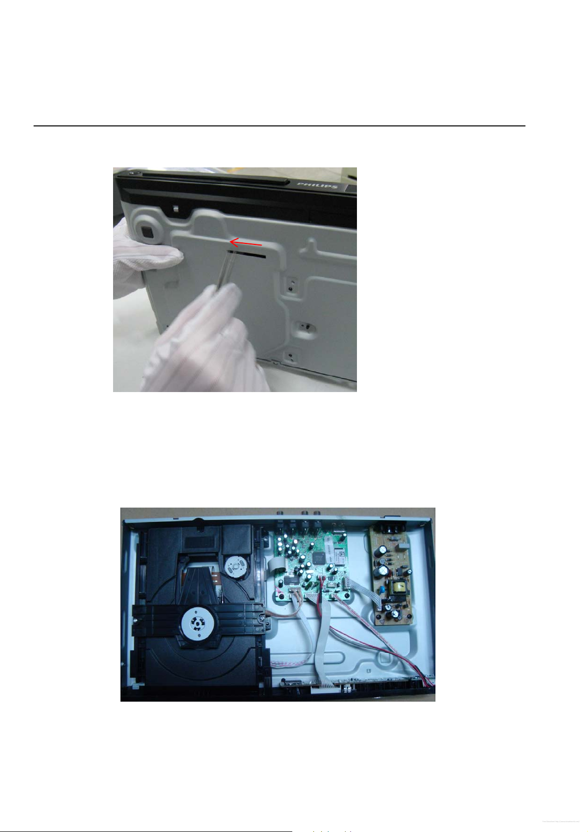
Step2: If it is necessary to dismantle Loader or Front Panel, the Front door should be removed first. (Figure 2)
Note: Make sure to operate gently otherwise the guider would be damaged.
e kindly note that dismantle the front door
Pleas
assembly carefully to avoid damage tray and the front door.
Figure 2
2-2
Free Datasheet http://www.datasheet4u.net/
XP2
XP4
XP3
XP5
XP7
XP6
XP1
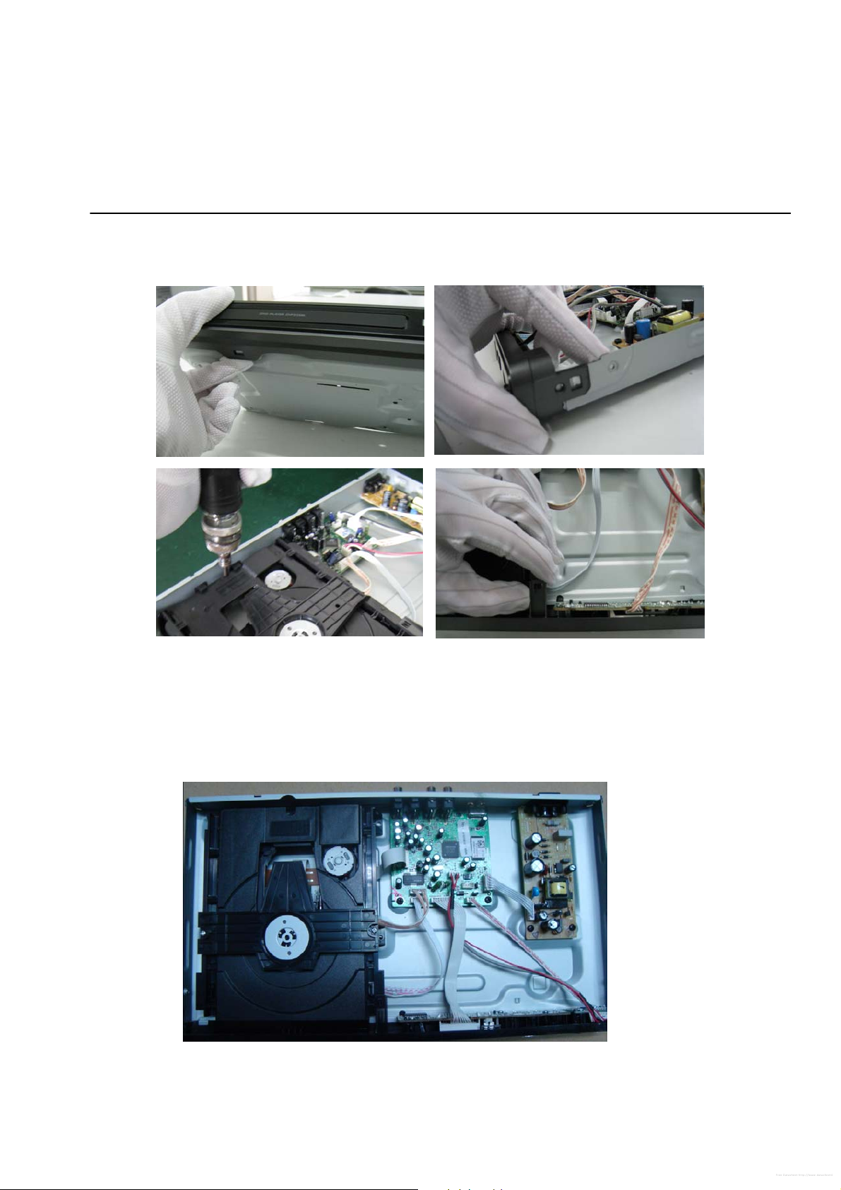
Mechanical and Dismantling Instructions
Dismantling Instruction
St
ep3: If the tray can’t open in normal way, you can make it through the instruction as below (Figure 3).
Note: Make sure to operate gently otherwise the guider would be damaged.
Detailed information please refer to the model set.
Step4: Dismantling Front Panel, disconnect the connectors (XP5, XP6,XP7), need release 4 snaps of Front Panel & 2 snaps
of bottom cabinet , then gently pull the Panel out from the set. (Figure 4 - Figure 6)
Figure 3
Figure 4
2-3
Free Datasheet http://www.datasheet4u.net/
Mechanical and Dismantling Instructions
Dismantling Instruction
Step5: Dismantling Loader, disconnect the 3 connectors (XP2, XP3, XP4) aiming in the below figure, and remove 1 screw that
connects the loader and the bottom cabinet. (Figure 5)
Detailed information please refer to the model set.
Figure
St
ep6: Dismantling Main Board, first disconnect the connector (XP1), and then remove 5 screws. (Figure 6)
Step7: Remove the 4 screws on Power Board to dismantle the Power Board. (Figure 6)
5
Figure 6

3-1
Free Datasheet http://www.datasheet4u.net/
Software upgrade
Preparation to upgrade software
1) Start the CD Burning software and create a new CD project (Data Disc) with the following setting:
Label: DVP3XXX (No need the label name)
File Name: DVPXXXX_XX.BIN
Power on the set and open the tray, then press <option> to check the File Name.
Note: It is required capital letter for the File System name
2) Burn the data onto a blank CDR
A. Procedure for software upgrade:
1) Power on the set and insert the prepared Upgrade CDR.
2) The set will starts reading disc & response with the following display TV screen:
Upgrade file detected
VXX(SW VER )
<X> <O>
3) Press <OK> button to confirm, then screen will display :
Upgrade file detected
UPGRADING…
Do not power off…
4) The upgraded tray will automatically o pen when files coping complete, then take out the disc.
5) About 1 minute later, the trace will automatically close when upgra ding complete.
B. Read out the software versions to confirm upgrading
1) Power on the set and press <Setup> button on the remote control.
2) Press <Up><Next>< Up >< Up ><OK> button.
The software version and other information are display on the TV screen as follows:
Model DVP3XXX_ XX
File Name DVPXXXX_XX.BIN
Version XX.XX.XX.XX
8203RX XX.XX.XX.XX
RISC XXXXXX-XXX-XXX
Servo XXXXX-XXX-XXXX
Region Code X
Caution: The set must not be power off during
upgrading, Otherwise the Main board will be
damaged entirely.
Free Datasheet http://www.datasheet4u.net/
4-1
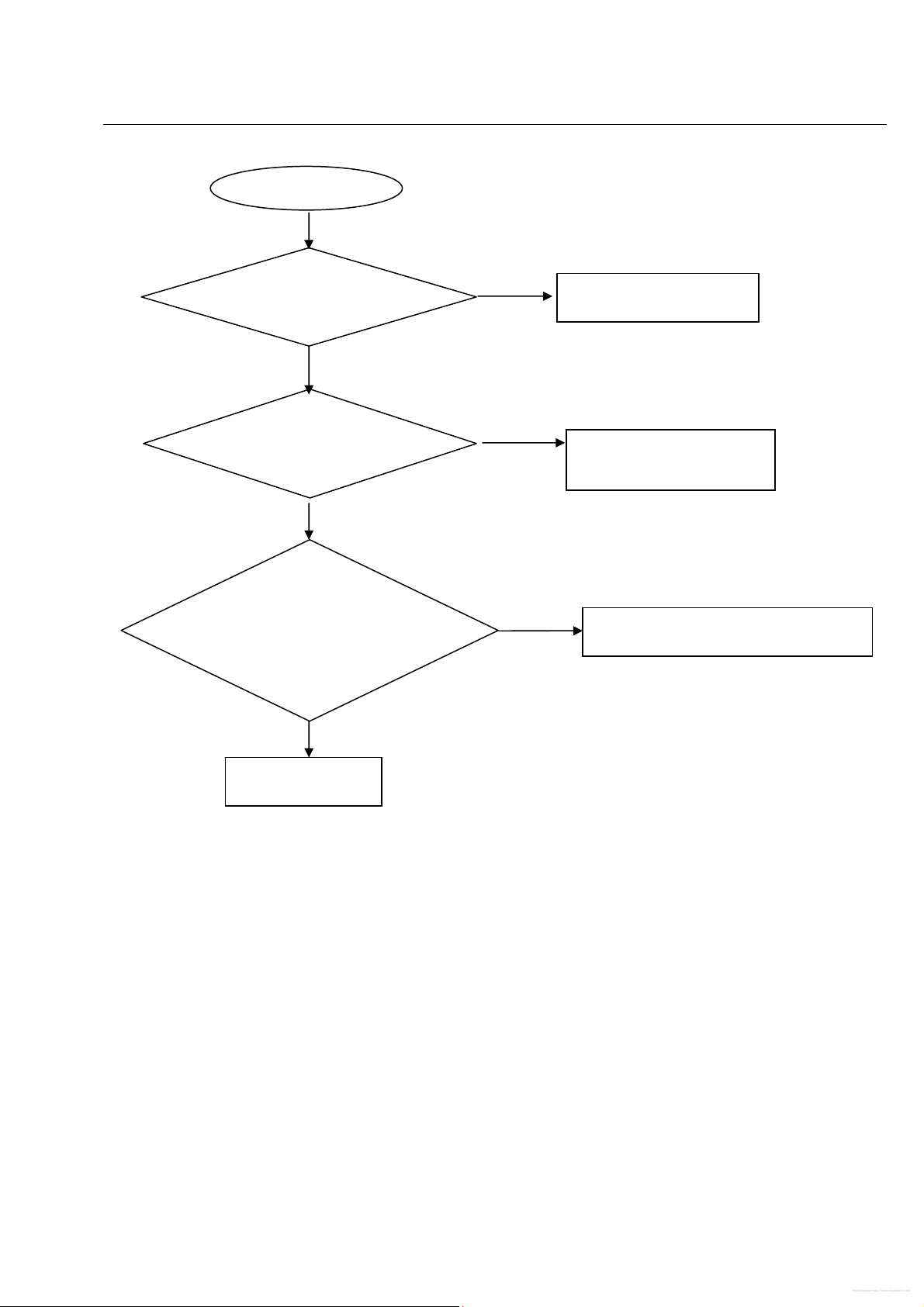
Spindle motor does not move
Trouble shooting chart
Motor no move
Go
Check the FFC connection
between 24PIN and the loader.
Correct connection
No
Yes
Check whether “M5V”
(+5V) voltage is normal.
No
Check the M5V power supply
Yes
1.Whether the current of R25 is Less than
65mA for CD; R26 is Less than 60mA for
DVD),
2.Whether peripheral components between
U1 and xp5 are eroded or badly soldered.
No
Check/Replace the loader,or the bad part.
Yes
Check/ Replace U1