

Philips DVP-3560-K Service Manual
DVP3560K
DVP3560K/55
Service Manual
TABLE OF CONTENTS
. Technical Specifications…………....………………………..............1-2
. Safety Instruction, Warning & Notes….……………………....….....1-3
. DFU Instruction..............................................................................2-1
. Mechanical and Dismantling Instructions…………........................3-1
. Software Upgrades and Region Code Change.............................
. Trouble Shooting Chart………………………………………………
. Wiring Diagram………………………………………..………..….….6-1
. Electrical Diagrams and Print-layouts..….…………………....….…7-1
. Set Mechanical Exploded view & Part list.…………………..….….8-1
. Revision List..................................................................................9-1
©Copyright 2010 Philips Consumer Electronics B.V. Eindhoven, The Netherlands
All rights reserved. No part of this publication may be reproduced, stored in aretrieval system or
transmitted, in any form or by any means, electronic, mechanical, photocopying, or otherwise
without the prior permission of Philips.
Page
.
4-1
.
5-1
CLASS 1
LASER PRODUCT
Published by SL - 952 BU AVM Printed in The Netherlands Subject to modification
Version 1.0
GB
3141 785 34640
PHILIPS

(VSHFLÀFDFLRQHV
Nota
/DVHVSHFLÀFDFLRQHV\HOGLVHxRTXHGDQVXMHWRVD
PRGLÀFDFLRQHVVLQSUHYLRDYLVR
USB
Compatibilidad: USB (2.0) de alta velocidad
Clases: UMS (clase de almacenamiento masivo
USB)
Video
Sistema de señal: PAL/NTSC
Salida de video compuesto: 1 Vpp ~ 75 ohmios
Salida de video por componentes:
0,7 Vpp ~ 75 ohmios
Salida HDMI: 480i, 480p, 576i, 576p, 720p,
1080i, 1080p
Audio
Salida estéreo analógica
5HODFLyQVHxDOUXLGRN+]!G%
(ponderado A)
5DQJRGLQiPLFRN+]!G%3RQGHUDGR$
,QWHUIHUHQFLDN+]!G%
'LVWRUVLyQUXLGRN+]!G%
MPEG MP3: MPEG Audio L3
Salida digital
Coaxial
Salida HDMI
1-2
Unidad principal
Dimensiones (An x Al x Pr): 360 x 39 x 209 (mm)
Peso neto: 1,4 kg aproximadamente
Energía
&ODVLÀFDFLyQGHODIXHQWHGHDOLPHQWDFLyQ
110 - 240 V, 50/60 HZ
Consumo de energía: <10 W
Consumo de energía en el modo de espera:
< 0,45 W
Accesorios incluidos
Control remoto y baterías
Cable HDMI
Cables de audio/video
Cable de suministro eléctrico de CA
Adaptador de cable de alimentación
Manual del usuario
(VSHFLÀFDFLyQGHOiVHU
Tipo: láser semiconductor InGaAIP (DVD),
AIGaAs (CD)
Longitud de onda: 658 nm (DVD), 790 nm (CD)
Potencia de salida: 7,0 mW (DVD), 10,0 mW
(VCD/CD)
Divergencia de haz: 60 grados

1-3
Safety instruction, Warning & Notes
Safety instruction
1. General safety
Safety regulations require that during a repair:
. Connect the unit to the mains via an isolation transformer.
. Replace safety components indicated by the symbol
only by components identical to the original ones. Any
other component substitution (other than original type)
may increase risk of fire or electrical shock hazard.
Safety regulations require that after a repair, you must
return the unit in its original condition. Pay, in particular,
attention to the following points:
. Route the wires/cables correctly, and fix them with the
mounted cable clamps.
. Check the insulation of the mains lead for external
damage.
. Check the electrical DC resistance between the mains
plug and the secondary side:
1) Unplug the mains cord, and connect a wire between
the two pins of the mains plug.
2) Set the mains switch the “on” position (keep the
mains cord unplug).
3) Measure the resistance value between the mains
plug and the front panel, controls, and chassis
bottom.
4) Repair or correct unit when the resistance
measurement is less than 1M
5) Verify this, before you return the unit to the
customer/user (ref. UL-standard no. 1492).
6) Switch the unit “off”, and remove the wire between
the two pins of the mains plug.
¡
.
2.Laser safety
This unit employs a laser. Only qualified service personnel
,
may remove the cover, or attempt to service this device
(due to possible eye injury).
Laser device unit
Type : Semiconductor laser GaAlAs
Wavelength : 650nm (DVD)
: 780nm (VCD/CD)
Output power : 7mW (DVD)
: 10mW (DVD /CD)
Beam divergence: 60 degree
Note: Use of controls or adjustments or performance of
procedure other than those specified herein, may result in
hazardous radiation exposure. Avoid direct exposure to
beam.

Warning
1-4
1.General
. All ICs and many other semiconductors are susceptible to
electrostatic discharges (ESD). Careless handing during
repair can reduce life drastically. Make sure that, during
repair, you are at the same potential as the mass of the
set by a wristband with resistance. Keep components and
tools at this same potential. Available ESD protection
equipment:
1) Complete kit ESD3 (small tablemat, wristband,
connection box, extension cable and earth cable)
4822 310 10671.
2) Wristband tester 4822 344 13999.
. Be careful during measurements in the live voltage
section. The primary side of the power supply , including
the heat sink, carries live mains voltage when you
connect the player to the mains (even when the player is
“off”!). It is possible to touch copper tracks and/or
components in this unshielded primary area, when you
service the player. Service personnel must take
precautions to prevent touching this area or components
in this area. A “lighting stroke” and a stripe-marked
printing on the printed wiring board, indicate the primary
side of the power supply.
. Never replace modules, or components, while the unit is
“on”.
2. Laser
. The use of optical instruments with this product, will
increase eye hazard.
. Only qualified service personnel may remove the cover
or attempt to service this device, due to possible eye
injury.
. Repair handing should take place as much as possible
with a disc loaded inside the player.
. Text below is placed inside the unit, on the laser cover
shield:
CAUTION: VISIBLE AND INVISIBLE LASER
RADIATION WHEN OPEN, AVOID EXPOSURE
TO BEAM.
Notes: Manufactured under licence from Dolby
Laboratories. The double-D symbol is trademarks of Dolby
Laboratories, Inc. All rights reserved.

Notes
Lead-Free requirement for service
1-5
INDENTIFICATION:
Regardless of special logo (not always indicated)
One must treat all sets from 1.1.2005 onwards, according
next rules.
Important note
be treated in this way as long as you avoid mixing
solder-alloys (leaded/ lead-free). So best to always use
SAC305 and the higher temperatures belong to this.
Due to lead-free technology some rules have to be
respected by the workshop during a repair:
x Use only lead-free solder alloy Philips SAC305 with
order code 0622 149 00106. If lead-free solder-paste is
required, please contact the manufacturer of your
solder-equipment. In general use of solder-paste within
workshops should be avoided because paste is not easy
to store and to handle.
x Use only adequate solder tools applicable for lead-free
solder alloy. The solder tool must be able
o To reach at least a solder-temperature of 400°C,
o To stabilize the adjusted temperature at the
o To exchange solder-tips for different applications.
x Adjust your solder tool so that a temperature around
360°C
joint. Heating-time of the solder-joint should not exceed
~ 4 sec. Avoid temperatures above 400°C otherwise
wear-out of tips will rise drastically and flux-fluid will be
destroyed. To avoid wear-out of tips switch off un-used
equipment, or reduce heat.
x Mix of lead-free solder alloy / parts with leaded solder
alloy / parts is possible but PHILIPS recommends
strongly to avoid mixed
solder alloy types (leaded and lead-free). If one cannot
avoid, clean carefully the
solder-joint from old solder alloy and re-solder with new
solder alloy (SAC305).
: In fact also products a little older can also
solder-tip
– 380°C is reached and stabilized at the solder
x Use only original spare-parts listed in the
Service-Manuals. Not listed standard-material
(commodities) has to be purchased at external
companies.
x Special information for BGA-ICs:
- always use the 12nc-recognizable soldering
temperature profile of the specific BGA (for
de-soldering always use highest lead-free
temperature profile, in case of doubt)
- lead free BGA-ICs will be delivered in so-called
‘dry-packaging’ (sealed pack including a silica gel
pack) to protect the IC against moisture. After
opening, dependent of MSL-level seen on
indicator-label in the bag, the BGA-IC possibly
still has to be baked dry. This will be
communicated via AYS-website.
Do not re-use BGAs at all.
x For sets produced before 1.1.2005, containing
leaded soldering-tin and components, all needed
spare-parts will be available till the end of the
service-period. For repair of such sets nothing
changes.
x On our website:
www.atyourservice.ce.Philips.com
You find more information to:
BGA-de-/soldering (+ baking instructions)
Heating-profiles of BGAs and other ICs used in
Philips-sets
You will find this and more technical information
within the “magazine”, chapter “workshop news”.
For additional questions please contact your local
repair-helpdesk.
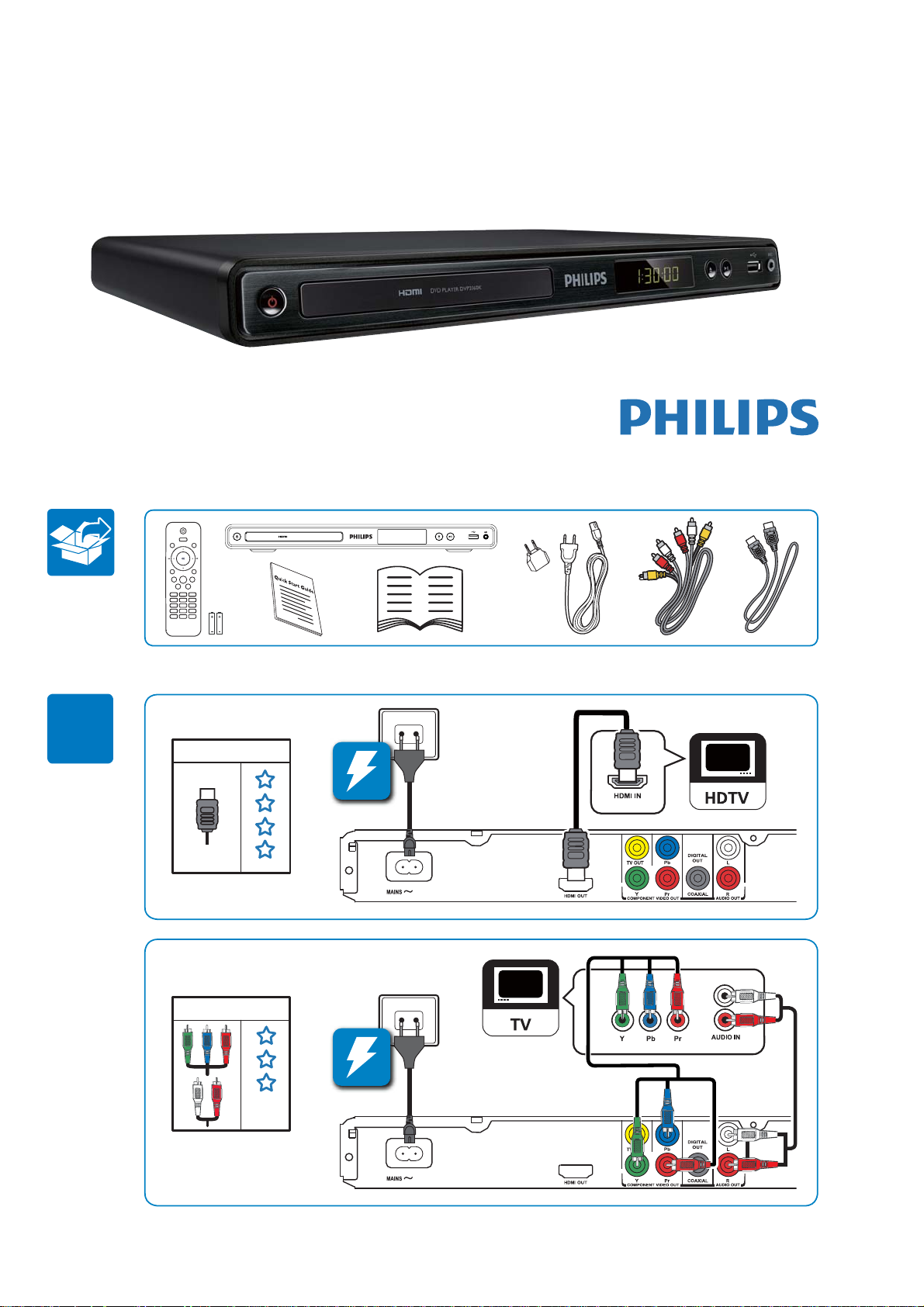
QSG for DVP3560K/55:
2-1
Register your product and get support at
www.philips.com/welcome
DVD PLAYER DVP3560K
DVP3560K
1
HDMI
HDMI OUT
Y Pb Pr & AUDIO OUT
DVD PLAYER DVP3560K
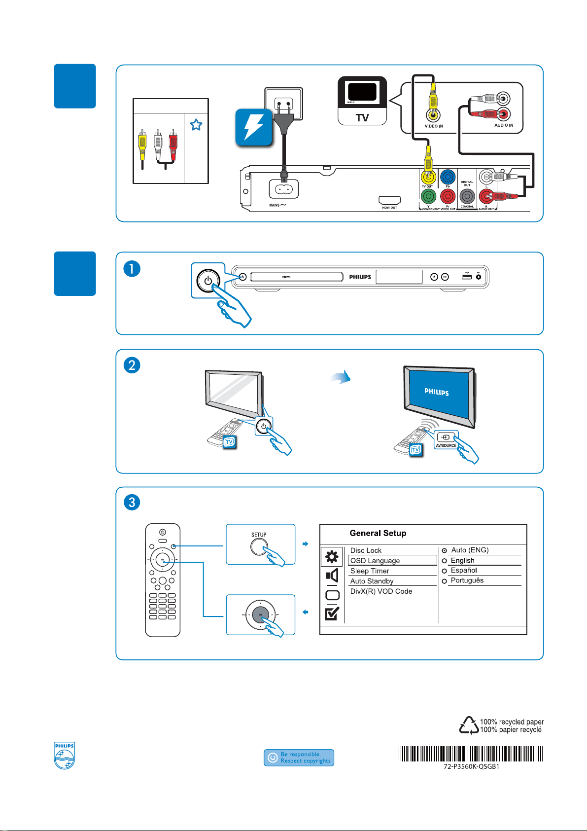
2-2
1
2
TV OUT & AUDIO OUT
2009 © Koninklijke Philips N.V.
All rights reserved.
DVP3560K_55_QSG_V1.0
2-3
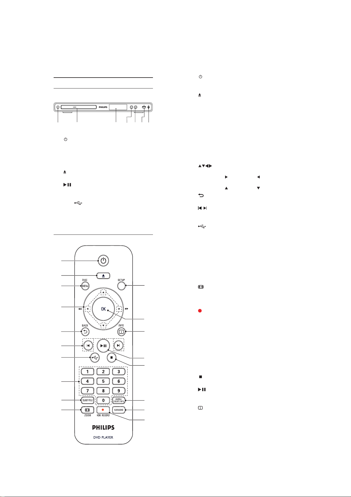
Descripción general del producto
Unidad principal
DVD PLAYER DVP3560K
ab cdefg
a (Modo de espera encendido)
b Compartimiento para el disco
c Panel de visualización
d
e
f Tom a
g MIC
Control remoto
a
b
c
d
e
f
g
h
i
j
Enciende el reproduc tor de DVD o pasa
al modo de espera.
(Abrir/Cerrar)
Abre o cierra la bandeja de discos.
(Play/Pause)
Inicia, hace una pausa o reanuda la
reproducción del disco.
(USB)
Conec ta una unidad USB Flash.
Conexión de micrófono.
r
q
p
o
n
m
l
k
a
b
c
d
e
f
g
h Botones numéricos
i SUBTITLE
j
k
l KARAOKE
m AUDIO/CREATE MP3
n
o
p
q OK
r SETUP
Enciende la unidad o pasa al modo de
espera.
Abre o cierra la bandeja de discos.
DISC MENU
Accede o sale del menú del disco.
Pasa al modo de disco.
Durante la reproducción de una
secuencia de diapositivas de fotos,
permite alternar entre el modo de
diver sión y el modo simple.
Para VCD y SVCD, activa o desactiva el
control de reproducción PBC (del inglés
Playback Control).
Navega a través de los menús.
Avanza (
rápidamente.
Avanza (
BACK
Regresa al menú de pantalla anterior.
/
Pasa al título, capítulo o pista anterior o
siguiente.
Pasa al modo de USB.
Selecciona la reproducción de un
elemento.
Selecciona el idioma de los subtítulos en
un disco.
Permite acceder al menú de copia y
eliminación de archivos de audio USB.
ZOOM
Ajusta el formato de la imagen a la
pantalla del televisor.
Acerca o aleja la imagen.
KOK RECORD
Graba la voz y la música durante el
NDUDRNHHQXQGLVSRVLWLYRÁDVK86%
$FFHGHRVDOHGHOPHQ~GHFRQÀJXUDFLyQ
de karaoke.
Selecciona un canal o idioma de audio en
un disco.
Permite acceder al menú de creación de
archivos MP3.
Detiene la reproducción.
Inicia, hace una pausa o reanuda la
reproducción del disco.
INFO
En discos: permite acceder a las opciones
de reproducción o muestra el estado
actual del disco.
Para diapositivas, muestra una vista en
miniatura de archivos de fotos.
3HUPLWHFRQÀUPDUODHQWUDGDRVHOHFFLyQ
$FFHGHRVDOHGHOPHQ~GHFRQÀJXUDFLyQ
) o retrocede ( )
) o retrocede ( ) lentamente.
3-1
Mechanical and Dismantling Instructions
Dismantling Instruction
The following guidelines show how to dismantle the player.
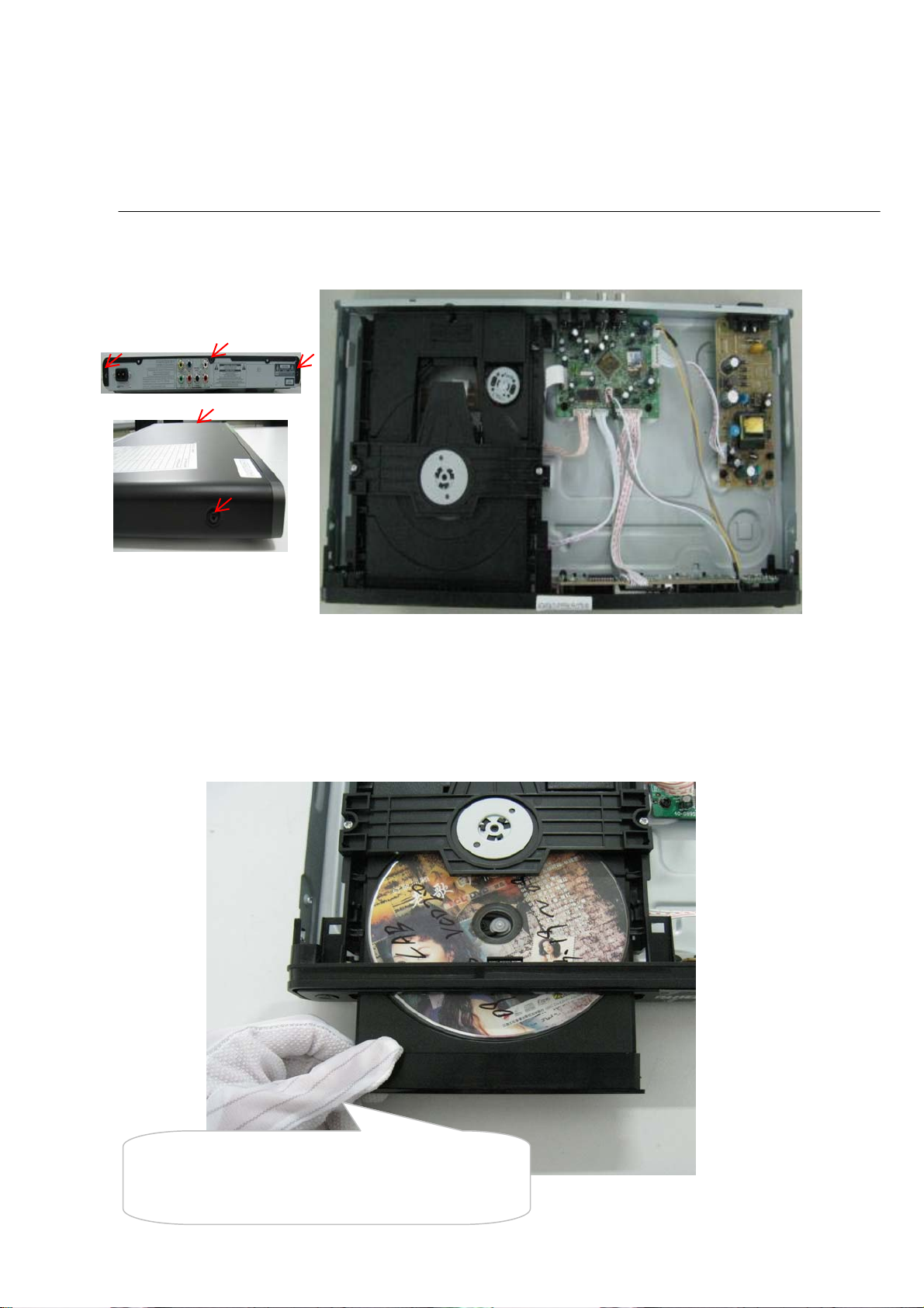
Step1: Remove 5 screws around the Top Cover, and then remove the Top Cover (Figure 1).
Detailed information please refer to the model set.
Figure 1
Step2: If it is necessary to dismantle Loader or Front Panel, the Front door should be removed first. (Figure 2)
Note: Make sure to operate gently otherwise the guider would be damaged.
Please kindly note that dismantle the front door
assembly carefully to avoid damage tray and the front door.
Figure 2
3-2
XP2
XP3
XP80
XP4
XP7
XP1
XP476
Mechanical and Dismantling Instructions
Dismantling Instruction
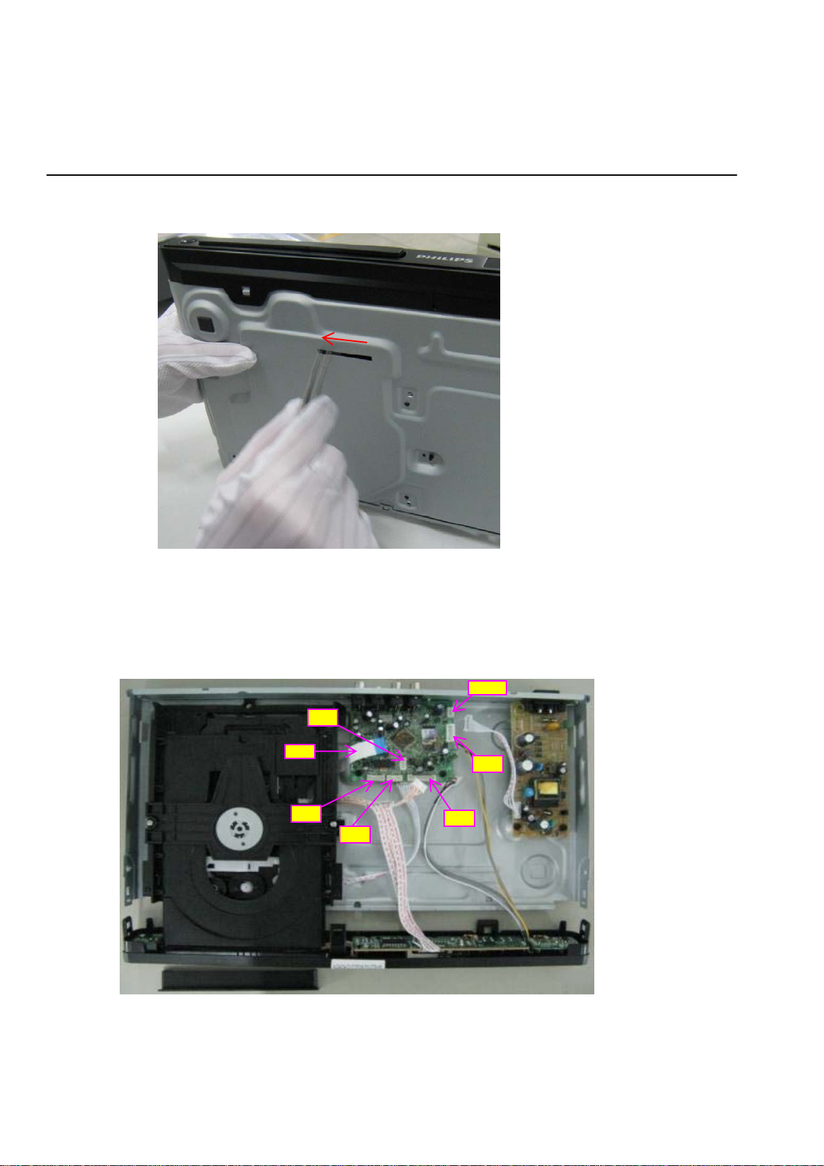
Step3: If the tray can’t open in normal way, you can make it through the instruction as below (Figure 3).
Note: Make sure to operate gently otherwise the guider would be damaged.
Detailed information please refer to the model set.
Step4: Dismantling Front Panel, disconnect the connectors (XP80 , XP7, XP476), need release 3 snaps of Front Panel & 2 snaps
of bottom cabinet , then gently pull the Panel out from the set. (Figure 4 - Figure 6)
Figure 3
Figure 4
3-3
Mechanical and Dismantling Instructions
Dismantling Instruction
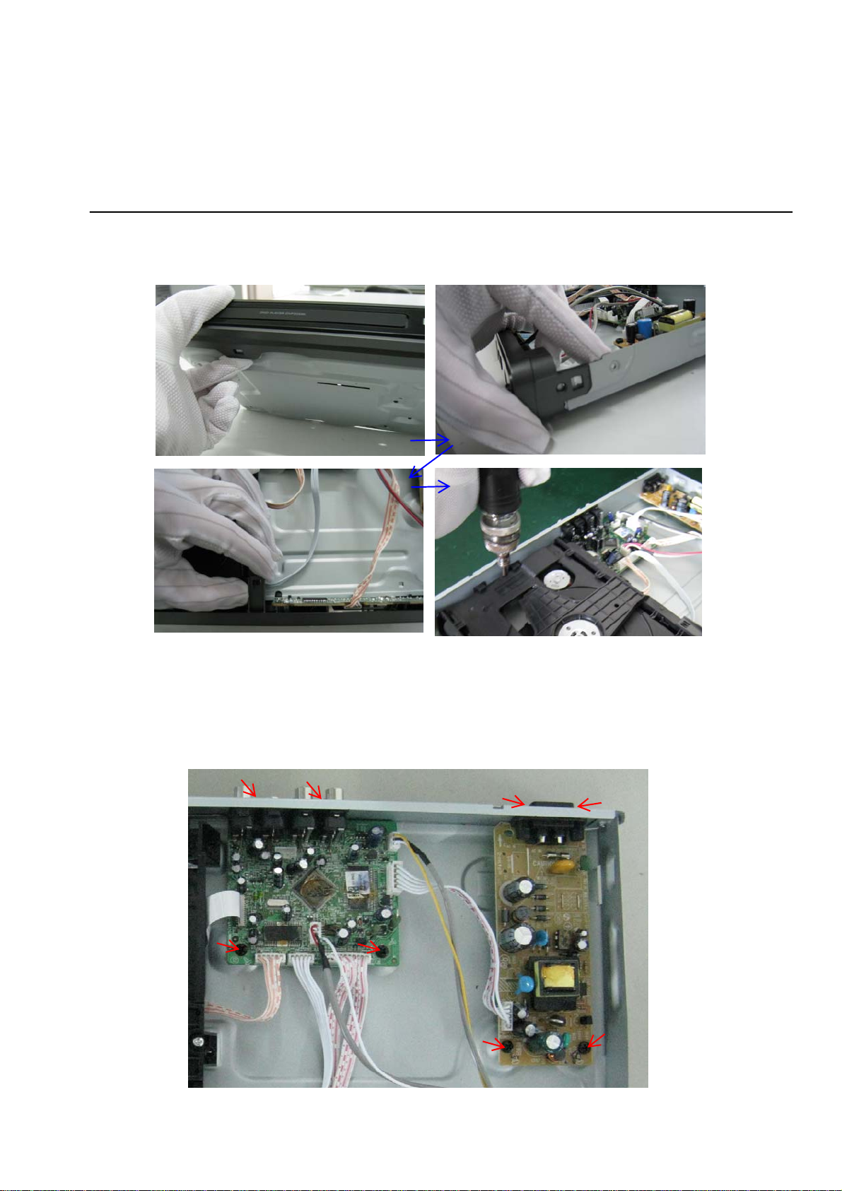
Step5: Dismantling Loader, disconnect the 3 connectors (XP2, XP3, XP4) aiming in the below figure, and remove 1 screw that
connects the loader and the bottom cabinet. (Figure 5)
Detailed information please refer to the model set.
Figure 5
Step6: Dismantling Main Board, first disconnect the connector (XP1), and then remove 4 screws. (Figure 6)
Step7: Remove the 4 screws on Power Board to dismantle the Power Board. (Figure 6)
Figure 6

4-1
Softeware upgrade and region code change
Preparation to upgrade software
1) Power on the set and open the tray, then press "5""5"
on remote control to check the SW File Name.
2) Start the CD Burning software and create a new CD
project (Data Disc) with the following setting:
Label: DVP3XXX(K) (No need the label name)
SW File Name:
Note: It is required to keep the SW file name accord.
3) Burn the data onto a blank CDR
A. Procedure for software upgrade:
A) Upgrade software via CDR:
1) Power on the set and insert the prepared Upgrade CDR.
2) The set will starts reading disc & response with the
following display TV screen:
Upgrade file detected
Upgrade ?
Press PLAY to start
3) Press "PLAY" button to confirm, then screen will display:
Upgrade file detected
Do not power off
File Copying
4) The upgraded tray will automatically open when file
copying completed, then take out the disc.
5) About 1 minute later, the trace will automatically close
when upgrading completed.
DVPXXXX(K)_XX.bin
Upgrade file detected
Do not power off
Upgrading
B. Read out the software versions to confirm upgrading
1) Power on the set and press "Setup" button on the
remote control.
2) Press "1""3""7""9" button or press down cursor
on remote control to select "Preferences" and press
right & down cursor to select "Version Info".
The software version and other informations will be
displayed on the TV screen as follows:
Version XX.XX.XX.XX (Main version)
Sub-Ver XX.XX.XX.XX (version of applicaton software)
8032 XX.XX.XX.XX
Servo XX.XX.XX.XX (software version of
RISC XX.XX.XX.XX
DSP XX.XX.XX.XX
Region Code X
Servo)
Caution: The set must not be power off during
upgrading, Otherwise the Main board will be
damaged entirely.
B) Upgrade software via USB Flash Drive:
1) Create the correct software file onto the USB flash drive.
2) Power on the set and keep no disc, then insert it to the
USB jack of the front panel.
3) When the DVD player switchs to the USB state automatically,
pls follow the instructions on the TV screen to confrim the
upgrade operation.
Region Code Change
1) Power on the set and open the tray door;
2) Press the "Setup" button on the remote control, then the
setup interface will be displayed on the TV screen;
3) Move the down cursor on remote control to select "Preferences"
and press "1""3""8""9""3""1" on the remote control;
4) Then move the up or down cursor to select the region code.
Note: Restart after above steps.
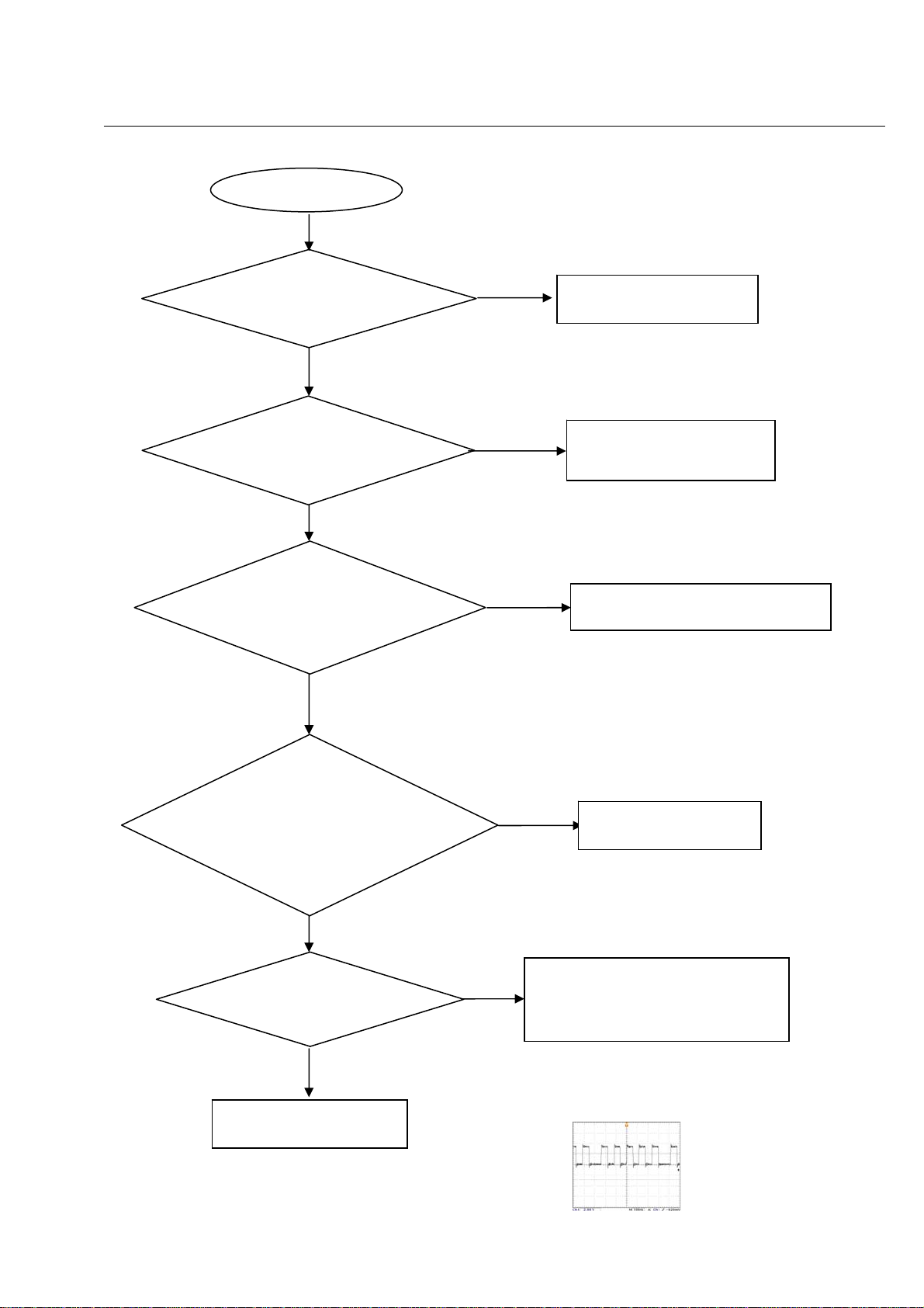
Spindle motor does not move
Motor no move
Go
5-1
Trouble shooting chart
Check the FFC connection
between 24P and the loader.
Yes
Check whether “MO_VCC”
(+5V)
voltage is normal.
Yes
Check whether laser voltage
(1.9V for CD & 2.4V for DVD)
on L9 and L10
Yes
No
No
No
Correct connection
Check the MO_VCC power
supply
Check/Replace Q5,Q6,Q7,Q8.
1.Whether voltage on pin 15of U20
varies between 0 and 3.3V (3.3V for
CD and 0V for DVD),
2.Whether peripheral components
are eroded or badly soldered.
Yes
Check opu focus
Yes
Check/Replace the loader
No
No
Check/ Replace U20.
1. Check U20 pin17 FOCUS_PWM signals
2.If there are F+, F-, T+ and T- signals output
from U2.
FOCUS_PWN waveform
 Loading...