

Page 1
• Your TV’s Audio/Video In channel may be called AUX or AUXILIARY IN, AUDIO/VIDEO or A/V IN, EXT1
or External In, etc., and may be near channel zero (0). See your TV manual for details. Your TV’s
remote may have a button or switch that selects different Video In channels.Or, go to your lowest TV
channel and change channels down until you see the blue Philips DVD background picture or the
Initial Setup Screen on the TV (when the DVD Recorder is on).
• If your TV has a single Antenna In (or RF IN or 75 ohm input) jack, see the DVD Recorder’s owner’s
manual for connection instructions.
1
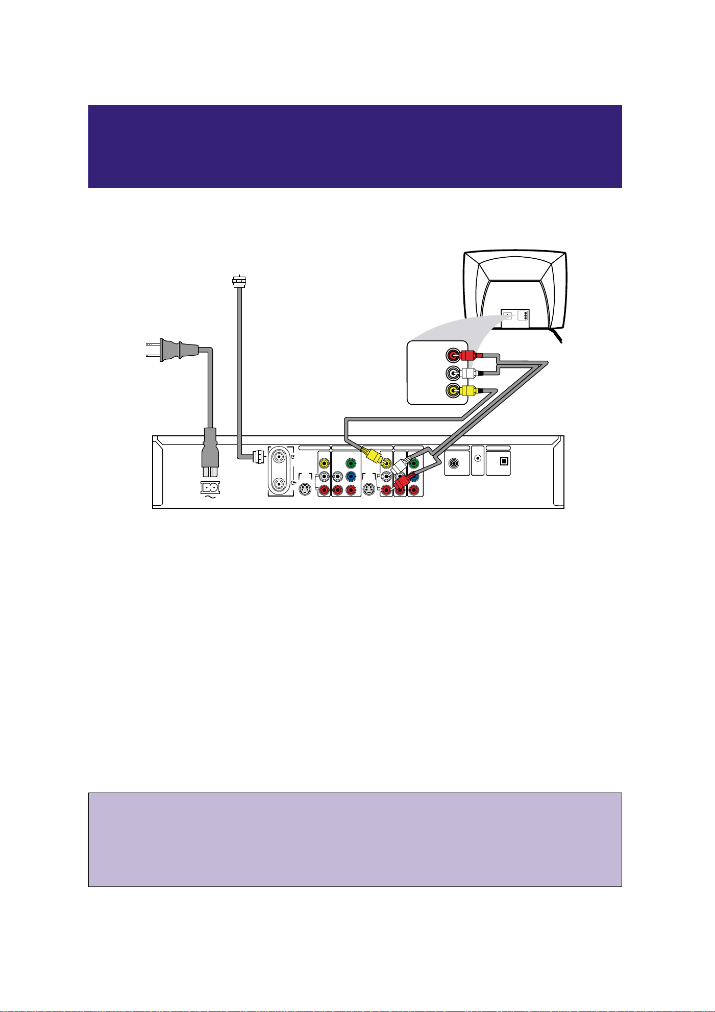
Connect your Antenna or Cable TV signal to the ANTENNA jack on the rear of the DVD Recorder.
2
Connect the supplied video cable (which has yellow markings) to the yellow VIDEO (CVBS) OUT 2 jack
of the DVD Recorder and to the VIDEO IN jack on your TV.
3
Connect the supplied audio cable(s) (red/white markings) to the red/white, right/left AUDIO OUT 2
jacks on the Recorder and to the TV’s right/left AUDIO IN jacks. Match the cable colors to the jack colors.
4
Because you are not using a Cable Box, you should remove the Demo Pin from the G-LINK jack on the rear of
the DVD Recorder. Details are on page 7 of this Quick-Use Guide.
5
Connect the supplied power cord to the MAINS (AC Power) jack on the rear of the DVD Recorder.
Connect the power cords of the Recorder and the TV to a power outlet.
The first time you connect the Recorder’s power cord, available features will scroll across the display panel on the
front of the Recorder.This will stop when you turn on the Recorder’s power.
6
Press STANDBY yyto turn on the DVD Recorder. Turn on the TV and set it to the correct Audio/Video
In channel.
You should see the DVD Recorder’s Initial Setup menu on the TV the first time you turn on the
Recorder. Go to pages 4-5 of this Quick-Use Guide to set up the Recorder for the first time.
Quick-Use Guide
Follow these simple instructions to get your new DVD Recorder working quickly.
For other connections and features, refer to the owner’s manual.
1
S-VIDEO
(Y/C)
ANTENNA
TV
S-VIDEO
(Y/C)
VIDEO
(CVBS)
VIDEO
(CVBS)
COMPONENT
VIDEO
AUDIO
COMPONENT
VIDEO
AUDIO
Y
P
B
P
R
Y
P
B
P
R
IN - EXT 2 IN - EXT 1
OUT 2 OUT 1
480p/480
i IN - EXT 1
COAX OUT
G-LINK
DIGITAL AUDIO OUT
OPTICAL OUT
MAINS
AUDIO
L
R
AUDIO
L
R
Audio and Video cables to the
DVD Recorder's red/white
AUDIO OUT 2 and
yellow VIDEO (CVBS)
OUT 2 jacks and to the TV's
AUDIO IN and VIDEO IN jacks
Power cord to the
DVD Recorder's
MAINS jack and
to a power outlet
LEFT AUDIO IN
RIGHT AUDIO IN
VIDEO IN
LEFT AUDIO IN
RIGHT AUDIO IN
VIDEO IN
Antenna or Cable TV signal
to the DVD Recorder's
ANTENNA jack
Connecting the DVD Recorder
(No Cable Box)
Page 2
1
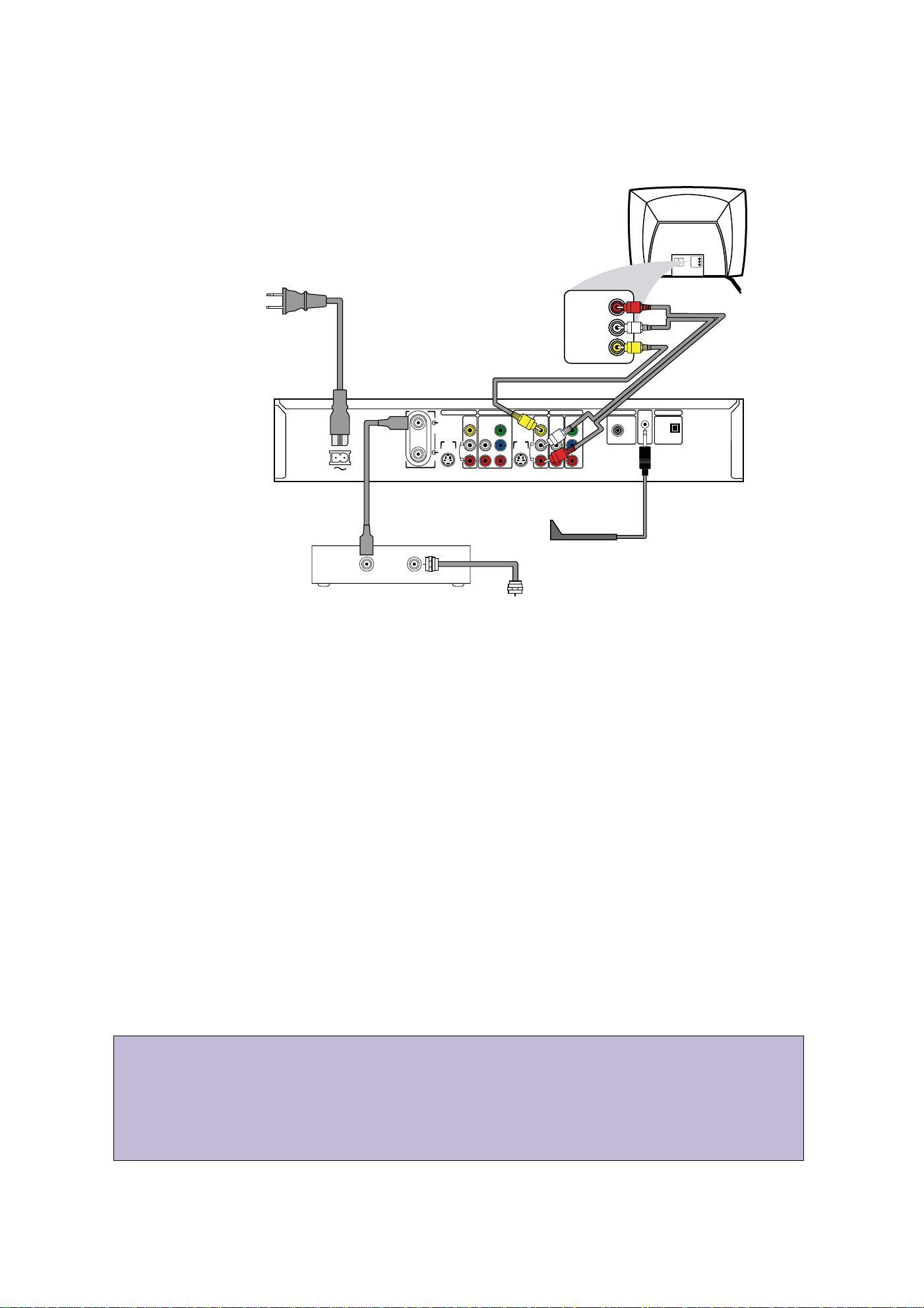
Connect the Cable TV signal to the IN jack on your Cable Box. The IN jack may be labelled differently. See the
Cable Box owner’s manual for details.
2
Connect an RF coaxial cable to the OUT jack of the Cable Box and to the ANTENNA jack on the rear
of the DVD Recorder. The OUT jack may be labelled RF OUT, TO TV, or ANTENNA OUT. See the Cable Box
owner’s manual for details.
3
Connect the supplied video cable (with yellow markings) to the yellow VIDEO (CVBS) OUT 2 jack of
the DVD Recorder and to the VIDEO IN jack on your TV.
4
Connect the supplied audio cable(s) (with red/white markings) to the red/white, right/left AUDIO OUT
2 jacks on the Recorder and to the TV’s right/left AUDIO IN jacks. Match the cable colors to the jack colors.
5
You will need the G-Link cable in order to use the GUIDE Plus+®System. Connect the supplied G-Link cable to
the G-LINK jack on the rear of the DVD Recorder. (Remove the Demo Pin first if it is still attached to the G-
LINK jack.) Place the sensor of the G-Link cable in front of the Cable Box so it faces the remote sensor of your Cable
Box. The G-Link cable’s sensor should be within one inch of the front of your Cable Box.
6
Connect the supplied power cord to the MAINS (AC Power) jack on the rear of the DVD Recorder.
Connect the power cords of the DVD Recorder, Cable Box, and TV to a power outlet.
The first time you connect the DVD Recorder’s power cord, the features of the Recorder will scroll across the display
panel on the front of the Recorder.This will stop when you turn on the DVD Recorder’s power.
7
Press STANDBY yyto turn on the DVD Recorder. Set the DVD Recorder to channel 3 or 4 (the output
channel of your Cable Box).Turn on the TV and set it to the correct Audio/Video In channel.
You should see the Initial Setup menu on the TV screen the first time you turn on the DVD Recorder.
Go to pages 4-5 of this Quick-Use Guide to set up the DVD Recorder for the first time.
Power cord to the
2
• Your TV’s Audio/Video In channel may be called AUX or AUXILIARY IN, AUDIO/VIDEO or A/V IN, EXT1
or External In, etc., and may be near channel zero (0). See your TV manual for details. Your TV’s
remote may have a button or switch that selects Video In channels. Or, go to your lowest TV channel
and change TV channels down until you see the blue Philips DVD background picture or the Initial
Setup Screen on the TV (when the DVD Recorder is on).
• If you have a Satellite Receiver, the hookup resembles that of a Cable Box. However, you cannot use
the GUIDE Plus+
®
System, so do not connect the G-Link cable.
Connecting the DVD Recorder with a Cable Box
DVD Recorder's
MAINS jack and
to a power outlet
RIGHT AUDIO IN
LEFT AUDIO IN
VIDEO IN
RF coaxial cable to the
OUT jack of the Cable Box
and to the DVD Recorder's
ANTENNA jack
MAINS
Audio and Video cables to the
DVD Recorder's red/white
AUDIO OUT 2 and
yellow VIDEO (CVBS) OUT 2
jacks and to the TV's
AUDIO and VIDEO IN jacks
IN - EXT 2 IN - EXT 1
VIDEO
AUDIO
(CVBS)
ANTENNA
S-VIDEO
(Y/C)
L
AUDIO
TV
R
OUT IN
RIGHT AUDIO IN
LEFT AUDIO IN
COMPONENT
VIDEO
Y
S-VIDEO
(Y/C)
P
B
P
R
OUT 2 OUT 1
480p/480
VIDEO
COMPONENT
AUDIO
(CVBS)
VIDEO
L
AUDIO
R
Y
P
P
To front of Cable Box
(not used with Satellite)
Cable TV signal to the
IN jack on the Cable Box
VIDEO IN
i IN - EXT 1
COAX OUT
B
R
G-LINK
DIGITAL AUDIO OUT
OPTICAL OUT
Page 3
3
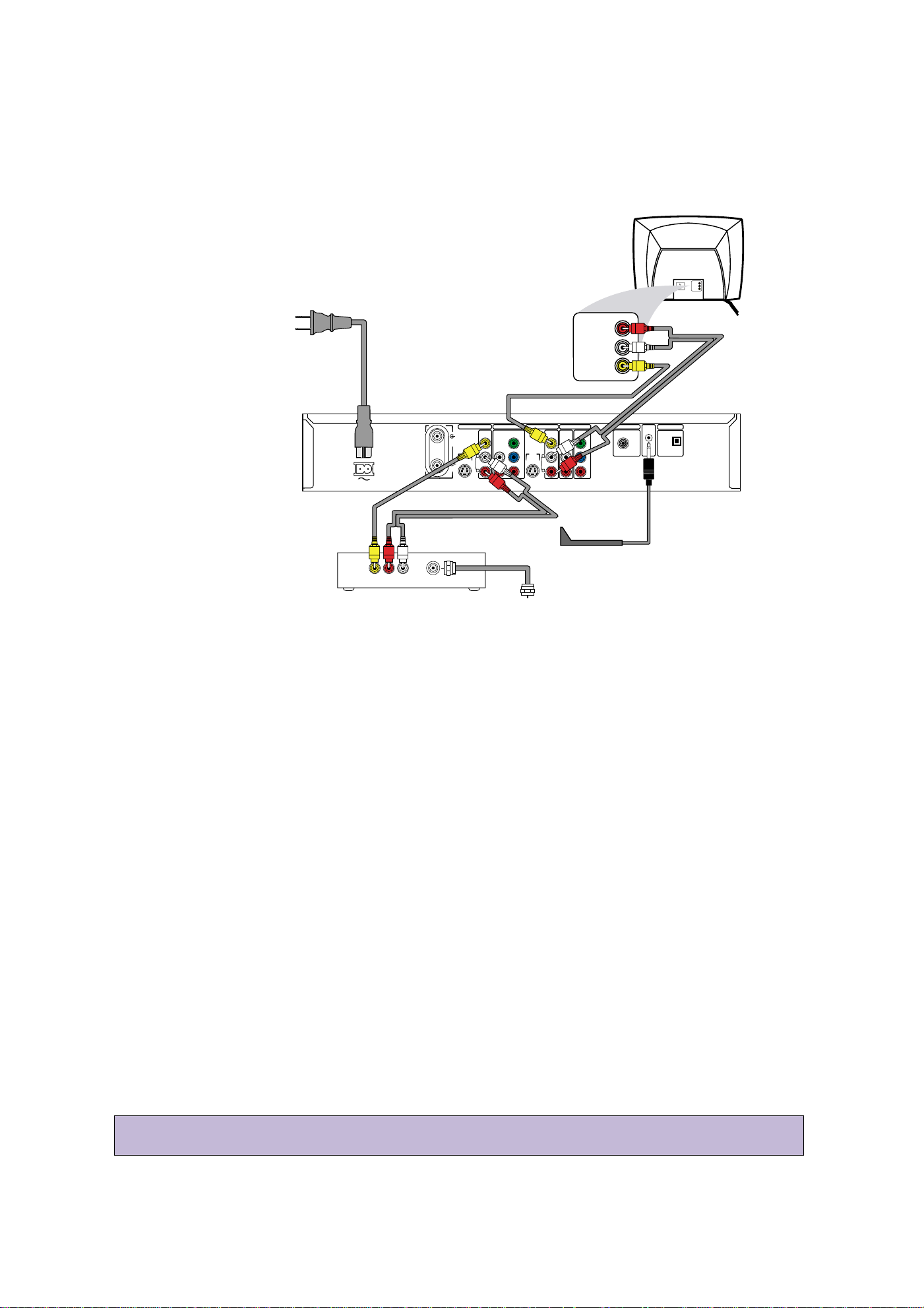
Your Cable Box may have Audio and Video Out jacks instead of a single ANTENNA OUT, TO TV, or RF OUT jack as
shown on page 2 of this Guide. If so, use the Audio and Video Out jacks to connect the Cable Box to your DVD Recorder.
1
Connect the Cable TV signal to the IN jack on your Cable Box.
2
Connect a composite video cable (usually yellow) to the VIDEO OUT jack on the Cable Box. Connect
the other end of the same video cable to the yellow VIDEO (CVBS) IN - EXT 2 jack on the Recorder.
3
Connect audio cables to the right/left AUDIO OUT jacks on the Cable Box. Connect the other ends of
the same audio cables to the Recorder’s red/white AUDIO (right/left) IN - EXT 2 jacks. Match the cable
colors to the jack colors.
4
Connect the supplied audio cables (red/white) to the red/white, right/left AUDIO OUT 2 jacks on the
DVD Recorder and to the right/left AUDIO IN jacks on your TV. Match the cable colors to the jack colors.
5
Connect the supplied video cable (yellow) to the DVD Recorder’s yellow VIDEO (CVBS) OUT 2 jack
and to the TV’s VIDEO IN jack.
6
You will need the G-Link cable in order to use the GUIDE Plus+®System. Connect the supplied G-Link cable to
the G-LINK jack on the rear of the DVD Recorder. (Remove the Demo Pin first if it is still attached to the G-
LINK jack.) Place the sensor of the G-Link cable in front of the Cable Box so it faces the remote sensor of your
Cable Box. The G-Link cable’s sensor should be within one inch of the front of your Cable Box.
7
Connect the supplied power cord to the MAINS (AC Power) jack on the rear of the DVD Recorder.
Connect the power cords of the Recorder,TV, and Cable Box to a power outlet. The first time you connect
the Recorder’s power cord, the features of the Recorder will scroll across its display panel.This will stop when you
turn on the DVD Recorder’s power.
8
Press STANDBY yyto turn on the DVD Recorder. Set the Recorder to EXT 2 (because those are the
jacks to which you connected the Cable Box). (To get to EXT 2, go to channel 1, then press 9CH- until you
reach the EXT 2 channel.) Turn on the TV; set it to the Audio/Video In channel.
You should see the Initial Setup menu on the TV the first time you turn on the DVD Recorder.
See pages 4-5 of this Quick-Use Guide to set up the DVD Recorder for the first time.
• If you have a Satellite Receiver, the hookup resembles that of a Cable Box. However, you cannot use
the GUIDE Plus+
®
System, so do not connect the G-Link cable.
Connecting the DVD Recorder with a Cable Box
(with Audio/Video Cables)
AUDIO
OUT
L
VIDEO
OUT
AUDIO
OUT
R
IN
S-VIDEO
(Y/C)
ANTENNA
TV
S-VIDEO
(Y/C)
VIDEO
(CVBS)
VIDEO
(CVBS)
COMPONENT
VIDEO
AUDIO
COMPONENT
VIDEO
AUDIO
Y
P
B
P
R
Y
P
B
P
R
IN - EXT 2 IN - EXT 1
OUT 2 OUT 1
480p/480
i IN - EXT 1
COAX OUT
G-LINK
DIGITAL AUDIO OUT
OPTICAL OUT
MAINS
AUDIO
L
R
AUDIO
L
R
Cable TV signal to the
IN jack on the Cable Box
To front of Cable Box
(not used with Satellite)
Audio and Video cables to the
DVD Recorder's red/white
AUDIO OUT 2 and
yellow VIDEO (CVBS) OUT2
jacks and to the TV's
AUDIO and VIDEO IN jacks
Power cord to the
DVD Recorder's
MAINS jack and
to a power outlet
LEFT AUDIO IN
RIGHT AUDIO IN
VIDEO IN
LEFT AUDIO IN
RIGHT AUDIO IN
VIDEO IN
Audio and Video cables from the
AUDIO and VIDEO OUT jacks
of the Cable Box to the
DVD Recorder's red/white
AUDIO IN -EXT 2 and yellow
VIDEO (CVBS) IN - EXT 2 jacks
Page 4

STANDBY
REC/OTR
TIMER REC MODE PLAY MODE TV/DVD
MONITOR
•TV
DIM RETURN T/C
DISC MANAGER FSS SELECT
SUBTITLE
STOP TV VOLUME
PAUSESLOW
PLAY
AUDIO ANGLE ZOOM
GUIDE/TV
MUTECLEAR
`
i
CH
-
CH
+
OKOK
SYSTEM
DISC
Ç
H Gk
M
ENU
Setting Up the DVD Recorder
Initial Setup
1
Before you can use your new DVD Recorder, you must
complete the Initial Setup.
Press STANDBY yyto turn on the Recorder. When you
turn on the Recorder for the first time, the first Initial Setup
menu (for Menu Language) will appear on the TV screen. “IS
TV ON? C03” will appear on the Recorder’s display panel.
This reminds you to turn on the TV and set it to the Video In
channel (Video In,Auxiliary, etc., depending on your hookup).
2
Use the 8CH+, 9CH-, and OK buttons on the remote
to select items during Initial Setup. Follow the onscreen instructions.
You will choose languages for different features, choose a TV
Shape, and set up TV channels. This will take a couple of minutes, but you must do it before you can use the Recorder.
You cannot turn off the Recorder or use any of the buttons
on the Recorder until you finish the Initial Setup.The only
way to quit is to disconnect the power cord.The Initial Setup
will appear again the next time you turn on the Recorder.The
menus will not go away until you finish the Initial Setup.
3
Press SYSTEM MENU to clear the screen when channels are set (when “Auto ch. search complete” appears).
Setting Up the GUIDE Plus+®System
4
When you finish the Initial Setup, GUIDE Plus+®System
information will appear on the TV. Press OK to continue.
5
When “Identifying Your Location” appears, press
8CH+ or 9CH- to highlight your country in yellow,
then press OK.
6
Next, press the Number buttons on the remote to
enter your postal zip code, then press OK.
7
The next message will ask whether you have Cable
TV service. Press 8CH+ or 9CH- to choose Yes or
No, then press OK. Choose Yes if you have a Cable TV
subscription. Choose No if you have only a regular antenna
connected to the DVD Recorder.
If you chose No, go to step 14.
If you chose Yes, go to step 8.
8
The next message will ask if you connected a Cable
Box to the DVD Recorder. Press 8CH+ or 9CH- to
choose Yes or No, then press OK.
If you chose No, go to step 14.
If you chose Yes, go to step 9.
~
Initial Setup
Menu Language
English
K
L
Español
Français
Press OK to continue
Installation
Auto Ch. Programming
Auto ch. search complete
024 Channels found
To exit press
SYSTEM MENU
4
1
2,4-8
3
6
Page 5

5
Setting Up a Cable Box
9
Press 8CH+ or 9CH- to select your Cable Box output channel, then press OK.
If you used an RF coaxial cable to connect the Cable Box to
the DVD Recorder (as shown on page 2 of this Guide),
choose channel 2, 3, or 4. If you used Audio and Video
cables as shown on page 3 of this Guide, choose EXT2. If
you connected the Cable Box to other jacks of the DVD
Recorder, select EXT 1, CAM 1, or CAM 2.
10
Directions for connecting the G-Link cable will appear on
the TV screen. If you have not connected the G-Link
cable yet, do so now. Press OK when the G-Link cable is
connected and you are ready to continue. More connection
details are on pages 2-3 of this Guide.
11
A list of Cable Box brands will appear. Press 8CH+ or
9CH- to select your Cable Box brand, then press
OK. If your brand is not listed, select “Not Listed.”
12
You will be advised to turn on the Cable Box and set it
to channel 2. After doing this, press OK to continue.
13
The DVD Recorder will start testing codes, which will allow
the G-Link cable to change the Cable Box to channel 9. A
message will ask you to confirm whether the Cable
Box has changed to channel 9. Press 8CH+ to select
Yes if the Cable Box has changed to channel 9, then
press OK.
If the Cable Box does not change to channel 9, check all
connections.Then, press 8CH+ or 9CH- to select “Test
this code again,” then press OK. Or, press 8CH+ or 9CHto choose No, then press OK. The DVD Recorder will try
a different code.
Repeat this process as necessary until the Cable Box
changes to channel 9. Several codes may have to be tested
before the correct one is found.
Finalizing Setup
14
The GUIDE Plus+®System settings will appear (“Confirming
Your Settings”). If the settings are correct, press
8CH+ to choose “Yes, end setup,” then press OK.
If the settings are incorrect, press 9CH- to choose “No,
repeat setup process,” then press OK.You will go through
the setup screens again. Change any incorrect information.
15
Helpful information about the GUIDE Plus+®System will
appear. Press OK to continue.
16
Another message confirming completion of setup will
appear. You will be prompted to press OK to activate
“Watch TV.” Press OK.You are finished!
Within a few seconds, the DVD Recorder will turn itself off,
then on again.
17
Press STANDBY yyto turn off the DVD Recorder.
The GUIDE Plus+
®
System programming informa-
tion will be available in about 24 hours. When the
Recorder is off, channels will change on your Cable Box.
This is normal, as the unit is searching for GUIDE Plus+
®
System information. For best results, turn off the DVD
Recorder overnight so it can receive the GUIDE Plus+
®
System programming information. Leave the Cable Box
turned on.
STANDBY
REC/OTR
TIMER REC MODE PLAY MODE TV/DVD
MONITOR
•TV
DIM RETURN T/C
DISC MANAGER FSS SELECT
SUBTITLE
STOP TV VOLUME
PAUSESLOW
PLAY
AUDIO ANGLE ZOOM
GUIDE/TV
MUTECLEAR
`
i
CH
-
CH
+
OKOK
SYSTEM
DISC
Ç
H Gk
MENU
17
12
13
9-16
CABLE
BOX
CABLE
BOX
CABLE
BOX
CABLE
BOX
• You must connect the G-Link cable in order
to make programmed recordings with a
Cable Box. Otherwise, the DVD Recorder
cannot change channels at the Cable Box.
The wrong channel may record if you do
not use the G-Link cable.
• Remember, you cannot use the GUIDE
Plus+®System if you connected the DVD
Recorder to a Satellite Receiver.
Page 6

Playing a Disc
1
Press STANDBY yyto turn on the DVD Recorder.
2
Turn on your TV. Set it to the correct Audio/Video In
channel.
3
Press OPEN/CLOSE A on the front of the DVD Recorder
to open the disc tray. Put a Disc in the tray, with the label
facing up and the shiny side facing down. Press
OPEN/CLOSE A again to close the tray.
4
Play may start automatically. If not, use 8CH+, 9CH-,
;, :, and OK on the remote to select items in a Disc
menu. Or, press PLAY : to start play.
(Some DVD Disc menus are accessible only if you press the
DISC MENU button on the remote during playback.)
5
To stop play at any time, press STOP C.
STANDBY
REC/OTR
TIMER REC MODE PLAY MODE TV/DVD
MONITOR
•TV
DIM RETURN T/C
DISC MANAGER FSS SELECT
SUBTITLE
STOP TV VOLUME
PAUSESLOW
PLAY
AUDIO ANGLE ZOOM
GUIDE/TV
MUTECLEAR
`
i
CH
-
CH
+
OKOK
SYSTEM
DISC
Ç
H Gk
MENU
GUIDE
OPEN/CLOSE
U
P
L
E
F
T
R
I
G
H
T
D
O
W
N
Recording a TV Program
To quickly record a TV program, follow these steps. See the
owner’s manual for recording details.
1
Press OPEN/CLOSE A on the front of the DVD Recorder
to open the disc tray. Insert a recordable DVD+RW or
DVD+R, then press OPEN/CLOSE A again to close the
disc tray. Place the Disc in the tray with the label facing up
and the shiny side facing down.The DVD+RW or DVD+R
should have one of the following logos.
2
Press 9CH- to select an empty Title Box/Index
Picture in the Index Picture Screen of a DVD+RW.
“Empty title” will appear to the right of the empty Index
Picture/Title Box. On a DVD+R, the DVD Recorder records
only at the end of the Disc.
3
Press MONITOR to see TV channels at the Recorder.
4
Press 8CH+, 9CH-, or the Number buttons to select
the channel you wish to record.
5
Press REC/OTR a to start recording. Red lights will sur-
round the disc tray and the UP/DOWN/LEFT/RIGHT buttons
on the front of the DVD Recorder during recording.
6
Press STOP C to stop recording. The Index Picture
Screen will reappear after a few seconds.
6
3
2,4
6
4
5
1
5
3
1
4
5
STANDBY
REC/OTR
TIMER REC MODE PLAY MODE TV/DVD
MONITOR
•TV
DIM RETURN T/C
DISC MANAGER FSS SELECT
SUBTITLE
STOP TV VOLUME
PAUSESLOW
PLAY
AUDIO ANGLE ZOOM
GUIDE/TV
`
i
CH
-
CH
+
OKOK
SYSTEM
DISC
Ç
H Gk
MENU
Red Recording lights
OPEN/CLOSE
P
U
GUIDE
R
I
G
T
F
H
E
T
L
D
N
O
W
DVDR 80
OPEN
Page 7

7
GUIDE Plus+®System Demonstration
When you first receive the DVD Recorder, a Demo Pin is inserted
in the G-LINK jack on the rear of the DVD Recorder.When this
pin is in place, the automatic demonstration of the GUIDE Plus+
®
System will run continuously.
Remove the Demo Pin to stop the demonstration. Grasp the tag
near the metal pin and pull the pin out of the G-LINK jack.The
demonstration will stop.
You must remove the Demo Pin before you can connect the GLink cable to the G-LINK jack.This will be necessary if you are
using a Cable Box with the DVD Recorder.
S-VIDEO
(Y/C)
VIDEO
(CVBS)
COMPONENT
VIDEO
AUDIO
VIDEO
Y
P
B
P
R
Y
P
B
P
R
OUT 2 OUT 1
480p/480
i IN - EXT 1
COAX OUT
G-LINK
DIGITAL AUDIO OUT
OPTICAL OUT
AUDIO
L
R
D
E
M
O
P
IN
T
h
is
D
e
m
o
P
in
a
c
tiv
a
te
s
a
n
a
u
to
m
a
tic
G
U
ID
E
P
lu
s
+
d
e
m
o
.
R
E
T
A
IL
E
R
S
D
o
n
o
t re
m
o
v
e
th
is
D
e
m
o
P
in
.
R
e
m
o
v
a
l w
ill d
is
a
b
le
th
e
a
u
to
-
m
a
tic
d
e
m
o
.
C
O
N
S
U
M
E
R
S
R
e
m
o
v
e
th
is
D
e
m
o
P
in
a
n
d
in
s
e
rt th
e
IR
e
x
te
n
d
e
r h
e
re
b
e
fo
re
u
s
in
g
th
is
T
V
.
W
A
R
N
IN
G
D
is
p
o
s
e
o
f p
ro
p
e
rly
.
K
E
E
P
A
W
A
Y
F
R
O
M
C
H
IL
D
R
E
N
GUIDE Plus+®System
Your DVD Recorder has the GUIDE Plus+®System, which lists TV
programs available in your area. Use it to select or record TV programs. Complete details are in the accompanying owner’s manual.
1
Press GUIDE/TV to see the GUIDE Plus+® System
screen. The TV channel you were viewing will appear in the
Video Window in the top left corner of the screen. (To
remove the GUIDE Plus+®System screen, press CLEAR or
press GUIDE/TV again.)
2
Press 8CH+ or 9CH- to select a TV program. The
selected show will appear in the Video Window. Press OK to
view the selected program and remove the GUIDE Plus+
®
System screen.
(You can add or delete TV channels to customize the channel
list for your area. See the owner’s manual for details.)
3
Or, in the top line of the GUIDE Plus+®System screen, you
can access different features. Press 8CH+ to access the
features, then press ; or : to choose:
LISTINGS: TV programs and their descriptions
SORT: See TV shows by category (Movies, Sports, etc.)
PROMOTIONS: Advertisements for special TV programs
SETUP: Change the settings of the GUIDE Plus+®System
MESSAGES: Messages about the GUIDE Plus+®System,
including an identification of your software version.This may
be useful if you need assistance or service.
SCHEDULE: Lists planned recordings or Favorite programs
4
Use the Blue AUDIOYYbutton or the Green ANGLE
button on the remote to activate GUIDE Plus+
®
System features that are marked with a Green or Blue circle.
Or, use the i button on the remote to see more information about a TV show or feature.
PBS
HSN
The 700 Club
Real TV
Last
Channel
FOX
abc
CBS
Maggi Sweet
Paid Program...
Instructional T...
Young & Restless
Port Charles
Martha Stewart
All My Children
Paid Program
Days of Our L...
Instructional T...
Big Valley
Paid Program
Paid Program
12:30PM
1:00PM
TODAY
Promotional
Panel
Promotional
Panel
Martha Stewart
SCHEDULE
LISTINGS
SORT
12:35
i
FAVORITES
RECORD
INFO
WCVB 5
Current Time
Video Window
Watch the selected
TV program here
Promotional
Panels
Advertising or
information about
the GUIDE Plus+
®
System
GUIDE Plus+
®
System Features
Program List
TV programs available in your area at
the designated time
Arrows
More programming
information is available to the right
(for later times and
days) or to the left
(for earlier times)
STANDBY
REC/OTR
TIMER REC MODE PLAY MODE TV/DVD
MONITOR
•TV
DIM RETURN T/C
DISC MANAGER FSS SELECT
SUBTITLE
STOP TV VOLUME
PAUSESLOW
PLAY
AUDIO ANGLE ZOOM
GUIDE/TV
MUTECLEAR
`
i
CH
-
CH
+
OKOK
SYSTEM
DISC
Ç
H Gk
MENU
4
2-3
1
Page 8

Title description
Program name and details
Disc Pointer
Current Title number and
its position within the Disc
X
10:25 am
L
C10 07:56AM
00:01:24 . M6
Wed 06/18/2003
C06 11:20AM
B
0100:00:22 . M6
Sun 07/06/2003
C10 12:01AM
00:58:53 . M6
Sun 05/11/2003
K
2
¡
012
Index Picture/Title Box
Recording or space available for recording
Timer Information Box
Current time or time/date
of next timer recording
Tuner Information Box
Current TV channel or
video source (CAM1,
CAM2, etc.)
User
Preferences
Title/Track Chapter Audio
Language
Subtitle
Language
Angle
Zoom Sound
Mode
Frameby-frame
playback
Slow
motion
Fast
motion
Time
Search
W
Z
Y
d
H
E
a
X
Index Picture Screen
The Index Picture Screen appears when Disc play is stopped. It
shows the recordings of a DVD+R or DVD+RW and provides
access to editing features for the recordings. For complete details,
refer to the accompanying owner’s manual.
System Menu
Use the System Menu to set up features of the DVD Recorder or
Discs. Access the System Menu by pressing the SYSTEM MENU button on the remote.The symbols in the System Menu have these
meanings. For details, see the accompanying owner’s manual.
8
EL6559E001
Printed in Hungary
SUPER AUDIO CD
DVDs must be labelled for ALL REGIONS or REGION ONE
as shown below.Also make sure your Discs are labelled as
NTSC or PAL compatible. These logos and information should
appear on the Disc case or on the Disc.
Playable Discs
Discs with these logos will play on the DVD Recorder.
• When you record on a DVD+R with this
DVD Recorder, finalize the Disc at the
Recorder if you plan to play the Disc on
other DVD Players.
Recordable
ReWritable
 Loading...