

Philips DVDR-985 Service manual
Philips DVDR985
Technical Training Manual
Philips Service and Quality/Training
One Philips Drive
Knoxville, TN 37914-1810
P. O. Box 14810
PH: 865-521-4397
FAX: 865-521-4818
EMAIL: TECHNICAL.TRAINING@PHILIPS.COM
Introduction
This Manual is intended for use by the Service
Technician. The first portion of this manual contains a basic description of disc based data playback and recording technologies. Self
Diagnostics are included to aid in troubleshooting. Technical Descriptions of the circuitry is followed by a Troubleshooting Section.
The DVDR985 is the forth in a line of DVD
recorders. The DVDR1500 was the first.
Recordings can be made from broadcast transmissions, and from other analog or digital
sources. The DVDRW format allows the user to
record and erase a disc many times. The recorded discs will play on most existing and future
DVD players. The DVDR985 has a connection
for DV or Digital camcorders via an I-Link or
Firewire connection. This connection technically
is called an IEEE 1394 connection. This machine
records on 4.7Gbyte DVD+R and DVD+RW
discs. This machine uses a real-time MPEG2
Variable Bit Rate, VBR, Video encoder. The
DVDR985 plays back DVD Video, Video CD,
Audio CD, CD-R, and CD-RW discs.
Its many features include: Favorite Scene
Selection for easy editing, Index Picture Screen
for instant overview of contents, Digital Time
Base Correcter, Digital Audio output (DTS, AC3, MPEG, PCM), TruSurround for 3D sound,
Zoom + Perfect Still. It is Widescreen, 16:9
compatible, and has a Universal Remote
Control, 20 disc resume, Disc Lock, and One
Touch Recording.
Virgin Mode
The DVDR985, when first hooked up, needs to
get information from the user about what language and what local broadcast system the
unit is going to operate with. Use the remote to
make those selections. The unit will not operate
until this process is completed. If you want the
recorder to start up in Virgin mode, unplug the
recorder. Plug the recorder in again while holding the STANDBY-ON button.
DVD Basics
Philips with nine other manufacturers chose a
format specification for DVDR and RW on March
16, 2001. This new format uses Real Time
recording. Its recording is compatible with DVDVideo, and DVD ROM. The data blocks use lossless linking. The physical layout matches very
closely that of DVD ROM. See Figure 1. It also
uses Direct Overwrite when a RW disc is used.
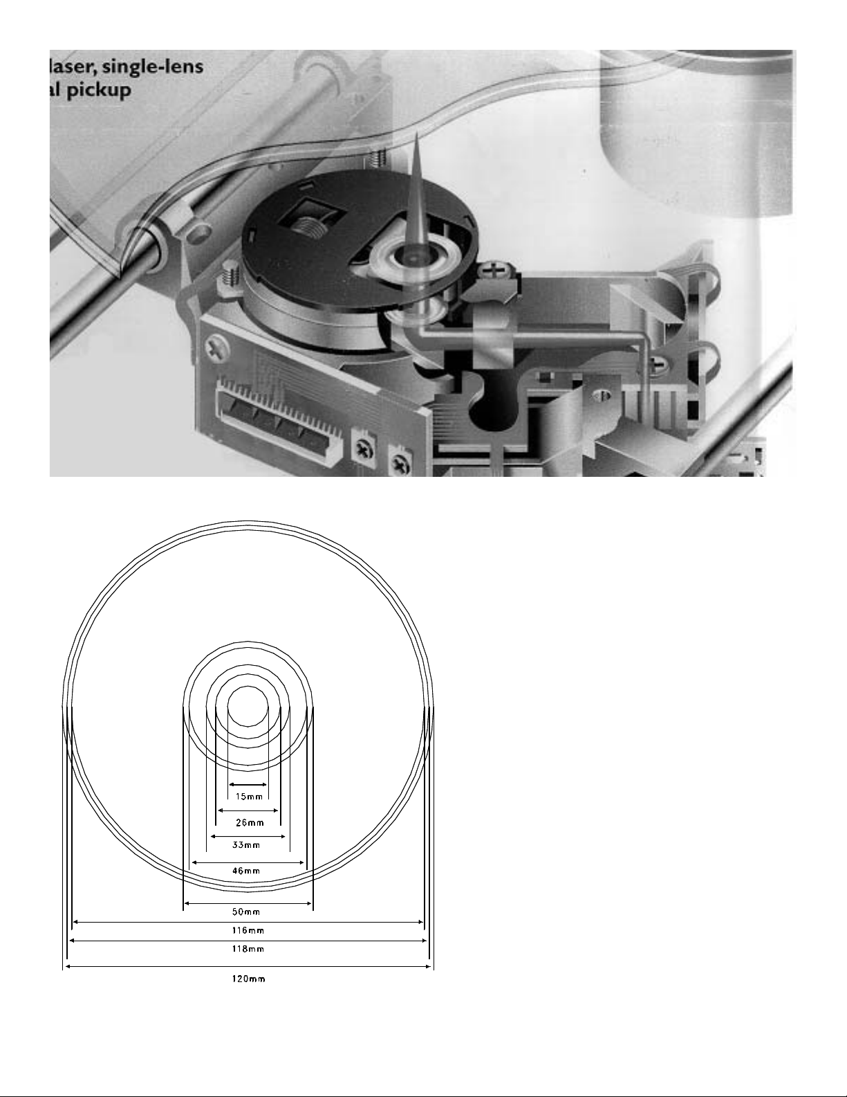
Laser Technology
CDs use a red laser created by a diode and lens
system often called a Light Pen. Refer to Figure
2. The narrow beam of light is focused onto the
reflective layer of a disc. At the instant that focus
is achieved, the disc is spun. The laser starts on
the innermost tracks of the CD and reads outward. At the beginning of the disc is the Table of
Contents. At the bottom of the Light Pen are
Monitoring Diodes. The Monitoring Diodes provide information about focus and tracking. Data
is retrieved from the disc in the form of pulses of
Figure 1 – DVD ROM Disc
1
light reflecting from the disc. The pulses are
created by Pits in the Reflective Layer of the
disc. The Pits reflect less light than the intact
surface of the Reflective Layer, called Lands.
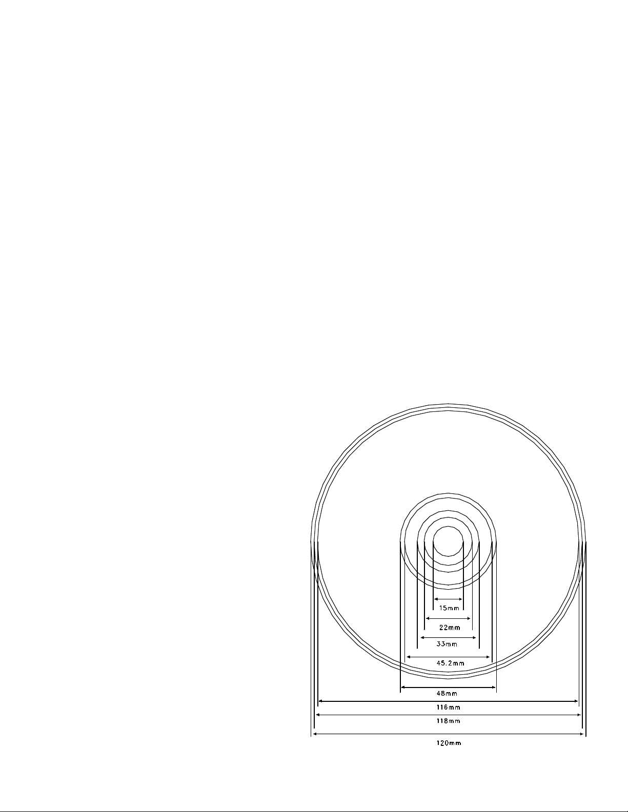
Disc Mechanical Layout
The DVD and CD share much of their technology. We will start with CDs and work our
way to the DVD. The CD is a plastic disc
120mm in diameter, with a thickness of
1.2mm. Refer to Figure 3. It has a silver col-
ored Reflective Layer. The maximum playing
time for a music recording on a Compact
Disc, CD, is 74 Min.
The CD is less vulnerable to damage than an
analog record. That does not mean it does
not have to be treated with care. Dirt and
heavy scratches can interfere with playability.
Figure 2 – CD Laser Operation
Figure 3 – Mechanical Layout of a CD.
2
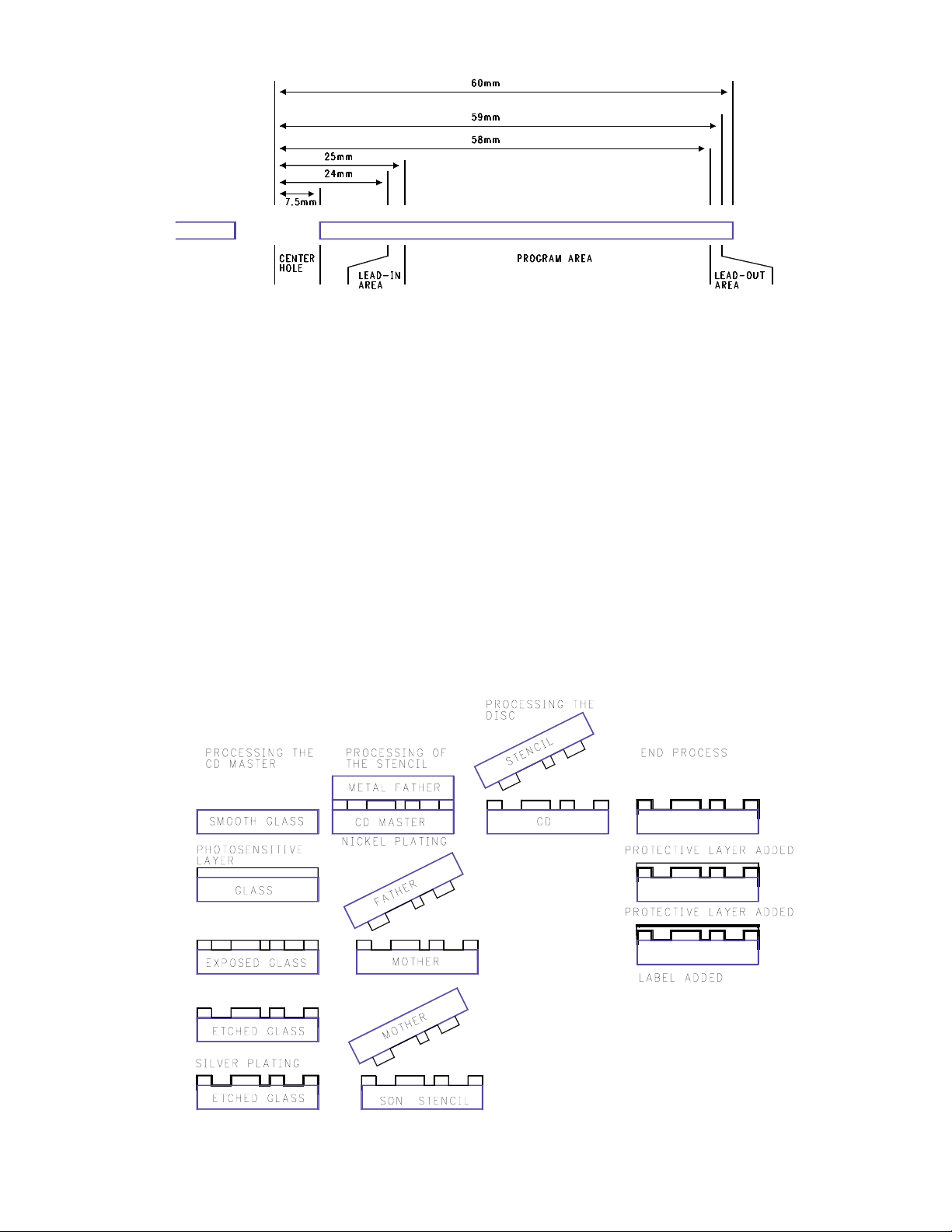
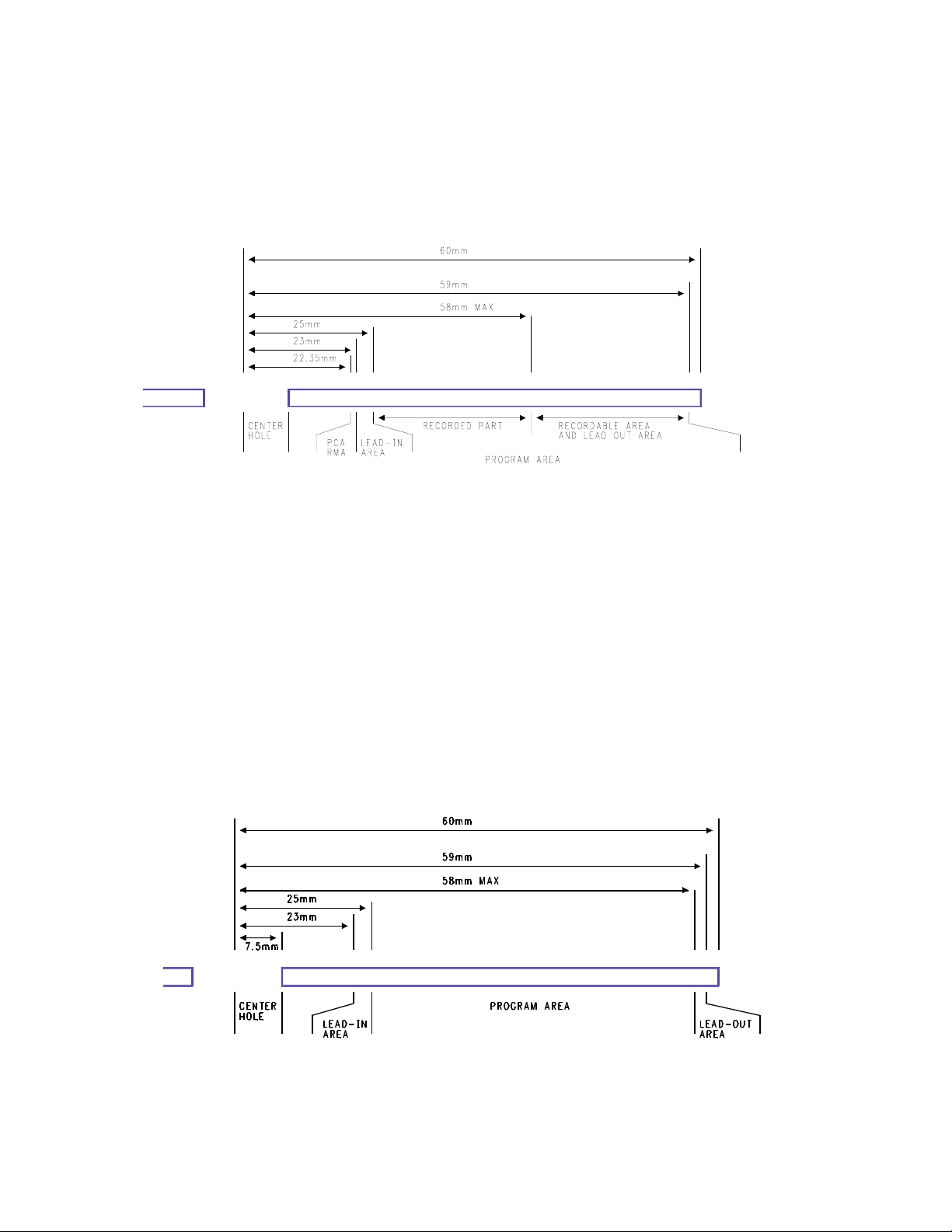
As shown in Figure 4, the CD is subdivided into
three parts: the Lead In Track, the Program
Area, and the Lead Out Area. These three sections together are considered the Information
Area. There is a hole in the center for holding
the disc. The disc is held between two equally
sized concentric rings. The rings have an inner
diameter of 29mm and an outer diameter of
31mm.
The Data on the disc is recorded on a spiral
shaped track with pits and lands. The reflective
side of the disc contains the tracks.
The production of a disc is a high tech process
explained in Figure 5. The process starts with
glass that is photo etched. The glass is silver
plated and is used as a form for a metal cast.
The metal cast is used to stamp a nickel Mother
Stencil. The Mother Stencil is used to stamp the
Son Stencil. Son Stencils are used to stamp the
foil of the discs. A protective layer and label are
added.
Read Process
The Servo circuit is responsible for focusing the
laser and moving the Light Pen to follow the spiraling tracks on the rotating disc. The digital High
Figure 4 - The Disc
Figure 5 - Creating a CD
3
Frequency information, HF, is demodulated and
stored in RAM. When the RAM is half full, the
data is fed out to the Digital to Analog
Converters. The speed of the rotating disc is
servo controlled to keep the RAM half full. The
analog signals are amplified and sent to the output connectors.
Record Once Technology
Disc Mechanical Layout
From an external point of view, a DVD is the
same as the CD. Recordable media creates the
need for three physical layouts. There are three
possible states of a disc: a blank disc, a partially
recorded disc, and a full or finalized disc. The
difference is in the way the Information Area is
divided. The Information Area of a blank disc
extends from 22.35 mm centered on the disc to
59 mm centered on the disc. Refer to Figure 6.
A partially recorded disc’s Information Area has
four sections: a PCA/RMA area, a Lead In Area,
a Recorded Program Area, and a Recordable
Program Area. See Figure 6 for the dimensions.
The PCA Area is the Power Calibration Area,
PCA. The RMAArea is the Recording
Management Area.
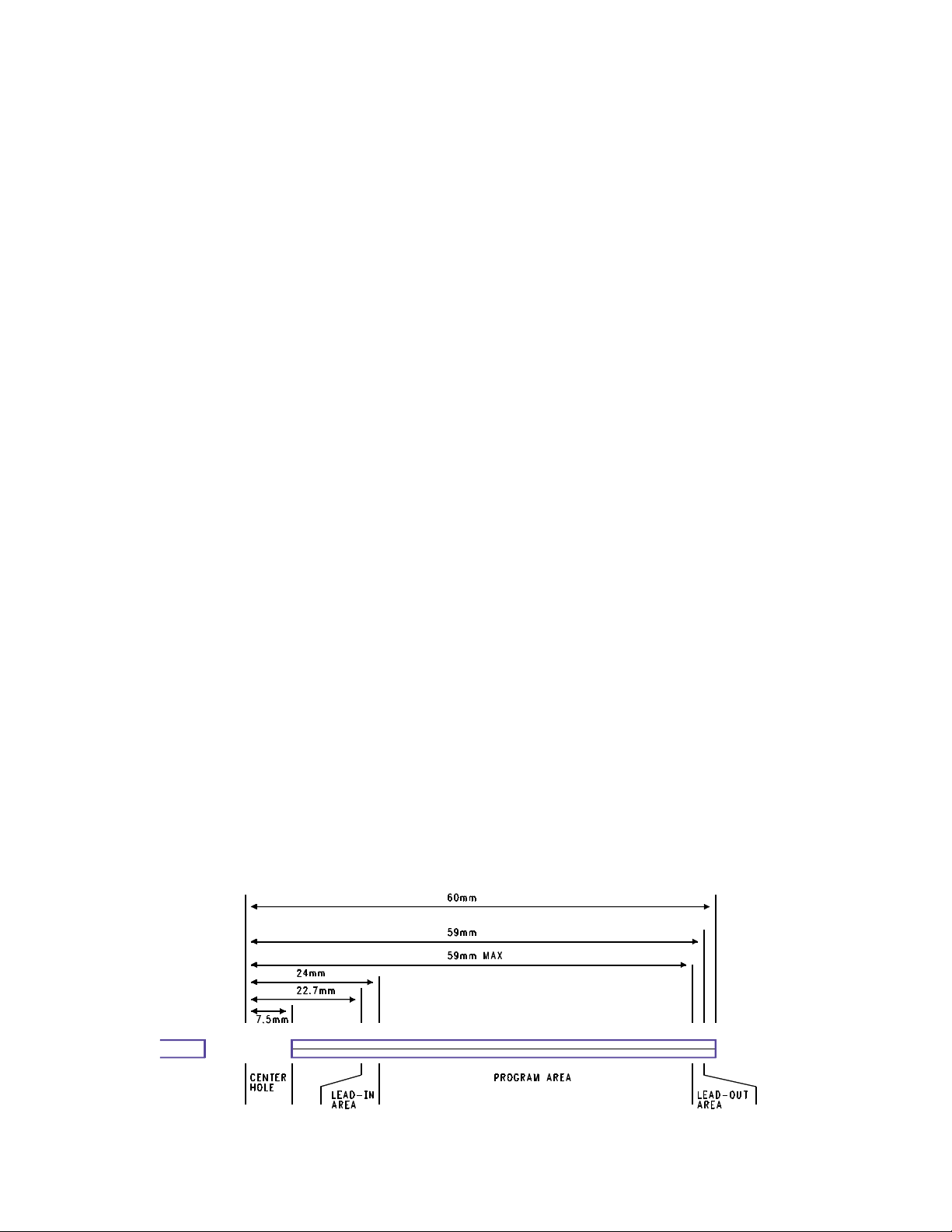
A fully recorded or finalized disc’s Information
Area has three sections: A lead in Area, the
Program Area, and the Lead Out Area. See
Figure 7 for the dimensions.
The disc’s recordable layer contains major differences from that of a stamped disc. The blank
disc has a Pre-groove stamped into the recordable layer of the disc. This is polycarbonant for
DVD+Rs and organic dye material for
DVD+RWs. This spiral Pre-groove is for the
Servo circuit to provide a mechanical reference
Figure 6 – A Partially Recorded Disc.
Figure 7 – Fully Recorded or Finalized Disc
4
during recording. The dye based RW recordable
layer provides a reflectivity of 40% light return
and 70% light return. 40 percent reflectivity represents Pits and the 70% represent the Lands.
Record Process
The record process shares most of its mechanical operation with that of the play process. The
main difference is how the Servo is locked to the
disc. The Servo follows the Pre-groove for Radial
Tracking and disc speed. The speed of the disc
is locked to a wobble signal that is part of the
spiral grove stamped into the disc.
The intensity of the laser beam is modulated
from playback intensity to write intensity. As the
disc reads the Pre-groove, the laser arrives at a
position where a Pit is to be formed. The laser
power increases from 4mW to 11mW. This raises
the temperature of the disc to 250 degrees
Celsius. The recordable layer melts, reducing its
volume. The polycarbonate flows into the space
vacated by the dye. The modulation from read
laser power to write laser power forms a pit and
land pattern effectively the same as a prerecorded disc.
Re-recordable Technology
Disc Mechanical Layout
Disc usage mechanically is identical to the
recordable media. The only difference is the
chemical make up of the recordable layer. The
recordable layer is made up of an alloy of silver,
indium, antimony and tellurium.
Re-Recording Process
The Re-Record process shares much of its operation with that of a CDR. The blank disc’s
Information Area is in a polycrystalline state.
During recording, the laser power is modulated
from 8mW to 14mW. 8mW is the playback laser
power and 14mW is the record laser power. The
polycrystalline state of the recordable surface
changes, or melts at 500-700 degrees C into an
amorphous state. The melted, amorphous areas
reflect light less than the crystalline areas, creating a pattern similar to the stamped CD. A major
difference of CDRWs from CDRs is the ability to
erase.
The Erase Process
To Erase a CDRW disc, the recordable layer
must be returned to its polycrystalline state. This
is done by heating up the temperature of the
recorded surface to 200 degrees C. This is less
than the melting point. This is done at X2 recording speed. The slower speed allows time for the
alloy to return to its proper state. This takes
approximately 37 min. Some software erases the
just the TOC on the disc and allows the disc to
be rewritten. This method is not as reliable
Over Writing Process
Overwriting combines the processes of erasing
and writing. When the disc and Light Pen are in
position to start writing the new data, the laser
power starts modulating in the same manner as
it does for normal recording with one difference.
During the time there is to be a land, the laser
power goes to the erase level rather than the
playback level.
Figure 8 – Mechanical Layout of a DVD
5
DVDs
All of the previously discussed technologies
apply to the DVD. Like CDs, DVDs are also
stamped into play only discs. In this discussion,
we will point out the differences between DVDs
and CDs. If you are new to disc based technology, you will want to start with the information preceding this discussion.
DVD Disc Mechanical Differences
Most DVDs are single sided, however, the DVD
specification allows for two readable layers, and
the disc can be double sided. We will start our
discussion with single sided, single layered
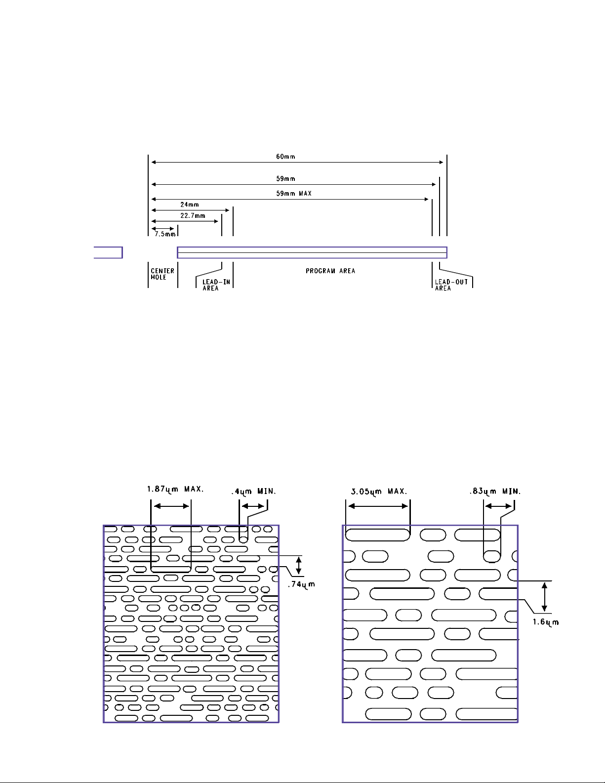
discs. A Digital Versatile Disc, DVD, looks very
similar to a CD. Refer to Figure 8. The Clamping
Area is larger, starting at 11 mm centered to 16.5
mm centered. The Lead In Area is smaller,
measuring 22.7 mm centered to 24 mm centered. The Information Area is limited to 116mm
centered.
Two of the big differences between DVDs and
CDs are the Pit and Land sizes, and the track
widths. Refer to Figure 9.
The Manufacturing process of a DVD is comparable to that of a CD. The main difference is the
thickness. The DVD can be a double sided product. Each side is .6mm. The two sides are glued
back to back, producing 1.2mm total thickness.
Figure 8 - DVD Mechanical Layout
Figure 9 – DVD and CD Pit Structure.
CD
DVD
6
Wobble
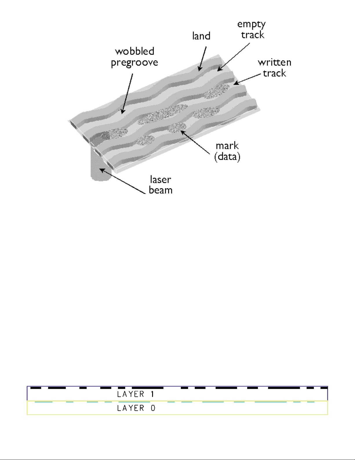
A Pre-groove is stamped on writable discs.
All recordable DVD media types feature a microscopic wobble groove embedded in the plastic
substrate. This wobble provides the recorder
with the timing information needed to place the
data accurately on the disc. During recording,
the drive's laser follows this groove, to ensure
consistent spacing of data in a spiral track. The
walls of the groove are modulated in a consistent
sinusoidal pattern, so that a drive can read and
compare it to an oscillator for precise rotation of
the disc. This modulated pattern is called a wobble groove, because the walls of the groove
appear to wobble from side to side. This signal is
only used during recording, and therefore has no
effect on the playback process. Among the DVD
family of formats, only recordable media use
wobble grooves.
Dual Layer Discs
Two information layers are separated by a thin
transparent layer. Refer to Figure 11. The first
layer is partially transparent. This allows the second layer to be read through the first layer. Both
layers are read by controlling the focus. There
are two methods for reading the data of a Dual
Layer disc, PTP and OTP. Refer to Figure 12.
PTP is Parallel Track Path. That means the Lead
In and Out Areas of the two layers correspond to
each other. Each Lead In Area is on the inner
portion of the disc, and the Lead Out Area is on
the outer portion of the disc. This is useful to link
data between the layers.
Figure 11 – Dual Layer DVD
7
Figure 10 - Wobble Pregroove
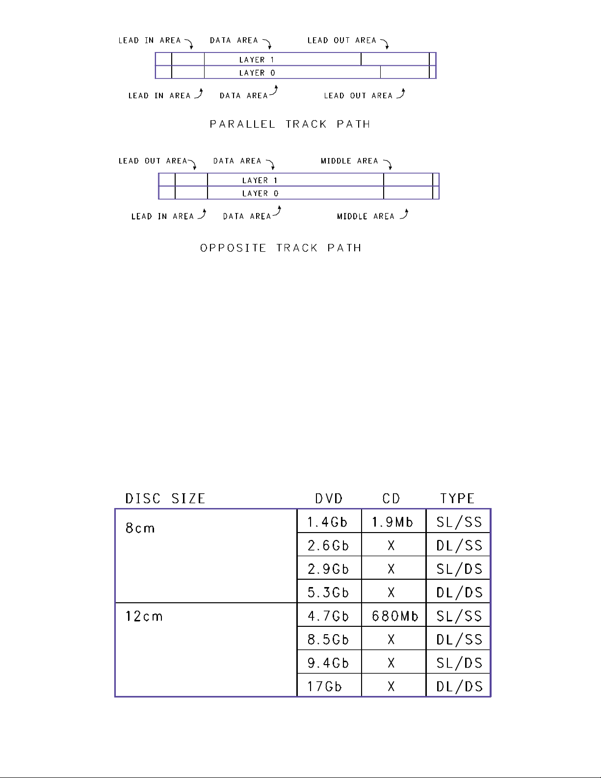
This allows instant access to the additional data
or scene. OTP is Opposite Track Path. This
method links the end of one layer to the beginning of the other. The Lead In Area is still on the
inner portion of the disc. There is a Middle Track
Area on both of the layers located on the outer
portion of the layers. The Middle Track Area links
the data on the two layers together. The Lead
Out Area is on the second layer on the inner portion of the disc.
Capacity
Because a stamped DVD can be Dual Layered
and Double Sided, there are four different capacities. Refer to Figure 13. These capacities strictly pertain to raw data. The time available for
Video and Audio has many extra factors that
determine the length of time on each side or
layer. The picture complexity and the amount of
movement in the picture affect compression and
time on a disc. The number of languages affect
the time on a disc. The type and quality of the
Audio has an affect on the time also. It can be
mono, stereo, or AC-3. Therefore, the media
itself determines the capacity in time on the disc.
Figure 13 – DVD Multi-Layered Capacities
8
Figure 12 – PTP and OTP Layout

Description
The End User/Dealer Self Diagnostics work without the need for other equipment. A number of
hardware tests are automatically executed to
check for faults in the recorder. The diagnosis
ends with a “FAIL” or “PASS” message. If the
message “FAIL” appears on the display, an Error
Code is displayed. If the message “PASS”
appears, the tests have been executed successfully. There can still be a failure in the recorder.
The tests do not cover the complete unit. The
following list describes the tests being preformed
while the test number is being displayed on the
Front Panel. To place the unit in the Self Test
Mode, hold the Play pushbutton on the Front
Panel while suppling AC power to the unit. The
display counts down numerically the test it is
performing.
The following is a list of the test displayed as:
“Test Number” is displayed on the Front Panel
“Name”of the test
Description of the test
22
SdramWrR
Checks all memory locations of the 4Mbyte
SDRAM
21
HostdDramWrR
Checks all the DRAM connected to the microcomputer on the Digital Board
20
HostdI2cNvram
Checks the data line (SDA) and the clock line
(SCL) of the I2C bus between the host decoder
and NVRAM
19
SAA7118I2c
Checks the interface between the Host I2C controller and the SAA7118 Video Input Processor
18
VideoEncI2c
Checks the interface between the host I2C controller and Empress
17
AudioEncI2c
Checks the I2C connection between the host
decoder and Empress
16
AudioEncAccess
Tests the HIO8 interface lines between the host
decoder and the audio encoder
15
AudioEncSramAccess
Checks the access of the SRAM by the audio
encoder (address and data lines).
14
AudioEncSramWrR
Tests the SRAM connected to the audio encoder
13
AudioEncInterrupt
Tests the interrupt line between the host decoder
and the audio encoder
12
VsmAccess
Checks whether the VSM interrupt controllers
and DRAM are accessible
11
VsmInterrupt
Checks both interrupt lines between the VSM
and the host decoder
10
VsmSdramWrR
Tests the entire SDRAM of the VSM
9
Automatic Self Diagnostic Modes
(End User/Dealer Script Interface)

9
Clock11.289MHz
Switches the A_CLK of the micro clock to
11.2896 MHz
8
Clock12.288MHz
Switches the A_CLK of the micro clock to 12.288
MHz
7
BeS2Bengine
Checks the S2B interface with the Basic Engine
by sending an echo command
6
DisplayEcho
Checks the interface between the host processor
and the slave processor on the display board
5
AnalogEcho
Checks the interface between the host processor
and the microprocessor on the Analog Board
4
AnalogNvram
Checks the NVRAM on the Analog Board
3
Tuner
Checks whether the Tuner on the Analog Board
is accessible
2
LoopAudioUserDealer
Tests the components in the audio signal path:
The host decoder on the Analog Board, the
audio encoder, the VSM. The Audio is internally
looped back thru the Digital Board
1
LoopVideoUserDealer
Tests the components on the Video signal system path: - The VIP- The Video encoder- The
VSM- The host decoder. The Analog Board On
Video signal is internally routed back to the
Digital Board.
Color bars appears on the output. It is a PAL colorbar pattern which means you may see a
greyscale bar pattern. The pull in range of the
monitor, will affect what is seen. An NTSC color
bar signal can be output from the Host Decoder
using ComPair.
10

Description
The Manual Diagnostics provide the opportunity
to perform tests and exercise the unit in a way
that helps determine which of the DVD
recorder’s circuit boards are faulty. If no Errors
are found, it performs an endurance loop test. To
successfully perform the tests, the DVD recorder
must be connected to a TV set. The Servicer
must respond to what is seen and heard on the
monitor. (i.e. to approve a test picture or a test
sound). Some tests require that a DVD+RW disc
be inserted.
Structure of the Player Script
The player script (Manual Diagnostics) tests the
circuit boards in the DVD recorder: the Display
PCB, the Digital PCB, the Analog In/Out PCB
and the Basic Engine.
The Player tests are done in two phases, interactive tests and a burn in test. The interactive
tests depend strongly on user interaction and
input to determine the results and to progress
through the full test. The Burn-in Loop test will
perform the same set of tests as the dealer test,
but it will loop through the list indefinitely. Is is
especially usful if you reset the Error Log. You
can do this using ComPair. You can then read
the error codes using ComPair.
Step by Step Description
1
Press OPEN/CLOSE and PLAY buttons at the
same time and provide AC to the recorder to
start the player script. Press Play to perform the
test described on the display. Press Stop to skip
the test and go to the next test. Press Record to
indicate to the Microcomputer the desired result
malfunctioned.
2
The display shows FP SEGM. Press PLAY to
start the test. First the starburst pattern is lit,
then the horizontal segments are lit, followed by
the vertical segments and the last test lights all
the segments. After each of the four tests, the
user has to confirm that the correct pattern was
lit. Press PLAY to confirm that the correct pattern
was lit (four times if the FPSEGMENTS test was
successful). Press RECORD to indicate that the
correct pattern was not successfully lit. Press
STOP to skip this test.
3
The display shows FPLABELS. All labels should
be lit
4
The display shows FPLIGHT ALL. Everything
should be lit.
5
The display shows FPLED. The LED changes
color.
6
The display shows FP LED. The red Record light
comes on. Press play to confirm it lit.Press
STOP to skip this test.
7
The display shows FPKEYBRD. All keys have to
be pressed to get a positive result! This includes
the Power button. Press PLAY for more than two
seconds to confirm that all the keys were
pressed and that it was shown on the display.
Press STOP for more than one second to skip
this test.
8
The display shows FP REMCTL. Press PLAY to
confirm that a key on the remote control was
pressed and shown on the local display. Only
one key has to be pressed to get a successful
result.
11
Manual Service Diagnostics
(Player Script)

9
The display shows FPDIMMER. Press PLAY to
activate the dimming feature. Press Play to confirm that the text on the local display was
dimmed.
10
The display shows ROUTE VID. Press Play to
advance.
11
The display shows ROUTE AUD. Press Play to
advance.
12
The display shows COLORBAR ON.Press Play
to advance. An NTSC Colorbar Pattern should
apear at the output. Press play to advance.
13
The display shows PINKNOISE ON. The monitor
should produce Pink noise.
14
The display shows PINKNOISE OFF. Press Play
to advance.
15
The display shows BE RESET. Press PLAY to
Reset the Basic Engine (Mechanism/Servo
PCB).
16
The display shows BE TRAY OPEN. Press
PLAY to open the tray. Place a RW disc in the
tray.
17
The display shows BE TRAY CLOS. Press PLAY
to close the tray.
18
The display shows BE WRITE READ. This
requires a RW disc to be in the machine. The BE
resets and a small write is preformed, and then a
read. this will take 20 seconds or so.
19
The display shows BE TRAY OPEN. This opens
the tray.
20
The display shows BE TRAY CLOS. This closes
the tray.
21
The display shows ERRORLOG READ. If there
was an error a code will be displayed. If you
press PLAY, the User/Dealer script will start an
endless loop. If the unit fails a test, the local display will display FAIL and the error code
In case of failure, the display shows “ FAIL
XXXXXX “The description of the shown error
code should be found in the list to follow. Once
an error occurs, press the STOP key to jump
over the failure and to continue the diagnostics.
There is a Error Code Table in Force Manual
2064
10000 - Checksum is OK
10001 -Segment name Checksum doesn’t match
or segment name segment not found
10101 - FLASH 1 Write access test failed
10201 - FLASH 2 Write access test failed
10301 - FLASH write test failed
10302 - FLASH write command failed
10303 - FLASH write test done max. number of
times
10401 - HostDec SDRAM Memory data bus test
fails.
10402 - HostDec SDRAM Memory address bus
test fails.
10403 - HostDec SDRAM Physical memory
device test fails.
10501 - HostDec SDRAM Memory data bus test
fails.
10502
HostDec SDRAM Memory address bus test
12

fails.
10503
HostDec SDRAM Physical memory device test
fails.
10601 - HostDec DRAM Memory data bus test
fails.
10602 - HostDec DRAM Memory address bus
test fails.
10603 - HostDec DRAM Physical memory
device test fails.
10701 - HostDec DRAM Memory data bus test
fails.
10702 - HostDec DRAM Memory address bus
test fails.
10703 - HostDec DRAM Physical memory
device test fails.
10800 - Host Decoder version (cut) number: version number Digital hardware version
10801 - Can not find version in FLASH.
10901 - Error muting Audio
11001 - Error un-muting
11501 - Init of I2C failed
11502 - The selection of the clock source failed
11504 - The un-mute of the Audio failed
11601 - Init of I2C failed
11602 - The mute of the Audio failed
11701 - Init of I2C failed
11702 - The muting of the Audio failed
11703 - The un-mute of the Audio failed
11704 - The selection of the clock source failed
11707 - Setup of Front panel failed
11708 - Sine on Front panel keyboard failed
11801 - Init of I2C failed
11802 - The muting of the Audio failed
11803 - The un-mute of the Audio failed
11804 - The selection of the clock source failed
11805 - Error cannot start VSM audio in port
11901 - Init of I2C failed
11902 - The muting of the Audio failed
11903 - The un-mute of the Audio failed
11904 - The selection of the clock source failed
11905 - Error cannot start VSM Audio in port
12001 - Invalid input
12201 - I2C bus busy before start
12202 - NVRAM access time-out
12203 - No NVRAM acknowledgement
12204 - NVRAM time-out
12205 - NVRAM Write/Read back failed
12301 - I2C bus busy before start
12302 - NVRAM read access time-out
12303 - No NVRAM read acknowledgement
12304 - NVRAM read failed
13000 - Bootcode application version boot version
13001 - Can not find version in FLASH.
13100 - Recorder application version: recorder
version
13

13101 - Can not find version in FLASH.
13200 - Diagnostics application version: diagversion
13201 - Can not find version in FLASH.
13300 - Download application version: download
version
13301 - Can not find version in FLASH.
13701 - Turning off Macrovision failed
20001 - I2C bus busy before start
20002 - Video Encoder access time-out
20003 - No acknowledgement from Video
Encoder
20004 - No data send/received to or from Video
Encoder
20005 - SAA7118 VIP can not be initialized
20201 - I2C bus busy before start
20202 - SAA7118 VIP access time-out
20203 - No acknowledgement from SAA7118
VIP
20204 - No data received from SAA7118 VIP
20301 - Error audio encoder SRAM access cannot initialize I2C
20302 - Error audio encoder SRAM access cannot reset DSP through I2C
20303 - Error audio encoder SRAM access cannot download boot
20304 - Error audio encoder cannot download
test code
20305 - Error audio encoder cannot obtain result
of test
20306 - Error audio encoder SRAM access
stuck-at-zero data line
20307 - Error audio encoder SRAM access
stuck-at-one data line
20308 - Error audio encoder SRAM access
stuck-at-one address line
20309 - Error audio encoder SRAM access
address line. Address line x is connected to data
line y
20310 - Error audio encoder SRAM access
address lines address line x and address line y
are connected
20311 - Error audio encoder SRAM access data
lines data line x and data line y are connected
20312 - Error audio encoder SRAM access illegal data received
20401 - Error audio encoder access cannot initialize I2C
20402 - Error audio encoder access cannot reset
DSP through I2C
20403 - Error audio encoder accessing ICR register
20404 - Error audio encoder access stuck-atzero of data line
20405 - Error audio encoder access stuck-at-one
of data line
20406 - Audio encoder access data lines data
line x and data line y are interconnected
20501 - Error audio encoder SRAM WRR cannot
initialize I2C
20502 - Error audio encoder SRAM WRR cannot
reset DSP through I2C
20503 - Error audio encoder WRR cannot down-
14

load boot
20504 - Error audio encoder cannot download
test code
20505 - Error audio encoder SRAM WRR cannot
obtain result of test
20506 - Error audio encoder WRR SRAM stuckat-zero data bit
20507 - Error audio encoder WRR SRAM stuckat-one data bit
20508 - Error audio encoder WRR SRAM data
lines data line x and data line y are connected
20509 - Error audio encoder WRR SRAM illegal
data received
20601 - Error audio encoder interrupt cannot initialize I2C
20602 - Error audio encoder interrupt cannot
reset DSP through I2C
20603 - Error audio encoder cannot download
test code
20604 - Error occurred accessing VSM
20605 - Audio encoder interrupt not received
20606 - Error occurred while activating the
encoder
20607 - Error audio encoder interrupt cannot initialize empress
20608 - Error occurred while getting interrupt
reason
20701 - Error audio encoder I2C cannot reset
DSP through I2C
20702 - Error audio encoder cannot download
boot
20703 - Error audio encoder cannot download
TEST code
20704 - Error audio encoder I2C bus busy
20705 - Error audio encoder I2C cannot write
slave address
20706 - Error audio encoder I2C no acknowledgement received
20707 - Error audio encoder I2C cannot
send/receive data
20708 - Error audio encoder received data
through I2C was invalid
20801 - I2C access failed.
20802 - SAA7118 VIP can not be initialized.
20803 - Invalid input
20900 - B1. B2. B3. B4. B5. B6. B7. B8. B9.
B10. B11. B12.
20901 - Firmware download of EMPRESS failed
20902 - I2C bus busy before start
20903 - EMPRESS access time-out
20904 - No acknowledgement from the
EMPRESS
20905 - No data send to the EMPRESS
20906 - No data received from the EMPRESS
30001 - VSM SDRAM Bank1 Memory data bus
test fails.
30002 - VSM SDRAM Bank1 Memory address
bus test fails.
30003 - VSM SDRAM Bank1 Physical memory
device test fails.
30004 - VSM SDRAM Bank2 Memory data bus
test fails.
30005 - VSM SDRAM Bank2 Memory address
bus test fails.
15

30006 - VSM SDRAM Bank2 Physical memory
device test fails.
30007 - VSM SDRAM Bank1 VSM interrupt register A has a-stuck at- error for value:
30008 - VSM SDRAM Bank2 VSM interrupt register A has a-stuck at- error for value:
30101 - VSM SDRAM Bank1 Memory data bus
test fails.
30102 - VSM SDRAM Bank1 Memory address
bus test fails.
30103 - VSM SDRAM Bank1 Physical memory
device test fails.
30104 - VSM SDRAM Bank2 Memory data bus
test fails.
30105 - VSM SDRAM Bank2 Memory address
bus test fails.
30106 - VSM SDRAM Bank2 Physical memory
device test fails.
30201 - VSM SDRAM Bank1 Memory data bus
test fails.
30202 - VSM SDRAM Bank1 Memory address
bus test fails.
30203 - VSM SDRAM Bank1 Physical memory
device test fails.
30204 - VSM SDRAM Bank2 Memory bus test
wrong.
30205 - VSM SDRAM Bank2 Memory address
bus test fails.
30206 - VSM SDRAM Bank2 Physical memory
device test fails.
30301 - VSM interrupt register A has a -stuck aterror for value:
30302 - VSM interrupt register B has a -stuck aterror for value:
30303 - Interrupt A wasn’t raised.
30304 - Interrupt B wasn’t raised.
30305 - Interrupts A and B were raised.
30401 - VSM SDRAM Bank1 Memory data bus
test fails.
30402 - VSM SDRAM Bank1 Memory address
bus test fails.
30403 - VSM SDRAM Bank1 Physical memory
device test fails.
30404 - VSM SDRAM Bank2 Memory data bus
test fails.
30405 - VSM SDRAM Bank2 Memory address
bus test fails.
30406 - VSM SDRAM Bank2 Physical memory
device test fails.
30501 - Communication with the Analog Board
fails.
30502 - Echo test to Analog Board returned
wrong string.
40001 - NVRAM Reset; I2C failed
40100 - NVRAM address = 0xaddress ->
Bytevalue = 0xvalue
40101 - NVRAM Read; I2C failed
40102 - NVRAM Read; Invalid input
40201 - NVRAM Modify; I2C failed
40202 - NVRAM Modify; Invalid input
40300 - DV Unique ID = id
40301 - NVRAM Read DV Unique ID; I2C failed
40400 - \r\n Error log: \r\n error String \r\n Ö
40401 - NVRAM error log; I2C failed
16

40402 - NVRAM error log is invalid
40403 - Front panel failed
40701 - NVRAM error log reset; I2C failed
40900 - Region code Change counter is reset
40901 - NVRAM region code reset; I2C failed
41001 - NVRAM Store DV Unique ID; I2C failed
41002 - NVRAM Store DV Unique ID; Invalid
input
50007 - Execution of the command on the
Analog Board failed.
50008 - The front panel could not be accessed
by the Analog Board.
50009 - The echo from the front panel processor
was not correct.
50100 - Front panel version: FP version
50102 - Execution of the command on the
Analog Board failed.
50103 - The front panel could not be accessed
by the Analog Board.
50204 - Execution of the command on the
Analog Board failed.
50205 - The front panel could not be accessed
by the Analog Board.
50206 - The front panel did not show a starburst.
50207 - The user skipped the FP-which pattern
test.
50208 - The user returned an unknown confirmation: confirmation
50209 - The front panel did not show horizontal
segments.
50210 - The front panel did not show vertical
segments.
50304 - Execution of the command on the
Analog Board failed.
50305 - The front panel could not be accessed
by the Analog Board.
50306 - The front panel did not light all labels.
50307 - The user skipped the rest of the FPlabel test.
50308 - The user returned an unknown confirmation: confirmation
50404 - Execution of the command on the
Analog Board failed.
50405 - The front panel could not be accessed
by the Analog Board.
50406 - The LED’s could not be turned on.
50407 - The user skipped the rest of the FP-LED
test.
50408 - The user returned an unknown confirmation: confirmation
50502 - Front panel Keyboard; test failed
50503 - Front panel Keyboard; test aborted
50504 - Front panel Keyboard; not all keys were
pressed
50505 - Front panel keyboard I2C connection
failed
50506 - Unable to get slash version
50602 - Front panel Remote control; test failed
50603 - Front panel Remote control; test aborted
50604 - Front panel remote control; can not
access FP
17

50605 - Front panel remote control; no user
input received
50701 - Execution of the command on the
Analog Board failed.
50702 - The front panel could not be accessed
by the Analog Board.
50703 - The front panel did not show a starburst.
50704 - The user skipped the FP-starburst test.
50705 - The user returned an unknown confirmation: confirmation
50801 - Execution of the command on the
Analog Board failed.
50802 - The front panel could not be accessed
by the Analog Board.
50803 - The front panel did not show vertical
segments.
50804 - The user skipped the FP-vertical segments test.
50805 - The user returned an unknown confirmation: confirmation
50901 - Execution of the command on the
Analog Board failed.
50902 - The front panel could not be accessed
by the Analog Board.
50903 - The front panel did not show horizontal
segments.
50904 - The user skipped the FP-horizontal segments test.
50905 - The user returned an unknown confirmation: confirmation
51401 - Execution of the command on the
Analog Board failed.
51402 - The front panel could not be accessed
by the Analog Board.
51403 - The beeper did not sound.
51404 - The user skipped the FP-Beep test.
51405 - The user returned an unknown confirmation: confirmation
51501 - Execution of the command on the
Analog Board failed.
51502 - The front panel could not be accessed
by the Analog Board.
51503 - The disc bar did not display properly.
51504 - The user skipped the disc bar test.
51505 - The user returned an unknown confirmation: confirmation
51601 - Execution of the command on the
Analog Board failed.
51602 - The front panel could not be accessed
by the Analog Board.
51603 - The disc bar dots did not display properly.
51604 - The user skipped the disc bar dots test.
51605 - The user returned an unknown confirmation: confirmation
51701 - Execution of the command on the
Analog Board failed.
51702 - The front panel could not be accessed
by the Analog Board.
51703 - The VU grid did not display properly.
51704 - The user skipped the VU grid test.
51705 - The user returned an unknown confirmation: confirmation
51801 - Execution of the command on the
Analog Board failed.
18

51802 - The front panel could not be accessed
by the Analog Board.
51803 - The front panel could not be dimmed.
51804 - The user skipped the FP-Dim test.
51805 - The user returned an unknown confirmation: confirmation
51901 - Execution of the command on the
Analog Board failed.
51902 - The front panel could not be accessed
by the Analog Board.
51903 - The front panel did not show segments
blinking.
51904 - The user skipped the FP-blinking test.
51905 - The user returned an unknown confirmation: confirmation
52001 - Execution of the command on the
Analog Board failed.
52002 - The front panel could not be accessed
by the Analog Board.
52003 - The front panel did not show all segments lit.
52004 - The user skipped the FP-light all segments test.
52005 - The user returned an unknown confirmation: confirmation
52201 - Communication with Analog Board fails.
52202 - front panel can not be accessed by the
Analog Board.
52301 - Communication with Analog Board fails.
52302 - front panel can not be accessed by the
Analog Board.
60101 - Basic Engine returned error number 0x
error number
60102 - Parity error from Basic Engine to Serial
60103 - Communication time-out error
60104 - Unexpected response from Basic
Engine
60105 - Echo loop could not be closed
60106 - Wrong echo pattern received
60200 - Version: nr1.nr2.nr3
60201 - Basic Engine returned error number
0xerrornumber
60202 - Parity error from Basic Engine to Serial
60203 - Communication time-out error
60204 - Unexpected response from Basic
Engine
60205 - Front Panel failed.
60301 - Basic-Engine time-out error
60401 - Basic Engine returned error number
0xerrornumber
60402 - Parity error from Basic Engine to Serial
60403 - Communication time-out error
60404 - Unexpected response from Basic
Engine
60405 - Focus loop could not be closed
60501 - Basic Engine returned error number
0xerrornumber
60502 - Parity error from Basic Engine to Serial
60503 - Communication time-out error
19

60504 - Unexpected response from Basic
Engine
60601 - Basic Engine returned error number
0xerrornumber
60602 - Parity error from Basic Engine to Serial
60603 - Communication time-out error
60604 - Unexpected response from Basic
Engine
60701 - Basic Engine returned error number
0xerrornumber
60702 - Parity error from Basic Engine to Serial
60703 - Communication time-out error
60704 - Unexpected response from Basic
Engine
60801 - Basic Engine returned error number
0xerrornumber
60802 - Parity error from Basic Engine to Serial
60803 - Communication time-out error
60804 - Unexpected response from Basic
Engine
60805 - Radial loop could not be closed
60901 - Basic Engine returned error number
0xerrornumber
60902 - Parity error from Basic Engine to Serial
60903 - Communication time-out error
60904 - Unexpected response from Basic
Engine
61501 - Basic Engine returned error number
0xerrornumber
61502 - Parity error from Basic Engine to Serial
61503 - Communication time-out error
61504 - Unexpected response from Basic
Engine
61601 - Basic Engine returned error number
0xerrornumber
61602 - Parity error from Basic Engine to Serial
61603 - Communication time-out error
61604 - Unexpected response from Basic
Engine
61701 - BE tray-in command failed
61702 - BE read-TOC command failed
61703 - BE VSM interrupt initialization failed
61704 - BE set IRQ command failed
61705 - BE no disc or wrong disc inserted
61706 - BE rec-pause command failed
61707 - BE VSM BE out DMA initialization failed
61708 - BE VSM BE out initialization failed
61709 - BE VSM BE out DMA start failed
61710 - BE VSM BE out start failed
61711 - BE rec command failed
61712 - BE VSM out under run error occurred
61713 - BE record complete interrupt not raised
61714 - BE get IRQ command failed
61715 - BE no interrupt was raised by BE
61716 - BE VSM DMA out not finished
61717 - BE stop command after writing failed
20

61718 - BE VSM Sector processor initialization
failed
61719 - BE VSM sector processor DMA initialization failed
61720 - BE VSM sector processor DMA start
failed
61721 - BE VSM sector processor start failed
61722 - BE seek command failed
61723 - BE VSM sector processor error occurred
61724 - BE read timeout occurred
61725 - BE stop command after reading failed
61726 - BE difference found in data at disc sector 0xdiscsector
61727 - This nucleus cannot be executed
because the Self-Test failed
61801 - BE I2C initialization failed
61802 - This nucleus cannot be executed
because the Self-Test failed
61901 - The Self Test failed with result: 0xnr1
0xnr20xnr3
61902 - Basic Engine returned error number
0xerrornumber
61903 - Parity error from Basic Engine to Serial
61904 - Communication time-out error
61905 - Unexpected response from Basic
Engine
62001 - Self-Test: errorstring1 Laser-Test:
errorstring2 Spindle M-Test: errorstring3 Sledge
M-Test: error string4 Focus-Test: errorstring5
62100 - The forward sense level is 0xlevel
62101 - Basic Engine returned error number
0xerrornumber
62102 - Parity error from Basic Engine to Serial
62103 - Communication time-out error
62104 - Unexpected response from Basic
Engine
62201 - The BE-self-diagnostic-spindle-motortest failed
62202 - Basic Engine returned error number
0xerrornumber
62203 - Parity error from Basic Engine to Serial
62204 - Communication time-out error
62205 - Unexpected response from Basic
Engine
62301 - The BE-focus-test failed
62302 - Basic Engine returned error number
0xerrornumber
62303 - Parity error from Basic Engine to Serial
62304 - Communication time-out error
62305 - Unexpected response from Basic
Engine
62401 - The BE-self-diagnostic-sledge-motor-test
failed
62402 - Basic Engine returned error number
0xerrornumber
62403 - Parity error from Basic Engine to Serial
62404 - Communication time-out error
62405 - Unexpected response from Basic
Engine
62700 - BE EEPROM address = address -> Byte
value = 0xvalue
62701 - Basic Engine returned error number
21

0xerrornumber
62702 - Parity error from Basic Engine to Serial
62703 - Communication time-out error
62704 - Unexpected response from Basic
Engine
62705 - BE read EEPROM; invalid input
62801 - Basic Engine returned error number
0xerrornumber
62802 - Parity error from Basic Engine to Serial
62803 - Communication time-out error
62804 - Unexpected response from Basic
Engine
62805 - BE write EEPROM; invalid input
62901 - Basic Engine returned error number
0xerrornumber
62902 - Parity error from Basic Engine to Serial
62903 - Communication time-out error
62904 - Unexpected response from Basic
Engine
62905 - Radial loop could not be closed
63001 - Basic Engine returned error number
0xerrornumber
63002 - Parity error from Basic Engine to Serial
63003 - Communication time-out error
63004 - Unexpected response from Basic
Engine
63100 - Number of times Tray went
Open/Closed: nr1 Total hours the CD laser was
on: nr2 Total hours the DVD laser was on: nr3
Total hours the write laser was on: nr4
63101 - Basic Engine returned error number
0xerrornumber
63102 - Parity error from Basic Engine to Serial
63103 - Communication time-out error
63104 - Unexpected response from Basic
Engine
63201 - Basic Engine returned error number
0xerrornumber
63202 - Parity error from Basic Engine to Serial
63203 - Communication time-out error
63204 - Unexpected response from Basic
Engine
63300 - Momentary errors (Byte 1 - Byte 7):
0xb1 0xb2 0xb30xb4 0xb5 0xb6 0xb7
Cumulative errors (Byte 1 - Byte 7): 0xb10xb2
0xb3 0xb4 0xb5 0xb6 0xb7 Fatal errors (Oldest Youngest): 0xb1 0xb2 0xb3 0xb4 0xb5
63301 - Basic Engine returned error number
0xerrornumber
63302 - Parity error from Basic Engine to Serial
63303 - Communication time-out error
63304 - Unexpected response from Basic
Engine
63401 - Basic Engine returned error number
0xerrornumber
63402 - Parity error from Basic Engine to Serial
63403 - Communication time-out error
63404 - Unexpected response from Basic
Engine
63501 - Basic Engine returned error number
0xerrornumber
22

63502 - Parity error from Basic Engine to Serial
63503 - Communication time-out error
63504 - Unexpected response from Basic
Engine
63505 - Error string Ö The basic engine will
reject all player commands
63901 - Basic Engine returned error number
0xerrornumber
63902 - Parity error from Basic Engine to Serial
63903 - Communication time-out error
63904 - Unexpected response from Basic
Engine
64000 - BE OPU number = opu number
64001 - Basic Engine returned error number
0xerrornumber
64002 - Parity error from Basic Engine to Serial
64003 - Communication time-out error
64004 - Unexpected response from Basic
Engine
64100 - The data was successfully written on
and read from a DVD disc
64101 - The tray-in command failed
64102 - The read-TOC command failed
64103 - The VSM interrupt initialization failed
64104 - The set IRQ command failed
64105 - No disc or wrong disc inserted
64106 - The rec-pause command failed
64107 - The VSM BE out DMA initialization failed
64108 - The VSM BE out initialization failed
64109 - The VSM BE out DMA start failed
64110 - The VSM BE out start failed
64111 - The rec command failed
64112 - The VSM out under run error occurred
64113 - The record complete interrupt was not
raised
64114 - The get IRQ command failed
64115 - There was no interrupt raised by BE
64116 - The VSM DMA did not finished
64117 - The stop command after writing failed
64118 - The VSM Sector processor initialization
failed
64119 - The VSM sector processor DMA initialization failed
64120 - The VSM sector processor DMA start
failed
64121 - The VSM sector processor start failed
64122 The seek command failed
64123 - The VSM sector processor error
occurred
64124 - The read timeout occurred
64125 - The stop command after reading failed
64126 - There was a difference found in data at
a specific disc sector
64127 - The result of the self test contains errors
64128 - An error interrupt was raised by BE
23

64129 - The calibrate-record command failed
64130 - To many retries
64131 - BE update RAI command after writing
failed
64132 - BE find first recordable address command failed
64133 - DVD+R disc is full
64201 - BE i2c initialization failed
64202 - This nucleus cannot be executed
because the Self-Test failed
70000 - Echo test OK
70001 - Echo test returned wrong string.
70002 - Communication with Analog Board fails
70300 - Software Version
70301 - Can not find segment in FLASH ROM
on the Analog Board
70302 - Communication with Analog Board fails
70400 - Hardware Version
70401 - Can not find segment in FLASH ROM
on the Analog Board
70402 - Communication with Analog Board fails
70500 - Clock adjusted OK
70501 - Can not adjust the clock on the Analog
Board.
70502 - Wrong date/time text size.
70503 - Communication with Analog Board fails
70600 - Tuner accessibility test OK
70601 - Can not access Tuner on the Analog
Board.
70602 - Communication with Analog Board fails
70700 - Frequency download OK
70701 - Wrong frequency table size.
70702 - Can not download the frequency table
into the Analog NVRAM.
70703 - Can not download the frequency table
into the Analog NVRAM.
70704 - Communication with Analog Board fails
70800 - Data Slicer test OK
70801 - Test of the Data Slicer on the Analog
Board fails.
70802 - Communication with Analog Board fails
70900 - Sound Processor test OK
70901 - Test of the Sound Processor on the
Analog Board fails.
70902 - Communication with Analog Board fails
71000 - AV Selector test OK
71001 - Test of the AV Selector on the Analog
Board fails.
71002 - Communication with Analog Board fails
71100 - NVRAM test OK
71101 - Test of the NVRAM on the Analog Board
fails.
71102 - Communication with Analog Board fails
71200 - Video routing on the Analog Board OK
71201 - Routing the Video on the Analog Board
fails.
71202 - Invalid input.
24

71203 - Communication with Analog Board fails
71300 - Audio routing on the Analog Board OK
71301 - Routing the Audio on the Analog Board
fails.
71302 - Invalid input.
71303 - Communication with Analog Board fails
71501 - Invalid slash version, default slash version is set.
71502 - Setting the slash version on the Analog
Board fails.
71503 - Communication with Analog Board fails
71600 - Application Version
71601 - Can not find segment in FLASH ROM
on the Analog Board
71602 - Communication with Analog Board fails
71700 - Diagnostics Version
71701 - Can not find segment in FLASH ROM
on the Analog Board
71702 - Communication with Analog Board fails
71800 - Download Version
71801 - Can not find segment in FLASH ROM
on the Analog Board
71802 - Communication with Analog Board fails
72001 - Adjusting BarGraph Level failed
72002 - Communication with Analog Board fails
72101 - Storing clock correction failed
72102 - Value out of range: default value stored
72103 - Invalid input.
72104 - Communication with Analog Board fails
72201 - Initializing the 1Hz signal on the Clock
IC failed
72202 - Communication with Analog Board fails
72301 - Clearing the NVRAM on the Analog
Board fails
72302 - Communication with Analog Board fails
72400 - Segment checksum is: checksum which
is correct for every segment
72401 - Segment could not be found or segment
checksum is: checksum C, however it should be:
checksum E for every segment
72402 - Communication with Analog Board fails
72900 - Date received
72901 - Data returned
72902 - Communication on I2C-bus failed on the
Analog Board fails.
72903 - Communication with Analog Board fails
73001 - Storing the external presets on the
Analog Board fails
73002 - Communication with Analog Board fails
73100 - 0xslash version where slash version is
the slash version read from the Analog Board
73101 - Error while reading out slash version.
73102 - I2C Write error.
73103 - I2C Read error.
73104 - Communication with Analog Board fails
73201 - Storing the Reference Voltage for the
Tuner failed
25

73202 - Invalid input.
73203 - Communication with Analog Board fails
80000 - The DVIO module is present in the system.
80001 - The DVIO module is not present in the
system.
80100 - The DVIO module has been reset OK.
80101 - The DVIO module is not present in the
system.
80102 - The DVIO module could not be reset.
80103 - Could not initialize I2C before Reset.
80200 - The accessibility of the DVIO module is
OK.
80201 - The DVIO Board is not present in this
DVDR.
80202 - Could not initialize I2C.
80203 - Unable to reset the DVIO module.
80204 - Unable to receive the reset indication
from the DVIO module.
80205 - Unable to send the configuration to the
DVIO module.
80206 - Unable to download the chip ID to the
DVIO module.
80207 - Unable to set the mode of the DVIO
module to IDLE.
80208 - Software Error in function Handle State
Awaiting Reply!!
80209 - Maximal number of retries reached by
Handle State Sending!!
80210 - Maximal number of retries (NACKs)
reached (Handle State Sending)
80211 - We tried to receive a reply for
DVIO_MAX_RETRIES_ACKREPLY times !!
80212 - We tried to receive a reply for
DVIO_MAX_RETRIES_REPLY times !!
80213 - We tried to receive an Ack for
DVIO_MAX_RETRIES_ACK times!!
80214 - VSM UART error timeout transmitting
command
80215 - VSM UART error timeout receiving reply
80216 - VSM UART frame error occurred receiving from DVIO Board
80217 - VSM UART parity error occurred receiving from DVIO Board
80218 - The confirmation/indication from the
DVIO module is invalid.
80300 - The accessibility of the DVIO module is
OK.
80301 - The DVIO Board is not present in this
DVDR.
80302 - Could not initialize I2C.
80303 - Unable to reset the DVIO module.
80304 - Unable to receive the reset indication
from the DVIO module.
80305 - Unable to send the configuration to the
DVIO module.
80306 - Unable to download the chip ID to the
DVIO module.
80307 - Unable to set the mode of the DVIO
module to IDLE.
80308 - Software Error in function Handle State
Awaiting Reply!!
26

80309 - Maximal number of retries reached by
Handle State Sending!!
80310 - Maximal number of retries (NACKs)
reached (Handle State Sending)
80311 - We tried to receive a reply for
DVIO_MAX_RETRIES_ACKREPLY times !!
80312 - We tried to receive a reply for
DVIO_MAX_RETRIES_REPLY times !!
80313 - We tried to receive an Ack for
DVIO_MAX_RETRIES_ACK times!!
80314 - VSM UART error timeout transmitting
command
80315 - VSM UART error timeout receiving reply
80316 - VSM UART frame error occurred receiving from DVIO Board
80317 - VSM UART parity error occurred receiving from DVIO Board
80318 - The confirmation/indication from the
DVIO module is invalid.
80400 - The accessibility of the DVIO module is
OK.
80401 - The DVIO Board is not present in this
DVDR.
80402 - Could not initialize I2C.
80403 - Unable to reset the DVIO module.
80404 - Unable to receive the reset indication
from the DVIO module.
80405 - Unable to send the configuration to the
DVIO module.
80406 - Unable to download the chip ID to the
DVIO module.
80407 - Unable to set the mode of the DVIO
module to IDLE.
80408 - Software Error in function Handle State
Awaiting Reply!!
80409 - Maximal number of retries reached by
Handle State Sending!!
80410 - Maximal number of retries (NACKs)
reached (Handle State Sending)
80411 - We tried to receive a reply for
DVIO_MAX_RETRIES_ACKREPLY times !!
80412 - We tried to receive a reply for
DVIO_MAX_RETRIES_REPLY times !!
80413 - We tried to receive an Ack for
DVIO_MAX_RETRIES_ACK times!!
80414 - VSM UART error timeout transmitting
command
80415 - VSM UART error timeout receiving reply
80416 - VSM UART frame error occurred receiving from DVIO Board
80417 - VSM UART parity error occurred receiving from DVIO Board
80418 - The confirmation/indication from the
DVIO module is invalid.
80501 - The DVIO Board is not present in this
DVDR.
80502 - The I2C could not be initialized.
80503 - The DVIO module could not be reset.
80504 - Unable to receive the reset indication
from the DVIO module.
80505 - Unable to send the configuration to the
DVIO module.
80506 - Unable to download the chip ID to the
DVIO module.
80507 - Unable to set the mode of the DVIO
module to IDLE.
27

80508 - Software Error in Handle State Awaiting
Reply function!
80509 - Maximal number of retries reached by
Handle State Sending!
80510 - Maximal number of retries (NACKs)
reached (Handle State Sending)
80511 - We tried to receive a reply for
DVIO_MAX_RETRIES_ACKREPLY times!
80512 - We tried to receive a reply for
DVIO_MAX_RETRIES_REPLY times!
80513 - We tried to receive an
Acknowledgement for
DVIO_MAX_RETRIES_ACK times
80514 - VSM UART error timeout transmitting
command
80515 - VSM UART error timeout receiving reply
80516 - VSM UART frame error occurred receiving from DVIO Board
80517 - VSM UART parity error occurred receiving from DVIO Board
80518 - The confirmation/indication from the
DVIO module is invalid.
80519 - Setting the DVIO module in/out diagnostics mode failed
80520 - Invalid input
80521 - Getting the errors of the self-test failed
80522 - Self-test failed
80601 - The DVIO Board is not present in this
DVDR.
80602 - The I2C could not be initialized.
80603 - The DVIO module could not be reset.
80604 - Unable to receive the reset indication
from the DVIO module.
80605 - Unable to send the configuration to the
DVIO module.
80606 - Unable to download the chip ID to the
DVIO module.
80607 - Unable to set the mode of the DVIO
module to IDLE.
80608 - Software Error in Handle State Awaiting
Reply function!
80609 - Maximal number of retries reached by
Handle State Sending!
80610 - Maximal number of retries (NACKs)
reached (Handle State Sending)
80611 - We tried to receive a reply for
DVIO_MAX_RETRIES_ACKREPLY times!
80612 - We tried to receive a reply for
DVIO_MAX_RETRIES_REPLY times!
80613 - We tried to receive an
Acknowledgement for
DVIO_MAX_RETRIES_ACK times!
80614 - VSM UART error timeout transmitting
command
80615 - VSM UART error timeout receiving reply
80616 - VSM UART frame error occurred receiving from DVIO Board
80617 - VSM UART parity error occurred receiving from DVIO Board
80618 - The confirmation/indication from the
DVIO module is invalid.
80619 - Setting the DVIO module in/out diagnostics mode failed
80701 - The DVIO Board is not present in this
DVDR.
28

80702 - The I2C could not be initialized.
80703 - The DVIO module could not be reset.
80704 - Unable to receive the reset indication
from the DVIO module.
80705 - Unable to send the configuration to the
DVIO module.
80706 - Unable to download the chip ID to the
DVIO module.
80707 - Unable to set the mode of the DVIO
module to IDLE.
80708 - Software Error in Handle State Awaiting
Reply function!
80709 - Maximal number of retries reached by
Handle State Sending!
80710 - Maximal number of retries (NACKs)
reached (Handle State Sending)
80711 - We tried to receive a reply for
DVIO_MAX_RETRIES_ACKREPLY times!
80712 - We tried to receive a reply for
DVIO_MAX_RETRIES_REPLY times!
80713 - We tried to receive an
Acknowledgement for
DVIO_MAX_RETRIES_ACK times!
80714 - VSM UART error timeout transmitting
command
80715 - VSM UART error timeout receiving reply
80716 - VSM UART frame error occurred receiving from DVIO Board
80717 - VSM UART parity error occurred receiving from DVIO Board
80718 - The confirmation/indication from the
DVIO module is invalid.
80719 - Setting the DVIO module in/out diagnos-
tics mode failed
90121 - Error: Audio data in host memory contains wrong frequency: frequency Hz
90122 - Error: Audio data in host memory contains silence!
90123 - There is no correct audio frame in the
buffer
90124 - The audio frame has an illegal version
bit
90125 - The audio frame has an illegal bitrateindex
90126 - The audio frame has an illegal sampling
rate
90127 - The CRC of the audio frame is wrong
90128 - The audio frame is not MPEG-I layer II !
90129 - Error cannot de-mute DAC on Analog
Board
90201 - Initialization of I2C failed
90202 - Initialization of VIP and EMPIRE failed
90203 - Initialization of PLL / Link failed.
90204 - Next descriptor address set wrong.
90205 - Turning on the colorbar failed
90206 - No I2C communication possible to start
video encoder.
90207 - Starting the video encoder failed.
90208 - Transfer of data from video encoder to
VSM failed.
90209 - Stopping the encoder failed.
90210 - Turning off the colorbar failed.
90211 - Cannot initialize hostdecoder parallel
29
 Loading...