

Page 1

DVDR80
Digital Video Disc Recorder
Owner's Manual
NEED HELP?CALL US!
P
HILIPS REPRESENTATIVES ARE READY TO HELP YOU WITH ANY QUESTIONS ABOUT YOUR NEW
PRODUCT
.WE CAN GUIDE YOU THROUGH CONNECTIONS,FIRST-TIME SETUP,AND ANY OF THE
FEATURES.WE WANT YOU TO START ENJOYING YOUR NEW PRODUCT RIGHT AWAY.
C
ALL US BEFORE YOU CONSIDER
RETURNING THE PRODUCT
.
1-800-531-0039
O
R VISIT US ON THE WEB AT WWW.PHILIPS.COM
Important!
Return your
Warranty
Registration Card
within 10 days.
See why inside.
Page 2
Once your PHILIPS purchase is registered, you’re eligible to receive all the privileges of owning a PHILIPS product.
So complete and return the Warranty Registration Card enclosed with your purchase at once. And take advantage
of these important benefits.
Return your Warranty Registration card today to
ensure you receive all the
benefits
you’re entitled to.
For Customer Use
Enter below the Serial No. which is
located on the rear of the cabinet.
Retain this information for future
reference.
Model No. ____________________
Serial No. ____________________
Congratulations on your purchase,
and welcome to the “family!”
Dear PHILIPS product owner:
Thank you for your confidence in PHILIPS.You’ve selected one of the
best-built, best-backed products available today.We’ll do everything in
our power to keep you happy with your purchase for many years to
come.
As a member of the PHILIPS “family,” you’re entitled to protection by
one of the most comprehensive warranties and outstanding service
networks in the industry.What’s more, your purchase guarantees you’ll
receive all the information and special offers for which you qualify, plus
easy access to accessories from our convenient home shopping
network.
Most importantly, you can count on our uncompromising commitment
to your total satisfaction.All of this is our way of saying welcome - and
thanks for investing in a PHILIPS product.
Sincerely,
Lawrence J. Blanford
President and Chief Executive Officer
P.S. Remember, to get the most from your PHILIPS prod-
uct, you must return your Warranty Registration
Card within 10 days. So please mail
it to us right now!
Know these
safetysymbols
This “bolt of lightning” indicates
uninsulated material within your
unit may cause an electrical shock. For
the safety of everyone in your household, please do not remove product
covering.
The “exclamation point” calls
attention to features for which
you should read the enclosed
literature closely to prevent operating
and maintenance problems.
WARNING: TO PREVENT FIRE OR
SHOCK HAZARD, DO NOT EXPOSE
THIS EQUIPMENT TO RAIN OR
MOISTURE.
CAUTION: To prevent electric
shock, match wide blade of plug to
wide slot, fully insert.
ATTENTION: Pour éviter les choc
électriques, introduire la lame la plus
large de la fiche dans la borne correspondante de la prise et pousser
jusqu’au fond.
CAUTION
RISK OF ELECTRIC SHOCK
DO NOT OPEN
CAUTION: TO REDUCE THE RISK OF ELECTRIC SHOCK, DO NOT
REMOVE COVER (OR BACK). NO USER-SERVICEABLE PARTS
INSIDE. REFER SERVICING TO QUALIFIED SERVICE PERSONNEL.
Warranty
Verification
Registering your product within 10 days
confirms your right to maximum
protection under the terms and
conditions of your PHILIPS warranty.
Owner
Confirmation
Your completed Warranty Registration
Card serves as verification of ownership
in the event of product theft or loss.
Model
Registration
Returning your Warranty Registration
Card right away guarantees you’ll receive
all the information and special
offers which you qualify for as the
owner of your model.
Visit our World Wide Web Site at http://www.philips.com
t
s
R
E
G
I
S
T
R
A
T
I
O
N
N
E
E
D
E
D
W
I
T
H
I
N
1
0
D
A
Y
S
Hurry!
Page 3

Contents 3
General Information
Contents . . . . . . . . . . . . . . . . . . . . . . . . . . . . . . . . . . . . . . . . . . . . . . . . . . . . . . .3
Safety Information . . . . . . . . . . . . . . . . . . . . . . . . . . . . . . . . . . . . . . . . . . . . . . .4-5
Introduction . . . . . . . . . . . . . . . . . . . . . . . . . . . . . . . . . . . . . . . . . . . . . . . . . . . . .6
Getting Started
Playable Discs . . . . . . . . . . . . . . . . . . . . . . . . . . . . . . . . . . . . . . . . . . . . . . . . . . .7
General Information . . . . . . . . . . . . . . . . . . . . . . . . . . . . . . . . . . . . . . . . . . . . . .8
Hookups . . . . . . . . . . . . . . . . . . . . . . . . . . . . . . . . . . . . . . . . . . . . . . . . . . . . .9-17
Initial Setup . . . . . . . . . . . . . . . . . . . . . . . . . . . . . . . . . . . . . . . . . . . . . . . . . .18-20
Basic Features
Quick Recording . . . . . . . . . . . . . . . . . . . . . . . . . . . . . . . . . . . . . . . . . . . . . . . .21
Quick Disc Play . . . . . . . . . . . . . . . . . . . . . . . . . . . . . . . . . . . . . . . . . . . . . . . . .22
Title/Disc Menus, Chapter/Track Selection . . . . . . . . . . . . . . . . . . . . . . . . . . . . .23
DVD Recorder Controls
Remote Control . . . . . . . . . . . . . . . . . . . . . . . . . . . . . . . . . . . . . . . . . . . . . .24-25
Front Panel . . . . . . . . . . . . . . . . . . . . . . . . . . . . . . . . . . . . . . . . . . . . . . . . . . . .26
Rear Panel . . . . . . . . . . . . . . . . . . . . . . . . . . . . . . . . . . . . . . . . . . . . . . . . . . . . .27
Menu Bars . . . . . . . . . . . . . . . . . . . . . . . . . . . . . . . . . . . . . . . . . . . . . . . . . . . . .28
On-screen Symbols, Status Box . . . . . . . . . . . . . . . . . . . . . . . . . . . . . . . . . . . . .29
Information Boxes . . . . . . . . . . . . . . . . . . . . . . . . . . . . . . . . . . . . . . . . . . . . . . .30
Index Picture Screen . . . . . . . . . . . . . . . . . . . . . . . . . . . . . . . . . . . . . . . . . . . . .31
Additional Installation
Clock . . . . . . . . . . . . . . . . . . . . . . . . . . . . . . . . . . . . . . . . . . . . . . . . . . . . . . . . .32
Channel Programming . . . . . . . . . . . . . . . . . . . . . . . . . . . . . . . . . . . . . . . . . . . .33
Recording Options
One-Touch Recording . . . . . . . . . . . . . . . . . . . . . . . . . . . . . . . . . . . . . . . . . . . .34
Title Settings Menu . . . . . . . . . . . . . . . . . . . . . . . . . . . . . . . . . . . . . . . . . . . . . .35
Append Recording, Record One Channel/Watch Another . . . . . . . . . . . . . . . . .36
Record Settings, Chapter Markers . . . . . . . . . . . . . . . . . . . . . . . . . . . . . . . . . . .37
Editing
Editing: Disc Information Screen . . . . . . . . . . . . . . . . . . . . . . . . . . . . . . . . . . . . .38
Editing . . . . . . . . . . . . . . . . . . . . . . . . . . . . . . . . . . . . . . . . . . . . . . . . . . . . . . . .39
Finalize Disc . . . . . . . . . . . . . . . . . . . . . . . . . . . . . . . . . . . . . . . . . . . . . . . . . . . .40
Disc Manager . . . . . . . . . . . . . . . . . . . . . . . . . . . . . . . . . . . . . . . . . . . . . . . .41-42
Advanced Disc Play and Features
GUIDE Plus+®System . . . . . . . . . . . . . . . . . . . . . . . . . . . . . . . . . . . . . . . . . .43-47
Audio Language, Subtitles . . . . . . . . . . . . . . . . . . . . . . . . . . . . . . . . . . . . . . . . . .48
Zoom, Camera Angle . . . . . . . . . . . . . . . . . . . . . . . . . . . . . . . . . . . . . . . . . . . . .49
Sound, Still Picture . . . . . . . . . . . . . . . . . . . . . . . . . . . . . . . . . . . . . . . . . . . . . . .50
Slow Motion, Searching . . . . . . . . . . . . . . . . . . . . . . . . . . . . . . . . . . . . . . . . . . .51
Time Search, Scan . . . . . . . . . . . . . . . . . . . . . . . . . . . . . . . . . . . . . . . . . . . . . . .52
Repeat, Repeat A-B . . . . . . . . . . . . . . . . . . . . . . . . . . . . . . . . . . . . . . . . . . . . . .53
Additional Features and Setup Options
Access Control . . . . . . . . . . . . . . . . . . . . . . . . . . . . . . . . . . . . . . . . . . . . . . .54-56
DVD Recorder Features Menu . . . . . . . . . . . . . . . . . . . . . . . . . . . . . . . . . . . . . .57
Picture Settings . . . . . . . . . . . . . . . . . . . . . . . . . . . . . . . . . . . . . . . . . . . . . . . . .58
Analog Output, Digital Output . . . . . . . . . . . . . . . . . . . . . . . . . . . . . . . . . . . . . .59
Language Settings . . . . . . . . . . . . . . . . . . . . . . . . . . . . . . . . . . . . . . . . . . . . . . . .60
Night Mode, Remote Control Used . . . . . . . . . . . . . . . . . . . . . . . . . . . . . . . . . .61
Auto Resume, Playback Control . . . . . . . . . . . . . . . . . . . . . . . . . . . . . . . . . . . . .62
Information You May Need
Glossary . . . . . . . . . . . . . . . . . . . . . . . . . . . . . . . . . . . . . . . . . . . . . . . . . . . . . . .63
Helpful Hints . . . . . . . . . . . . . . . . . . . . . . . . . . . . . . . . . . . . . . . . . . . . . . . . .64-65
Diagnostic Test, Specifications . . . . . . . . . . . . . . . . . . . . . . . . . . . . . . . . . . . . . . .66
Limited Warranty . . . . . . . . . . . . . . . . . . . . . . . . . . . . . . . . . . . . . . . . . . . . . . . .67
Information Index . . . . . . . . . . . . . . . . . . . . . . . . . . . . . . . . . . . . . . . . . . . . . . .68
Manufactured under license from Dolby Laboratories.“Dolby,” “Pro Logic,” and the double-D symbol are
trademarks of Dolby Laboratories. Confidential unpublished works. Copyright 1992-1999 Dolby Laboratories.
All rights reserved.
“DTS” and “DTS DIGITAL SURROUND” are registered trademarks of Digital Theater Systems, Inc.
GUIDE Plus+, G-LINK,VCR Plus+ and PlusCode are registered trademarks of Gemstar Development
Corporation.The GUIDE Plus+ and VCR Plus+ systems were manufactured under license from Gemstar
Development Corporation and VCR Index systems B.V.
US patent Nr.: 5,940,073; 6,154,203; 6,239,794; 6,331,877; 4,908,713; 4,751,578; and 4,706,121.
Copyright 2003 Philips Consumer Electronics.
Page 4

Safety Precautions
Warning: To prevent fire or shock hazard, do not expose this equipment to rain or moisture.
Federal Communications Commission (FCC) Warning: Any unauthorized changes or modifications to this
equipment void the user’s authority to operate it.
Laser Safety
This unit employs a laser. Only a qualified service person should remove the cover or attempt to service this device,
due to possible eye injury.
CAUTION: Use of controls or adjustments or performance of procedures other than those specified herein may
result in hazardous radiation exposure.The set complies with the FCC-Rules, Part 15 and with 21 CFR 1040.10.
CAUTION:Visible and invisible laser radiation when open and interlock defeated. Do not stare into the beam.The
beam is located inside, near the deck mechanism.
Special Information for Canadian Users
This digital apparatus does not exceed the Class B limits for radio noise emissions from digital apparatus as set out
in the Radio Interference Regulations of the Canadian Department of Communications.
CET APPAREIL NUMÉRIQUE N'ÉMET PAS DE BRUITS RADIOÉLECTRIQUES DÉPASSANT LES LIMITES APPLICABLES DANS LA RÈGLEMENT SUR LE BROUILLAGE RADIOÉLECTRIQUES ÉDICTÉ PAR LE MINISTÈRE DES
COMMUNICATIONS DU CANADA.
Radio/TV Interference
This equipment has been tested and found to comply with the limits for a Class B digital device, pursuant to Part 15
of the FCC Rules.These limits are designed to provide reasonable protection against harmful interference in a residential installation.This equipment generates, uses, and can radiate radio frequency energy and, if not installed and
used in accordance with the instructions, may cause harmful interference to radio communications. However, there is
no guarantee that interference will not occur in a particular installation. If this equipment does cause harmful interference to radio or television reception, which can be determined by turning the equipment off and on, try to correct the interference by one or more of the following measures:
1) Reorient or relocate the receiving antenna.
2) Increase the separation between the equipment and the receiver.
3) Connect the equipment into an outlet on a circuit different from that to which the receiver is connected.
4) Consult the dealer or an experienced radio/TV technician for help.
WARNING:
This device complies with Part 15 of the FCC rules. Operation is subject to the following two conditions:
1) This device may not cause harmful interference.
2) This device must accept any interference received, including interference that may cause undesired operation.
IMPORTANT:
This product was FCC verified under test conditions that included use of shielded cables and connectors between
system components. Use shielded cables to reduce the possibility of causing interference to radios, televisions, and
other electronic devices. If you have any problems, contact your supplier.
Copyright Protection
Unauthorized copying, broadcasting, public performance, and lending of Discs are prohibited.This product incorporates copyright protection technology that is protected by method claims of certain U.S. patents and other intellectual property rights owned by Macrovision Corporation and other rights owners. Use of this copyright protection
technology must be authorized by Macrovision Corporation and is intended for home and other limited viewing uses
only unless otherwise authorized by Macrovision Corporation. Reverse engineering or disassembly is prohibited.
Note to Cable TV Installer
This reminder is provided to call the Cable TV system installer’s attention to Section 820-40 of the National
Electrical Code (NEC), which provides guidelines for proper grounding and, in particular, specifies that the cable
ground shall be connected to the grounding system of the building, as close to the point of cable entry as practical.
Declaration of Conformity
Model Number: DVDR80
Trade Name: Philips
Responsible Party: Philips Consumer Electronics
P.O. Box 14810, Knoxville,TN 37914-1810
(865) 521-4316
4 Safety Information
Page 5

Safety Information (cont’d) 5
IMPORTANT SAFETY INSTRUCTIONS
1. Read instructions. Read all the safety and operating instructions before operating the product.
2. Retain instructions. Keep the safety and operating instructions for future reference.
3. Heed warnings.Adhere to all warnings on the product and in
the operating instructions.
4. Follow instructions. Follow all operating and use instructions.
5. Cleaning – Unplug this product from the wall outlet before
cleaning. Do not use liquid cleaners or aerosol cleaners. Use
a damp cloth for cleaning.
6. Attachments – Do not use attachments not recommended
by the product manufacturer as they may cause hazards.
7. Water and Moisture – Do not use this product near water for example, near a bathtub, washbowl, kitchen sink, or laundry tub, in a wet basement, near a swimming pool, etc.
8. Accessories – Do not place this product on an unstable cart,
stand, tripod, bracket, or table.The product may fall, causing
serious injury to a child or adult, and serious damage to the
product. Use only with a cart, stand, tripod, bracket, or table
recommended by the manufacturer or sold with the product.Any mounting of the product should follow the manufacturer’s instructions and should use a mounting accessory
recommended by the manufacturer.
9. Move a product and cart combination with care. Quick
stops, excessive force, and uneven surfaces may
cause the product and cart combination to overturn.
10. Ventilation – Slots and openings in the cabinet provide ventilation, ensure reliable operation of the product, and protect
it from overheating. Do not block or cover these openings.
The openings should never be blocked by placing the product on a bed, sofa, rug, or other similar surface. Do not place
this product in a built-in installation such as a bookcase or
rack unless proper ventilation is provided or the manufacturer’s instructions have been adhered to.
11. Power Sources – This product should be operated only from
the type of power source indicated on the marking label. If
you are not sure of the type of power supply to your home,
consult your product dealer or local power company. For
products intended to operate from battery power, or other
sources, refer to the operating instructions.
12. Grounding or Polarization – This product may be equipped
with a polarized alternating-current line plug (a plug having
one blade wider than the other).This plug will fit into the
power outlet only one way.This is a safety feature. If you are
unable to insert the plug fully into the outlet, try reversing
the plug. If the plug still fails to fit, contact your electrician to
replace your obsolete outlet. Do not defeat the safety purpose of the polarized plug.
13. Power-Cord Protection – Route power supply cords so they
are not likely to be walked on or pinched by items placed
upon or against them, paying particular attention to cords at
plugs, convenience receptacles, and the point where they exit
from the product.
14. Outdoor Antenna Grounding – If an outside antenna or
cable system is connected to the product, be sure the antenna or cable system is grounded so as to provide some protection against voltage surges and built-up static charges.
Article 810 of the National Electrical Code, ANSI/NFPA 70,
provides information with regard to proper grounding of the
mast and supporting structure, grounding of the lead-in wire
to an antenna discharge unit, size of grounding conductors,
location of antenna-discharge unit, connection to grounding
electrodes, and requirements for the grounding electrode.
See figure at right.
15. Lightning – For added protection for this product during a
lightning storm, or when it is left unattended and unused for
long periods of time, unplug it from the wall outlet and disconnect the antenna or cable system.This will prevent damage to the product due to lightning and power-line surges.
16. Power Lines – An outside antenna system should not be
located in the vicinity of overhead power lines or other electric light or power circuits, or where it can fall into such
power lines or circuits.When installing an outside antenna
system, take extreme care to keep it from touching such
power lines or circuits; contact with them might be fatal.
17. Overloading – Do not overload wall outlets, extension
cords, or integral convenience receptacles.This can result in
a risk of fire or electric shock.
18. Object and Liquid Entry – Never push objects of any kind
into this product through openings; they may touch dangerous voltage points or short out parts, resulting in a fire or
electric shock. Never spill liquid of any kind on the product.
19. Servicing – Do not attempt to service this product yourself.
Opening or removing covers may expose you to dangerous
voltage or other hazards. Refer all servicing to qualified service personnel.
20. Damage Requiring Service – Unplug this product from the
wall outlet and refer servicing to qualified service personnel
under the following conditions:
a) When the power supply cord or plug is damaged,
b) If liquid has spilled or objects have fallen into the product,
c) If the product has been exposed to rain or water,
d) If the product does not operate normally by following the
operating instructions.Adjust only those controls covered by
the operating instructions.An improper adjustment of other
controls may result in damage and will often require extensive work by a qualified technician to restore the product to
its normal operation,
e) If the product has been dropped or damaged in any way,
f) When the product exhibits a distinct change in performance.This indicates a need for service.
21. Replacement Parts – When replacement parts are required,
be sure the service technician uses replacement parts specified by the manufacturer or having the same characteristics
as the original part. Unauthorized substitutions may result in
fire, electric shock, or other hazards.
22. Safety Check – Upon completion of any service or repairs
to this product, ask the service technician to perform safety
checks to determine that the product is in proper operating
condition.
23. Wall or Ceiling Mounting – Mount the product to a wall or
ceiling only as recommended by the manufacturer.
24. Heat - Situate this product away from heat sources, such as
radiators, heat registers, stoves, or other products (including
amplifiers) that produce heat.
25. Battery usage CAUTION - To prevent battery leakage that
may result in bodily injury or damage to the unit:
• Install all batteries correctly, with + and - aligned as marked
on the unit.
• Do not mix batteries (old/new, carbon/alkaline, etc.).
• Remove batteries when the unit is not used for a long
time.
Example of Antenna Grounding
per National Electrical Code
GROUND CLAMP
ELECTRIC SERVICE EQUIPMENT
POWER SERVICE GROUNDING ELECTRODE SYSTEM (NEC ART 250, PART H)
ANTENNA LEAD IN WIRE
ANTENNA DISCHARGE UNIT
GROUNDING CONDUCTORS (NEC SECTION 810-21)
GROUND CLAMPS
(NEC SECTION 810-20)
Page 6

6 Introduction
Welcome!
Your Philips DVD Recorder both records DVD+RWs/DVD+Rs and plays prerecorded DVDs.You can
record TV programs, edit camcorder recordings, and quickly access your recordings in the Index
Picture Screen. You’ll soon appreciate the digital picture and sound quality of DVD, DVD+RW, and
DVD+R, which will exceed the quality you have had with videotapes.
Read this manual carefully to understand the latest features, then enjoy your new DVD Recorder.
Features
● Access Control
● Auto Resume
● Digital Video connection (DV IN CAM 2)
● Disc Manager
● DVD-Video Compatibility
● Editing
● Index Picture Screen
● Paused/Fast/Slow/Step-by-Step/Zoomed Play
● Progressive Scan compatibility
● The GUIDE Plus+
®
System
● Timer Recording
● VCR Plus+
®
Programming System with
PlusCode
Package Contents
● DVD Recorder
● Remote control with two AA batteries
● AC power cord
● One blank Philips DVD+RW
● One RF coaxial cable (black with silver tip,
with single prong in center of tip)
● One three-strand Component Video Cable
(blue, green, and red markings)
● One two-strand audio cable (red and white
markings)
● One composite video cable (yellow markings)
● This owner’s manual and registration materials
Environmental Information
Your system has materials that can be recycled and reused if disassembled by a specialized company.
Please observe the local regulations regarding the disposal of packaging materials, exhausted batteries,
and old equipment.
Safety Information
● Do not expose the system to excessive moisture, rain, sand, or heat sources.
● Place the Recorder on a firm, flat surface.
● Keep the Recorder away from domestic heating equipment and direct sunlight.
● When placing the Recorder in a cabinet, allow about one inch of space all around the Recorder for
ventilation.
Acknowledgements
The DVDR 80/17 is based in part on the Entropy Gathering Daemon, which is copyright (C) 1999-2000
Brian Warner.All Rights Reserved. Regarding this Entropy Gathering Daemon, the following conditions apply:
Permission is hereby granted, free of charge, to any person obtaining a copy of this software and associated
documentation files (the "Software"), to deal in the Software without restriction, including without limitation
the rights to use, copy, modify, merge, publish, distribute, sublicense, and/or sell copies of the Software, and to
permit persons to whom the Software is furnished to do so, subject to the following conditions:
The above copyright notice and this permission notice shall be included in all copies or substantial portions
of the Software.
THE SOFTWARE IS PROVIDED "AS IS," WITHOUT WARRANTY OF ANY KIND, EXPRESS OR IMPLIED,
INCLUDING BUT NOT LIMITED TO THE WARRANTIES OF MERCHANTABILITY, FITNESS FOR A PARTICULAR PURPOSE AND NONINFRINGEMENT. IN NO EVENT SHALL BRIAN WARNER BE LIABLE
FOR ANY CLAIM, DAMAGES OR OTHER LIABILITY,WHETHER IN AN ACTION OF CONTRACT,TORT
OR OTHERWISE,ARISING FROM, OUT OF OR IN CONNECTION WITH THE SOFTWARE OR THE USE
OR OTHER DEALINGS IN THE SOFTWARE.
The DVDR 80/17 is based in part on the zlib compression library which is copyright (C) 1995-2002 Jeanloup Gailly and Mark Adler.
The DVDR 80/17 is based in part on the libpng Portable Network Graphics library which is copyright (c)
2000-2002 Glenn Randers-Pehrson, copyright (c) 1996, 1997 Andreas Dilger, and copyright (c) 1995, 1996
Guy Eric Schalnat, Group 42, Inc.
The following disclaimer applies to this libpng library:
The PNG Reference Library is supplied "AS IS." The Contributing Authors and Group 42, Inc. disclaim all
warranties, expressed or implied, including, without limitation, the warranties of merchantability and of fitness
for any purpose.The Contributing Authors and Group 42, Inc. assume no liability for direct, indirect, incidental, special, exemplary, or consequential damages, which may result from the use of the PNG Reference
Library, even if advised of the possibility of such damage.There is no warranty against interference with your
enjoyment of the library or against infringement.There is no warranty that our
efforts or the library will fulfill any of your particular purposes or needs.This library is provided with all
faults, and the entire risk of satisfactory quality, performance, accuracy, and effort is with the user.
The DVDR 80/17 is based in part of the work of the FreeType Team.The FreeType Project is copyright (C)
1996-2000 by David Turner, Robert Wilhelm, and Werner Lemberg. FreeType Project homepage:
http://www.freetype.org/freetype2
Page 7
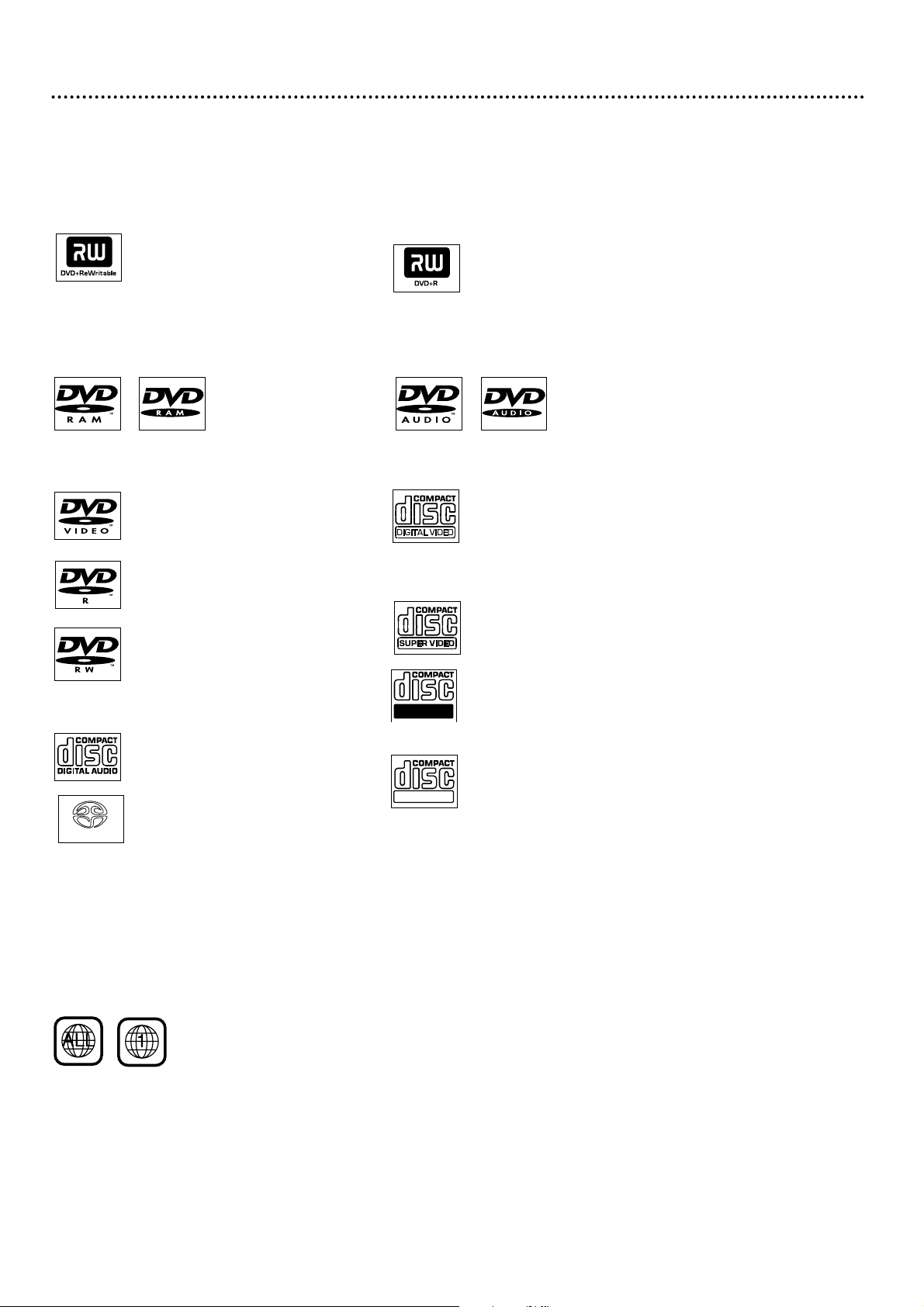
This DVD Recorder will play various types of Discs. Some Disc types will only play on the Recorder;
others will record in the Recorder; some will record and play.There are also a few types of Discs that
will neither play nor record on this Recorder. Look for these logos on your Discs to determine
whether the Disc will or will not play or record on the Philips DVD Recorder.
Playable Discs 7
Region Codes and Color Systems
DVDs must meet the requirements for Region Codes and Color Systems before you can use them
with the DVD Recorder. DVDs must be labelled for ALL regions or for Region 1 in order to play on
this DVD Recorder.You cannot play Discs that are labeled for other regions.These symbols must
appear on your DVDs, or you cannot play the DVD in this Recorder.
The number inside the globe refers to a region of the world. Region 1 represents the United States,
Canada, upper regions of North America, Bermuda, the U.S.Virgin Islands, and small regions near
Australia.
Furthermore, recordings are made according to different color systems throughout the world.The
most common color systems are NTSC, which is used primarily in the United States and North
America, PAL, and SECAM.
This Recorder is compatible with NTSC and PAL. Make sure the Discs you play were recorded in
NTSC or PAL.The color system of the DVD may appear on the DVD or on the Disc case.
However, when playing a PAL Disc, the Recorder must be connected to a PAL-compatible TV using
either the S-VIDEO (Y/C) or COMPONENT VIDEO (Y PB PR) OUT jacks of the Recorder.The
Recorder’s yellow VIDEO (CVBS) OUT jack does not send a clear PAL signal.
Discs for Playing Only
DVD (Digital Video Disc)
DVD-R (DVD-Recordable)
You cannot record on these Discs
using the Philips DVD Recorder.
DVD-RW (DVD-Rewritable)
You cannot record on these Discs
using the Philips DVD Recorder.These
Discs play only if recorded in video
mode and if finalized.
Audio CD
(Compact Disc Digital Audio)
Dual-layer Super Audio CD
(plays only the CD layer, if present)
Video CD (VCD)
Similar to DVDs, these Discs hold less
material. For example, a two-hour
movie will fit on one DVD, but may
take two VCDs.
Super Video CD (SVCD)
CD-R (CD-Recordable)
(plays only Audio CD contents)
CD-RW (CD-Rewritable)
(plays only Audio CD contents)
Discs for Recording and Playing
DVD+RW (Digital Video Disc +
Rewritable): These Discs can be
recorded on repeatedly. Recordings
can be erased, then you can record
again on the same Disc.
Discs Unsuitable for Recording
or Playing
DVD-RAM
DVD+R (Digital Video Disc +
Recordable): These Discs can be
recorded only once.After you finalize
a DVD+R, you cannot record on it
any more.
DVD-Audio
Recordable
SUPER AUDIO CD
ReWritable
Page 8
8 General Information
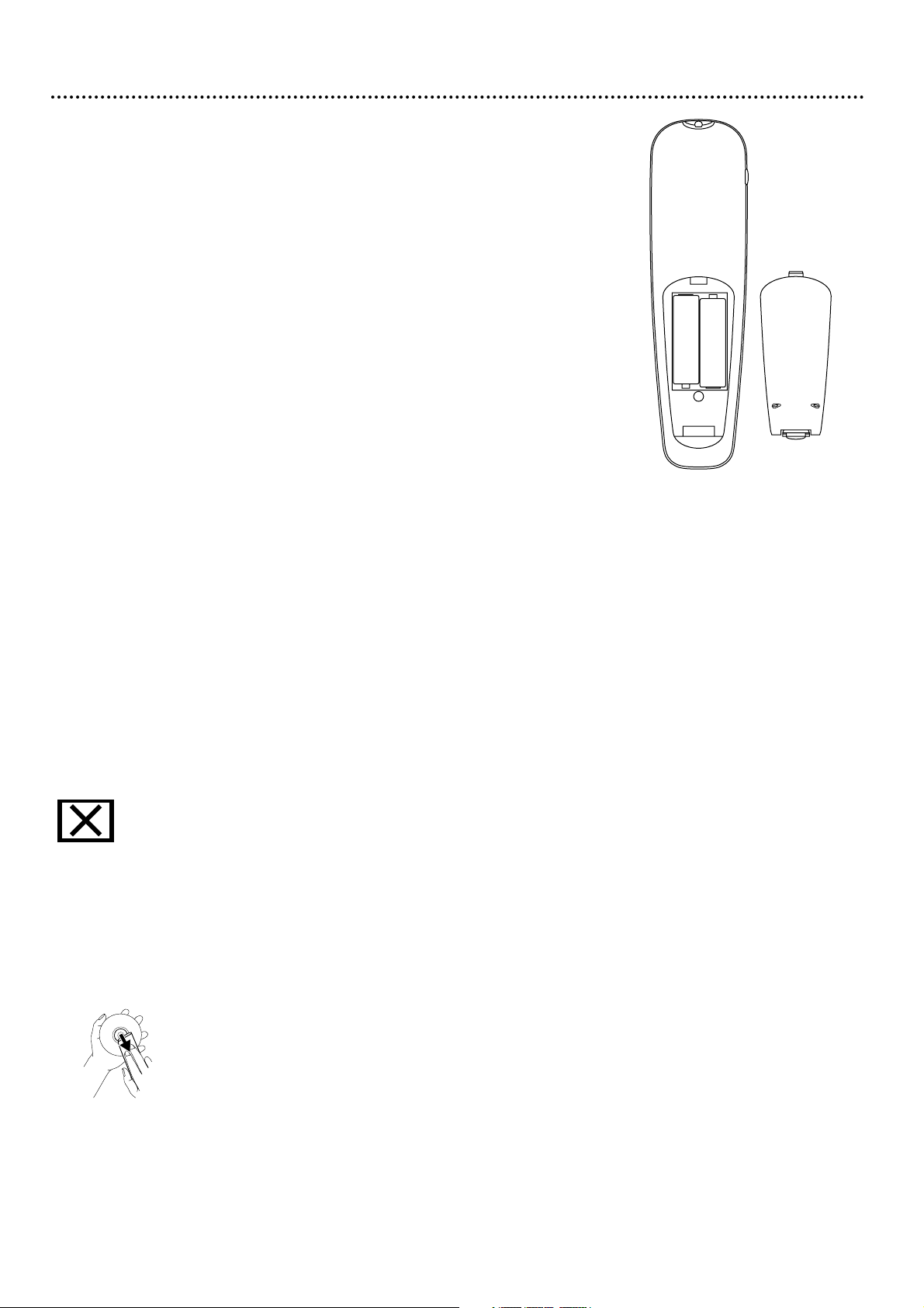
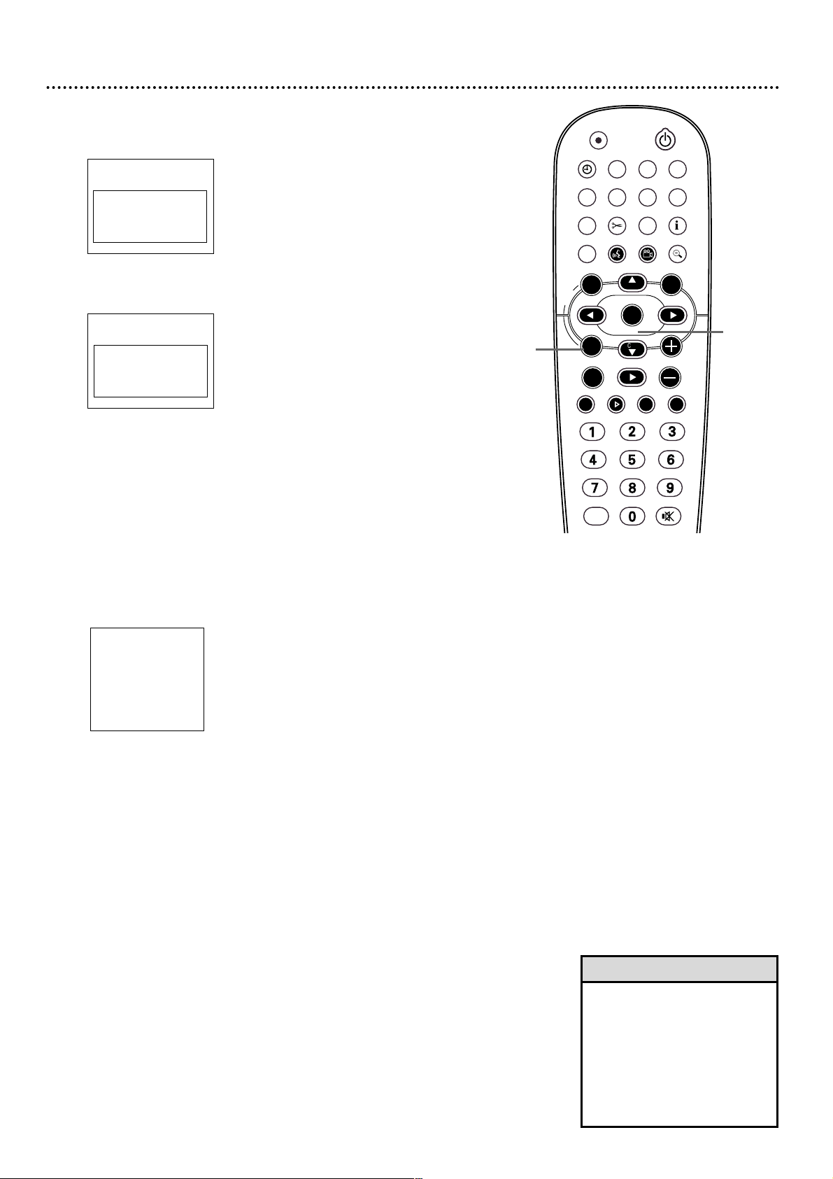
Battery Installation
1
Remove the battery compartment lid on the rear of the remote con-
trol by pressing in the tab and lifting the lid.
2
Place two AA batteries inside the battery compartment with
their +and –ends aligned as indicated. Do not mix old and new bat-
teries or different types of batteries (standard, alkaline, etc.).
3
Replace the battery compartment lid.
+
+
-
-
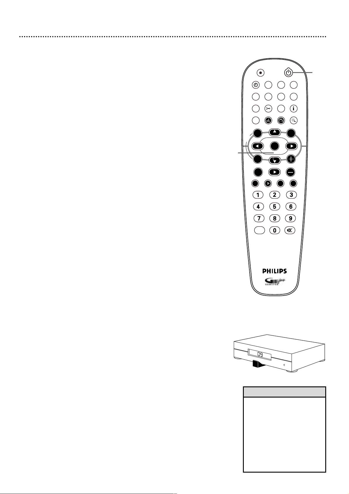
Using the Remote Control
Unless stated otherwise, the remote can operate all the features of the DVD
Recorder.Always point the remote directly at the remote sensor on the front of
the Recorder, not the TV. See page 26. Make sure there are no barriers between
the remote and the Recorder.
The Recorder’s remote will operate some features of some Philips TVs.
See page 24.
DVD Disc Menus...
Some explanations in this manual describe the DVD Disc Menus, which vary
among DVDs. Movie producers set these menus; not all DVDs have menus. If the
DVD has a menu, access it by pressing DISC MENU on the remote. See page 23.
DVD Recorder Menus...
Some instructions explain how to use the Recorder’s menu (or the System Menu
or Menu Bars) to set up features of the Recorder or the Disc.You get to the
Recorder Menu by pressing SYSTEM MENU on the remote. See page 28. Even if a
feature is set up in the Recorder’s menu, it will not be available if the current Disc
does not include that feature.
Available Disc Features...
Features described in this manual may not be available on every Disc. If
the feature is not available, you cannot use the Recorder to make the
feature available.An “X” will appear in the top left corner of the TV
screen if you try to access a feature that is not available on the current Disc. Or,
some features may not be available at the current time. For example, some features
are available only during play, while others can be accessed only if play is stopped.
Try stopping or starting play, then try the feature again.
Cleaning Discs
● When a Disc becomes dirty, clean it with a cleaning cloth.Wipe the Disc from
the center out, in a straight line. Do not wipe the Disc in a circular motion.
● Do not use solvents such as benzine, thinner, commercially available cleaners, or
anti-static spray intended for analog discs.
● Always keep the Recorder’s Disc tray closed to avoid dust on the lens.
● The lens may cloud over if you suddenly move the Recorder from cold to
warm surroundings. Playing a Disc is not possible then. Leave the power on for
about one hour with no Disc in the Recorder until normal play is possible.
Page 9

Hookups 9
Determining the best possible connection...
The capabilities of your existing equipment, especially your TV, will determine your
connection possibilities. However, the following guidelines describe which options
provide the best picture and sound quality.
★★★★ Component Video provides the best picture quality. Progressive Scan
Component Video has the ultimate quality, but use it only if the TV has
Progressive Scan. See page 12.
★★★ S-Video provides excellent picture quality. See page 13.
★★ Composite Video (a yellow Video jack) provides good picture quality. See
page 14.
★★ Your TV may have only an RF-style jack, usually labeled Antenna In or 75
ohm.You can use this connection style either with or without a Cable
Box. See pages 10-11.
★★★★ Digital audio connections provide the clearest sound. Connect one of
the DVD Recorder’s DIGITAL AUDIO OUT jacks (COAX (coaxial) or
OPTICAL) to your Stereo for the best sound quality. See page 16.
★★★ If digital audio connections are not possible, connect one pair of the
DVD Recorder’s red and white AUDIO OUT jacks to the Audio In
jacks of your Stereo or TV. See pages 12-15.
Before you begin...
● Refer to the manuals of your TV, Stereo, or other equipment as necessary.
Note the style of jacks and connectors on the other equipment. Determine
how to choose different Audio and Video In channels on your other equipment
so you can see and hear the DVD Recorder on the TV, Stereo, etc.
● Disconnect all equipment from the power outlets. Connect the equipment to
the power outlets only after you have finished hooking up everything. Never
make or change connections with equipment connected to the power outlet.
Remember...
● Set the TV to the correct Video In channel. This is channel 3 or 4 if your
TV has only the single Antenna In jack. See pages 10-11. For all other connections, find the specific Video In channel at your TV.
Video In channels may be called AUX or AUXILIARY IN, AUDIO/VIDEO or
A/V IN, EXT1 or EXT2 or External In, etc.These channels often are near TV
channel zero (0). Or, your TV remote may have a button or switch that lets
you choose the Video In channel directly. See your TV manual for details.
Or, go to your lowest TV channel and change channels down until you see the
blue Philips DVD background picture on the TV screen. (The Recorder must
be on.)
● Connect the DVD Recorder directly to the TV. For example, do not connect
the Recorder to a VCR, then connect the VCR to a TV.This type of connection
may distort the picture and sound.Also, your VCR might have the copy protection system, which could distort the DVD image.
● To connect a VCR to the DVD Recorder so you can copy videotapes
to a DVD+R or DVD+RW, see page 17.
● Set a Stereo to the correct Audio In channel or “source” mode.
● Do not connect the DVD Recorder’s AUDIO OUT jacks to the PHONO IN
jack of your Stereo.
● You only need one audio connection and one video connection between the
DVD Recorder and your TV (or TV and Stereo). So, you will not use all the
jacks on the Recorder.There are multiple jacks so you can connect to different
TV styles or to other equipment. See page 17.
● If you plan to watch your TV with the DVD Recorder off, connect the supplied
RF coaxial cable to the Recorder’s TV jack and to the RF IN or ANTENNA IN
jack (75 ohm) on your television.This lets you watch channels at the TV normally when the Recorder is off and will improve the reception at your TV.
Determine the connection that fits with your TV, then find your
choice on pages 10-16. Follow the steps for the hookup you chose.
When you finish your connections and turn on the DVD Recorder for
the first time, complete the Initial Setup.This sets up TV channels,
menu languages, and other features, including the GUIDE Plus+
®
System. See pages 18-20 to do the Initial Setup.
Page 10
10 Hookups (cont’d)
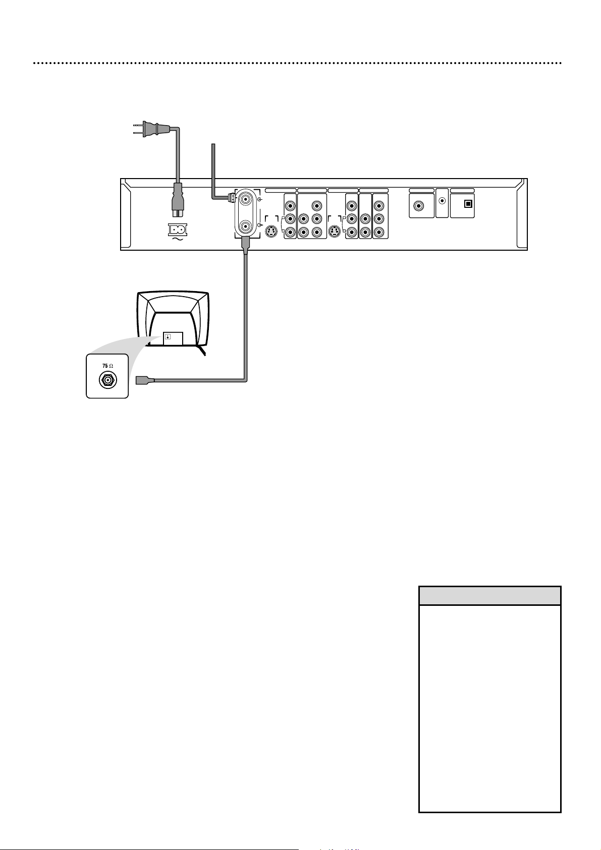
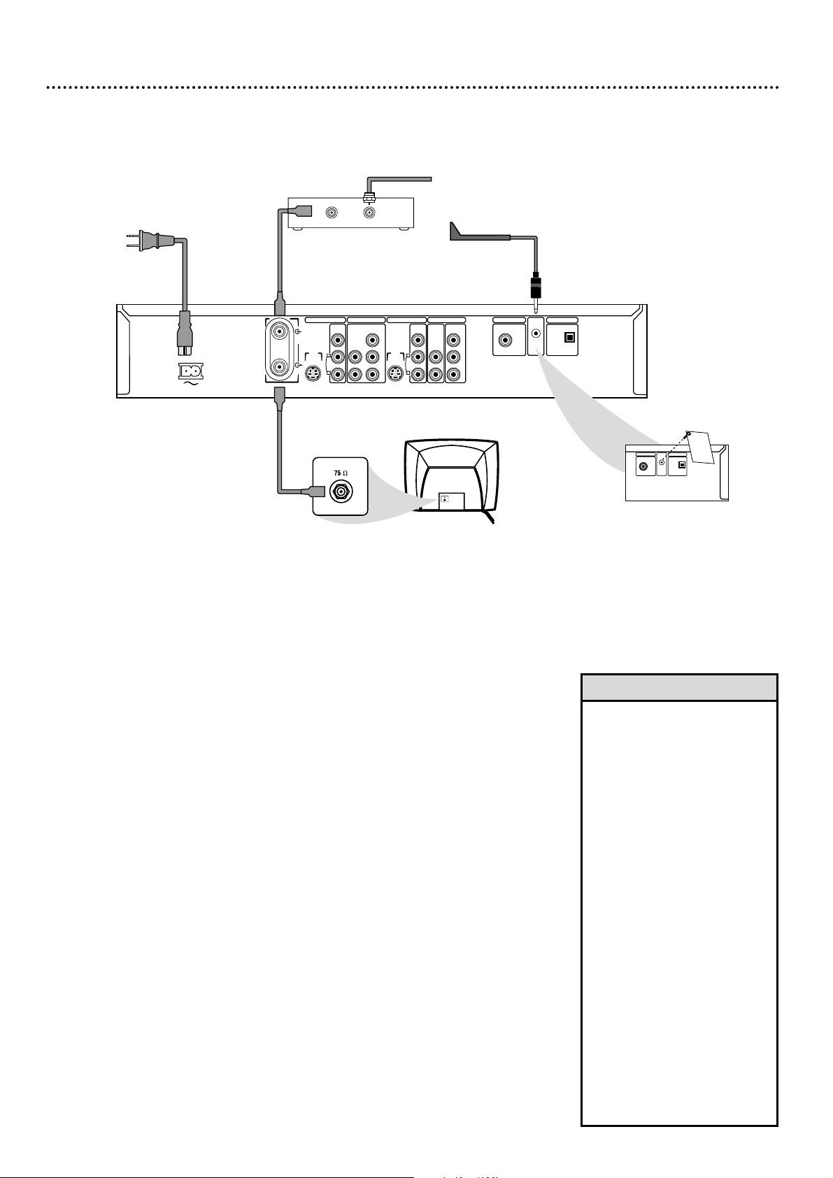
Connecting to a TV Only
TV has only an Antenna In jack
1
Connect your Antenna or Cable TV signal to the ANTENNA jack on
the rear of the Recorder. Your antenna or Cable TV signal may have been
connected to your TV already. If so, disconnect it from the TV and connect it
to the Recorder’s ANTENNA jack.
2
Connect the supplied RF coaxial cable to the TV jack on the rear of
the Recorder. Connect the other end of the same RF coaxial cable
to the Antenna In jack on your TV. Your TV’s Antenna In jack may be
labelled RF In,Antenna In, or 75 ohm. Check your TV’s manual for details.
3
Connect the supplied power cord to the MAINS ~ (AC Power) jack
on the rear of the Recorder.
Connect the power cords of the Recorder and the TV to a power
outlet.
4
Press STANDBY-ON yyon the front of the Recorder to turn it on.
“IS TV ON? CH03” will appear on the Recorder’s display panel the first time
you turn on the Recorder.
5
Turn on the TV. Set it to channel 3. You should see the blue Philips DVD
background picture or the Initial Setup screen.Initial Setup appears the first time
you turn on the Recorder. Go to pages 18-20 to complete the Initial Setup.
• The Recorder’s display may
show “IS TV ON? C04” instead.
If so, put the TV on channel 4.
• If you need to use TV channel 4
but “IS TV ON? C03” appears
on the display, press and hold
the Number 4 button on the
Recorder’s remote. After several
seconds, the display will change
to “IS TV ON? C04.” Set your
TV to channel 4.
Likewise, if the display shows “IS
TV ON? C04” and you need TV
channel 3, press and hold the
Number 3 button.
Use this procedure while the
Recorder is on and “IS TV
ON?...” shows on the display.
Helpful Hints
S-VIDEO
(Y/C)
ANTENNA
TV
S-VIDEO
(Y/C)
VIDEO
(CVBS)
VIDEO
(CVBS)
COMPONENT
VIDEO
AUDIO
COMPONENT
VIDEO
AUDIO
Y
P
B
P
R
Y
P
B
P
R
IN - EXT 2 IN - EXT 1
OUT 2 OUT 1
480p/480
i
COAX OUT
G-LINK
DIGITAL AUDIO OUT
OPTICAL OUT
MAINS
AUDIO
L
R
AUDIO
L
R
Antenna or
Cable TV
Signal
Back of TV
(example only)
DIGITAL AUDIO OUT
Page 11
Hookups (cont’d) 11
Connecting to a TV and a Cable Box or Satellite Receiver
This example shows a Cable Box, but the steps are the same for a Satellite
Receiver. Do not use the G-Link cable if you have a Satellite Receiver.
1
Connect your Cable TV signal to the ANTENNA IN jack on your
Cable Box.
2
If your Cable Box has an ANTENNA OUT or TO TV jack, connect
an RF coaxial cable to it and to the Recorder’s ANTENNA jack.
If your Cable Box has red, white, and yellow AUDIO and VIDEO OUT jacks, use the
supplied audio and video cables to connect those jacks to the Recorder’s IN EXT 2
VIDEO (CVBS) and AUDIO L/R jacks instead.
3
Connect an RF coaxial cable to the Recorder’s TV jack and to the
ANTENNA IN or RF IN jack on your TV. Your TV’s Antenna In jack may
be labelled RF In or 75 ohm. Check your TV manual for details.
4
Connect the supplied power cord to the MAINS ~ (AC Power) jack
on the rear of the Recorder. Connect the power cords of the
Recorder, Cable Box/Satellite Receiver, and TV to a power outlet.
5
If you have a Cable Box, remove the Demo Pin from the Recorder’s G-
LINK jack. (This should have been in place when you bought the Recorder.)
Connect the supplied G-Link cable to the G-LINK jack now.You will
need this later to use the GUIDE Plus+
®
System.
6
Press STANDBY/ON yyto turn on the Recorder. Set the Recorder
to channel 3 or 4 (your Cable Box output channel) if you used an RF coaxi-
al cable at step 2. Or, set the Recorder to EXT 2 if you connected the Cable
Box to those jacks at step 2.
7
“IS TV ON? CH03” will appear on the Recorder’s display panel the first time
you turn it on. Turn on the TV and the Cable Box. Set the TV to chan-
nel 3 to receive the picture from the Recorder.
You should see the blue Philips DVD background picture or the Initial Setup
screen. Initial Setup appears the first time you turn on the Recorder. Go to pages
18-20 to complete the Initial Setup.
OUT IN
Cable TV Signal
Cable Box
S-VIDEO
(Y/C)
ANTENNA
TV
S-VIDEO
(Y/C)
VIDEO
(CVBS)
VIDEO
(CVBS)
COMPONENT
VIDEO
AUDIO
COMPONENT
VIDEO
AUDIO
Y
P
B
P
R
Y
P
B
P
R
IN - EXT 2 IN - EXT 1
OUT 2 OUT 1
480p/480
i
COAX OUT
G-LINK
DIGITAL AUDIO OUT
OPTICAL OUT
MAINS
AUDIO
L
R
AUDIO
L
R
Back of TV
(example only)
DIGITAL AUDIO OUT
To front of Cable Box
COAX OUT
G-LINK
DIGITAL AUDIO OUT
OPTICAL OUT
D
E
M
O
P
I
N
T
h
i
s
D
e
m
o
P
i
n
a
c
t
i
v
a
t
e
s
a
n
a
u
t
o
m
a
t
i
c
G
U
I
D
E
P
l
u
s
+
d
e
m
o
.
R
E
T
A
I
L
E
R
S
D
o
n
o
t
r
e
m
o
v
e
t
h
i
s
D
e
m
o
P
i
n
.
R
e
m
o
v
a
l
w
i
l
l
d
i
s
a
b
l
e
t
h
e
a
u
t
o
-
m
a
t
i
c
d
e
m
o
.
C
O
N
S
U
M
E
R
S
R
e
m
o
v
e
t
h
i
s
D
e
m
o
P
i
n
a
n
d
i
n
s
e
r
t
t
h
e
I
R
e
x
t
e
n
d
e
r
h
e
r
e
b
e
f
o
r
e
u
s
i
n
g
t
h
i
s
T
V
.
W
A
R
N
I
N
G
D
i
s
p
o
s
e
o
f
p
r
o
p
e
r
l
y
.
K
E
E
P
A
W
A
Y
F
R
O
M
C
H
I
L
D
R
E
N
DIGITAL AUDIO OUT
• To watch TV, put the Recorder in
Monitor mode and on channel 3
or 4. (Press MONITOR on the
Recorder’s remote.) Change TV
channels at your Cable Box.
• The Recorder’s display may show
“IS TV ON? C04” instead. If so,
put the TV on channel 4.
• If you need to use TV channel 4
but “IS TV ON? C03” appears on
the display, press and hold the
Number 4 button on the
Recorder’s remote. After several
seconds, the display will change
to “IS TV ON? C04.” Set your TV
to channel 4.
Likewise, if the display shows “IS
TV ON? C04” and you need TV
channel 3, press and hold
Number 3. Use this procedure
while the Recorder is on and “IS
TV ON?...” shows on the display.
• You can use the connections
between the Recorder and a
TV/Stereo shown on pages 1216 instead. You will choose a different Video In channel at the TV.
Helpful Hints
Page 12
12 Hookups (cont’d)
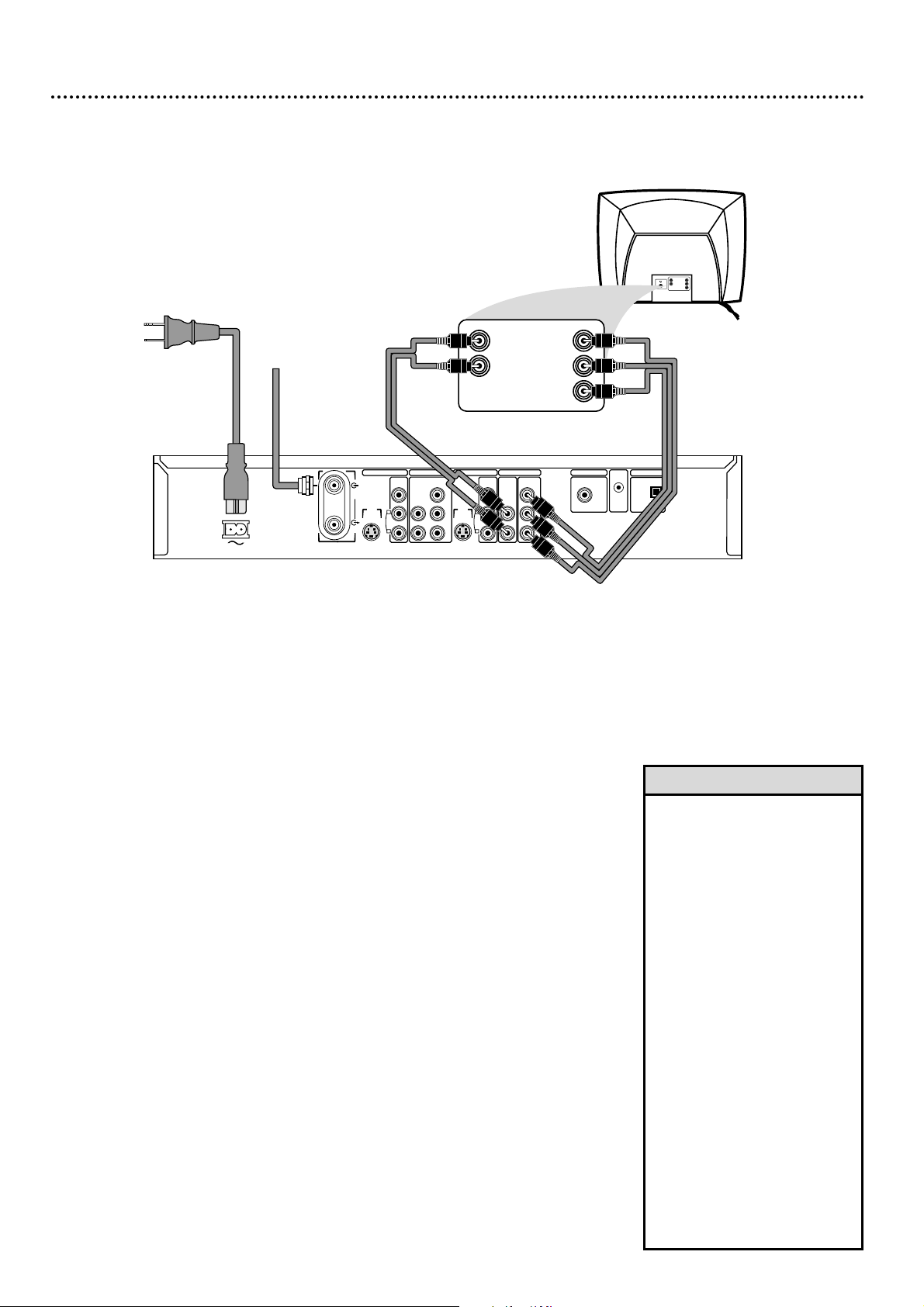
Connecting to a TV Only
TV has Component Video In Jacks
Back of TV
(example only)
Pr/Cr
Pb/Cb
Y
RIGHT AUDIO IN
LEFT AUDIO IN
LEFT AUDIO IN
RIGHT AUDIO IN
Cr/R-Y
Y
Cb/B-Y
S-VIDEO
(Y/C)
ANTENNA
TV
S-VIDEO
(Y/C)
VIDEO
(CVBS)
VIDEO
(CVBS)
COMPONENT
VIDEO
AUDIO
COMPONENT
VIDEO
AUDIO
Y
P
B
P
R
Y
P
B
P
R
IN - EXT 2 IN - EXT 1
OUT 2 OUT 1
480p/480
i
COAX OUT
G-LINK
DIGITAL AUDIO OUT
OPTICAL OUT
MAINS
AUDIO
L
R
AUDIO
L
R
Antenna
or Cable TV
Signal
DIGITAL AUDIO OUT
1
Connect your Antenna or Cable TV signal to the ANTENNA jack on
the rear of the Recorder.
2
Connect the Recorder’s OUT 1 COMPONENT VIDEO Y PB PR
jacks to the COMPONENT VIDEO IN jacks on the TV. Use the sup-
plied three-strand component video cable, which has red, blue, and green
markings. Match the cable colors to the jack colors.
3
Connect the Recorder’s OUT 1 AUDIO L/R (left/right) jacks to the
left/right AUDIO IN jacks on the TV. Use the supplied two-strand audio
cable, which has red and white markings. Match the cable colors to the jack
colors.
4
Connect the supplied power cord to the MAINS ~ (AC Power) jack
on the rear of the Recorder.
Connect the power cords of the Recorder and the TV to a power
outlet.
5
Press STANDBY-ON yyon the front of the Recorder to turn it on.
“IS TV ON? CH03” will appear on the Recorder’s display panel the first time
you turn on the Recorder.
6
Turn on the TV. Set it to the Component Video In channel, not chan-
nel 3 or 4. (See your TV manual for details. Or, go to your lowest TV channel
and change channels down until you see the DVD background picture or
Initial Setup screens.) Initial Setup will appear the first time you turn on the
Recorder. Go to pages 18-20 to complete Initial Setup.
•
If your TV has Progressive Scan
(Pro Scan), connect the
Recorder’s OUT 1 COMPONENT VIDEO Y P
B PR jacks to
the TV’s Progressive Scan In jacks
instead. Pro Scan doubles the
number of visible picture lines
per field, providing a jitter-free,
sharp, quiet picture. See your TV
manual for details. If you use Pro
Scan, set the Recorder’s Video
Output to Progressive Scan. See
page 58.
• On the TV, the Component Video
In jacks may be labeled YUV or
Pr/Cr Pb/Cb Y and may be green,
blue, and red.
• To watch TV with the Recorder
off, connect the RF coaxial cable
to the Recorder’s TV jack and to
the RF IN or ANTENNA IN jack
(75 ohm) on your TV. This lets
you watch channels at the TV
when the Recorder is off and will
improve TV reception. See page
10 for this hookup.
Helpful Hints
Page 13
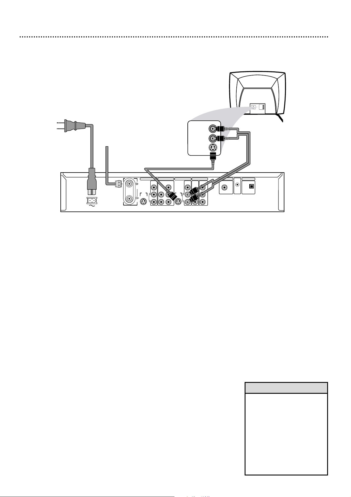
1
Connect your Antenna or Cable TV signal to the ANTENNA jack on
the rear of the Recorder.
2
Connect an S-Video cable (not supplied) to the OUT 2 S-VIDEO
(Y/C) jack of the Recorder and to the TV’s S-VIDEO In jack.
3
Connect the supplied audio cable to the Recorder’s OUT 2 AUDIO
L/R (left/right) jacks and to the left/right AUDIO IN jacks on the TV.
Audio cables have red and white markings. Match cable colors to jack colors.
4
Connect the supplied power cord to the MAINS ~ (AC Power) jack
on the rear of the Recorder.
Connect the power cords of the Recorder and the TV to a power
outlet.
5
Press STANDBY-ON yyon the front of the Recorder to turn it on.
“IS TV ON? CH03” will appear on the Recorder’s display panel the first time
you turn it on.
6
Turn on the TV. Set it to the S-Video In channel, not channel 3 or 4.
(See your TV manual for details. Or, go to your lowest TV channel and change
channels down until you see the DVD background picture or Initial Setup
screens.) Initial Setup will appear the first time you turn on the Recorder. Go to
pages 18-20 to complete Initial Setup.
Hookups (cont’d) 13
Connecting to a TV Only
TV has an S-Video In Jack
S-VIDEO
(Y/C)
ANTENNA
TV
S-VIDEO
(Y/C)
VIDEO
(CVBS)
VIDEO
(CVBS)
COMPONENT
VIDEO
AUDIO
COMPONENT
VIDEO
AUDIO
Y
P
B
P
R
Y
P
B
P
R
IN - EXT 2 IN - EXT 1
OUT 2 OUT 1
480p/480
i
COAX OUT
G-LINK
DIGITAL AUDIO OUT
OPTICAL OUT
MAINS
AUDIO
L
R
AUDIO
L
R
LEFT AUDIO IN
RIGHT AUDIO IN
VIDEO IN
LEFT AUDIO IN
RIGHT AUDIO IN
Antenna
or Cable TV
Signal
DIGITAL AUDIO OUT
S-VIDEO IN
• On the TV, the S-Video In jack
may be labeled Y/C, S-Video, or
S-VHS (super video).
• To watch TV with the Recorder
off, connect the RF coaxial cable
to the Recorder’s TV jack and to
the RF IN or ANTENNA IN
jack (75 ohm) on your TV. This
lets you watch channels at the
TV when the Recorder is off
and will improve TV reception.
See page 10 for this hookup.
Helpful Hints
Page 14
14 Hookups (cont’d)
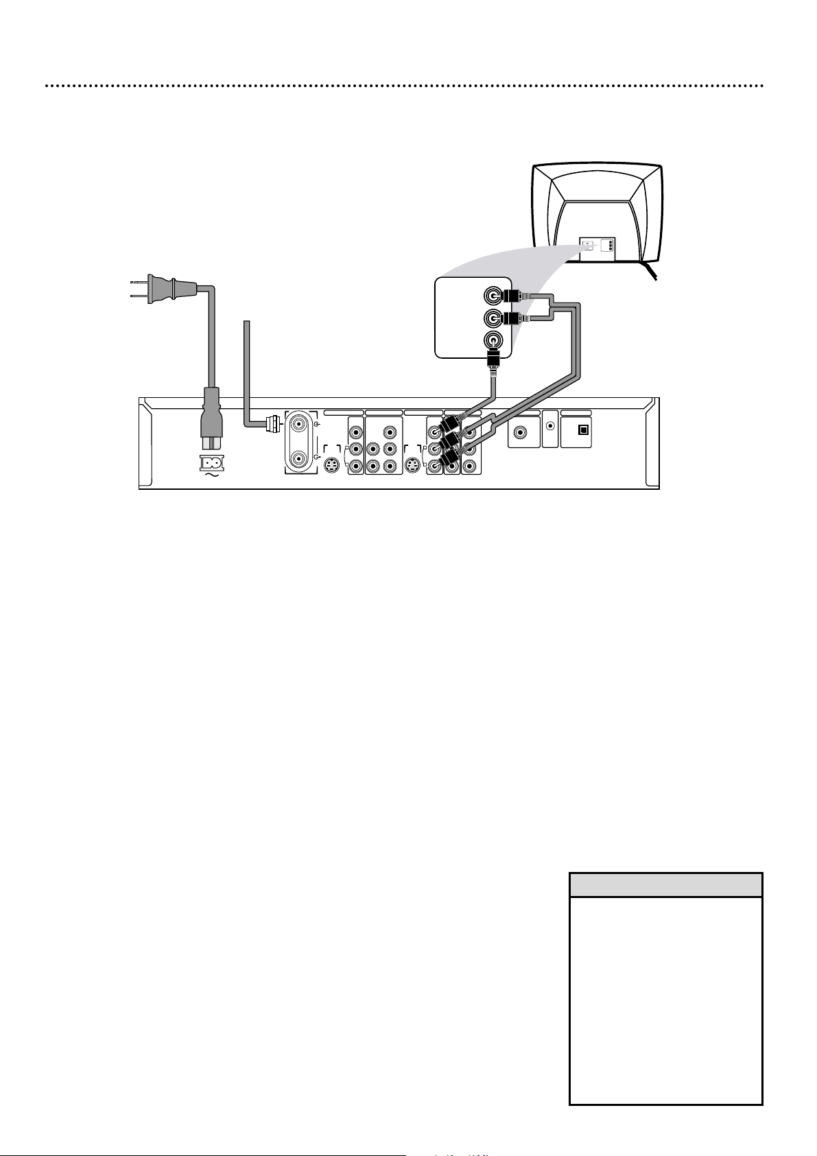
Connecting to a TV Only
TV has a yellow CVBS Video In jack
S-VIDEO
(Y/C)
ANTENNA
TV
S-VIDEO
(Y/C)
VIDEO
(CVBS)
VIDEO
(CVBS)
COMPONENT
VIDEO
AUDIO
COMPONENT
VIDEO
AUDIO
Y
P
B
P
R
Y
P
B
P
R
IN - EXT 2 IN - EXT 1
OUT 2 OUT 1
480p/480
i
COAX OUT
G-LINK
DIGITAL AUDIO OUT
OPTICAL OUT
MAINS
AUDIO
L
R
AUDIO
L
R
LEFT AUDIO IN
RIGHT AUDIO IN
VIDEO IN
LEFT AUDIO IN
RIGHT AUDIO IN
VIDEO IN
Antenna
or Cable TV
Signal
DIGITAL AUDIO OUT
1
Connect your Antenna or Cable TV signal to the ANTENNA jack on
the rear of the Recorder.
2
Connect the Recorder’s yellow OUT 2 VIDEO (CVBS) jack to the
VIDEO IN jack on your TV. The supplied video cable has yellow markings.
3
Connect the supplied audio cables to the Recorder’s OUT 2 AUDIO
L/R (left/right) jacks and to the left/right AUDIO IN jacks on the TV.
Audio cables have red and white markings. Match cable colors to jack colors.
4
Connect the supplied power cord to the MAINS ~ (AC Power) jack
on the rear of the Recorder. Connect the power cords of the
Recorder and the TV to a power outlet.
5
Press STANDBY-ON yyon the front of the Recorder to turn it on.
“IS TV ON? CH03” will appear on the Recorder’s display panel the first time
you turn on the Recorder.
6
Turn on the TV. Set the TV to its Audio/Video In channel. It may be
called AUX or AUXILIARY IN, AUDIO/VIDEO or A/V IN, EXT1 or EXT2
or External In, etc. Or, your TV remote may have a button or switch that
selects the Video In channel.
This is not channel 3 or 4. See your TV manual
for details. Or, go to your lowest TV channel and change channels down until
you see the DVD background picture or Initial Setup.
Initial Setup will appear the first time you turn on the Recorder. Go to pages 18-20
to complete Initial Setup.
• On the TV, the Video In jack is
usually yellow and might be
labeled video, CVBS, composite,
or baseband.
• To watch TV with the Recorder
off, connect the RF coaxial cable
to the Recorder’s TV jack and to
the RF IN or ANTENNA IN
jack (75 ohm) on your TV. This
lets you watch channels at the
TV when the Recorder is off
and will improve TV reception.
See page 10 for this hookup.
Helpful Hints
Page 15
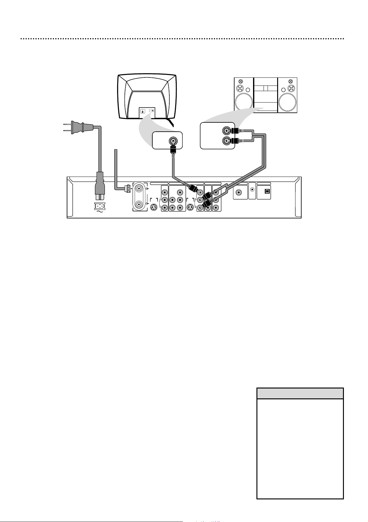
Hookups (cont’d) 15
Connecting to a TV
and a Stereo with red/white Audio In jacks)
S-VIDEO
(Y/C)
ANTENNA
TV
S-VIDEO
(Y/C)
VIDEO
(CVBS)
VIDEO
(CVBS)
COMPONENT
VIDEO
AUDIO
COMPONENT
VIDEO
AUDIO
Y
P
B
P
R
Y
P
B
P
R
IN - EXT 2 IN - EXT 1
OUT 2 OUT 1
480p/480
i
COAX OUT
G-LINK
DIGITAL AUDIO OUT
OPTICAL OUT
MAINS
AUDIO
L
R
AUDIO
L
R
Back of TV
(example only)
S-AUDIO IN
Stereo
(example only)
Antenna
or Cable TV
Signal
LEFT AUDIO IN
RIGHT AUDIO IN
DIGITAL AUDIO OUT
VIDEO IN
1
Connect your Antenna or Cable TV signal to the ANTENNA jack on
the rear of the Recorder.
2
Connect the Recorder’s yellow OUT 2 VIDEO (CVBS) jack to the
VIDEO IN jack on your TV. The supplied video cable has yellow markings.
3
Connect audio cables to the Recorder’s OUT 2 AUDIO L/R
(left/right) jacks and to the left/right AUDIO IN jacks on the Stereo.
Audio cables have red and white markings. Match cable colors to jack colors.
4
Connect the supplied power cord to the MAINS ~ (AC Power) jack
on the rear of the Recorder. Connect the power cords of the
Recorder, Stereo, and TV to a power outlet.
5
Turn on the Stereo and select the correct Audio In channel or
sound source. Refer to the Stereo manual.
6
Press STANDBY-ON yyon the front of the Recorder to turn it on.
“IS TV ON? CH03” will appear on its display the first time you turn it on.
7
Turn on the TV and select its Audio/Video In channel. It may be called
AUX or AUXILIARY IN,AUDIO/VIDEO or A/V IN,EXT1 or EXT2 or
External In, etc. Or, your TV remote may have a button or switch that
selects the Video In channel.
This is not channel 3 or 4. See your TV manual
for details. Or, go to your lowest TV channel and change channels down until
you see the DVD background picture or Initial Setup.
Initial Setup will appear the first time you turn on the Recorder. Go to pages 18-20
to complete Initial Setup.
• Set Analog output. See page 59.
• You may use Component Video
or S-Video at step 2 instead for
higher picture quality. See pages
12-13.
• To watch TV with the Recorder
off, connect the RF coaxial cable
to the Recorder’s TV jack and to
the RF IN or ANTENNA IN
jack (75 ohm) on your TV. This
lets you watch channels at the
TV when the Recorder is off
and will improve TV reception.
See page 10 for this hookup.
Helpful Hints
Page 16
16 Hookups (cont’d)
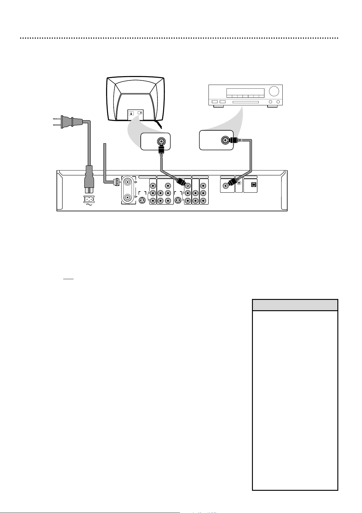
Connecting to a TV and a Digital Stereo
(Stereo has Dolby Digital
TM
, MPEG2, or Digital Theater System)
S-VIDEO
(Y/C)
ANTENNA
TV
S-VIDEO
(Y/C)
VIDEO
(CVBS)
VIDEO
(CVBS)
COMPONENT
VIDEO
AUDIO
COMPONENT
VIDEO
AUDIO
Y
P
B
P
R
Y
P
B
P
R
IN - EXT 2 IN - EXT 1
OUT 2 OUT 1
480p/480
i
COAX OUT
G-LINK
DIGITAL AUDIO OUT
OPTICAL OUT
MAINS
AUDIO
L
R
AUDIO
L
R
Back of TV
(example only)
COAXIAL DIGITAL
AUDIO IN
S-AUDIO IN
Stereo
(example only)
Antenna
or Cable TV
Signal
DIGITAL AUDIO OUT
VIDEO IN
1
Connect your Antenna or Cable TV signal to the ANTENNA jack on
the rear of the Recorder.
2
Connect one of the Recorder’s DIGITAL AUDIO OUT jacks -
COAX (coaxial) OUT or OPTICAL OUT - to a DIGITAL AUDIO
IN jack on your Stereo. You only need one connection, depending on what
your Stereo has. Use an appropriate digital audio cable (not supplied).
3
Connect the Recorder’s yellow OUT 2 VIDEO (CVBS) jack to the
VIDEO IN jack on your TV. The supplied video cable has yellow markings.
4
Connect the supplied power cord to the MAINS ~ (AC Power) jack
on the rear of the Recorder. Connect the power cords of the
Recorder, Stereo, and TV to a power outlet.
5
Turn on the Stereo and select its Digital Audio In channel or sound
source. Refer to the Stereo manual.
6
Press STANDBY-ON yyon the front of the Recorder to turn it on.
“IS TV ON? CH03” will appear on the Recorder’s display panel the first time
you turn on the Recorder.
7
Turn on the TV and choose its Video In channel. It may be called AUX
or AUXILIARY IN, AUDIO/VIDEO or A/V IN, EXT1 or EXT2 or External
In, etc. Or, your TV remote may have a button or switch that selects the
Video In channel.
This is not channel 3 or 4. See your TV manual for details.
Or, go to your lowest TV channel and change channels down until you see the
DVD background picture or Initial Setup.
Initial Setup will appear the first time you turn on the Recorder. Go to pages 18-20
to complete Initial Setup.
• Set Digital output. See page 59.
Otherwise the Stereo may pro-
duce a strong, distorted sound
or no sound at all.
• Your Stereo must support
MPEG2, Dolby Digital
TM
or
Digital Theater System (DTS).
Check your Stereo manual.
• You may use Component Video
or S-Video at step 3 instead for
higher picture quality. See pages
12-13.
• A small, square, black cap protects the OPTICAL OUT jack.
Remove the cap to use the
jack; replace it when the jack is
not in use.
• To watch TV with the Recorder
off, connect the RF coaxial cable
to the Recorder’s TV jack and to
the RF IN or ANTENNA IN
jack (75 ohm) on your TV. This
lets you watch channels at the
TV when the Recorder is off
and will improve TV reception.
See page 10 for this hookup.
Helpful Hints
Page 17
Hookups (cont’d) 17
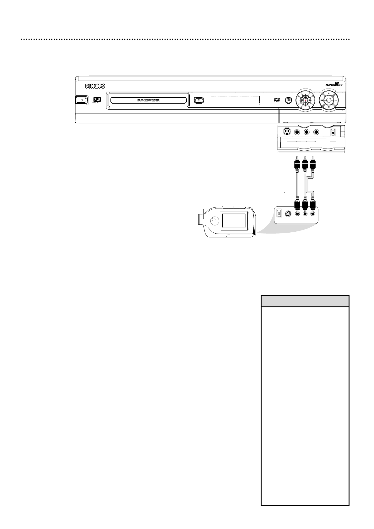
Connecting to Other Equipment
Dubbing Videotape to a DVD+R/DVD+RW
S-VIDEO
VIDEO AUDIO
LEFT RIGHT
DV
GUIDE
OPEN
STANDBY-ON
DVDR 80
OPEN/CLOSE
U
P
L
E
F
T
R
I
G
H
T
D
O
W
N
S-VIDEO
VIDEO
AUDIO
L
R
DV IN
CAM 2
CAM 1
• Use the DV IN CAM 2 jack to
connect the Recorder to a
Personal Computer that has a
Digital Video output.The PC
must have an IEEE 1394
Firewire connector. Limited PC
applications may be supported.
You also can use this jack to
connect the Recorder to Digital
Video or Hi-8 camcorders. If
you use the DV IN CAM 2 jack,
choose CAM 2 at the Recorder
in Monitor mode to see the
material playing on other equipment.
• Most prerecorded videotapes
and DVDs are copy protected. If
you try to copy them, the
Recorder display may show
“COPY PROTECT.”
• If the Recorder’s display shows
“NO SIGNAL,” adjust the tracking or play the tape at the
VCR/Camcorder.
• Do not connect a Progressive
Scan video source (such as a
DVD Player) to the IN EXT 1
COMPONENT VIDEO jacks. The
Recorder cannot receive
Progressive Scan video.
Helpful Hints
You can connect a Video Cassette Recorder
(VCR), Camcorder, or DVD Player to the
Recorder’s CAM or IN-EXT jacks.
A sample connection with a Camcorder is shown
here, using the CAM 1 AUDIO/VIDEO IN jacks
on the front of the Recorder. These jacks are the
most easily accessible. Other equipment will connect similarly, but this is a common connection
possibility.
You will need this connection to copy
videotapes onto a DVD+R or DVD+RW.
There are more Component Video, S-Video,
Digital Video, and Audio In jacks on the front and
rear of the Recorder. If your other equipment
has these jacks, use them instead. Use the IN-EXT
jacks on the rear of the Recorder for permanent
connections.That will hide the cables from view.
1
Connect the DVD Recorder directly to your TV.
Choose a connection from pages 10-16.
2
To access the jacks on the front of the Recorder, flip down the
door that covers the jacks. Press where the door is marked OPEN :.
3
Connect a video cable to the VIDEO OUT jack of your
Camcorder and to the yellow CAM 1 VIDEO IN jack on the front
of the DVD Recorder. Use an RCA-style video cable, which is usually
marked with yellow. (One video cable is supplied with the Recorder.)
4
Connect audio cables to the AUDIO OUT jacks of your
Camcorder and to the red and white CAM 1 AUDIO IN jacks on
the front of the DVD Recorder. Most audio cables are marked with
red and white. Match the cable colors to the jack colors. (One pair of audio
cables is supplied with the DVD Recorder.)
5
When all connections are complete, connect all the equipment to
power. Turn on all the equipment. Press STANDBY-ON y on the
front of the DVD Recorder to turn it on.
6
Set your TV to the correct Video In channel. This will be channel 3
or 4 or a specific Video In channel, depending on your connection between
the Recorder and the TV. Refer to the connection details on pages 9-16.
Or, simply go to channel 5 on your TV, then change channels down until
you see the DVD Recorder’s logo. Initial Setup will appear the first time you
turn on the Recorder. See pages 18-20 to do Initial Setup first.
7
To watch or record the material playing on the other equipment, press
MONITOR to put the Recorder in Monitor mode. Press CH+8 or
CH-9 to select CAM1 at the Recorder. This is located after your
highest TV channel and before your lowest TV channel. Choose CAM1 if
you used the connection shown on this page (with the jacks on the front of
the Recorder). If you use the IN EXT 1 or IN EXT 2 jacks on the rear of
the Recorder instead, choose channel EXT 1 or EXT 2. Choose the channel that matches the jacks to which you connected the other equipment.
Start playing the material by pressing PLAY on the other equipment. Press Record I on the front of the DVD Recorder to start
recording. See page 21.
Page 18
18 Initial Setup
Initial Setup menus will appear on the TV the first time you turn on the
Recorder. These help you set up TV channels, the GUIDE Plus+
®
System, and
other features for the first time.
During Initial Setup,“IS TV ON?” will appear on the Recorder’s dis-
play panel. Turn on your TV and set it to channel 3 or 4 OR the correct Video In channel.Your TV must be on the correct Video In
channel to see the Initial Setup menus. See pages 9-17 to find the Video
In channel for your hookup.Or, check your TV manual for details.
You cannot open the Disc tray while “IS TV ON?” appears.“INSTALL
RECORDER FIRST” will show on the display panel.
You cannot turn off the Recorder until you finish the Initial Setup.
The only way to quit the Initial Setup is to disconnect the power
cord. If you quit, the Initial Setup screens will appear again the next
time you turn on the Recorder.The screens will not go away until
you finish the Initial Setup.
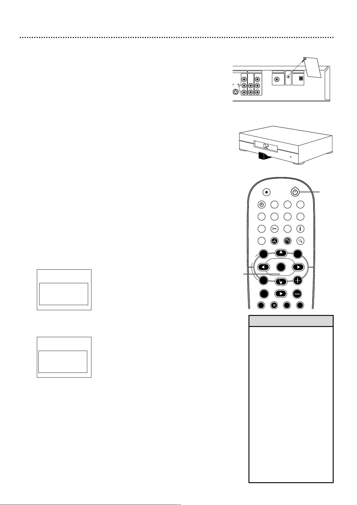
1
Remove the Demo Pin from the G-LINK jack on the rear of
the Recorder. Otherwise, a GUIDE Plus+®System demonstration
will run after you finish Initial Setup.
2
If you are using a Cable Box, connect the G-Link cable to
the Recorder’s G-LINK jack. See page 11. Place the G-Link
sensor in front of your Cable Box. Turn on the Cable Box and
set it to channel 2.
3
Press STANDBYyyto turn on the Recorder. PHILIPS will show
on the display panel. It will take the Recorder several seconds to
turn on.
4
The Menu Language screen will appear first. Press 8CH+ or
9CH- to choose English, Espanol, or Francais. Press OK.
The Recorder’s menus will be in the language you selected.
To change the Menu Language later, see page 60.
5
The Audio Language menu appears next. Press 8CH+ or 9CH-
to choose the language you prefer, then press OK.
To change the Audio Language later, see pages 48 and 60.
~
Initial Setup
Menu Language
English
K
L
Español
Français
Press OK to continue
~
Initial Setup
Audio Language
English
K
L
Español
Français
Português
Italiano
Press OK to continue
• The Recorder’s features will scroll
across the display panel when
you first connect the power cord.
This is a demonstration that cannot be cancelled.
• The Initial Setup screens will disappear after about 20 minutes
of inactivity.The Recorder will
turn off. The Initial Setup menus
will reappear when you turn on
the Recorder again.
• If the Initial Setup menus don’t
appear, your Recorder is set
already.To change items later, see
the pages for each feature.
• You can use channel 3 or 4 at
your TV. While “IS TV ON? C04”
is on the Recorder’s display, press
and hold the remote’s Number 3
button until the display shows “IS
TV ON? C03.” Set your TV to
channel 3.To change to channel
4, press and hold Number 4
instead during this process.
Helpful Hints
STANDBY
REC/OTR
TIMER REC MODE PLAY MODE TV/DVD
MONITOR
•TV
DIM RETURN T/C
DISC MANAGER FSS SELECT
SUBTITLE
STOP TV VOLUME
PAUSESLOW
PLAY
AUDIO ANGLE ZOOM
GUIDE/TV
`
i
CHCH
-
CHCH
+
OK
SYSTEM
DISCDISC
Ç
H Gk
MENU
4-5
3
C
A
B
L
E
B
O
X
C
A
B
L
E
B
O
X
Instructions continue on the next page.
S-VIDEO
(Y/C)
VIDEO
(CVBS)
COMPONENT
VIDEO
AUDIO
Y
P
B
P
R
OUT 2 OUT 1
480p/480
i
COAX OUT
G-LINK
DIGITAL AUDIO OUT
OPTICAL OUT
AUDIO
L
R
D
E
M
O
P
I
N
This De
m
o Pin ac
tivates an
a
utom
atic
G
UI
DE
Plus+
d
em
o.
R
ET
AILE
RS
D
o
not
remov
e this D
em
o P
in.
R
em
ov
al w
ill disable the auto
-
matic d
em
o.
C
ON
SU
M
ER
S
Rem
ove this
D
emo
Pin and
i
ns
ert
the I
R
extender
here
before using this TV
.
W
AR
NING
Di
spose o
f properly.
K
EE
P
AW
A
Y
FR
OM
CH
ILD
R
EN
DIGITAL AUDIO OUT
1
2
Page 19
Initial Setup (cont’d) 19
6
The Subtitle Language menu appears next. Press 8CH+ or 9CH-
to choose a language for subtitles, then press OK.
To change the Subtitle Language later, see pages 48 and 60.
7
The TV Shape menu appears next. Press 8CH+ or 9CH- to
choose the preferred TV Shape, then press OK.
To change the TV Shape later or for details on TV Shapes, see page 58.
8
“If you have connected the antenna - press OK” appears next. If
you have connected an Antenna or Cable TV signal to the
Recorder’s ANTENNA jack, press OK.
If you have not connected the Antenna or Cable TV signal, do so
now, then press OK.
9
“Searching for TV channels” will appear, along with a scale
showing channels are being memorized.The number of channels
found will show on the screen as the searching progresses.This will
take a few minutes, depending on the channels available in your area.
When the channel search finishes,“Auto ch. search complete” will
appear, along with the total number of channels found.
10
Press SYSTEM MENU.
You have completed the basic Initial Setup. Now you are
ready to set up the GUIDE Plus+
®
System. Continue with the
GUIDE Plus+®System setup as detailed on the next page.
~
Initial Setup
Subtitle Language
English
K
L
Español
Français
Português
Italiano
Press OK to continue
Installation
Auto Ch. Programming
Auto ch. search complete
024 Channels found
To exit press
SYSTEM MENU
~
Initial Setup
TV Shape
4:3 letterbox
K
L
4:3 panscan
16:9
Press OK to continue
STANDBY
REC/OTR
TIMER REC MODE PLAY MODE TV/DVD
MONITOR
•TV
DIM RETURN T/C
DISC MANAGER FSS SELECT
SUBTITLE
STOP TV VOLUME
PAUSESLOW
PLAY
AUDIO ANGLE ZOOM
GUIDE/TV
MUTECLEAR
`
i
CHCH
-
CHCH
+
OK
SYSTEM
DISCDISC
Ç
H Gk
MENU
6-8
10
Instructions continue on the next page.
• DVDs will play with the Audio
and Subtitles you selected only
if those languages are on the
Disc. Some DVDs require you to
choose these options in the
Disc menu. If so, the DVD
defaults may override your
choices in the Recorder’s
menus.
Helpful Hint
Page 20
20 Initial Setup (cont’d)
GUIDE Plus+®System Setup
1
An introduction to the GUIDE Plus+®System will appear.
Read this, then press OK to continue through these introductory
menus.The remaining menus help you set up the GUIDE Plus+
®
System, which provides free TV programming information through
the Recorder. See pages 43-47.
2
First you will be asked about your country, zip code, Cable TV service, and Cable Box availability. Use 8CH+ and 9CH- to choose
an answer, then press OK. Use the Number buttons to enter the
zip code. Follow the instructions on the TV screen.
3
If you do not have Cable TV or a Cable Box, skip to step 8.
Otherwise, you will set up your Cable Box next.
When asked to enter your Cable Box output channel: If you used an
RF coaxial cable to connect the Cable Box to the Recorder, choose
channel 2, 3, or 4. (Choose the output channel of your Cable Box.
This may be indicated by a manual switch on your Cable Box.)
Or, if you used Audio and Video cables, choose EXT2, EXT 1,
CAM 1, or CAM 2. Choose the channel that matches the jacks on
the Recorder to which you connected the Cable Box.
4
Directions for connecting the G-Link cable will appear next. If you
have not connected the G-Link cable to the G-LINK jack on
the rear of the Recorder, do so now. Press OK when the cable
is connected and you are ready to continue. See pages 11 and 18.
5
A list of Cable Box brands will appear. Select your Cable Box
brand, then press OK. If your brand is not listed, select “Not
Listed.”
6
You will be advised to turn on the Cable Box and set it to
channel 2. After doing this, press OK to continue.
7
The Recorder will test codes that allow the G-Link cable to change
the Cable Box to channel 9.
A message will ask you to confirm whether the Cable Box
has changed to channel 9. If it does, select Yes. Press OK.
If the Cable Box does not change to channel 9, check all connections. Select “Test this code again,” then press OK.
Or, choose No and press OK.The Recorder will try a different
code. Repeat this process until the Cable Box changes to channel 9.
8
“Confirming your settings” will appear. When the information is
correct, choose “Yes, end setup,” then press OK.
If the settings are incorrect, choose “No, repeat setup process,” then
press OK.You will go through the setup again. Change any incorrect
information.
9
Helpful information about the GUIDE Plus+®System will appear.
Press OK to continue.
A congratulations message will appear, prompting you to select
“Watch TV.” Press OK again.You are finished!
Within a few seconds, the DVD Recorder will turn itself off,
then on again. When the Recorder turns on again, the GUIDE
Plus+®System will show “no data.” This is normal, as the Recorder
has not had time to receive programming data.To use the Recorder
right away, press GUIDE/TV to remove the GUIDE Plus+®System.
10
Press STANDBY yyto turn off the Recorder later. The
GUIDE Plus+®System data will be available in about 24
hours. When the Recorder is off, channels will change on your
Cable Box.This is normal, as the unit is searching for GUIDE
Plus+®System information. For best results, turn off the Recorder
overnight so it can receive the GUIDE Plus+®System data.
Leave the Cable Box turned on.
• By default, the GUIDE
Plus+
®
System will appear
first every time you turn on
the Recorder. To cancel this
feature, turn off the Auto
Display under Review
Options in the GUIDE
Plus+®System. See page 44.
• The Recorder must be off in
order to receive GUIDE
Plus+®System data.
Helpful Hints
STANDBY
REC/OTR
TIMER REC MODE PLAY MODE TV/DVD
MONITOR
•TV
DIM RETURN T/C
DISC MANAGER FSS SELECT
SUBTITLE
STOP TV VOLUME
PAUSESLOW
PLAY
AUDIO ANGLE ZOOM
GUIDE/TV
MUTECLEAR
`
i
CHCH
-
CHCH
+
OK
SYSTEM
DISCDISC
Ç
H Gk
MENU
1-9
7
10
C
A
B
L
E
B
O
X
C
A
B
L
E
B
O
X
Page 21
Quick Recording 21
The Recorder can record TV programming onto a DVD+RW or DVD+R.
Make sure TV channels are set. Use an unprotected, unfinalized, recordable
DVD+RW or DVD+R.
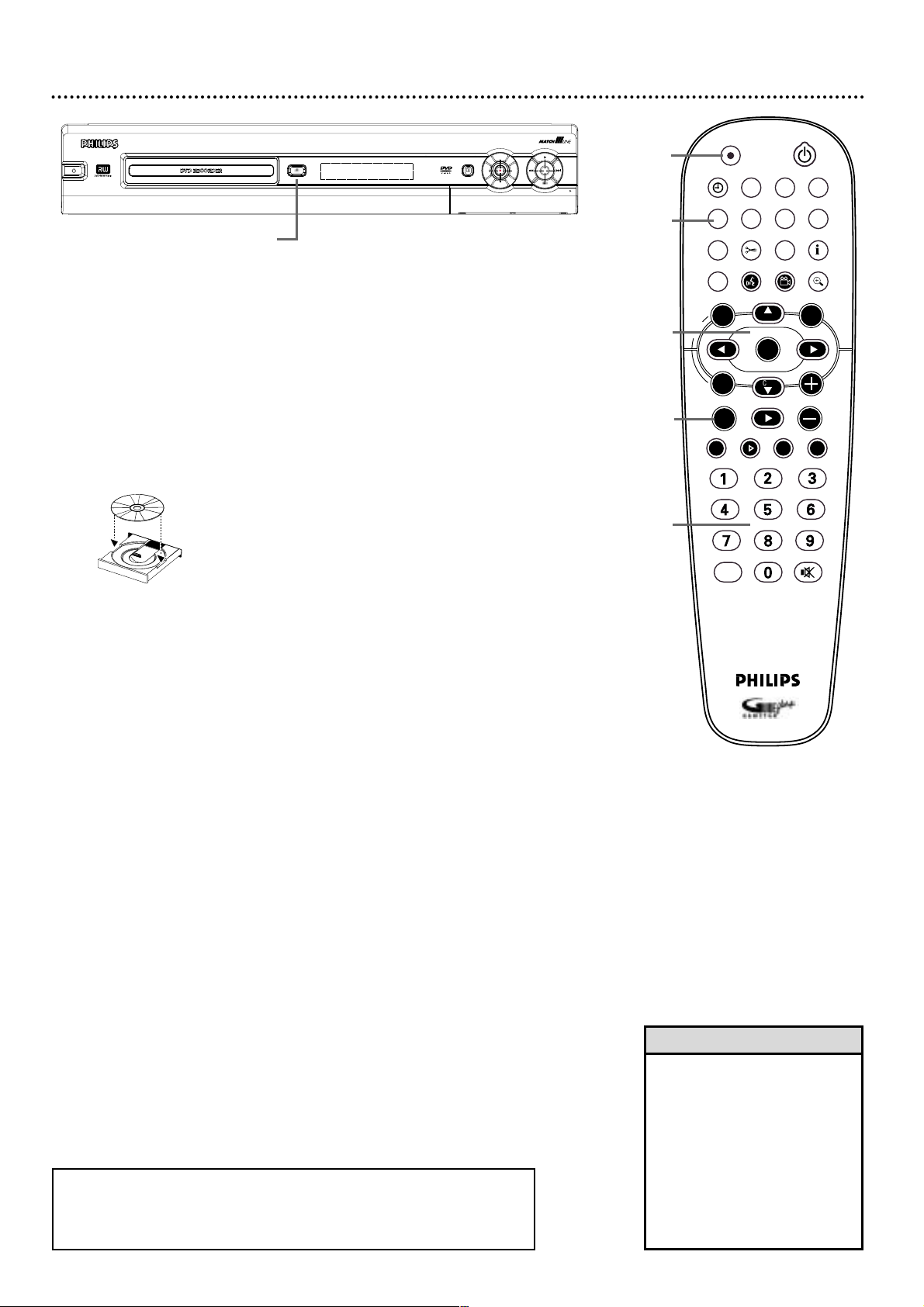
1
Press OPEN/CLOSE A on the front of the Recorder to open the
disc tray. (Or, press and hold STOP C on the remote control for
about three seconds to open or close the Disc tray.)
2
Insert a recordable DVD+RW or DVD+R, with the label facing
up. Press OPEN/CLOSE A to close the disc tray.The Index
Picture Screen will appear. See page 31. If the Disc is empty and has
no recordings,“EMPTY DISC” will appear on the display panel.
3
Press 9CH- to select an empty Title box on a DVD+RW. To
avoid overwriting other recordings, choose the last Empty Title box.
On a DVD+R, the Recorder always records at the end of the Disc;
you do not need to select an Empty Title box.You can not overwrite
DVD+R recordings.
4
Press MONITOR to see TV channels through the Recorder.
5
Press 9CH-, 8CH+, or the Number buttons to select the
channel you wish to record.
To record material playing on equipment you connected to the
Recorder, select EXT1, EXT2, CAM1, or CAM2. Choose the EXT
(External) or CAM (Camera) channel that matches the jack to
which you connected the other equipment. For example, if you connected a camcorder to the S-VIDEO CAM1 jack on the front of the
Recorder, press 9CH- or 8CH+ to choose CAM1. CAM1 will
appear in the Tuner Information Box. See page 30.
If you are using a Cable Box/Satellite Receiver, set the Recorder to
channel 3 or 4. (Choose the output channel of your Cable
Box/Satellite Receiver.) Change TV channels at the Cable
Box/Satellite Receiver.
6
Press REC/OTR I to record the channel. Red record lights will
encircle the disc tray and the Record I button on the front of the
Recorder. Recording will begin after a few seconds. (The Disc has to
prepare for recording.) To pause recording, press PAUSE k once on
the remote.The red light encircling the Record I button will flash.
To resume recording, press PAUSE k or REC/OTR I.
7
Press STOP C to stop recording.The Index Picture Screen will
reappear after a few seconds. On a brief recording on a new
DVD+RW, formatting the Disc will take a minute.
P
O
W
E
R
O
N
/O
F
F
• You can not record only Audio
(sound) to a DVD+RW/DVD+R.
You must record both audio and
video (sound and picture).
• To erase a recording, see “Erase
this title” details on page 35.
• You cannot duplicate copyrighted DVDs, videotapes, or TV
broadcasts using this Recorder.
“COPY PROTECT” will appear
on the display panel.
Helpful Hints
STANDBY
REC/OTR
TIMER REC MODE PLAY MODE TV/DVD
MONITOR
•TV
DIM RETURN T/C
DISC MANAGER FSS SELECT
SUBTITLE
STOP TV VOLUME
PAUSESLOW
PLAY
AUDIO ANGLE ZOOM
GUIDE/TV
MUTECLEAR
`
i
CHCH
-
CHCH
+
OK
SYSTEM
DISCDISC
Ç
H Gk
MENU
7
4
3,5
5
6
1-2
● To play a DVD+R on another DVD Player, finalize the Disc. Follow the steps
on page 40.You cannot record or edit a DVD+R after you finalize it.
● To edit your recordings, see pages 35 and 38-39. However, editing changes
may not be accessible when you play the Disc on other DVD Players.
P
U
OPEN/CLOSE
STANDBY-ON
GUIDE
T
F
E
L
D
N
O
W
DVDR 80
R
I
G
H
T
OPEN
Page 22

22 Quick Disc Play
1
Press STANDBY-ON yyto turn on the DVD Recorder.
Turn on your TV. Set it to the correct Video In channel. See
pages 9-17. You should see the blue Philips DVD background picture
on the TV screen (if no Disc is in the Recorder).
2
Press OPEN/CLOSE A on the front of the Recorder to open the
disc tray. Load your Disc in the tray, with the label facing up and
the shiny side facing down. If the Disc (DVD) is two-sided, make
sure the label of the side you want to play is facing up.
3
Press OPEN/CLOSE A again to close the tray.
4
Play may start automatically. If not:
• For a DVD, a Disc menu may appear. Press 9CH-, 8CH+, ;,or
: to select an item, then press OK. Continue until you set up
all the features you want or until the Disc starts playing. Follow the
instructions in the DVD Disc menu. If Titles, Chapters, or features
are numbered in the menu, use the Number buttons on the remote
to choose an item.
• For an Audio CD, press PLAY : to start play.
• With a DVD+RW or DVD+R, an Index Picture Screen will appear.
See page 30. Press 9CH- or 8CH+ to select a Title; press
PLAY :. If the Disc is blank, the display panel will show “EMPTY
DISC.”
5
To stop play at any time, press STOP C.
If Auto resume is On, play will resume at the same point the next
time you play the Disc.To play the Disc from its beginning, restart
play from the Disc menu.
If Auto resume is Off, Resume : will appear in the top left corner
when you start to play the Disc later.While Resume : appears,
press PLAY : to resume play from the point at which you last
stopped it. Otherwise, play will start at the beginning of the Disc.
Auto resume is On when you purchase the Recorder. However, you
can turn it On or Off. See page 62.
• If the Disc is Locked by Access
Control, you must enter the fourdigit code or authorize the Disc.
See pages 54-56.
• DVDs have a region code.Your
Recorder will not play Discs that
have a region code different from
the region code of your Recorder.
The Recorder’s region code is 1
(one). See page seven.
Helpful Hints
CH
CH
DISC
5
2-3
1
4
1
OPEN/CLOSE
STANDBY-ON
POW
ER ON/O
FF
P
U
GUIDE
R
I
G
T
F
H
E
T
L
D
N
O
W
DVDR 80
OPEN
REC/OTR
TIMER REC MODE PLAY MODE TV/DVD
MONITOR
•TV
DISC MANAGER FSS SELECT
SUBTITLE
AUDIO ANGLE ZOOM
`
DISC
MENU
STANDBY
DIM RETURN T/C
GUIDE/TV
+
CH
OK
i
-
SYSTEM
H Gk
CH
STOP TV VOLUME
PLAY
Ç
PAUSESLOW
MUTECLEAR
Page 23

Title/Disc Menus, Chapter/Track Selection 23
Title/Disc menus
1
Press DISC MENU during Disc play.
For a DVD, if the current Title has a menu, the Title menu will
appear on the screen. Otherwise, the Disc menu will appear.The
menu may list languages, Chapters, or other features.
For a DVD+RW or DVD+R, the Index Picture Screen will appear.
See page 31.
2
Press 8CH+, 9CH-, ;, or : to select items in the menu or
Index Picture Screen, then press OK. Repeat this process until
you set up all the features you want or until play begins.
3
Or, to return to play at the same place on the Disc, press
DISC MENU again.
Chapter/Track Selection
1
Press Next ¢ during play to go to the next Track/Chapter.
Press Previous 4 once to return to the beginning of the
current Track/Chapter. Press Previous 4 repeatedly to step
back to previous Tracks/Chapters.
2
Or, to go directly to any Track/Chapter during play, press
the Number buttons to enter the Track/Chapter number.
The number will show briefly beneath “C” (Chapter) in the Menu
Bar at the top of the TV screen.The Menu Bar will disappear in a
few seconds.
Make sure the Track/Chapter number you enter is on the Disc. Make
sure the Chapter is within the current Title.
STANDBY
REC/OTR
TIMER REC MODE PLAY MODE TV/DVD
MONITOR
•TV
DIM RETURN T/C
DISC MANAGER FSS SELECT
SUBTITLE
STOP TV VOLUME
PAUSESLOW
PLAY
AUDIO ANGLE ZOOM
GUIDE/TV
MUTECLEAR
`
i
CHCH
-
CHCH
+
OK
SYSTEM
DISCDISC
Ç
H Gk
MENU
2
1,3
STANDBY
REC/OTR
TIMER REC MODE PLAY MODE TV/DVD
MONITOR
•TV
DIM RETURN T/C
DISC MANAGER FSS SELECT
SUBTITLE
STOP TV VOLUME
PAUSESLOW
PLAY
AUDIO ANGLE ZOOM
GUIDE/TV
MUTECLEAR
`
i
CHCH
-
CHCH
+
OK
SYSTEM
DISCDISC
Ç
H Gk
MENU
2
1
Page 24

24 Remote Control
STANDBY
REC/OTR
TIMER REC MODE PLAY MODE TV/DVD
MONITOR
•TV
DIM RETURN T/C
DISC MANAGER FSS SELECT
SUBTITLE
STOP TV VOLUME
PAUSESLOW
PLAY
AUDIO ANGLE ZOOM
GUIDE/TV
MUTECLEAR
`
i
CHCH
-
CHCH
+
OK
SYSTEM
DISC
Ç
H Gk
MENU
TV/DVD Button
Press to switch between TV and DVD
positions.The selected position will
appear briefly on the display panel.
Use TV position to watch one TV
channel while recording another. See
page 36.
T/C (Title/Chapter) Button
Press repeatedly to select “T”
(Title/Track) or “C” (Chapter) in the
Menu Bar. Press 8CH+ or 9CH- to
choose a Title,Track, or Chapter to
play. Press SYSTEM MENU to remove
the Menu Bar.The T/C button has no
effect in Monitor mode.
RETURN Button
Press to go to a previous menu.This
option is not always available.
ZOOM a Button
Press to access a (Zoom) in the
Menu Bar and enlarge the video
image. See page 49.
GREEN ANGLE Button
Press to select a different camera
angle during DVD play. See page 49.
Also use as directed for certain
GUIDE Plus+®System features. See
pages 43-47.
GUIDE/TV Button
Press to access or remove the GUIDE
Plus+®System. See pages 43-47.
PLAY : Button
Press to play a Disc.
MONITOR Button
Press to choose Disc mode or
Monitor mode. In Disc mode, use the
Index Picture Screen or view Disc
play. In Monitor mode, watch TV
channels through the Recorder or
make a recording. See page 21.
DIM Button
Press repeatedly to adjust the bright-
ness of or to turn off the display on
the front of the DVD Recorder.
SUBTITLE Z Button
Press repeatedly during DVD play to
select a subtitle language. See page 48.
BLUE AUDIO YYButton
Press repeatedly to select a different
DVD audio language or soundtrack.
See page 48. Also use as directed for
certain GUIDE Plus+®System features.
See pages 43-47.
DISC MENU Button
Press during play to access a DVD’s
Title or Disc menu. See page 23.
Press to see the Index Picture Screen
of a DVD+RW/DVD+R. See page 31.
8CH+, 9CH-, ;, : Buttons
Press to select menu items.
Press 8CH+ and 9CH- to change
TV channels at the Recorder in
Monitor mode.
SYSTEM MENU Button
Press to access or remove the
Recorder’s Menu Bars. See page 28.
STOP C Button
Press to stop Disc play or recording.
Press and hold the STOP Cbutton for
three seconds to open or close the
Recorder’s disc tray.
The following buttons will work with
some Philips TVs when you hold down
the TV button on the side of the
remote. Hold down the TV button at
the same time you press these buttons.
Otherwise, these buttons will change
channels or power at the Recorder.
• 8CH+ or 9CH-
Press to change TV channels at the TV.
• Number buttons
Press to choose a channel at the TV.
• STANDBY
22
Press to turn on or off the TV.
TV
Button
Page 25

Remote Control (cont’d) 25
REC MODE Button
Press repeatedly to select a recording
speed.This determines the quality of
the recording and the length of time
you can record. See page 37.
REC/OTR
I Button
(Record/One-Touch Recording)
Press to start a recording. See page
21. Press to start a One-Touch
Recording. See page 34.
TIMER X Button
Press to set a timer recording in the
GUIDE Plus
®
System. See pages 43-47.
DISC MANAGER Button
Press to access the Disc Manager
information. See pages 41-42.
FSS $ Button
(Favorite Scene Selection)
Press to see or remove the Favorite
Scene Selection menu during play of a
DVD+R or DVD+RW. See page 39.
Previous 4 Button
Press to go to the beginning of the
current Chapter/Track. Press repeat-
edly to go to the beginning of previ-
ous Chapters/Tracks. See page 23.
Number Buttons
Press to select numbered items in a
menu. See page 22.
Press to play a specific Chapter or Track.
See page 23.
Press to select a TV channel in Monitor
mode.
PLAY MODE Button
Press during Disc play to choose a
Repeat, Shuffle, or Scan mode.
STANDBY yyButton
Press to turn on or off the power of
the Recorder.
i (information) Button
Press to see program details in the
GUIDE Plus+®System. See pages 43-47.
SELECT Button
Press to choose an item in the
GUIDE Plus®System.
OK Button
Press to acknowledge or approve a
menu selection.
TV VOLUME +/- Buttons
Press to increase or decrease the TV
volume.
Next ¢
Press to skip to the next Chapter or
Track during play. See page 23.
MUTE H Button
Press to silence or restore the TV
volume. Point the remote toward the
TV, not the Recorder.
PAUSE k Button
Press once to pause play. Press repeatedly to advance a picture one frame at
a time. See page 50.
SLOW H Button
Press repeatedly to play a Disc at 1/2,
1/4, or 1/8 the normal speed. See
page 51.
CLEAR Button
Press to remove the GUIDE Plus
®
System menus.
STANDBY
REC/OTR
TIMER REC MODE PLAY MODE TV/DVD
MONITOR
•TV
DIM RETURN T/C
DISC MANAGER FSS SELECT
SUBTITLE
STOP TV VOLUME
PAUSESLOW
PLAY
AUDIO ANGLE ZOOM
GUIDE/TV
MUTECLEAR
`
i
CHCH
-
CHCH
+
OK
SYSTEM
DISC
Ç
H Gk
MENU
Page 26

26 Front Panel
GUIDE
OPEN
STANDBY-ON
DVDR 80
OPEN/CLOSE
U
P
L
E
F
T
R
I
G
H
T
D
O
W
N
S-VIDEO
VIDEO
AUDIO
L
R
DV IN
CAM 2
CAM 1
STANDBY-ON yyButton
Press to turn on or off the Recorder.
Disc Tray
Insert a Disc here. Load the Disc with the label
facing up. See pages 21-22.
Stop C button
Press to stop Disc play or recording.
Next G and Previous H buttons
Press H to go to previous Chapters/Tracks or
to the beginning of the current one. Press G to
skip forward to the next Chapter/Track.
Play : button
Press to play a Disc.
UP/DOWN/LEFT/RIGHT Buttons
Use these buttons to move through menus.
Press the UP and DOWN buttons to change TV
channels at the Recorder in Monitor mode.
Record I button
Press to begin recording the current TV channel
or video source.A red light will encircle the
Record I button and the disc tray during recording. See page 21.
GUIDE button
Press to access or remove the GUIDE Plus+
®
System. See pages 43-47.
OPEN/CLOSE A button
Press to open or close the Disc tray.
Display Panel
Information about the current status of the Recorder or Discs appears here.
This may include the current time, the elapsed playing time of a Disc, or the
current TV channel.
Remote sensor
The sensor receives signals from the remote. Point the remote here, not at
your TV, when using the remote control to operate the DVD Recorder.
CAM (Camera) jacks
DV IN CAM 2; S-VIDEO, VIDEO, and AUDIO In CAM 1
To access these jacks, flip down the door as indicated by the OPEN : label
on the door. Use these jacks when connecting a Camcorder or other equipment to the DVD Recorder. See page 17. When recording material that is
playing on the other equipment, use the 8CH+ or 9CH- buttons in Monitor
mode to select the CAM channel that matches the jack to which the equipment is connected.
If your Personal Computer has an IEEE 1394 Firewire connector, you may
connect it to the Recorder’s DV IN CAM 2 jack. Limited applications are
available.
Page 27

Rear Panel 27
S-VIDEO
(Y/C)
ANTENNA
TV
S-VIDEO
(Y/C)
VIDEO
(CVBS)
VIDEO
(CVBS)
COMPONENT
VIDEO
AUDIO
COMPONENT
VIDEO
AUDIO
Y
P
B
P
R
Y
P
B
P
R
IN - EXT 2 IN - EXT 1
OUT 2 OUT 1
480p/480
i
COAX OUT
G-LINK
DIGITAL AUDIO OUT
OPTICAL OUT
MAINS
AUDIO
L
R
AUDIO
L
R
DIGITAL AUDIO OUT
MAINS ~ jack
Connect the supplied AC power cord here. See pages 10-16.
TV jack
Connect the supplied RF coaxial cable to the Recorder’s TV jack and to
the RF IN or ANTENNA IN jack (75 ohm) on your television.
ANTENNA jack
Connect your antenna or Cable TV signal here. See pages 10-16.
IN EXT 2 jacks
Use these jacks to receive picture and sound from other equipment, such
as a Camcorder or VCR.You will use these if you copy videotapes to a
DVD+R, for example. See page 17. You only need one video connection
from the other equipment, so use either VIDEO (CVBS) or S-VIDEO (Y-C).
• VIDEO (CVBS): Use a video cable to connect this jack to the Video
Out jack of other equipment.
• AUDIO L/R (left/right): Connect audio cables here and to the
Audio Out jacks of other equipment.
• S-VIDEO (Y-C): Use an S-video cable to connect this jack to the S-
Video Out jack of other equipment.
•
Use the same EXT (external)
number for each pair of audio
and video connections. For
example, if you use IN-EXT 2
S-VIDEO (Y/C), use the IN-EXT
2 AUDIO L/R jacks.
IN-EXT means this jack is
bringing IN the audio and video
from an EXTERNAL or separate piece of equipment.
•
Do not touch the inner pins of
the jacks. Electrostatic discharge may damage the unit
permanently.
•
You only need one audio and
one video connection to a TV.
You will not use all the jacks.
There are multiple jacks so you
can connect to different TV
styles or to other equipment.
Helpful Hints
IN EXT 1 jacks
Use these jacks to receive picture and sound from other equipment,
such as a Camcorder or VCR, that has Component Video.You will use
these if you copy videotapes to a DVD+R, for example. See page 17.
• AUDIO L/R (left/right): Connect audio cables here and to the
Audio Out jacks of the other equipment.
• COMPONENT VIDEO (Y PB PR): Connect these jacks to the
Component Video Out jacks of the other equipment.
OUT 1 and OUT 2 jacks
Use these jacks to connect the Recorder to your TV and/or Stereo.
• VIDEO (CVBS): Connect the yellow video cable here and to the TV’s
Video In jack. See page 14.
• S-VIDEO (Y-C): Connect an S-Video cable here and to a TV’s S-
Video In jack. See page 13.
• COMPONENT VIDEO (Y P
B PR): Connect Component Video
cables (red, blue, green) here and to a TV’s Component Video In jacks.
See page 12.
• AUDIO L/R (Left/Right): Use audio cables (red, white) to connect
these jacks to the Audio In jacks of a TV or Stereo. See pages 12-15.
DIGITAL AUDIO OUT jacks
• COAX OUT: Connect a digital audio coaxial cable here and to the
digital audio Coaxial In jack of a Stereo. See page 16.
• OPTICAL OUT: Connect a digital audio optical cable here and to
the digital audio Optical In jack of a Stereo. See page 16.
G-LINK jack
Connect the G-Link cable here to have the Recorder operate a Cable
Box for the GUIDE Plus+
®
System. Remove the Demonstration Pin from
this jack first when you receive the Recorder. See pages 18-20.
Page 28

28 Menu Bars
In addition to using the shortcut buttons on the remote to select features, you
can use the Menu Bars.You can not access the Menu Bars during recording.
When a Menu Bar is on the screen, press 8CH+, 9CH-, ;, or : on the
remote to select an item or to change the setting of an item.
The 98; : symbols in the Menu Bar mean more items are available.
Menu Bar 1
*Press SYSTEM MENU once to access Menu Bar 1.The following
items are in Menu Bar 1. Depending on the Disc, you may not be able to
access each item at all times. Only available features can be selected.
User Preference Settings Set your preferences for audio and video
quality. Set up Languages,Access Control, Record Settings, Installation
features, and other Recorder features.
Title Select to play a Title or Track. Use the Number buttons or
8CH+ or 9CH- to select the Title or Track you want.
Chapter Select to play a Chapter. Use the Number buttons or
8CH+ or 9CH- to select the Chapter you want.
Audio Language If the current DVD has multiple audio soundtracks,
choose one here. Check the Disc case for details. See page 48.
Subtitle Language If the current Disc has subtitles,select a language
here. See page 48.
Angle Select to choose a different camera angle, if available, during
DVD play. See page 49.
Zoom Select to enlarge the picture by 1.33, 2, or 4 times the normal
size during play. See page 49.
Menu Bar 2
*While in Menu Bar 1, press : repeatedly to move to Menu Bar 2.
The following items are in Menu Bar 2.
Analog Output Select d, then press 8CH+ or 9CH- to choose
Stereo (st), or Dolby Surround compatible (sur). See page 50.
Frame-by-frame play Select for forward or reverse frame-by-frame
play. Press 9CH-, then press ; or : to move the picture one frame at
a time. See page 50.
Slow motion Select to slow the speed of DVD, DVD+R, or DVD+RW
play. See page 51.
Fast motion Select to play a Disc forward or backward at four, eight,
or 32 times the normal play speed. Press 9CH-, then press ; or : to
choose a backward (-) or forward speed. See page 51.
Time Search Select to enter a specific time within the current Track,
Title, or Chapter at which you want play to begin. See page 52.
W
Z
Y
d
H
E
a
X
Page 29

Disc status icons
recording
stop
pause play
pause recording
fast forward
fast reverse
slow motion
Disc type icons
DVD+R
DVD+RW
DVD-Video
Super Video-CD
Video-CD
no Disc
Disc error
H
1/4
J
x4
K
x4
0 ;
pause
;
pause
9
stop
0
rec
Status Box
The Status Box shows the current status of the Recorder and information about the current Disc,
including Disc type, total playing time, and elapsed playing time. Set Status box to On if you want to see
the following icons briefly when you access a feature. See page 57.
On-screen Symbols, Status Box 29
Scan The first 10 seconds of each
Chapter/Track will play. See page 52.
Repeat All The entire Disc will play
repeatedly. See page 53.
Repeat Title The current Title will play
repeatedly. See page 53.
Repeat Chapter The current Chapter
will play repeatedly. See page 53.
Repeat A Point A for Repeat A-B play
has been entered. See page 53.
Repeat A-B A segment of the Disc will
play repeatedly. See page 53.
Angle Multiple angles are available.
See page 49.
Locked The Disc is Locked and cannot
play without your code. See page 55.
Safe The current Disc is authorized to
play. See page 55.
“X” The feature you just attempted is not
available on the current Disc or at the
current time.
Shuffle The Tracks or Chapters will play
in random order. To start shuffled play,
press PLAY MODE repeatedly until
“shuffle” appears on the TV screen.
On-screen Symbols
The following symbols will appear briefly on the TV screen when you activate some Disc features.
scan
2/2
locked
safe
repeat
title
chapter
A -
A - B
DVD+R
DVD
SVCD
RW
VCD
no disc
error
shuffle
Page 30

30 Information Boxes
Warning box
Special messages appear in a red bar at the bottom of the TV screen when
appropriate, as in the example below.
Tuner Information box
Appears on the left side of the TV screen and identifies the current TV
channel or Video source in Monitor mode. For example, if EXT1 appears in
the Tuner Information Box, you can view or record the material that is playing on the equipment that is connected to the IN EXT 1 jacks on the rear
of the Recorder.
Make sure you connected an Antenna or Cable TV signal to the Recorder’s
ANTENNA jack. See pages 10-16. Press MONITOR to put the Recorder in
Monitor mode and view the TV channel or playback from other equipment.
Timer Information box
Displays the start time or date of the next scheduled timer recording and
appears in the Index Picture Screen.You cannot remove it from the Index
Picture Screen.
It may appear briefly at the beginning of a timed One-Touch Recording. It
does not appear during recording or Disc play.
In Monitor mode, the Timer Information box will appear for a few seconds,
then disappear.
Disc locked
012
012
10:15 pm
Copy-protected
signal
Current TV
channel
No signal - Channel is not
receivable or no equipment is
connected to this jack.
Timer recording
due later today
Timer recording set
for another day
within the
upcoming year
The time at which
the current
One-Touch
Recording will end.
Current time;
no timer recordings
are scheduled.
Page 31

Current Title and Title description
Includes program name (or channel or
source and time it was recorded), length
of recording, the speed in which it was
recorded, and the date of recording (if
clock was set).
Disc Manager Number
Indicates the number assigned to the disc
in the Disc Manager. See pages 41-42.
Index Picture
An image representing a recording. An
empty box represents an area on the Disc
that is empty. To personalize the Index
Picture, see page 39.
Timer Information Box
Displays the current time or the time/date
of the next timer recording. See page 30.
Tuner Information Box
Displays the current TV channel or video
source. See page 30.
Index Picture Screen 31
The Index Picture Screen shows your recordings. It appears when you
insert a DVD+R or DVD+RW or when you stop play or recording.
An Index Picture represents each recording. Next to each Index Picture is
the program name (or channel and time), length, speed, and date. If GUIDE
Plus+®System data is available, the Recorder uses that data to name the
recording.
Empty disc areas also show in the Index Picture Screen. “Empty title” and
the amount of remaining recording time may appear beside an empty Index
Picture box. This indicates blank space that is available for additional
recording.“Deleted title” and the amount of blank space will appear in
blank areas of a DVD+R.You cannot reuse this space for recordings though.
The Index Picture Screen will dim after several minutes of no use. It will
brighten again when you use the Recorder or its remote.
Titles
Three index pictures appear at a time. Press 8CH+ or 9CH- to move to
other screens. Press STOP C to go directly to the first recording. Press
8CH+ repeatedly to go to the Disc Information Screen. See page 38.
Disc Bar
The Disc Bar appears at the right of the Index Picture Screen. Its Disc
Pointer indicates your current position on the Disc. Moving through the
recordings by pressing 8CH+ or 9CH- moves the Disc Pointer. On a
DVD+RW, resume play or recording from this point by pressing OK to play
or REC/OTR I to record. Later recordings will be overwritten. On a
DVD+R, resume play from the Disc Pointer location by pressing OK.
However, on a DVD+R, recording automatically begins at the last empty
title space when you press REC/OTR I.
Title Settings Menu
When you select an Index Picture, press : to go to the Title Settings menu
for that recording. Here, you can edit the current Title name, play the entire
Title, or erase the selected Title. See page 35.
Disc
Pointer
Indicates the
selected
position on
the Disc.
Disc Bar
X !
Wed 10/22
L
C10 08:00AM
00:01:25 . M1
Thu 10/09/2003
Basketball
B
0100:02:58 . M2
Sun 09/28/2003
Food channel
00:38:53 . M6
Sun 09/28/2003
K
2
¡
012
Disc 001
Page 32

32 Clock
Once the GUIDE Plus+®System is operating, it will control the time and date
of the Recorder. Until then, set the clock by following these steps.
After the GUIDE Plus+®System receives the clock data, it will override any
earlier clock settings.You cannot change the time information once the
GUIDE Plus+
®
System has set it.
1
Press SYSTEM MENU. Press ; to select in the top left
corner of the Menu Bar at the top of the TV screen.
2
Press 9CH- repeatedly to select at the end of the second
menu. Press :. This is not always accessible under some GUIDE
Plus+®System circumstances.
3
Press 9CH- repeatedly to select Time/Date, then press :.
If the time already is set by the GUIDE Plus+®System, you will see a message
“Not valid to change; Valid data received via Guide.” You cannot change the
clock setting to override the time provided by the GUIDE Plus+® System. Press
SYSTEM MENU repeatedly to remove the menu.
4
Press 8CH+ or 9CH- to choose Automatic or Manual, then
press :.
5
● Manual
Press 8CH+ or 9CH- to choose Time,AM/PM,Year, Month,
date and Daylight Saving. Press ; or : to set each item
correctly. Or, press the Number buttons to quickly enter the time
in hours and minutes.
● Automatic
Press 8CH+ or 9CH- to choose PBS Channel, Daylight
Saving, or Time Zone. Press ; or : to change the setting of
each item.
For PBS Channel, choose the channel number of your PBS station, then
press OK. If you do not know your PBS channel number, choose Auto.
The Recorder will find the PBS station for you and set the time.
Turn Daylight Saving On or Off. Choose Auto if you want the clock
set according to the PBS station’s Daylight Savings Time schedule.
Finally, choose your Time Zone. If you want the Recorder to use the
time zone from which your PBS station broadcasts, choose Auto.If
your PBS station broadcasts from a different time zone than the one in
which you live, be sure to select your time zone.
6
When all the information is correct, press OK.
7
Press SYSTEM MENU repeatedly to remove the menus, then
press STANDBY yyto turn off the Recorder.
• The Recorder may set the clock
automatically after you complete Initial Setup.
• The Recorder can use the PBS
channel to set the clock only if
the PBS channel is memorized.
To add (memorize) a channel,
see page 33.
• If you change any item manually, PBS Channel will change
to Off.
Helpful Hints
STANDBY
REC/OTR
TIMER REC MODE PLAY MODE TV/DVD
MONITOR
•TV
DIM RETURN T/C
DISC MANAGER FSS SELECT
SUBTITLE
STOP TV VOLUME
PAUSESLOW
PLAY
AUDIO ANGLE ZOOM
GUIDE/TV
MUTECLEAR
`
i
CHCH
-
CHCH
+
OK
SYSTEM
DISCDISC
Ç
H Gk
MENU
1-6
7
1,7
Time/date
Manual
K
u Time s 04:24 B
L
AM/PM PM
Year 2002
Month 02
Date 14
Daylight Saving Auto
To exit press
SYSTEM MENU
Time/date
Automatic
K
u PBS Channel s 010 B
L
Daylight Saving Off
Time Zone Auto.
To store
Press OK
Page 33

Channel Programming 33
In the brief period between your Initial Setup of the Recorder and the
setup of the GUIDE Plus+
®
System, you can adjust the TV channel listings.
This option will not be available for selection once the GUIDE Plus
®
System
is in use and receiving programming data.The GUIDE Plus®System will
override any channel settings you make manually.
1
Press SYSTEM MENU. Press ; to select in the top left
corner of the Menu Bar at the top of the TV screen.
2
Press 9CH- repeatedly to select at the end of the second
menu page. Press :.
3
Press 8CH+ or 9CH- to select Auto Ch. Programming,
then press OK. “Searching for TV channels” will appear, along with
a scale showing channels that are being memorized.The number of
channels found will show on the screen as the searching progresses.
This will take a few minutes, depending on the channels available.
4
When the channel search finishes,“Auto ch. search complete” will
appear, along with the total number of channels found.
Press SYSTEM MENU. The Installation menu will reappear.
If you are satisfied with the channels found, press SYSTEM
MENU again to remove the menu. You are finished.
To add or delete additional channels, press 8CH+ or 9CH-
to select Add/Delete Channels, then go to step 5.
5
Press :. A channel list will appear. Beside each channel number,
you will see “Delete” or “Add.”
6
Press 8CH+ or 9CH- to select the channel number you
want to add or delete, then press ; or : to choose Add or
Delete for that channel. Press OK to store your choice.
Repeat to add or delete other channels.
7
Press SYSTEM MENU repeatedly to remove all the menus
when you are finished.
• Only added channels are
accessible using CH+8/CH-9.
Select deleted channels with
the Number buttons instead.
• The Recorder detects whether
you have an Antenna or Cable
TV signal. If you are receiving
limited channels, check the
Cable/Antenna setting. Follow
steps 1-2 above. Press CH-
9
to choose Cable/Antenna, then
press OK. Press CH+8or CH-
9
to choose Cable or Anten.
Press OK, then press SYSTEM
MENU. Press OK again to
reset the channels.When the
channel search ends, press
SYSTEM MENU.This is not
available once the GUIDE
Plus+®System controls the
channel list.
Helpful Hints
STANDBY
REC/OTR
TIMER REC MODE PLAY MODE TV/DVD
MONITOR
•TV
DIM RETURN T/C
DISC MANAGER FSS SELECT
SUBTITLE
STOP TV VOLUME
PAUSESLOW
PLAY
AUDIO ANGLE ZOOM
GUIDE/TV
MUTECLEAR
`
i
CHCH
-
CHCH
+
OK
SYSTEM
DISCDISC
Ç
H Gk
MENU
1-6
1,4,7
Installation
K
u B Auto Ch. Programming B
L
Add/Delete Channels
Time/Date
Cable/Antenna
To exit press
SYSTEM MENU
Installation
Add/Delete Channels
KK...
u Channel 001 s Delete B
L
Channel 002 Add
Channel 003 Add
Channel 004 Add
Channel 005 Add
Channel 006 Add
L
...
To exit press
SYSTEM MENU
Page 34

34 One-Touch Recording
1
Place a recordable DVD+RW or DVD+R in the Recorder.
2
In the Index Picture Screen of a DVD+RW, press 8CH+ or
9CH- to select an Empty Title (or empty Index Picture box)
that has enough time for the recording. Or, select the place at which
you want to start the new recording in order to overwrite other
recordings. See page 36.
You may skip this step if you use Safe Record. See step 5.
Or, if you are using a DVD+R, you may skip this step. Recordings on
a DVD+R are made at the end of the Disc automatically. Previous
recordings are not overwritten.
3
Press MONITOR to see TV channels through the DVD Recorder.
4
Press 8CH+, 9CH-, or Number buttons to select a channel
to record. You cannot change channels during recording.
If you are using a Cable Box/Satellite Receiver that has a single RF
Out/TV Out/Antenna Out/75 ohm jack, set the DVD Recorder to
channel 3 or 4 in Monitor mode. (Choose the output channel of
your Cable Box/Satellite Receiver.)
If your Cable Box/Satellite Receiver has Audio/Video Out jacks, set
the Recorder to an EXT channel. Choose the EXT channel that corresponds to the jacks you used on the rear of the DVD Recorder
(the jacks to which you connected the Cable Box/Satellite Receiver).
Then, change TV channels at the Cable Box/Satellite Receiver.
5
Press REC/OTR I twice to start a 30-minute recording.
Press REC/OTR I repeatedly to record longer segments in
thirty-minute increments.The length of recording available depends
on the current recording mode/speed and the amount of time available on the Disc. See page 37. Recording will begin soon after you
press REC/OTR I.The Disc takes a few seconds to prepare for
recording.
Or, use Safe Record to have the Recorder automatically find the
empty space at the end of a DVD+RW; this prevents overwriting
other recordings.To do so, press and hold REC/OTR I for about
two seconds, or until SAFE REC appears on the Recorder’s display
panel.Then, press REC/OTR
I repeatedly to choose the time length
you want for your recording.
6
Press |STOP C if you need to stop the recording before the
designated end time. Otherwise, the Recorder will automatically
stop recording at the designated end time and turn itself off.
Or, if you only pressed REC/OTR I once, the Recorder will record
the current channel or source until the end of the Disc is reached.
Then the Recorder will turn itself off.
• “Disc locked” will appear on the
TV if a protected DVD+RW or
DVD+R is in the Recorder.
• If the power fails during recording, the Index Picture Screen may
not match the actual video content on the Disc.The last recorded Title may be lost.A power failure or unit failure/system crash
also may destroy all the material
recorded on a Disc.
• When the Disc is full,“End of
Disc” will appear on the TV. DISC
FULL will show on the Recorder’s
display panel.
• Press SYSTEM MENU during
recording to access or remove the
Status,Tuner, or Timer Information
box. See pages 29-30.
• The recommended operating
temperature range for the
Recorder is 32°F-122°F for
DVD+RW recording and 32°F104°F for DVD+R recording.
Exceeding these ranges may
cause unstable recording results.
Helpful Hints
● To play a DVD+R on another DVD Player, finalize the Disc. Follow the steps
on page 40.You cannot record or edit a DVD+R after you finalize it.
● To edit your recordings, see pages 35 and 38-39. However, editing changes
may not be accessible when you play the Disc on other DVD Players.
● To erase a recording, see “Erase this title” details on page 35.
STANDBY
REC/OTR
TIMER REC MODE PLAY MODE TV/DVD
MONITOR
•TV
DIM RETURN T/C
DISC MANAGER FSS SELECT
SUBTITLE
STOP TV VOLUME
PAUSESLOW
PLAY
AUDIO ANGLE ZOOM
GUIDE/TV
MUTECLEAR
`
i
CHCH
-
CHCH
+
OK
SYSTEM
DISCDISC
Ç
H Gk
MENU
2,4
3
4
5
6
Page 35

The Title Settings Menu lets you rename a Title or recording on a
DVD+RW/DVD+R. From the same menu, you can play the entire selected
Title or erase the chosen Title from the Disc.
1
When play is stopped and a DVD+RW or DVD+R is in the
Recorder, the Index Picture Screen will appear. See page 31.
2
Press 8CH+ or 9CH- to select the Index Picture of the
recording you want to name, play, or erase, then press :.
The Title settings menu will appear.
3
Press 8CH+ or 9CH- to select Name, Play full title, or
Erase this title. Continue accordingly at step 4.
4
●
Name
Press :. The first character of the Title name will be selected.
Press 8CH+ or 9CH- to change the character.
Press SELECT to switch between upper and lower case letters. Press
CLEAR to erase a character.To move to the previous or next character, press ; or :.
When the Title is complete, press OK. Storing Name will
appear while the name is stored.
●
Play full title
Press OK to start Disc play at the Title you selected.
●
Erase this title
Press OK. The Recorder will ask you to confirm that you really
want to erase the entire Title. Press OK again to start erasing
the Title. “Erasing title” will appear during erasure.When erasing is
complete, the Index Picture Screen will reappear.
(If you do not want to erase the Title, press ; instead.)
5
Press ;to return to the Index Picture Screen if necessary.
Title Settings Menu 35
X !
Wed 10/22
L
C10 08:00AM
00:01:25 . M1
Thu 10/09/2003
Basketball
B
0100:02:58 . M2
Sun 09/28/2003
C10 12:00AM
00:38:53 . M6
Sun 09/14/2002
K
2
¡
012
Settings for title XXXXX
Name XXXXX
Play full title
s
K
Erase this title Press OK
Settings for title XXXXX
Name s
K
L
XXXXX
B
Play full title
Erase this title
Settings for title XXXXX
Name XXXXX
s
K
L
Play full title Press OK
Erase this title
• If you erase a Title from a
DVD+R, you can’t reuse the
space for other recordings.
“Deleted title” will appear
beside an empty Index Picture
box. Recordings are made at the
end of a DVD+R automatically.
Helpful Hint
STANDBY
REC/OTR
TIMER REC MODE PLAY MODE TV/DVD
MONITOR
•TV
DIM RETURN T/C
DISC MANAGER FSS SELECT
SUBTITLE
STOP TV VOLUME
PAUSESLOW
PLAY
AUDIO ANGLE ZOOM
GUIDE/TV
MUTECLEAR
`
i
CHCH
-
CHCH
+
OK
SYSTEM
DISCDISC
Ç
H Gk
MENU
2-5
Page 36

36 Append Recording, Record One Channel/Watch Another
Append recording
To add a new video recording to an earlier recorded Title, follow these
steps.This feature is not available on DVD+Rs, which always record at the
end of the Disc.
1
In the Index Picture Screen, press 8CH+ or 9CH- to select
the Title to which you want to add a recording.
2
Press PLAY :.
3
When you reach the point at which you want to start the
new recording, press PAUSE k.
4
Press MONITOR, then press 8CH+ or 9CH- to select the
channel (or other equipment) you want to record.
5
Press REC/OTR I. The new recording will start at the point you
selected and overwrite the video material beyond this point, including later Titles.
6
Press STOP C to stop recording.
STANDBY
REC/OTR
TIMER REC MODE PLAY MODE TV/DVD
MONITOR
•TV
DIM RETURN T/C
DISC MANAGER FSS SELECT
SUBTITLE
STOP TV VOLUME
PAUSESLOW
PLAY
AUDIO ANGLE ZOOM
GUIDE/TV
MUTECLEAR
`
i
CHCH
-
CHCH
+
OK
SYSTEM
DISCDISC
Ç
H Gk
MENU
1,4
4
2
3
5
6
Record One Channel/Watch Another
1
Press REC/OTR I to record the current TV channel. A red
light will encircle the Record I button and the disc tray on the
Recorder to indicate recording is in progress.
2
Press TV/DVD on the Recorder’s remote to put the
Recorder in TV position. TV will appear briefly in the lower left
area of the Recorder’s display panel.
3
Use the TV remote to select the channel you want to watch
at the TV. (If you have a Philips TV, hold down the TV button on
the side of the Recorder’s remote and use the 8CH+ and 9CH-
buttons to change channels at the TV. See page 24.)
4
To return to the recording, use the TV remote to reselect
the TV channel at which you usually view the DVD
Recorder. This may be a Video In channel or channel 3 or 4,
depending on how you connected the DVD Recorder to the TV.
The channel being recorded will reappear on the TV screen.
5
Press TV/DVD on the Recorder’s remote control to return
the Recorder to DVD position. DVD will appear briefly on the
Recorder’s display panel.
6
To stop recording, press STOP C.
STANDBY
REC/OTR
TIMER REC MODE PLAY MODE TV/DVD
MONITOR
•TV
DIM RETURN T/C
DISC MANAGER FSS SELECT
SUBTITLE
STOP TV VOLUME
PAUSESLOW
PLAY
AUDIO ANGLE ZOOM
GUIDE/TV
MUTECLEAR
`
i
CHCH
-
CHCH
+
OK
SYSTEM
DISCDISC
Ç
H Gk
MENU
2,5
1
3
6
Page 37

Record Settings, Chapter Markers 37
Record Settings
1
Press SYSTEM MENU. Press ; to select in the top left
corner of the Menu Bar at the top of the TV screen.
2
Press 9CH- repeatedly to select in the second page of
menus, then press :.
3
Press 8CH+ or 9CH- to select Record mode, Auto chapters, or Filter mode. Proceed as described in step 4.
4
● Record mode
Press ; or : to choose M1, M2, M2x, M3, M4, M6, or M8,
then press OK. These recording speeds define the picture quality
of recordings and the maximum recording time for a Disc.
You also can choose a record mode by pressing REC MODE in
Monitor mode or in the Index Picture Screen.You can’t change
record modes during recording.
● Auto chapters
Press ; or : to choose On or Off, then press OK. If Auto
chapters is On, the Recorder will insert a Chapter marker every five
to six minutes during recording.To disable this feature, select Off.
To insert Chapter markers after recording, see page 39. To insert
Chapter markers manually during recording, see below.
● Filter mode
Press ; or : to choose Stndrd (Standard) or Sport, then
press OK. Select Sport to improve recording of images that move
quickly. Otherwise, choose Stndrd.
5
Press SYSTEM MENU repeatedly to remove the menus.
Chapter Markers
Chapter Markers let you move easily through recordings by pressing Next
¢ or Previous 4 during play.This gives you access to specific points on
a DVD+RW/DVD+R much as you would choose a Chapter on a DVD.
1
Press FSS $ during recording to insert a Chapter marker
at the current position. “Inserting chapter marker” will appear at
the bottom of the TV screen. The maximum number of markers
varies per Disc.When the maximum is reached,“Too many chapters” will appear. Delete some before inserting more. See page 39.
STANDBY
REC/OTR
TIMER REC MODE PLAY MODE TV/DVD
MONITOR
•TV
DIM RETURN T/C
DISC MANAGER FSS SELECT
SUBTITLE
STOP TV VOLUME
PAUSESLOW
PLAY
AUDIO ANGLE ZOOM
GUIDE/TV
MUTECLEAR
`
i
CHCH
-
CHCH
+
OK
SYSTEM
DISCDISC
Ç
H Gk
MENU
1-4
1,5
STANDBY
REC/OTR
TIMER REC MODE PLAY MODE TV/DVD
MONITOR
•TV
DIM RETURN T/C
DISC MANAGER FSS SELECT
SUBTITLE
STOP TV VOLUME
PAUSESLOW
PLAY
AUDIO ANGLE ZOOM
GUIDE/TV
`
i
CHCH
-
CHCH
+
OK
SYSTEM
DISCDISC
Ç
H Gk
MENU
1
Mode Picture quality Recording time per Disc
M1 Highest quality; least 1 hour
recording time per Disc
M2 Equals quality of 2 hours
a pre-recorded DVD
M2x Better quality than 2.5 hours
an S-VHS videotape
M3 Equals quality of 3 hours
an S-VHS videotape
M4 Better quality than 4 hours
a VHS videotape
M6 Equals quality of 6 hours
a VHS videotape
M8 Maximum recording time, 8 hours
almost VHS quality
Page 38

38 Editing: Disc Information Screen
You can change settings for a DVD+RW or unfinalized DVD+R from the
Disc Information Screen.
1
When in the Index Picture Screen, press STOP C to select
the first Title on the Disc.
2
Press 8CH+ to enter the Disc Information Screen.
3
In the Disc Information Screen, press : to enter the
Settings menu. You cannot do this if a DVD+R is finalized.
4
Press 8CH+ or 9CH- to select Disc name, Protection,
Erase disc (DVD+RW only), Make edits compatible
(DVD+RW only), or Finalize disc (DVD+R only). Proceed as
follows, depending on which feature you want to adjust.
●
D
isc name (DVD+RW and DVD+R)
Press :. Press ; or : to choose the character position,
then press 8CH+ or 9CH- to enter a character. Press
SELECT to alternate between capital and lower case characters.
Press CLEAR to erase a character (the space will remain). When
the name is complete, press OK.
●
Protection
(DVD+RW and DVD+R)
Press :. Press 8CH+ or 9CH- to select Protected or
Unprotected, then press OK. If you protect the Disc, y
ou cannot
edit or record it
.“Disc locked” will appear on the TV briefly if you
try to do so.To edit or record again, select Unprotected.
Remember, protecting a DVD+R is not the same as finalizing it.
Finalization cannot be undone.
●
Erase disc
(DVD+RW only)
Press OK.
“This will erase all titles Press OK to confirm” will
appear. Press OK again to begin erasing. (If you decide not to
erase the Disc, press ;.) “Erasing disc” appears until erasing is complete.When the Disc is erased, the Index Picture Screen will reappear, showing the free space on the Disc.
● Make edits compatible (DVD+RW only)
Press OK.“This will take XX” and “Press OK to confirm” will
appear to indicate how long the action will take. (If you decide to
not make edits compatible, press ;.)
Press OK again. “Working ..” and a progress % bar will appear.The
Index Picture Screen will reappear when the process is complete.
Make edits compatible appears only if you have added Chapter
markers or made Chapters invisible on the DVD+RW. See page 39.
● Finalize Disc (unfinalized DVD+R only)
Press OK. “Finalizing disc” will appear during the process.This may
take a few minutes.Then, the Index Picture Screen will reappear.
You cannot unfinalize a DVD+R.You cannot record or edit the
DVD+R after you finalize it. A DVD+R will play on other DVD
Players only after you finalize it.
5
If necessary, press ; when you are finished and want to return
to the Disc Information Screen.
• Index Picture Screen details are
on page 31.
• If a DVD+R was recorded on a
different DVD Recorder, the settings may not be accessible.
• A disc name may contain a
maximum of 64 characters.
Helpful Hints
Settings for XXXXXX
sL01Disc name B sample
Protection Unprotected
Erase disc
Make edits compatible
DVD+RW example
STANDBY
REC/OTR
TIMER REC MODE PLAY MODE TV/DVD
MONITOR
•TV
DIM RETURN T/C
DISC MANAGER FSS SELECT
SUBTITLE
STOP TV VOLUME
PAUSESLOW
PLAY
AUDIO ANGLE ZOOM
GUIDE/TV
MUTECLEAR
`
i
CHCH
-
CHCH
+
OK
SYSTEM
DISCDISC
Ç
H Gk
MENU
2-5
1
Page 39

Editing 39
• The maximum number of
Chapters per Title varies. When
you reach the maximum,“Too
many chapters” will appear on
the screen. Delete Chapters
before making more.
• Favorite Scene Selection will dis-
appear if you do not edit anything for several minutes.
• You cannot undo a Title division.
The Index Picture Screen will
show two Titles instead of one;
both will have the same name.
Change the name in Title
Settings. See page 35.
• Editing changes on DVD+Rs will
be accessible only during play on
this Recorder.You can not edit a
DVD+R after it is finalized.
• Insert chapter markers during
recording by pressing FSS
$
where you want a marker.
Helpful Hints
Although editing changes may not be accessible when you play a DVD+R or
DVD+RW on DVD Players, the changes are available at the Recorder.
1
In the Index Picture Screen, press 8CH+ or 9CH- to select
the Title you want to edit. Press PLAY : to begin play.
2
During play, press FSS $ . The Favorite Scene Selection menu
will overlay the current video image.The current Title and Chapter
numbers will appear at the top of the screen.
3
Press 8CH+ or 9CH- to select Insert chapter marker,
Current chapter, Delete chapter marker, Delete all markers, New index picture, or Divide title (DVD+RW only).
4
● If you select Insert chapter marker, press OK. “Inserting
chapter marker” will appear briefly.This places a Chapter marker at
that point so you can go there quickly by pressing Next ∑ or
Previous 4.
● If you select Current chapter, press : (or SELECT) repeat-
edly to select Visible or Hidden. Press OK. By hiding chapters
or making them visible, you determine which chapters you want to
view. If you do not want to watch certain scenes (for example, commercials), insert Chapter markers at the beginning and end of the
scene, then hide that segment.You can then watch your recording
without the hidden chapters.The picture may freeze briefly between
scenes, but you will not see the hidden content.
● If you select Delete chapter marker, press OK. “Deleting
marker” appears briefly.This deletes the marker at the beginning of
the current Chapter. (This option is not always available.)
● If you select Delete all markers, press OK. “This will delete
all markers in this title. Press OK to confirm” will appear. Press OK
again. (If you decide not to delete all markers, press ;.)
(This option is not always available.)
● If you select New Index Picture, press PAUSE F or
SLOW H to accurately choose a frame of picture during
play. This frame will become the miniature picture that will appear
in the Index Picture Screen for the current Title.
When you reach the desired picture frame, press OK.“This
will update the index picture Press OK to confirm” will appear.
Press OK again. (If you decide not to select a new Index Picture,
press ;.) “Updating menu” will appear, then the Index Picture
Screen will reappear when the action is complete.
● If you select Divide title (DVD+RW only), press PAUSE F
to accurately choose the point at which you want to start
the new Title. Press OK.“This will divide this title into two sepa-
rate titles. Press OK to confirm” will appear. Press OK again. (If
you decide not to divide the Title, press ;.) “Dividing title” appears
until the action is complete; the Index Picture Screen will reappear.
5
Press FSS $ to remove the menu if necessary.
Favorite Scene Selection
01Insert chapter marker
K
L
Current chapter B Hidden
Delete chapter marker
Delete all markers
New index picture
Divide title
Press FSS to exit
W X
12
L
B
RW play
0:01:24
0:00:22
STANDBY
REC/OTR
TIMER REC MODE PLAY MODE TV/DVD
MONITOR
•TV
DIM RETURN T/C
DISC MANAGER FSS SELECT
SUBTITLE
STOP TV VOLUME
PAUSESLOW
PLAY
AUDIO ANGLE ZOOM
GUIDE/TV
MUTECLEAR
`
i
CHCH
-
CHCH
+
OK
SYSTEM
DISCDISC
Ç
H Gk
MENU
1,3,4
2,5
4
1
Page 40

40 Finalize Disc
You can record and finalize DVD+Rs one time. After you fill a DVD+R or
complete all the recordings you want on a single DVD+R, finalize it.
Otherwise, the DVD+R will play only on this Recorder.To play the Disc on
other DVD Players, you must finalize it first.
Once you finalize a DVD+R, you cannot record on it anymore or make
editing changes.Therefore, make sure the Disc is as you want it before you
finalize it.
1
Press SYSTEM MENU. Press ; to select in the top left
corner of the Menu Bar at the top of the TV screen.
2
Press CH-9 repeatedly to select in the second screen,
then press :.
3
Press CH-9 repeatedly to select Finalize disc. Finalize disc
appears only when an unfinalized DVD+R is in the Recorder.
4
Press OK. “Finalizing” will appear in the menu.The process may
take a few minutes.
When finalization is complete, the Index picture screen will
reappear.
You cannot unfinalize a DVD+R, and you cannot record or
edit the DVD+R after you finalize it.
A DVD+R will play on other DVD Players only after the
Disc is finalized.
W X Y Z a
1 2 1en off no off
~
Disc features
Access control Enter code ...
Auto resume On
Finalize disc Press OK
L
s
STANDBY
REC/OTR
TIMER REC MODE PLAY MODE TV/DVD
MONITOR
•TV
DIM RETURN T/C
DISC MANAGER FSS SELECT
SUBTITLE
STOP TV VOLUME
PAUSESLOW
PLAY
AUDIO ANGLE ZOOM
GUIDE/TV
MUTECLEAR
`
i
CHCH
-
CHCH
+
OK
SYSTEM
DISCDISC
Ç
H Gk
MENU
1-4
1
• You also can finalize a DVD+R in
the Settings menu. See page 38.
Helpful Hint
Page 41

Disc Manager 41
The Disc Manager gives you quick access to recordings made with this
Recorder. It remembers the content of each Disc and shows how many
unrecorded minutes remain on a Disc.
You can add only DVD+RWs or DVD+Rs to the Disc Manager. The Disc
must contain at least one recording made on the Philips DVD Recorder.
DVD+Rs can be finalized.
Add current disc
1
Insert the DVD+RW or DVD+R for which you want to
assign a number.
2
While play is stopped, press DISC MANAGER.
3
Press 9CH- repeatedly to select Add current disc. Press :.
If the Disc is already numbered, you cannot select Add current disc.
“Already present” will show in the menu.
4
A number will be assigned to the current Disc.You cannot change
the number. Press OK. The disc tray will open automatically.
Write the number on the Disc so you can find it later. Use a
permanent marker that is acceptable for writing on Discs. Do not
use an ink pen or any instrument that would scratch the Disc.
5
Press PLAY : to close the disc tray and remove the Disc
Manager menu. If you reinsert the Disc, its number will appear in
the top left section of the Index Picture screen.
Remove disc
To remove a Disc from the Disc Manager, follow these steps.This may be
necessary if you need to make room for new Discs or if you want to
remove a damaged Disc.
1
While Disc play is stopped, press DISC MANAGER.
2
Press 9CH- repeatedly to select Remove disc. Press :. A
Disc number and its contents (Titles) will appear in the menu.
3
Press 8CH+ or 9CH- to select the Disc number you want
to remove, then press OK. This only removes the Disc from the
Disc Manager memory.The contents of the Disc will not change.The
Disc number you deleted will be available for assignment to a different Disc. Other Discs in the Disc Manager will keep their existing
number.
4
Press SYSTEM MENU to remove the Disc Manager menu.
• Disc Manager stores up to 999
Discs. A Disc can have up to 49
Titles.
• If a Disc is in Disc Manager, do
not record on it with a different
Recorder. Disc Manager will not
recognize the Disc. Remove the
Disc from the Disc Manager
first. Make the new recording,
then add the Disc to the Disc
Manager again.
Helpful Hints
STANDBY
REC/OTR
TIMER REC MODE PLAY MODE TV/DVD
MONITOR
•TV
DIM RETURN T/C
DISC MANAGER FSS SELECT
SUBTITLE
STOP TV VOLUME
PAUSESLOW
PLAY
AUDIO ANGLE ZOOM
GUIDE/TV
`
i
CHCH
-
CHCH
+
OK
SYSTEM
DISCDISC
Ç
H Gk
MENU
3-4
2
5
STANDBY
REC/OTR
TIMER REC MODE PLAY MODE TV/DVD
MONITOR
•TV
DIM RETURN T/C
DISC MANAGER FSS SELECT
SUBTITLE
STOP TV VOLUME
PAUSESLOW
PLAY
AUDIO ANGLE ZOOM
GUIDE/TV
`
i
CHCH
-
CHCH
+
OK
SYSTEM
DISCDISC
Ç
H Gk
MENU
2-3
4
1
Disc Manager
01Find title Empty
Browse discs Empty
Remove disc Empty
Add current disc Next free disc number = 001
To exit press DISC MANAGER
3
Disc Manager
01Find title
Browse discs
Remove disc
Add current disc
To remove press OK
2
Disc number 001 Example
Title Date Duration
C10 12:00A 06/19/03 00:45
C35 08:30P 08/01/03 01:00
C12 06:30A 08/07/03 02:15
5
5
Page 42

42 Disc Manager (cont’d)
Find title
Follow these steps to find and play a recording saved on a Disc stored in
Disc Manager.
1
While Disc play is stopped, press DISC MANAGER.
2
Find title will be selected. Press :. A list of Titles stored in the
Disc Manager will appear at the right side of the menu.
3
Press 8CH+ or 9CH- to select a Title. Press Next i or
Previous j to scroll through a page at a time. The number
of pages available will appear in the lower right corner of the menu.
4
After selecting a Title, press OK. If you chose a Title that is on
the Disc that is in the Recorder, the Title will be selected in the
Index Picture Screen. Press PLAY : to play the Title.
If “Insert disc number” appears on the TV, the Title is on a different
Disc.The Recorder’s disc tray will open. Insert the requested Disc.
Press OPEN/CLOSE A to close the tray. After a brief check, the
Recorder will find the Title in the Index Picture Screen. (“Searching
for ...” will appear while the Recorder scans the Disc for the Title
you requested.) Press PLAY : to play the Title.
Browse discs
You can search for a Title stored in the Disc Manager. The appropriate Disc
does not have to be in the Recorder. Or, you can search for blank space
(at least one minute) for a new recording.
1
While Disc play is stopped, press DISC MANAGER.
2
Press 9CH- to select Browse discs, then press :. The screen
will show the contents of the current Disc.
3
Press 8CH+ or 9CH- to choose a different Disc number.
Press :.
4
Press 8CH+ or 9CH to select a Title. Press Next i or
Previous j to scroll through pages of Titles. The number of
pages available will appear in the lower right corner of the menu.
5
Press OK to find the Title in the Index Picture Screen.
If “Insert disc number” appears, the Title is on a different Disc.The
Recorder’s disc tray will open. Insert the requested Disc. Press
OPEN/CLOSE A to close the tray.After a brief check, the Recorder
will find the selected Title in the Index Picture Screen. (“Searching
for ...” will appear while the Recorder scans the Disc.)
STANDBY
REC/OTR
TIMER REC MODE PLAY MODE TV/DVD
MONITOR
•TV
DIM RETURN T/C
DISC MANAGER FSS SELECT
SUBTITLE
STOP TV VOLUME
PAUSESLOW
PLAY
AUDIO ANGLE ZOOM
GUIDE/TV
`
i
CHCH
-
CHCH
+
OK
SYSTEM
DISCDISC
Ç
H Gk
MENU
2-4
3
4
1
STANDBY
REC/OTR
TIMER REC MODE PLAY MODE TV/DVD
MONITOR
•TV
DIM RETURN T/C
DISC MANAGER FSS SELECT
SUBTITLE
STOP TV VOLUME
PAUSESLOW
PLAY
AUDIO ANGLE ZOOM
GUIDE/TV
`
i
CHCH
-
CHCH
+
OK
SYSTEM
DISCDISC
Ç
H Gk
MENU
2-5
4
1
Disc Manager
01Find title
Browse discs
Remove disc
Add current disc
2
Disc number 001
Title Date Duration
C10 12:00A 06/19/03 30:05
C35 08:30P 08/01/03 01:00
C12 06:30A 08/07/03 02:15
3
Page 1/2
To exit press DISC MANAGER
Disc Manager
01Find title
Browse discs
Remove disc
Add current disc
Page 1/1
To select title press OK
2
Title Date Duration
C10 12:00A 06/19/03 03:05
C35 08:30P 08/01/03 01:00
C12 06:30A 08/07/03 02:15
`
Page 43

GUIDE Plus+®System (cont’d) 43
• If LISTINGS is empty, the
Antenna or Cable TV signal is not
connected securely or GUIDE
Plus+®System data is not available.The Recorder needs time to
collect this data. Turn off the
Recorder overnight. If you have a
Cable Box, leave it on.
• Normally, the video window
changes when you select different
channels.To view a single TV
channel here, lock the window.
To see the TV channels as you
select them, unlock the window.
Choose Lock or Unlock by pressing the BLUE AUDIO YYbutton.
• You can use the buttons on the
front of the Recorder to operate
the GUIDE Plus+® System. Press
GUIDE to access or remove the
GUIDE Plus+® System. Use Play
:
to make a selection. Use
Record Iinstead of the GREEN
ANGLE button. Use UP,
DOWN, LEFT, and RIGHT to
move through the menus.
Helpful Hints
The GUIDE Plus+®System lists your TV channel programming information.
You can use it to schedule recordings, glance at upcoming program content,
or change channels at your Cable Box using the Recorder’s remote control.
You can set up the GUIDE Plus+
®
System during Initial Setup. See pages 18-
20. Or, change the settings later by following the steps below.This may be
necessary if your Cable TV provider changes, if you move to a different zip
code, or if you add or remove a Cable Box.
1
Press GUIDE/TV to see the GUIDE Plus+®System screen.
2
Press 8CH+ to go to the top of the menu.
3
Press ; or : to choose SETUP, then press OK.
4
Press 8CH+ or 9CH- to select Change system settings,
then press OK.
5
Y
our current setup details will appear, and a message will ask if these
settings are correct.
Press 8CH+ or 9CH- to choose an appro-
priate answer, then press OK.
●
If
the settings are correct and no changes are needed,
select “Yes, everything is correct.” Some Helpful Information
will appear on the screen. Press OK again to remove it.
●
If
the basic settings (Zip Code, Cable Box) are correct but
the channel listings are wrong, select “Yes, but my channel
lineup is incorrect.”
Press 8CH+ or 9CH- to choose your channel lineup. Check
with your Cable TV provider if necessary. Then, press OK.
If no channel lineup matches your location, select “No Match” and
press OK. See page 44 to customize your TV channel listings.
●
If the settings are incorrect, choose “
No, repeat setup pro-
cess.” Repeat the procedure you completed during Initial Setup.
Follow the instructions on the TV screen.
6
If you are setting up the GUIDE Plus+®System again, press
STANDBY yyto turn off the Recorder overnight. The pro-
gramming information will be available after several hours. You must
turn off the Recorder to receive the programming information.
Otherwise, follow the on-screen instructions to remove the menus.
STANDBY
REC/OTR
TIMER REC MODE PLAY MODE TV/DVD
MONITOR
•TV
DIM RETURN T/C
DISC MANAGER FSS SELECT
SUBTITLE
STOP TV VOLUME
PAUSESLOW
PLAY
AUDIO ANGLE ZOOM
GUIDE/TV
MUTECLEAR
`
i
CHCH
-
CHCH
+
OK
SYSTEM
DISCDISC
Ç
H Gk
MENU
2-5
1
6
TODAY 2:00PM 2:30PM
Last Football game Football
The New England Patriots vs.
Dallas Cowboys ........
i
INFO
Port Charles All My Children
Martha Stewart Paid Program
Young & Restless
Real TV Days of Our Li...
The 700 Club Paid Program
Instructional TV
Maggi Sweet
Paid Program Big Valley
Promotion
Panel
Promotion
Panel
; SCHEDULE LISTINGS
F
10:05
Change system settings
Change channel display
Review options
Setup lets you change your Guide Plus+ system
settings and learn more about the product.
Move down to use, right to view Messages, left
to view Promotions.
SETUP
Promotion
Panel
Promotion
Panel
; PROMOTIONS SETUP MESSAGES :
F
10:05
Page 44

44 GUIDE Plus+®System (cont’d)
Change Channel Display
You can customize your channel listings to match the programming available in your area. Change the order of the TV channels for LISTINGS.
Assign channel numbers to the TV stations and turn them on or off.
1
Press GUIDE/TV.
2
Press 8CH+ to go to the top of the menu.
3
Press ; or : to highlight SETUP in yellow, then press OK.
4
Press 9CH- to highlight Change channel display in yellow.
Press OK.
5
Press 8CH+ or 9CH- to choose the TV station you want to
change.
6
With the channel number selected in yellow, press the
GREEN ANGLE button to turn the channel ON or OFF.
Or, use the Number buttons to modify the channel number.
Or, press ; to select the station’s call letters. Press GREEN
ANGLE or BLUE AUDIOYYto move the channel up or
down in the list.
7
Press GUIDE/TV to remove the menus when you are finished.
Review Options
You can choose whether you want to see the GUIDE Plus+®System first
every time you turn on the Recorder.
1
Press GUIDE/TV.
2
Press 8CH+ to go to the top of the menu.
3
Press ; or : to highlight SETUP in yellow, then press OK.
4
Press 9CH- repeatedly to highlight Review options in yellow. Press OK.
5
Press 8CH+ or 9CH- to turn the GUIDE Plus+®System
auto display On or Off, then press OK. The menu will disap-
pear. Choose On to see the GUIDE Plus+®System first every time
you turn on the Recorder. If you choose Off, use GUIDE/TV or
GUIDE to access the GUIDE Plus+®System; it will not appear automatically every time you turn on the Recorder.
STANDBY
REC/OTR
TIMER REC MODE PLAY MODE TV/DVD
MONITOR
•TV
DIM RETURN T/C
DISC MANAGER FSS SELECT
SUBTITLE
STOP TV VOLUME
PAUSESLOW
PLAY
AUDIO ANGLE ZOOM
GUIDE/TV
MUTECLEAR
`
i
CHCH
-
CHCH
+
OK
SYSTEM
DISCDISC
Ç
H Gk
MENU
2-6
6
1,7
STANDBY
REC/OTR
TIMER REC MODE PLAY MODE TV/DVD
MONITOR
•TV
DIM RETURN T/C
DISC MANAGER FSS SELECT
SUBTITLE
STOP TV VOLUME
PAUSESLOW
PLAY
AUDIO ANGLE ZOOM
GUIDE/TV
MUTECLEAR
`
i
CHCH
-
CHCH
+
OK
SYSTEM
DISCDISC
Ç
H Gk
MENU
2-5
1
Page 45

GUIDE Plus+®System (cont’d) 45
Listings
This screen shows you all the TV programs available for the upcoming
week.The Listings show the programs available in 30-minute segments.
1
Press GUIDE/TV on the remote or GUIDE on the front of
the Recorder. The LISTINGS screen will appear.
2
Press 8CH+ or 9CH- to choose a TV channel.
Or, use the Number buttons to choose a channel. Use Previous j
or Next i to scroll a page of channels at a time.
3
Press ; or : to select a TV program. Press : to see later pro-
grams. Press ; to see earlier programs. You cannot review program
listings that have occurred already (before the current time).
Press i to see details on the selected program or its TV
channel.
4
If you chose a program that is on the air currently, press OK to
remove the Listings and watch the show. If you chose a program
that will occur later, press OK to remove the Listings and go to
that channel.To return to the program you were watching before,
press CLEAR, GUIDE, or GUIDE/TV.
To record the selected program, press GREEN ANGLE .
To save a program as a Favorite, press BLUE AUDIO YY.
Sort
This feature categorizes TV programs into entertainment genres, such as
Children’s, Sports, etc.This will be helpful when you want to find a certain
type of program, but are not sure what specific shows are available.
1
Press GUIDE/TV. The LISTINGS screen will appear.
2
Press 8CH+ to go to the top of the screen.
3
Press : to highlight SORT in yellow, then press OK.
4
Press ; or : to highlight a category in yellow. Press OK.
You can choose CHILDREN, EDUCATIONAL, NEWS,VARIETY,
SERIES,A-B-C, MOVIES, or SPORTS.
5
Press 9CH-, 8CH+, ;, or : to choose a sub-category, then
press OK. Programs that fit in the category will be listed.
6
Press 9CH- or 8CH+ to select a program, then press OK
to watch the program and remove the menus.
To record the selected program, press GREEN ANGLE .
To save a program as a Favorite, press BLUE AUDIO
YY
.
TODAY 2:00PM 2:30PM
Last Football game Football
The New England Patriots vs.
Dallas Cowboys ........
i
INFO
Port Charles AllMy Children
Martha Stewart Paid Program
Young & Restless
Real TV Days of Our Li...
The 700 Club Paid Program
Instructional TV
Maggi Sweet
Paid Program BigValley
Promotion
Panel
Promotion
Panel
; SCHEDULE LISTINGS
F
10:05
STANDBY
REC/OTR
TIMER REC MODE PLAY MODE TV/DVD
MONITOR
•TV
DIM RETURN T/C
DISC MANAGER FSS SELECT
SUBTITLE
STOP TV VOLUME
PAUSESLOW
PLAY
AUDIO ANGLE ZOOM
GUIDE/TV
MUTECLEAR
`
i
CHCH
-
CHCH
+
OK
SYSTEM
DISCDISC
Ç
H Gk
MENU
2-4
1
3
STANDBY
REC/OTR
TIMER REC MODE PLAY MODE TV/DVD
MONITOR
•TV
DIM RETURN T/C
DISC MANAGER FSS SELECT
SUBTITLE
STOP TV VOLUME
PAUSESLOW
PLAY
AUDIO ANGLE ZOOM
GUIDE/TV
`
i
CHCH
-
CHCH
+
OK
SYSTEM
DISCDISC
Ç
H Gk
MENU
2-6
1
All Musical
Adventure Religion
Animated Science
Educational Sports
Game Show Talk
Holiday Travel
Movies Other
Sort displays show listings by program category
and time. Move down to use, right to view
Promotions, left to view Listings.
; SPORTS CHILDREN EDUCATIONAL
; LISTINGS SORT PROMOTION
F
10:05
Promotion
Panel
Page 46

46 GUIDE Plus+®System (cont’d)
Timer Recordings
Use the GUIDE Plus+®System to set timer recordings for when you are
away. Simply enter the time, date, and channel you want to record. Or, use
the PlusCodes from your local TV listings or newspaper to set a recording.
Place a DVD+R in the Recorder to ensure previous recordings are not
overwritten. If a DVD+RW is in the Recorder, recording will start at the
beginning of the Disc.The timer recording will replace existing recordings.
1
Press TIMER X to access the RECORD screen in the GUIDE
Plus+®System.
2
Use the Number buttons enter the details of your recording. Use the Arrow buttons to choose an item to change (Date,
Start/End Time, or Channel).
Enter the Date as month/day/year.
Enter the Start Time and End Time in hours and minutes. Choose
AM or PM by pressing BLUE AUDIO YYrepeatedly while the “a” or
“p” is highlighted in yellow.
Make sure you enter an available Channel number.
Or, if you know the PlusCode of the program you want,
press 9CH- repeatedly to select PlusCode. Use the
Number buttons to enter the PlusCode from your TV listings.
3
After entering the Date,Time, and Channel OR the
PlusCode, press OK. Program details or other messages about
the show will appear in the GUIDE Plus+
®
System if available. Such
messages will either confirm that the recording is set or advise you
to change some elements of the recording, such as the start or end
time. Follow the instructions provided on the screen.
4
When all the information is correct, press GUIDE/TV to
remove the menu.
Timer Recording Tips
● To stop a timer recording that is in progress, press STOP C.
● To remove the RECORD screen, press CLEAR.
● You must have GUIDE Plus+
®
System data available in order to use a
PlusCode. Check your GUIDE Plus+®System settings and give the
Recorder at least 24 hours to obtain data before setting a timer recording using a PlusCode. See page 43.
● To see what recordings you have set, use SCHEDULE. See page 47.
● “Recording about to start” appears on the TV screen a few minutes
before its scheduled beginning.The TIMER light will flash in the
Recorder’s display panel. The timer recording will occur whether the
Recorder is on or off.
● If you turned off the Recorder, it will turn on for the recording. If your
TV is also on and the GUIDE Plus+®System appears on the screen,
press GUIDE/TV to remove it.You can watch the program while it is
recording.
● When a timer recording is finished, the Recorder will turn itself off.
● You can’t change TV channels at the Recorder during a timer recording.
● Place a DVD+R in the Recorder to ensure previous recordings are not
overwritten. If a DVD+RW is in the Recorder, recording will start at the
beginning of the Disc.The timer recording will replace existing recordings on a DVD+RW.
TODAY 2:00PM 2:30PM
Last Football game Football
The New England Patriots vs.
Dallas Cowboys ........
i
INFO
Port Charles AllMy Children
Martha Stewart Paid Program
Young & Restless
Real TV Days of Our Li...
The 700 Club Paid Program
Instructional TV
Maggi Sweet
Paid Program BigValley
Promotion
Panel
Promotion
Panel
; SCHEDULE LISTINGS SORT :
F
10:05
STANDBY
REC/OTR
TIMER REC MODE PLAY MODE TV/DVD
MONITOR
•TV
DIM RETURN T/C
DISC MANAGER FSS SELECT
SUBTITLE
STOP TV VOLUME
PAUSESLOW
PLAY
AUDIO ANGLE ZOOM
GUIDE/TV
MUTECLEAR
`
i
CHCH
-
CHCH
+
OK
SYSTEM
DISCDISC
Ç
H Gk
MENU
2
1
3
4
Page 47

GUIDE Plus+®System (cont’d) 47
Messages and Promotions
These areas provide more information about the GUIDE Plus+®System or
display advertisements that may interest you.
1
Press GUIDE/TV.
2
Press 8CH+ to go to the top of the screen.
3
Press ; or : to highlight MESSAGES or PROMOTIONS in
yellow. Press OK.
● MESSAGES: Unread messages show a closed yellow envelope in
the video window. Press 8CH+ or 9CH- to choose a mes-
sage. Press OK to open it. Press GREEN ANGLE to delete a
message. Messages are not always available.
● PROMOTIONS: Various products or the GUIDE Plus+
®
System
are described here. Press 9CH- or 8CH+ to choose a
Promotion, then press
i. Press : to remove the information.
4
Press GUIDE/TV to remove the menus.
Schedule
This feature lists the TV programs you have set to record or as a Favorite.
1
To check your Favorites or Recordings, press GUIDE/TV.
Press 8CH+ to go to the top of the screen.
2
Press ; or : to highlight SCHEDULE in yellow. Press OK.
3
Press ; or : to highlight FAVORITES or RECORD in yellow.
Your Favorites or your upcoming Recordings will show in a list. If
you have not set any, this will be indicated instead.
4
Press 9CH- or 8CH+ to choose the program you want.To
access or remove details about the program, press i.
● For each recording, you will see the recording date, start time,
the program title or channel number, and the recording frequency.
To change the Start/End time, press OK. Use the Number buttons
to change the times as directed on the screen, then press OK.
To change the recording quality, press REC MODE repeatedly.
● Press BLUE AUDIO
YY
to cancel a selected Recording or remove
a TV program from the Favorite list permanently.
● Press GREEN ANGLE repeatedly to change the frequency of a
Favorite or Recording. Choose Once,Weekly, Regularly (Daily), or
Off. Choosing Off disables the program’s status as a Favorite or
Recording, but the program will remain in the Schedule.
To later record the program or make it a Favorite, press GREEN
ANGLE to change its frequency.
5
Press GUIDE/TV to remove the menu.
STANDBY
REC/OTR
TIMER REC MODE PLAY MODE TV/DVD
MONITOR
•TV
DIM RETURN T/C
DISC MANAGER FSS SELECT
SUBTITLE
STOP TV VOLUME
PAUSESLOW
PLAY
AUDIO ANGLE ZOOM
GUIDE/TV
`
i
CHCH
-
CHCH
+
OK
SYSTEM
DISCDISC
Ç
H Gk
MENU
1-4
1,5
4
STANDBY
REC/OTR
TIMER REC MODE PLAY MODE TV/DVD
MONITOR
•TV
DIM RETURN T/C
DISC MANAGER FSS SELECT
SUBTITLE
STOP TV VOLUME
PAUSESLOW
PLAY
AUDIO ANGLE ZOOM
GUIDE/TV
`
i
CHCH
-
CHCH
+
OK
SYSTEM
DISCDISC
Ç
H Gk
MENU
2-3
1,4
3
• Messages are available for 60
days after receipt.
• The Guide Plus+ ID number
appears at the end of MESSAGES. You cannot delete it. You
may need it for service reference.
Helpful Hints
Guide nowoffers its users the advantage of....
New infomationabout special programming is..
Guide Plus+ID Number
Messages displays a list of messages sent to the
guide. Move down to use, right to view
Schedule, left to view Setup.
MESSAGES
Promotion
Panel
Promotion
Panel
; SETUP MESSAGES SCHEDULE
F
10:05
Guide Plus+Features
Guide Plus+Tips
Promotions displays a list of available
promotions. Move down to use, right to view
Setup, left to view Sort.
PROMOTIONS
Promotion
Panel
; SORT PROMOTIONS S
F
10:05
Wed 10:30am WETP, Channel 2 Once
⽦
Schedule displays a list of shows set as favorites
or to record. Scheduled shows may be modified
from here. Move down to use, right to view
Listings, left to view Messages.
FAVORITES RECOR
Promotion
Panel
; MESSAGES SCHEDULE LISTING
F
10:05
Promotion
Panel
Page 48

48 Audio Language, Subtitles
Audio Language
Some DVDs are recorded in different languages. For example, you may be
able to watch the same movie in French, Spanish, etc.The movie may have
special audio features, such as a director’s commentary or music sound-
track. If these are available on the DVD, access the different languages or
featured soundtracks by following these steps.
1
During DVD play, press the AUDIO YYbutton.
Y Audio will be selected in the Menu Bar.
2
Within five seconds, press the AUDIO YYbutton repeatedly
to see the different languages available. Or, press 8CH+ or
9CH- repeatedly to see the different languages.The language you
select will be audible in a few seconds.The Menu Bar will disappear
automatically in a few seconds.
The languages or options may be abbreviated. For example, French
may be Fr. See your Disc case for details on available audio features
and explanations.
W X Y Z a
1 2 1en 1en
K
L
no off
~
LF
RW play
0:29:40
0:00:07
sB
W X Y Z a
1 2 1en
K
L
1 no off
~
LF
DVD play
0:29:40
0:00:07
sB
Subtitles
Some DVDs include subtitles in different languages. Or, material you
recorded onto a DVD+RW or DVD+R might include subtitles.To choose
subtitles, follow these steps.
1
During play, press the SUBTITLE ZZbutton to select
ZZ
in the Menu Bar.
2
Within five seconds, press the SUBTITLE ZZbutton repeatedly to see the different subtitle languages. Or, press 8CH+
or 9CH- to see the different subtitle languages. Subtitles will appear
after a few seconds.The Menu Bar will disappear automatically in a
few seconds.
You can choose subtitles only if they are available on the Disc.
• If you record from a device at
the Recorder’s DV IN CAM 2
jack, the recording date and
time will be recorded as a subtitle. Press SUBTITLE ZZto see
the recording date and time in
the bottom right corner of the
TV screen during play.
Helpful Hint
STANDBY
REC/OTR
TIMER REC MODE PLAY MODE TV/DVD
MONITOR
•TV
DIM RETURN T/C
DISC MANAGER FSS SELECT
SUBTITLE
STOP TV VOLUME
PAUSESLOW
PLAY
AUDIO ANGLE ZOOM
GUIDE/TV
`
i
CHCH
-
CHCH
+
OK
SYSTEM
DISCDISC
Ç
H Gk
MENU
1-2
STANDBY
REC/OTR
TIMER REC MODE PLAY MODE TV/DVD
MONITOR
•TV
DIM RETURN T/C
DISC MANAGER FSS SELECT
SUBTITLE
STOP TV VOLUME
PAUSESLOW
PLAY
AUDIO ANGLE ZOOM
GUIDE/TV
`
i
CHCH
-
CHCH
+
OK
SYSTEM
DISCDISC
Ç
H Gk
MENU
1-2
Page 49

Zoom, Camera Angle 49
Zoom
Zooming lets you enlarge the video image during play and pan through the
enlarged image.
1
Press ZOOM a during Disc play to select a in the Menu
Bar.
2
Within five seconds, press 8CH+ or 9CH- to choose 1.33, 2
or 4. Play will pause.The still picture will appear at 1.33, 2, or 4
times the normal size.
3
To move the enlarged picture,or “pan,” press OK.Then,
press 8CH+, 9CH-, ;, or :.
4
Press OK again to see the still, zoomed picture without the
Menu Bar.
5
To return to regular play, press PLAY :.
6
Press SYSTEM MENU to remove the Menu Bar again.
Camera Angle
Some DVDs include scenes recorded from different perspectives or angles.
To watch segments from a different angle, follow these steps. Multiple
angles must be recorded on the DVD.
1
During DVD play, press the GREEN ANGLE button to
select in the Menu Bar.
Within five seconds, press 8CH+ or 9CH- or the GREEN
ANGLE button repeatedly to select a different angle. In
a few seconds, play will change to the new perspective.
2
Or, if the Angle symbol appears in the top left corner of the TV
screen during DVD play, multiple angles are available. Simply press
8CH+ or 9CH- to switch among the different perspectives.
W X Y Z a
1 2 1en 1 no 1.33
K
L
~
LB
RW pause
0:29:40
0:00:07
sB
press OK to pan
CH
CH
DISC
1
6
5
STANDBY
REC/OTR
TIMER REC MODE PLAY MODE TV/DVD
MONITOR
•TV
DIM RETURN T/C
DISC MANAGER FSS SELECT
SUBTITLE
STOP TV VOLUME
PAUSESLOW
PLAY
AUDIO ANGLE ZOOM
GUIDE/TV
MUTECLEAR
`
i
CHCH
-
CHCH
+
OK
SYSTEM
DISCDISC
Ç
H Gk
MENU
1
1,2
2-4
W X Y Z a
1 2 1en 1 1/2
K
L
off
~
LF
DVD play
0:29:40
0:00:07
sB
REC/OTR
TIMER REC MODE PLAY MODE TV/DVD
MONITOR
•TV
DISC MANAGER FSS SELECT
MENU
DIM RETURN T/C
SUBTITLE
AUDIO ANGLE ZOOM
`
CH
PLAY
+
OK
-
CH
DISC
SYSTEM
STOP TV VOLUME
Ç
H Gk
STANDBY
i
GUIDE/TV
PAUSESLOW
MUTECLEAR
2/2
8
9
Page 50

50 Sound, Still Picture
Still Picture
To quickly pause play, press PAUSE k on the remote control during play.To
advance the still picture one frame at a time, press PAUSE k repeatedly.To
resume play, press PLAY :.
Or, to freeze the picture during Disc play using the Menu Bar, follow the
steps below.
1
Press SYSTEM MENU during play.
2
Press : repeatedly to select in the second Menu Bar.
3
Press 9CH- to freeze the picture, then press ; or : to
move the picture backward or forward one frame at a time.
Do not leave a still picture on your TV more than five minutes.This
may etch the image onto your screen permanently. Other still visual
elements, such as TV station logos or video games, also will damage
your TV screen if left too long.
4
Press PLAY : to resume regular play.
5
Press SYSTEM MENU to remove the Menu Bar.
Sound
Choose a sound setting based on the capabilities of the equipment to
which you connected the DVD Recorder. See pages 9-17 and 59.
1
Press SYSTEM MENU.
2
Press : repeatedly to select d in the second Menu Bar.
3
Press 8CH+ or 9CH- to select st (stereo) or sur (Dolby
Surround).
● Select st (stereo) to hear stereo sound.This will work with any
type of equipment that has right and left audio jacks (usually red and
white).
● Select sur (Dolby Surround) if your audio equipment is compatible
with Dolby Surround. If it is, usually a Dolby Pro Logic logo will
appear on the equipment.
4
Press SYSTEM MENU to remove the Menu Bar.
• The Recorder also refers to
Sound settings as Analog output.
This means the sound the
Recorder sends to your audio
equipment (stereo or TV) is analog, or two-channel, left and right.
You know you are using analog
sound because you used the red
and white, left and right,Audio
jacks in your connections. See
page 59. Whether you adjust the
sound settings here or as
described on page 59, the results
will be the same.
Helpful Hint
d H E
LC
DVD stop
1 : 41 : 02
5
sB
st
K
L
d H E
LB
RW pause
0:29:40
0:00:07
st
e
o
STANDBY
REC/OTR
TIMER REC MODE PLAY MODE TV/DVD
MONITOR
•TV
DIM RETURN T/C
DISC MANAGER FSS SELECT
SUBTITLE
STOP TV VOLUME
PAUSESLOW
PLAY
AUDIO ANGLE ZOOM
GUIDE/TV
`
i
CHCH
-
CHCH
+
OK
SYSTEM
DISCDISC
Ç
H Gk
MENU
2-3
1,4
STANDBY
REC/OTR
TIMER REC MODE PLAY MODE TV/DVD
MONITOR
•TV
DIM RETURN T/C
DISC MANAGER FSS SELECT
SUBTITLE
STOP TV VOLUME
PLAY
AUDIO ANGLE ZOOM
GUIDE/TV
`
i
CHCH
-
CHCH
+
OK
SYSTEM
DISCDISC
Ç
MENU
2-3
1,5
4
Page 51

Searching
To search a Disc simply, press and hold Previous H or Next i for two
seconds during play. Press repeatedly to change the search speed to 4, 8, or
32 times the normal speed, depending on the Disc type. Press PLAY : to
return to normal play.
To use the Menu Bar for searching instead, follow the steps below. You cannot use the Menu Bar to search an Audio CD.
1
During Disc play, press SYSTEM MENU.
2
Press : repeatedly to select E in the second Menu Bar.
Then, press 9.
3
Press ; or : to select a search speed: -32, -8, or -4 (backward), or 1, 4, 8, or 32 (forward). The search will occur at 4, 8,
or 32 times the regular playing speed. Select 1 to play the Disc at
normal speed again.
4
Or, press PLAY : to return to normal play.
5
Press SYSTEM MENU to remove the Menu Bar.
Slow Motion, Searching 51
Slow Motion
Start slow motion play simply by pressing the SLOW H button during play.
Press SLOW H repeatedly to play the Disc at 1/2, 1/4, or 1/8 the regular
speed. Press PLAY : to resume regular play.
Or, to use the Menu Bar for slow motion, follow the steps below.
1
During Disc play, press SYSTEM MENU.
2
Press : repeatedly to select H in the second Menu Bar.
Press 9. Play will pause.
3
Press ; or : to select a speed: -1, -1/2, -1/4, or -1/8 (backward), or 1/8, 1/4, 1/2 or 1 (forward). The Disc will play at the
speed you selected, for example, one-quarter as fast as normal (1/4).
Select 1 to play the Disc at normal speed again. Select 0 or press
PAUSE k on the remote to pause the picture.
4
Or, press PLAY : to return to normal play.
5
Press SYSTEM MENU to remove the Menu Bar.
d H E
L F
RW pause
0:00:22
0:00:05
st
-1 -1/ 2 -1/4 -1/ 8
s
0
B
1/8 1/4 1/2 1
K
STANDBY
REC/OTR
TIMER REC MODE PLAY MODE TV/DVD
MONITOR
•TV
DIM RETURN T/C
DISC MANAGER FSS SELECT
SUBTITLE
STOP TV VOLUME
PAUSESLOW
PLAY
AUDIO ANGLE ZOOM
GUIDE/TV
MUTECLEAR
`
i
CHCH
-
CHCH
+
OK
SYSTEM
DISCDISC
Ç
H Gk
MENU
2-3
1,5
4
STANDBY
REC/OTR
TIMER REC MODE PLAY MODE TV/DVD
MONITOR
•TV
DIM RETURN T/C
DISC MANAGER FSS SELECT
SUBTITLE
STOP TV VOLUME
PAUSESLOW
PLAY
AUDIO ANGLE ZOOM
GUIDE/TV
MUTECLEAR
`
i
CHCH
-
CHCH
+
OK
SYSTEM
DISCDISC
Ç
H Gk
MENU
2-3
1,5
4
Page 52

52 Time Search, Scan
Scan
Scanning plays the first 10 seconds of each Chapter/Track on the Disc.
1
Press PLAY MODE repeatedly during play until “scan”
appears in the top left corner of the TV screen. Starting with
the current Chapter/Track, the first 10 seconds of each
Chapter/Track will play.This will continue until the end of the Disc is
reached or you resume regular play.
2
To stop scanning and continue regular play, press PLAY :.
d H E
L F
DVD pause
0:05:26
0:02:32
st
s
0:02:32
B
K
Time Search
Time Search lets you choose a specific elapsed playing time at which you
want to begin play.This feature may not be available on all Discs.
1
Press SYSTEM MENU during Disc play.
2
Press : repeatedly to select in the second Menu Bar.
3
Press 9CH-. Play will pause.A time edit box will show the
elapsed playing time of the current Chapter or Disc.
4
Press the Number buttons to enter the time at which you
want play to begin. Enter the hour, minutes, and seconds from left
to right in the box.
The time must be within the possible time of the current Chapter or
Disc. If not, play will not begin after you press OK at step 5. Instead, a
space in the time edit box will blink. Or, play may begin at the wrong
time. Refer to the Status box to see the time available, then enter a
correct time.
5
Press OK. After a few seconds, play will resume at the point you
selected.
6
Press SYSTEM MENU to remove the Menu Bar.
time edit box
total available time
current elapsed time
Status box
STANDBY
REC/OTR
TIMER REC MODE PLAY MODE TV/DVD
MONITOR
•TV
DIM RETURN T/C
DISC MANAGER FSS SELECT
SUBTITLE
STOP TV VOLUME
PAUSESLOW
PLAY
AUDIO ANGLE ZOOM
GUIDE/TV
MUTECLEAR
`
i
CHCH
-
CHCH
+
OK
SYSTEM
DISCDISC
Ç
H Gk
MENU
1,6
STANDBY
REC/OTR
TIMER REC MODE PLAY MODE TV/DVD
MONITOR
•TV
DIM RETURN T/C
DISC MANAGER FSS SELECT
SUBTITLE
STOP TV VOLUME
PAUSESLOW
PLAY
AUDIO ANGLE ZOOM
GUIDE/TV
`
i
CHCH
-
CHCH
+
OK
SYSTEM
DISCDISC
Ç
H Gk
MENU
1
2
2,3,5
4
Page 53

Repeat, Repeat A-B 53
Repeat
You may play a Chapter,Track,Title or entire Disc repeatedly. All Discs do
not allow all the repeat options.You cannot play an entire DVD+R or
DVD+RW repeatedly. Check your Disc for details.
1
During Disc play, press PLAY MODE repeatedly to choose a
Repeat option. Depending on the type of Disc, you may choose to
play the Chapter,Track,Title, or Disc repeatedly.
During DVD,Video CD, DVD+R, or DVD+RW play, the repeat symbols will appear briefly on the TV screen. See page 29.
2
To cancel repeat play, press STOP C.
Repeat A-B
You also may set the Recorder to play only a specific portion of a Title,
Chapter, or Track repeatedly. Follow these steps.
1
Press PLAY : to start Disc play.
2
When the Disc reaches the point at which you want repeated play to begin, press PLAY MODE until “repeat-A” or the
following symbol appears on the TV screen.
3
When the Disc reaches the point at which you want to end
the segment, press OK. “Repeat A-B” or the symbol below will
appear on the TV screen briefly.The segment will begin playing
repeatedly.
4
To cancel Repeat A-B play, press STOP C.
STANDBY
REC/OTR
TIMER REC MODE PLAY MODE TV/DVD
MONITOR
•TV
DIM RETURN T/C
DISC MANAGER FSS SELECT
SUBTITLE
STOP TV VOLUME
PAUSESLOW
PLAY
AUDIO ANGLE ZOOM
GUIDE/TV
MUTECLEAR
`
i
CHCH
-
CHCH
+
OK
SYSTEM
DISCDISC
Ç
H Gk
MENU
1
2
STANDBY
REC/OTR
TIMER REC MODE PLAY MODE TV/DVD
MONITOR
•TV
DIM RETURN T/C
DISC MANAGER FSS SELECT
SUBTITLE
STOP TV VOLUME
PAUSESLOW
PLAY
AUDIO ANGLE ZOOM
GUIDE/TV
MUTECLEAR
`
i
CHCH
-
CHCH
+
OK
SYSTEM
DISCDISC
Ç
H Gk
MENU
2
3
4
1
A -
A - B
Page 54

54 Access Control
STANDBY
REC/OTR
TIMER REC MODE PLAY MODE TV/DVD
MONITOR
•TV
DIM RETURN T/C
DISC MANAGER FSS SELECT
SUBTITLE
STOP TV VOLUME
PAUSESLOW
PLAY
AUDIO ANGLE ZOOM
GUIDE/TV
MUTECLEAR
`
i
CHCH
-
CHCH
+
OK
SYSTEM
DISCDISC
Ç
H Gk
MENU
1-4
3,5
1,6
Access Control limits viewing of Discs that exceed the limits you set.This feature will not limit viewing if the Disc manufacturer did not code the Disc.
Philips cannot guarantee the availability of Access Control with all Discs, and
therefore denies any liability associated with unintended watching of Discs.
Make sure your Discs play according to your Access Control settings before
you allow children access to the DVD Recorder.
You will need a four-digit code to use the Access Control features. Set a code
by following these steps.
Change Code
1
Press SYSTEM MENU. Press ; to select in the top left
corner of the Menu Bar at the top of the TV screen.
2
Press CH-9 repeatedly to select on the second screen,
then press :. Access control will be selected.
3
Press : again, then press the Number buttons to enter your
old four-digit code. When doing this the first time, enter any four
numbers you prefer.You will have to enter the same code, exactly,
twice.This will set your code for the first time.
4
Press CH-9 repeatedly to select Change code, then press :.
5
Press four Number buttons to enter the new four-digit code.
Then, enter it again - exactly - to confirm it. The Access control
menu will reappear.
6
Press SYSTEM MENU to remove the menu.
• The code may not go into effect
until you activate Child Lock.
(You may have to keep confirming the code.) See page 55 to
activate Child Lock.
• Finalize disc will appear in this
menu only when a non-finalized
DVD+R is in the Recorder. See
page 40.
Helpful Hints
~
W X Y Z a
1 2 1en off no off
s
Access control [ ] [ ] [ ] [ ]
Auto resume Enter code
Finalize disc
~
~
W X Y Z a
1 2 1en off no off
Access control Parental level [ ]
Auto resume Change country [ ]
Finalize disc Change code
W X Y Z a
1 2 1en off no off
s
Access control [ ] [ ] [ ] [ ]
Auto resume Enter code
Finalize disc
s Child lock [ ]
K
B [ ]
Page 55

Access Control (cont’d) 55
STANDBY
REC/OTR
TIMER REC MODE PLAY MODE TV/DVD
MONITOR
•TV
DIM RETURN T/C
DISC MANAGER FSS SELECT
SUBTITLE
STOP TV VOLUME
PAUSESLOW
PLAY
AUDIO ANGLE ZOOM
GUIDE/TV
`
i
CHCH
-
CHCH
+
OK
SYSTEM
DISCDISC
Ç
H Gk
MENU
1-5
3
1,6
Child Lock
1
Press SYSTEM MENU. Press ; to select in the top left
corner of the Menu Bar at the top of the TV screen.
2
Press CH-9 repeatedly to select in the second screen,
then press :. Access control will be highlighted.
3
Press : again, then press the Number buttons to enter
your four-digit code. See page 54.
4
Child lock will be highlighted. Press :.
5
Press CH+8 or CH-9 to select Locked Çor Unlocked ,
then press OK. If you chose Locked, unauthorized Discs will not
play unless you enter your four-digit code.
6
Press SYSTEM MENU to remove the menus.
Locking or Unlocking Specific Discs
After you set Child Lock to Locked, you can unlock a Disc by choosing Play
once or Play always.
1
Insert a Disc. The Access Control message will appear on the TV
screen. Child Lock must be Locked. See above.
2
Press 8CH+ or 9CH- to select Play once or Play always.
Press the Number buttons to enter your four-digit code.
If you select Play Once, the Disc will play one time. If you open the
Disc tray or turn off the Recorder’s power, the Access Control
screen will reappear when you try to play the Disc again.
If you select Play Always, you can play the Disc later without entering your code, even if you turn off the Recorder or open the disc
tray.
3
If you later decide to lock the Disc so it will not play always:
When you insert the Disc, safe {{appears on the TV screen. Press
STOP C while safe {{is on the TV screen. Locked ||will
appear. The next time you turn on the Recorder or try to play the
Disc, the Access Control screen will appear.
locked
Access Control
|
p Play once [ ] [ ] [ ] [ ]
Play always [ ] [ ] [ ] [ ]
Choose 'Play always' to insert the disc in
the child-safe list
STANDBY
REC/OTR
TIMER REC MODE PLAY MODE TV/DVD
MONITOR
•TV
DIM RETURN T/C
DISC MANAGER FSS SELECT
SUBTITLE
STOP TV VOLUME
PAUSESLOW
PLAY
AUDIO ANGLE ZOOM
GUIDE/TV
`
i
CHCH
-
CHCH
+
OK
SYSTEM
DISCDISC
Ç
H Gk
MENU
2
3
•
If you do not know your code when Access
Control appears, press STOP çC. Select Access
Control in the Recorder’s menu.When prompted
for your code, press STOP C four times. Press
SYSTEM MENU to remove the menu. This
restores the default Access Control settings.
•
Two-sided DVDs may have a different ID for
each side. Disc sets may have a different ID for
each Disc. Unlock each side or Disc .
Helpful Hints
W X Y Z a
~
1 2 1en off no off
Access control Parental level
Auto resume Change country
Finalize disc Change code @
s Child lockLB@
Page 56

56 Access Control (cont’d)
Parental Level
DVDs may have scenes that conform to a Parental Level or movie rating.The
Parental Level may apply to the complete Disc or to certain scenes. Follow
the steps below to set the Parental Level at which you want Discs to play.
1
Press SYSTEM MENU. Press ; to select in the top left
corner of the Menu Bar at the top of the TV screen.
2
Press 9CH- repeatedly to select in the second screen,
then press :. Access control will be highlighted.
3
Press : again, then press the Number buttons to enter
your four-digit code.
4
Press 9CH- to select Parental level, then press :.
5
Press 8CH+ or 9CH- or the Number buttons to select a
rating, then press OK.
Select “0” (– –) to deactivate Parental level completely. Or, choose a
rating between 1-8; scenes with the same rating or lower will play.
Higher rated scenes will not play unless an alternative scene (with a
lower rating) is available. If no alternative is found, play will stop.
Enter the four-digit code to play the Disc.
6
Press SYSTEM MENU to remove the menus.
W X Y Z a
1 2 1en off no off
Child lock 2
Access control Parental level
Auto resume Change country
Change code
s
LK
~
•
Rating numbers compare to U.S.
movie ratings as follows: 7-NC-17;
6-R; 4-PG-13; 3-PG; and 1-G.
Helpful Hint
STANDBY
REC/OTR
TIMER REC MODE PLAY MODE TV/DVD
MONITOR
•TV
DIM RETURN T/C
DISC MANAGER FSS SELECT
SUBTITLE
STOP TV VOLUME
PAUSESLOW
PLAY
AUDIO ANGLE ZOOM
GUIDE/TV
MUTECLEAR
`
i
CHCH
-
CHCH
+
OK
SYSTEM
DISCDISC
Ç
H Gk
MENU
1-5
3,5
1,6
Change Country
Parental Level codings apply only for the country specified on the Disc.The
Disc manufacturer sets these codings. For some Discs, you may need to
choose the Country for which the Disc is coded in order for the Disc to
play at the Parental Level you selected above.
1
Press SYSTEM MENU. Press ; to select in the top left
corner of the Menu Bar at the top of the TV screen.
2
Press 9CH- repeatedly to select in the second menu,
then press :. Access control will be highlighted.
3
Press : again, then press the Number buttons to enter
your four-digit code. Child lock will be highlighted.
4
Press 9CH-repeatedly to select Change country. Press :.
5
Press 8CH+ or 9CH-to select the country for which the
Disc is coded, then press OK.
6
Press SYSTEM MENU to remove the menus.
CH
CH
DISC
1-5
3
1,6
~
W X Y Z a
1 2 1en off no off
Access control Bermuda
Auto resume Canada
s American Samoa L
Puerto Rico
REC/OTR
TIMER REC MODE PLAY MODE TV/DVD
MONITOR
•TV
DISC MANAGER FSS SELECT
SUBTITLE
AUDIO ANGLE ZOOM
`
DISC
MENU
SYSTEM
STOP TV VOLUME
Ç
H Gk
STANDBY
DIM RETURN T/C
GUIDE/TV
+
CH
OK
-
CH
PLAY
PAUSESLOW
MUTECLEAR
i
Page 57

• You also can adjust the brightness of the display panel by
repeatedly pressing the DIM
button on the remote.
Helpful Hint
DVD Recorder Features Menu 57
STANDBY
REC/OTR
TIMER REC MODE PLAY MODE TV/DVD
MONITOR
•TV
DIM RETURN T/C
DISC MANAGER FSS SELECT
SUBTITLE
STOP TV VOLUME
PAUSESLOW
PLAY
AUDIO ANGLE ZOOM
GUIDE/TV
MUTECLEAR
`
i
CHCH
-
CHCH
+
OK
SYSTEM
DISCDISC
Ç
H Gk
MENU
1-4
1,5
1
Press SYSTEM MENU. Press ; to select in the top left
corner of the Menu Bar at the top of the TV screen.
2
Press 9CH- repeatedly to select , then press :.
3
Press 8CH+ or 9CH- to select Status box, Standby, or
Display. Press : and follow step 4 according to your choice.
4
● If you selected Status box, press 8CH+ or 9CH- to
choose On or Off, then press OK. The status box briefly displays
the Disc type and status of the Recorder. Select On if you want to
see the Status boxes. Choose Off if you do not want to see the
Status boxes. See page 29.
● If you selected Standby, press 8CH+ or 9CH- to choose
Low power, Normal, or Demo mode, then press OK.
Choose Low power if you do not want the clock to appear on the
display panel when the power is off.The display panel will be dark
when the power is off.
Choose Normal if you want the time to appear on the display panel
when the power is off.
Choose Demo mode if you want the Recorder’s features to scroll
across the display panel when the power is off.The recording and
GUIDE lights will appear sporadically, even though recording is not
necessarily occurring.
● If you selected Display, press 8CH+ or 9CH- to choose
Bright, Dimmed, or Off, then press OK. This adjusts the brightness of the display panel text on the front of the Recorder. Choose
the brightness you prefer, or choose Off to see no information on
the display panel any time the Recorder is On.
5
Press SYSTEM MENU to remove the menus.
~
G
r
~
G
r
~
G
r
W X Y Z a
1 2 1en off no off
Status box s On L
Standby Off
Display
W X Y Z a
1 2 1en off no off
Status box
Standby s Low power L
Display Normal
W X Y Z a
1 2 1en off no off
Status box
Standby
Display s Bright L
Demo mode
Dimmed
Off
Features
Features
Features
Page 58

• The format you select must be
on the Disc. If not, the settings
for TV Shape will not affect the
picture during play.
• Some widescreen TVs may show
only part of the Recorder’s
menu. Adjust the screen mode
on your TV. See your TV owner’s
manual for details.
Helpful Hints
58 Picture Settings
1
Press SYSTEM MENU. Press ; to select in the top left
corner of the Menu Bar at the top of the TV screen.
2
Press 9CH- to select , then press :.
3
Press 8CH+ or 9CH- to select TV Shape, Black level shift,
Video shift, or Video output.Then, press : and follow step 4
according to your choice.
4
● If you selected TV Shape, press 8CH+ or 9CH- to select
4:3 letterbox, 4:3 panscan, or 16:9, then press OK.
Select 4:3 letterbox if you want to see the entire widened picture
with black bars at the top and bottom of the screen.This looks like
the picture you see when watching movies in a theater.This setting is
possible only if the DVD was recorded in the Letterbox or
Widescreen format.
Select 4:3 panscan if you want both sides of the picture to be
trimmed, or formatted to fit your TV screen.This setting is possible
only if the DVD was recorded in Normal or Regular format.
Select 16:9 if you connected the Recorder to a widescreen TV.
● If you selected Black level shift, press 8CH+ or 9CH- to
select On or Off, then press OK. Set Black level shift to On dur-
ing play of NTSC Discs.This will improve the color contrast and
brighten the picture. Black level shift has no effect on PAL Disc play.
● If you selected Video shift, press ; or : to center the pic-
ture on your TV screen - or “shift” the video.When you are
satisfied with the position of the picture, press OK.
● If you selected Video output, press SELECT repeatedly to
choose Interlaced or Progressive Scan, then press OK. Select
Progressive Scan only if you connected the Recorder to a TV that has
Progressive Scan.See page 12. Otherwise, choose Interlaced.
5
Press SYSTEM MENU to remove the menus.
CH
CH
DISC
1-4
4
1,5
TV Shape Examples
16:9 Letterbox 4:3 panscan
REC/OTR
TIMER REC MODE PLAY MODE TV/DVD
MONITOR
•TV
DISC MANAGER FSS SELECT
MENU
DIM RETURN T/C
SUBTITLE
AUDIO ANGLE ZOOM
`
DISC
CH
OK
SYSTEM
H Gk
CH
STOP TV VOLUME
PLAY
Ç
STANDBY
i
GUIDE/TV
+
-
PAUSESLOW
MUTECLEAR
~
G
r
~
G
r
W X Y Z a
1 2 1en off no off
TV Shape s 4:3 letterbox L
Black level shift 4:3 panscan
Video shift 16:9
Video output
W X Y Z a
1 2 1en off no off
TV Shape
Black level shift
Video shift s B
Video output OK to exit
Picture
Picture
~
G
r
~
z
r
W X Y Z a
1 2 1en off no off
TV Shape
Black level shift s On L
Video shift Off
Video output
W X Y Z a
1 2 1en off no off
TV Shape
Black level shift
Video shift
Interlaced
Video output
Progressive Scan
s
Press SELECT to toggle
Picture
Picture
Page 59

Analog Output, Digital Output 59
• You also can set Analog Output
in the Menu Bar. See page 28.
Helpful Hint
Analog Output
If you connected the Recorder’s red and white AUDIO OUT jacks to a
Stereo or TV as shown on pages 12-15, adjust Analog Output. See if your
Stereo or TV is compatible with Dolby Surround.Then follow these steps
to make Analog Output match your Stereo or TV capabilities. You do not
need to do this if you used the COAX OUT or OPTICAL OUT jacks.
1
Press SYSTEM MENU. Press ; to select in the top left
corner of the Menu Bar at the top of the TV screen.
2
Press 9CH- repeatedly to select G, then press :.
3
Press 9CH- to select Analog output, then press :.
4
Press 8CH+ or 9CH- to select Stereo or Surround.
Press OK.
● Select Stereo to hear stereo sound.This will work with any equip-
ment that has right and left audio jacks (usually red and white).
● Select Surround if your audio equipment is compatible with Dolby
Surround. If it is, a Dolby Pro Logic logo may show on the system.
5
Press SYSTEM MENU to remove the menus.
CH
CH
DISC
1-4
1,5
Digital Output
Adjust Digital Output if you used the Recorder’s COAX OUT or OPTI-
CAL OUT jacks to connect to a TV or Stereo. See page 16. If you used the
red/white AUDIO OUT jacks, adjust Analog output instead. See above.
1
Press SYSTEM MENU. Press ; to select in the top left
corner of the Menu Bar at the top of the TV screen.
2
Press 9CH- repeatedly to select G, then press :.
3
Digital output will be selected. Press :.
4
Press 8CH+ or 9CH- to select Off, PCM only, or All.
Press OK.
● Select All if you used the COAX OUT jack to connect the
Recorder to a Stereo that has a multi-channel decoder. See page 16.
● Select Off if you did not use either the COAX OUT or OPTICAL
OUT jack. See above to adjust Analog Output instead.
● Select PCM only if you used the COAX OUT or OPTICAL OUT
jack of the Recorder for connections, but the audio equipment does
not include a built-in digital multi-channel decoder.
5
Press SYSTEM MENU to remove the menus.
CH
CH
DISC
1-4
1,5
W X Y Z a
~
1 2 1en off no off
Digital output
z
Analog output s Stereo L
Night mode Surround
r
Sound
REC/OTR
TIMER REC MODE PLAY MODE TV/DVD
MONITOR
•TV
DISC MANAGER FSS SELECT
MENU
DIM RETURN T/C
SUBTITLE
AUDIO ANGLE ZOOM
`
DISC
CH
OK
SYSTEM
H Gk
CH
STOP TV VOLUME
PLAY
Ç
STANDBY
i
GUIDE/TV
+
-
PAUSESLOW
MUTECLEAR
W X Y Z a
~
1 2 1en off no off
Digital output s Off
z
Analog output PCM only
Night mode All
r
Sound
K
L
REC/OTR
TIMER REC MODE PLAY MODE TV/DVD
MONITOR
•TV
DISC MANAGER FSS SELECT
MENU
DIM RETURN T/C
SUBTITLE
AUDIO ANGLE ZOOM
`
DISC
CH
OK
SYSTEM
H Gk
CH
STOP TV VOLUME
PLAY
Ç
STANDBY
i
GUIDE/TV
+
-
PAUSESLOW
MUTECLEAR
Page 60

60 Language Settings
• If Recording audio is set to SAP
and you record a TV program
that is available only in Stereo,
the Recorder will record the
program in Stereo.
Helpful Hint
STANDBY
REC/OTR
TIMER REC MODE PLAY MODE TV/DVD
MONITOR
•TV
DIM RETURN T/C
DISC MANAGER FSS SELECT
SUBTITLE
STOP TV VOLUME
PAUSESLOW
PLAY
AUDIO ANGLE ZOOM
GUIDE/TV
MUTECLEAR
`
i
CHCH
-
CHCH
+
OK
SYSTEM
DISCDISC
Ç
H Gk
MENU
1-4
1,5
In the Language menu, select a different language for the Audio soundtrack
or Subtitles of a DVD. Or, change the language of the DVD Recorder’s
System Menu.You also can determine whether you receive TV channels in
Stereo or in a Second Audio Program language by following these steps.
1
Press SYSTEM MENU. Press ; to select in the top left
corner of the Menu Bar at the top of the TV screen.
2
Press CH-9 repeatedly to select r, then press :.
3
Press CH+8 or CH-9 to select Playback audio, Recording
audio, Subtitle, or Menu, then press : and proceed as
detailed in step 4.
4
● If you selected Playback audio, press CH+8 or CH-9 to
select the language in which you want to play the Disc, then
press OK. The changes will be effective only if the language is avail-
able on the Disc. Some DVDs allow you to change languages in the
Disc Menu only.
● If you selected Recording audio, press CH+8 or CH-9 to
select Stereo or SAP, then press OK.
Some TV programs broadcast in stereo or in a second audio program
(SAP). Usually,second audio means the program has a second language
available. For example, the program might be available in English and
Spanish, with Spanish being the SAP (second audio program) option.
Your selection will only be active if the program is available in stereo
or second audio. SAP will appear on the display panel when this feature is active and available.
When you play the recording, you can play only in the audio you
recorded. For example, if you recorded in SAP, you can play the recording only in SAP.
● If you selected Subtitle, press CH+8 or CH-9 to choose
the language in which you want the Subtitles, then press
OK. The subtitles will be in that language if available on the Disc.
● If you selected Menu, press CH+8 or CH-9 to choose
English, Espanol (Spanish), or Français (French), then press
OK. This adjusts the language of the Recorder’s System Menu, which is
available only in these three languages.
5
Press SYSTEM MENU to remove the menus.
• If Recording audio is set to SAP
and you record a TV program
that is available only in Stereo,
the Recorder will record the
program in Stereo.
Helpful Hint
W X Y Z a
1 2 1en off no off
Language
Playback audio
G
Recording audio
Subtitle s English L
r
Menu Español
Français
~
W X Y Z a
1 2 1en off no off
Language
Playback audio
G
Recording audio
Subtitle
r
Menu s English L
Español
Français
~
~
G
r
1 2 1en off no off
Playback audio s English L
Recording audio Español
Subtitle Français
Menu
W X Y Z a
~
Language
G
r
W X Y Z a
1 2 1en off no off
Playback audio
Recording audio s Stereo L
Subtitle SAP
Menu
Language
Page 61

Night Mode, Remote Control Used 61
Remote Control Used
1
Press SYSTEM MENU. Press ; to select in the top left
corner of the Menu Bar at the top of the TV screen.
2
Press 9CH- repeatedly to select in the second menu
screen, then press :.
3
Remote control used will be selected. Press :.
4
Press 8CH+ or 9CH- to select DVD Player or DVD
Recorder, then press OK.
The factory setting is DVD Recorder.This means you will operate the
Recorder with the remote control supplied with the Recorder (as
shown at right and throughout this book).
However, if you have a Philips DVD Player and want to use that remote
to also control the Recorder, select DVD Player.
You may not be able to access all the Recorder’s features unless you
use the Recorder’s remote control.
5
Press SYSTEM MENU to remove the menus.
W X Y Z a
1 2 1en off no off
~
Remote control
Remote control used s DVD Player L
DVD Recorder
Night Mode
Turn on Night Mode to improve the sound during low volume play.
1
Press SYSTEM MENU. Press ; to select in the top left
corner of the Menu Bar at the top of the TV screen.
2
Press 9CH- repeatedly to select G, then press :.
3
Press 9CH- repeatedly to select Night mode, then press :.
4
Press 8CH+ or 9CH- to select On or Off, then press OK.
5
Press SYSTEM MENU to remove the menus.
W X Y Z a
1 2 1en off no off
Sound
Digital output
G
Analog output
Night mode s On L
r
Off
~
STANDBY
REC/OTR
TIMER REC MODE PLAY MODE TV/DVD
MONITOR
•TV
DIM RETURN T/C
DISC MANAGER FSS SELECT
SUBTITLE
STOP TV VOLUME
PAUSESLOW
PLAY
AUDIO ANGLE ZOOM
GUIDE/TV
MUTECLEAR
`
i
CHCH
-
CHCH
+
OK
SYSTEM
DISCDISC
Ç
H Gk
MENU
1-4
1,5
STANDBY
REC/OTR
TIMER REC MODE PLAY MODE TV/DVD
MONITOR
•TV
DIM RETURN T/C
DISC MANAGER FSS SELECT
SUBTITLE
STOP TV VOLUME
PAUSESLOW
PLAY
AUDIO ANGLE ZOOM
GUIDE/TV
MUTECLEAR
`
i
CHCH
-
CHCH
+
OK
SYSTEM
DISCDISC
Ç
H Gk
MENU
1-4
1,5
Page 62

62 Auto Resume, Playback Control
Auto Resume
Auto resume affects the last 20 prerecorded DVDs and Video CDs you
played. When Auto resume is On, play resumes where you last stopped the
Disc. If Auto resume is Off, play starts at the beginning of the Disc.
1
Press SYSTEM MENU. Press ; to select in the top left
corner of the Menu Bar at the top of the TV screen.
2
Press CH-9 repeatedly to select in the second screen,
then press :.
3
Press CH-9 to select Auto resume, then press :.
4
Press CH+8 or CH-9 to select On or Off, then press OK.
5
Press SYSTEM MENU to remove the menus.
W X Y Z a
1 2 1en off no off
~
Disc Features
Access Control
Auto resume s On L
Off
Playback Control
Some Video CDs have interactive menus that customize play. If the Video
CD has Playback Control (PBC), follow these steps to turn it on or off.
1
Press SYSTEM MENU. Press ; to select in the top left
corner of the Menu Bar at the top of the TV screen.
2
Press CH-9 repeatedly to select in the second screen,
then press :.
3
Press CH-9 repeatedly to select PBC, then press :. PBC
appears in the menu only when a Video CD with Playback
Control is in the Recorder.
4
Press CH+8 or CH-9 to select On or Off, then press OK.
5
Press SYSTEM MENU to remove the menus.
W X Y Z a
1 2 1en off no off
~
Disc Features
Access control
Auto resume
PBC On
Off
s
L
• If resume appears when you
start play, press PLAY
:
again.
Play will resume from the last
played point, even if Auto
resume is Off. See page 22.
• The display panel will be blank
during play of a Video CD with
PBC On.
Helpful Hints
STANDBY
REC/OTR
TIMER REC MODE PLAY MODE TV/DVD
MONITOR
•TV
DIM RETURN T/C
DISC MANAGER FSS SELECT
SUBTITLE
STOP TV VOLUME
PAUSESLOW
PLAY
AUDIO ANGLE ZOOM
GUIDE/TV
`
i
CHCH
-
CHCH
+
OK
SYSTEM
DISCDISC
Ç
H Gk
MENU
1-4
1,5
STANDBY
REC/OTR
TIMER REC MODE PLAY MODE TV/DVD
MONITOR
•TV
DIM RETURN T/C
DISC MANAGER FSS SELECT
SUBTITLE
STOP TV VOLUME
PAUSESLOW
PLAY
AUDIO ANGLE ZOOM
GUIDE/TV
`
i
CHCH
-
CHCH
+
OK
SYSTEM
DISCDISC
Ç
H Gk
MENU
1-4
1,5
Page 63

Analog: Sound that has not been turned into numbers. Analog sound varies,
while digital sound has specific numerical values.Analog sound is available when
you use the red and white audio jacks on your equipment.These jacks send audio
through two channels, the left and right.
A
UDIO jacks: Jacks on the Recorder that send or receive sound to or from
other equipment (VCR, Camcorder, etc.).
A/V
: Audio/Video.
CO
AX (coaxial) OUT jack:
Sends digital audio to a Stereo, allowing you to
adjust the volume at the Stereo.The Stereo must have a Coaxial In jack.This connection provides the 5.1 channel surround sound as heard in movie theaters.
Color system:
There are various systems for transmitting television signals, for
example PAL, SECAM, and NTSC. NTSC is the most common color system in the
United States of America.
COMPONENT
VIDEO
Jacks
: The jacks on the Recorder that send or receive
a picture to or from other equipment.The video is separated into three components (red, green, and blue) to deliver a high quality picture.
Digital:
Sound that has been converted into numerical values. Digital sound is
available when you use the Recorder’s COAX (coaxial) OUT or OPTICAL OUT
jacks.
Dolb
y Digital: A surround sound system that provides 5.1 channel sound as
used in movie theaters.
D
VD+R: DVD+Recordable.These Discs can be recorded and finalized only once.
D
VD+RW: DVD+ReWritable.These Discs can be recorded on repeatedly.
i.LINK:
Also known as ‘FireWire ’and ‘IEEE 1394.’ A cable for transfer of high
bandwidth digital signals as used by Digital Video camcorders or some computers.
Inde
x Picture Screen:
A screen that gives an overview of a DVD+RW or
DVD+R.An Index Picture represents each recording.
Letterbo
x: A TV aspect ratio setting (4:3). Displays the stretched video in full-
width, with black bars at the top and bottom of the TV screen.This format is similar to seeing a movie in a theater. The DVD case may advertise it as widescreen
format.
MPEG:
Motion Picture Experts Group.A collection of compression systems for
digital audio and video.
OPTICAL
OUT Jack: Converts electrical signals into optical signals before
sending the audio to the Stereo. Optical audio is not prone to external electrical
influences and has less noise, which reduces adverse effects on external equipment. Keep the protective cap on the jack when the jack is not in use.
O
TR:
One-Touch Recording. Start a timed recording by pushing just one button;
select the switch-off time in intervals of 30 minutes.
P
an & Scan: A TV aspect ratio setting (4:3). Displays the video with full-height
picture, with one or both sides of the picture trimmed to fit on your TV screen.
Some movie companies refer to this as “reformatting the picture to fit your TV
screen.”
PBC:
Playback Control.A Video CD/Super VCD feature that enables interactive
use.
PCM:
Pulse Code Modulation. A digital audio encoding system.
RGB:
Red-Green-Blue.A top-quality video connection where red, green, and blue
components of a video signal are carried through separate wires.This also is
referred to as the component video connection.
S-Video:
Produces a clear picture by sending separate signals for the luminance
and the color. You can use S-Video only if your TV has an S-Video In jack.
T
ruSurround:
A system that simulates multi-channel sound via a two-channel
connection (audio left and right).This allows you to enjoy multi-channel sound if
your Stereo does not have a multi-channel decoder.
VCR Plus+ System:
Allows you to set a timer recording by entering a PlusCode
number found in participating TV listings.
VIDEO (CVBS) Jacks:
Jacks that send or receive video to or from other
equipment.
Widescr
een: A TV aspect ratio setting (16:9). Displays the video appropriately
when you connect the Recorder to a widescreen TV.
Glossary 63
Page 64

64 Helpful Hints
If you are having problems with your product, check this list of problems and possible solutions before requesting service.You
may be able to solve the problem yourself.
No power
• Press STANDBY-ON y on the front of the Recorder to turn it on.
• Connect the supplied power cord securely to the MAINS ~ (AC power) jack on the rear of the Recorder. Connect the
power cord firmly to an AC power outlet. Use only the supplied power cord.
• Make sure the AC outlet has power by trying another appliance in the same outlet.
No picture
• Make sure the TV power is on.
• Check the video cables. Make sure the cables are fastened securely to the Recorder and the TV.
• Set your TV to the correct Video In channel.These channels are usually near channel zero. Or, you may have a button on the
TV remote that selects an Auxiliary or A/V IN channel. See your TV manual for details. Or, go to your lowest TV channel
and change channels down until you see the Recorder’s blue background picture on the TV screen.
• You only need one video connection between the DVD Recorder and the TV. See page 9.
The picture is distorted; the picture is black and white during play.
• TVs have a color system standard, usually NTSC in the United States. If the Disc’s color system is different than your TV’s
color system, the picture may be distorted or colorless.
• The Recorder can not record in color if the TV channel or source is not providing color. In some situations, programs that
are broadcast in black and white can not be recorded.
• Check the Disc for fingerprints. Clean the Disc with a soft cloth, wiping from the center to the edge in a straight line.
• Sometimes a small amount of picture distortion may appear.This is not a malfunction.
The sound is distorted during Disc play through a Stereo.
• Do not connect any cables from the DVD Recorder to the Stereo’s “PHONO IN” jack.
• Do not connect a digital jack on the Recorder (COAX OUT or OPTICAL OUT) to an analog jack on the Stereo. (Analog
audio jacks are usually labeled as such and are usually red and white.)
No sound
• Check the audio connections. See pages 9-17. Remember, you only need one audio connection. See page nine to see what
connection best suits your situation.
• Make sure cables are connected firmly to all equipment.
• Select another channel, sound source, or Auxiliary station at your Stereo or TV. See your Stereo or TV manual for details.
Or, just continue selecting the different sound sources or modes on the Stereo or TV until you hear sound from the Disc
that is in the Recorder. See pages 9-17.
• Check your Analog output or Digital output settings. Make sure you choose the right setting, based on what equipment you
connected to the DVD Recorder. See page 59. Make sure these settings match the capabilities of your Stereo or TV.
• Change the Audio setting of the DVD in the DVD Disc Menu.
A Disc recorded on this DVD Recorder will not play on a DVD Player.
• In some cases, you can adapt the Disc at the DVD Recorder, then try it again in the Player.This procedure does not solve
the playability problem with all brands of Players. Furthermore, it may make the Disc incompatible with Players with which
the Disc was compatible before you modified the Disc.
To modify a Disc, place the Disc in the Recorder’s disc tray. Do not close the tray. Press and hold the Number 2 button on
the remote until the tray closes.After the Recorder reads the Disc, remove it and try it on the other Player.
If the Disc still will not play on the Player, repeat this procedure, but press and hold the Number 3 button instead.
To return the Disc to its original version, repeat this process using the Number 1 button.
• To play a DVD+R on another DVD Player, finalize the Disc first. See page 40.
• Editing changes may not be accessible when you play the Disc on other Players. Make the edits compatible. See page 38.
An Audio CD will not play on the DVD Recorder.
• Some Audio CDs available on the market are copy protected.This Recorder may not play such copy-protected discs.
The Recorder will not select some features.
• The feature may not be available on the Disc. If not, an “X” will appear on the TV screen. Check the Disc case to see if the
Disc has the feature. If the Disc does not have the feature, the Recorder cannot create the feature.This is not a malfunction
of the Recorder. Some features are only available during play, while others can be accessed only when play is stopped. Stop
or start play, then try the feature again.
Page 65

Helpful Hints (cont'd) 65
Disc will not play.
• Make sure the Disc label is facing up. If you are playing a two-sided Disc, make sure the label of the side you want to play is
facing up. See page 21.
• Check Access Control. See pages 54-56.
• Check the Region Code of the DVD.The DVD must be coded for All regions or Region 1 in order to play on this
Recorder. See page seven.
• See if the Disc is defective by trying another Disc. Make sure the Disc is not scratched or warped. Carefully clean the Disc.
See page eight.
The DVD Recorder does not respond to the remote control.
• Aim the remote control directly at the IR sensor on the front of the Recorder. See page 26. Point the remote control
toward the Recorder, not your TV.
• Remove any obstacles between the Recorder and the remote control.
• Inspect or replace the batteries in the remote control. See page eight.
• The remote control may have been set to operate another Recorder accidentally. Press and hold the SELECT and Number
1 buttons on the remote control at the same time to have the remote control operate the Philips DVD Recorder.
• Make sure you selected DVD Recorder as the Remote control used. See page 61.
Recordings are not occurring as scheduled. New recordings cannot be made.
• See if the Disc has the maximum number of titles. Erase some recordings (DVD+RW only). See page 35.
• You can record only if the Disc is Unprotected.You cannot use a write-protected Disc. See page 47.
• You cannot duplicate copyrighted DVDs, videotapes, or TV broadcasts using the Recorder. “COPY PROTECT” may appear
on the display panel if you try to dub or record copyrighted material.
• The signal from your Antenna/Cable TV system must be strong enough to provide good channel reception. If the signal is
weak, if there is no signal, or if a channel has gone off the air, a recording will not occur.
• Check the Disc. If the Disc is bad (scratched, warped, etc.) or if the Recorder cannot read the Disc, you cannot record.
“NO DISC” may appear on the display.
• A timer recording may not occur if the power fails.To see what recordings are set, use SCHEDULE. See page 47.
The Index Picture Screen does not appear, but the Disc still plays.
• Clean the Disc. See page eight.
Another DVD player shows the Index Picture Screen but does not react to PLAY :.
• Press STOP C to exit the Index Picture Screen, then press PLAY :.
You need to access system information for service reasons.
• Press SYSTEM MENU. Press ; to select in the top left corner of the first Menu Bar.Then, press CH-9 repeatedly to
select at the top of the second menu page, then press :. Press 9 repeatedly until the system information appears.
The DVD Recorder does not work.
• The Recorder will not operate until you complete the Initial Setup. See pages 18-20.
• In all other cases, disconnect the power cord from the MAINS ~ jack on the rear of the Recorder for a few minutes.
Reconnect the power cord and try to operate the Recorder again as usual.
If the Recorder still will not operate, disconnect the power cord from the MAINS ~ jack on the rear of the Recorder again.
Then, while pressing and holding the STANDBY-ON y button on the front of the Recorder, reconnect the power cord.
This resets the Recorder to the factory mode, or to its original settings as they were when you first received the Recorder.
You will have to complete the Initial Setup again and reset any items you have adjusted during your use of the Recorder.You
also will have to wait for the GUIDE Plus+
®
System data to refresh.This will take about 24 hours.
Messages or strange codes appear on the Recorder’s display panel.
• Remove and reinsert the Disc.
• Clean the Disc.
• Disconnect the power cord from the power outlet, then reconnect the cord and try play as usual.
• During Initial Setup,“IS TV ON ...” will appear on the Recorder’s display panel.This appears in addition to the Initial Setup
information that shows on your TV screen. See pages 18-20. “IS TV ON ...” indicates you should turn on your TV and set it
to the correct Video In channel or channel 3 or 4. Even though your TV may be on, you must set it to the correct Video In
channel to see the Initial Setup messages. See pages 9-17 to determine the Video In channel for your connection. Or, check
your TV manual.
All of the Recorder’s System Menu is not visible on the TV.
• Certain TVs may not show the entire System Menu. If the upper or top portion of the menu does not appear properly, this
is a TV issue. It is not an improper functioning of the Recorder. See your TV manual for assistance.
Page 66

66 Diagnostic Test, Specifications
Diagnostic Test
If you are having trouble with the Recorder after checking Helpful Hints and other
information in this manual, try a Diagnostic Test.
1
Disconnect the power cord from the Recorder’s MAINS ~ (AC
Power) jack on the rear of the Recorder.
2
Press and hold the Play : button on the front of the Recorder
while you reconnect the power cord to the Recorder. “BUSY” will
appear on the display panel, along with a counter number. Release PLAY
:. The counter will reach zero (0) when the test is finished.
3
Momentarily,“FAIL” or “PASS” will appear on the display panel. If “FAIL”
appears, your Recorder needs repair. Contact the Philips Customer Care
Center for the Authorized Service Center nearest you.
If “PASS” appears, the Recorder apparently has no failure.The problem may
be incorrect interpretation of the operating instructions, a wrong Disc in
use, or incorrect connections. Contact the Philips Customer Care Center
for further assistance in solving the problem.
4
If there is no failure, disconnect the power cord again, then reconnect it to
the Recorder and an AC power outlet.The Recorder will be ready for use.
DVD+REWRITABLE DISC FORMAT
Medium Phase-Change ReWritable
Diameter 12 cm
Capacity (single side) 4.7 Gbyte
TV STANDARD PAL/SECAM NTSC
Scan Frequency 50Hz 60Hz
Number of lines 625 525
Play Yes Yes
Recording Yes Yes
Internal tuner No Yes
VIDEO FORMAT
Digital Compression MPEG2 for DVD, MPEG1 for VCD
REAR CONNECTIONS
Component Video Cinch (green/blue/red)
S-Video Hosiden 4-pin
Video (CVBS) Cinch (yellow)
Audio Left/Right Cinch (white/red)
Digital Audio Out 1 coaxial,1 optical
IEC958 for CDDA /LPCM
IEC1937 for MPEG2,
Dolby Digital
Antenna In,TV Out Coaxial 75 ohms
FRONT CONNECTIONS
DV IN CAM 2 IEEE 1394 4-pin
S-VIDEO IN Hosiden 4-pin
VIDEO and AUDIO IN Cinch (yellow, white, red)
AUDIO PERFORMANCE
DA Converter 24 bit
AD Converter 16 bit
DVD fs 96 kHz 4 Hz -44 kHz
fs 48 kHz 4 Hz -22 kHz
Video CD fs 44.1 kHz 4 Hz -20 kHz
Audio CD fs 44.1 kHz 4 Hz -20 kHz
Signal-Noise (1kHz) 105 dB
Dynamic Range (1kHz) 100 dB
Crosstalk (1kHz) 110 dB
Distortion/Noise (1kHz) 90 dB
AUDIO FORMAT
Compressed digital Pla
y Recording
• Dolby Digital (AC-3) Multi-channel 2-channel
16 bit, fs 48 kHz
• DTS Multi-channel No
• MPEG1 2-channel No
• MPEG2 Multi-channel No
Uncompressed digital (SPDIF Sony Philips Digital Interface)
• PCM 2-channel No
16, 20, 24 bit
fs 48, 96 kHz
VIDEO PERFORMANCE
DA Converter 10-bit
AD Converter 9-bit
Signal handling Components
Video Out 1 Vpp into 75 Ohm
S-Video Out Y: 1 Vpp into 75 Ohm
C: 0.300 Vpp into 75 Ohm
Component Out Y: 1 Vpp into 75 Ohm
P
B
: 0.7 Vpp into 75 Ohm
P
R
: 0.7 Vpp into 75 Ohm
POWER SUPPLY
AC power polarized (IEC)
Power supply 110-130V/60 Hz
Power consumption Operation 29 W; Standby < 7 W
CABINET
Dimensions 17.2” W x 3.0” H x 13.2” D
Net weight 4.0 kg
Specifications
Page 67

RENEWED
90 DAY
LIMITED WARRANTY
Page 68

ac power cord...............10-16, 27
access control.......................54-56
add current disc.........................41
add/delete channels...................33
analog output .......................28, 59
angle........................................28, 49
angle button (green)...........24, 49
append recording.......................36
arrow buttons......................24, 28
audio button (blue) ............24, 48
audio in/out jacks......9-17, 26-27
audio language...............28, 48, 60
auto chapters..............................37
auto resume .........................22, 62
batteries..........................................8
black level shift...........................58
browse discs ...............................42
cable box......................................11
cam1/cam2............................17, 26
camcorder ...................................17
camera angle.........................28, 49
change code ................................54
change country...........................56
channel buttons..........................24
channel programming...............33
chapter markers..................37, 39
chapters...........................23, 37, 39
child lock......................................55
cleaning discs.................................8
clear button.................................25
clock..............................................32
code (access control)...............54
color systems................................7
component video
in/out jacks............................27, 58
connections .............................9-17
contents of package ....................6
contents, table of..........................3
controls, remote..................24-25
daylight saving .............................32
delete all markers......................39
delete chapter marker .............39
diagnostic test.............................66
digital output ........................16, 57
digital sound .........................16, 57
dim button...................................24
disc bar.........................................31
disc information screen ...........38
disc manager.........................41-42
disc menu button ................23-24
disc menus...................................24
disc name.....................................38
disc pointer .................................31
disc tray........................................26
display............................................26
divide title....................................39
dolby surround....................28, 59
DV IN CAM 2 jack.............17, 26
dvd video........................................7
editing .....................................38-39
erase disc.....................................38
erase this title.............................35
fast forward searching.......28, 51
favorite scene selection ...........39
filter mode...................................37
find title ........................................42
frame-by-frame play............28, 50
front panel...................................26
fss
$ button...............................39
glossary.........................................63
GUIDE Plus+
®
System........43-47
helpful hints...........................64-65
hidden chapter ...........................39
hookups....................................9-17
index picture screen.................31
information boxes.....................30
initial setup............................18-20
insert chapter marker..............39
installation..............................32-33
language...........................28, 48, 60
letterbox ......................................58
limited warranty.........................67
lock/unlock..................................55
mains ~ jack ................................27
make edits compatible .............38
menu bars....................................28
menu language............................60
menus .......................................8, 23
monitor button ..........................24
mute
H button.........................25
new index picture......................39
next button ....................23, 25-26
night mode ..................................61
ntsc...................................................7
number buttons .........................25
ok button.....................................25
on-screen symbols ....................29
one-touch recording.................34
open/close button .....................26
pal.....................................................7
panscan.........................................58
parental level...............................56
password (access control)......54
pause button ........................25, 50
pbc .................................................62
pbs channel..................................32
pc connections ...........................26
pcm only.......................................59
picture settings...........................58
play always ...................................55
play button.....................22, 24, 26
play full title.................................35
play once......................................55
playable discs.................................7
playback audio............................60
playback control.........................62
playing a disc...............................22
PlusCode......................................46
power cord.......................9-16, 27
previous button.............23, 25-26
progressive scan..................12, 58
protection....................................38
rear panel.....................................27
rec mode button.................25, 37
rec/otr
I button .......................25
record
I button........................26
record mode...............................37
record settings ...........................37
recording audio..........................60
region codes..................................7
remote control ....................24-25
remote control used ................61
remote sensor............................26
remove disc.................................41
repeat a-b.....................................53
repeat play...................................53
resume ...................................22, 62
return button..............................24
reverse searching .......................51
safe..........................................29, 55
safety precautions....................4-6
sap..................................................60
satellite receiver.........................11
scan ........................................29, 52
searching ......................................51
select button...............................25
slow button ..........................25, 51
slow motion .........................28, 51
sound mode...................28, 50, 59
specifications...............................66
st (stereo).......................28, 50, 59
standby-on button.....................26
status box..............................29, 57
stereo ..............................28, 50, 59
still picture............................28, 50
stop button..............21-22, 24,26
subtitle button .....................24, 48
subtitles...........................28, 48, 60
sur (surround)...............28, 50, 59
svcd..................................................7
s-video.......................13, 17,26-27
s-video in/out jacks13, 17, 26-27
system menu button..........24, 28
T-C button...................................24
table of contents..........................3
time ...............................................32
time search...........................28, 52
time zone.....................................32
timer button.........................25, 46
timer information box .......30-31
timer recordings........................46
title menus...................................23
title settings menu.....................35
titles...............................................23
tracks ............................................23
tuner information box .......30-31
tv button ......................................24
tv shape ........................................58
tv volume +/- buttons..............25
vcr connections/recording......17
VCR Plus+ programming.........46
video cd ...................................7, 62
video (cvbs)
in/out jacks...............14, 17, 26-27
video input channel (tv) .............9
video shift ....................................58
visible chapter.............................39
warranty.......................................67
widescreen tv .............................58
“x”....................................................8
zoom.......................................28, 49
zoom button..................24, 28, 49
68 Information Index
 Loading...