

Page 1
DVD-Video Recorder DVDR80/0x1
Contents Page Contents Page
1 Technical Specifications and Connection
Facilities
Diversity Matrix 3
PCB Locations 5
2 Safety Information, General Notes 6
3 Directions for Use 8
4 Mechanical Instructions 45
5 Diagnostic Software 49
6
Block Diagrams, Waveforms, Wiring Diagram
Wiring Diagram 112
Waveforms 113
Testpoints 118
7
Circuit Diagrams and PWB Layouts
Display Panel (Diagram 1) 123
Front Connector (FC) (Diagram 2) 124
Standby Panel (STBY) (Diagram 3) 128
Tray Left Panel (TRL) (Diagram 4) 129
Tray Right Panel (TRR) (Diagram 5) 130
Analog Board:Fronted Video (FV) (Diagram 1) 130
Analog Board: In / Out Video (IOV) (Diagram 2) 131
Analog Board: In / Out Audio (IOA) (Diagram 3) 132
Analog Board: Power Supply (PS) (Diagram 4) 133
Analog Board: Multi Sound Processing (MSP)
Analog Board: VPS (Diagram 6) 135
Analog Board: Follow Me (FOME) (Diagram 7) 135
Analog Board: Digital In/Out (DIGIO) (Diagram 8) 136
Analog Board: Audio Converter 603 3033 (DAC_ADC)
Analog Board: Audio Converter 603 3028 (DAC_ADC)
UP Sub Board: Central Controler (CECO)
©
Copyright 2003 Philips Consumer Electronics B.V. Eindhoven, The Netherlands.
All rights reserved. No part of this publication may be reproduced, stored in a
retrieval system or transmitted, in any form or by any means, electronic,
mechanical, photocopying, or otherwise without the prior permission of Philips.
(Diagram 5)
(Diagram 9)
(Diagram 10)
(Diagram 11)
3
112
122
134
137
138
147
UP Sub Board: Fan Control (FACO) (Diagram 12) 148
DVIO Board: 1394 Interface (Diagram 1) 151
DVIO Board: Link + Codec (Diagram 2) 152
DVIO Board: uP Part (Diagram 3) 151
DVIO Board: Interface + DAC (Diagram 4) 154
DVIO Board: Clock (Diagram 5) 155
Digital Board 1.5: VSM Buffer Memory and Bit Engine
Interface (Diagram 1)
Digital Board 1.5: AV Dec. STI5519 (Diagram 2) 160
Digital Board 1.5: AV Decoder Mem. (Diagram 3) 161
Digital Board 1.5: Video Enc. Empress (Diagram 4) 162
Digital Board 1.5: VIP CVBS Y/C Video Input
Digital Board 1.5: Analog Board Cons. Video In/Out
Digital Board 1.5: Progressive Scan (Diagram 7) 165
Digital Board 1.5: Progressive Scan (Diagram 8) 166
Digital Board 1.5: Power, Clock and Reset (Diagram 9) 165
DB Chrysalis 2.1: IDE, UARTS, RESET, BE(Diagram 1) 172
DB Chrysalis 2.1: 1394 (Diagram 2) 173
DB Chrysalis 2.1: Audio PLL (Diagram 3) 174
DB Chrysalis 2.1: Chrysalis (Diagram 4) 175
DB Chrysalis 2.1: 1.8V Power (Diagram 5) 176
DB Chrysalis 2.1: Prog. scan DAC (Diagram 6) 177
DB Chrysalis 2.1: Flash SDRAM EEPROM(Diagram 7) 178
DB Chrysalis 2.1: Video IO (Diagram 8) 179
DB Chrysalis 2.1: VIPs (Diagram 9) 180
EPG Board: MCU (Diagram 1) 183
EPG Board: GSA03 (Diagram 2) 184
EPG Board: Memory (Diagram 3) 185
EPG Board: Sync Separator for System(Diagram 4) 186
EPG Board: C-Sync Separator for Data Capture
EPG Board: PIP Controller (Diagram 6) 188
EPG Board: Sync Adder for Y (Diagram 7) 189
EPG Board: Colour Encoder (Diagram 8) 190
EPG Board: Analogue Switches for CVBS, Y, C, RGB
(Diagram 5)
(Diagram 6)
(Diagram 5) 187
(Diagram 9)
159
163
164
191
Published by GH 0393 Service PaCE Printed in the Netherlands Subject to modification EN 3122 785 13670
Page 2

EN 2 DVDR80/0x1
EPG Board: Analogue Switches for YUV, YPbPr
EPG Board: Connectors (Diagram 11) 193
EPG Board: IIC Expander (Diagram 12) 194
EPG Board: Power Conversion (Diagram 13) 195
8 Alignments 199
9 Circuit-, IC Descriptions and List
of Abbreviations
10 Spare Parts List 291
11 Revision List 307
(Diagram 10)
192
202
Page 3
Technical Specifications and Connection Facilities
1. Technical Specifications and Connection Facilities
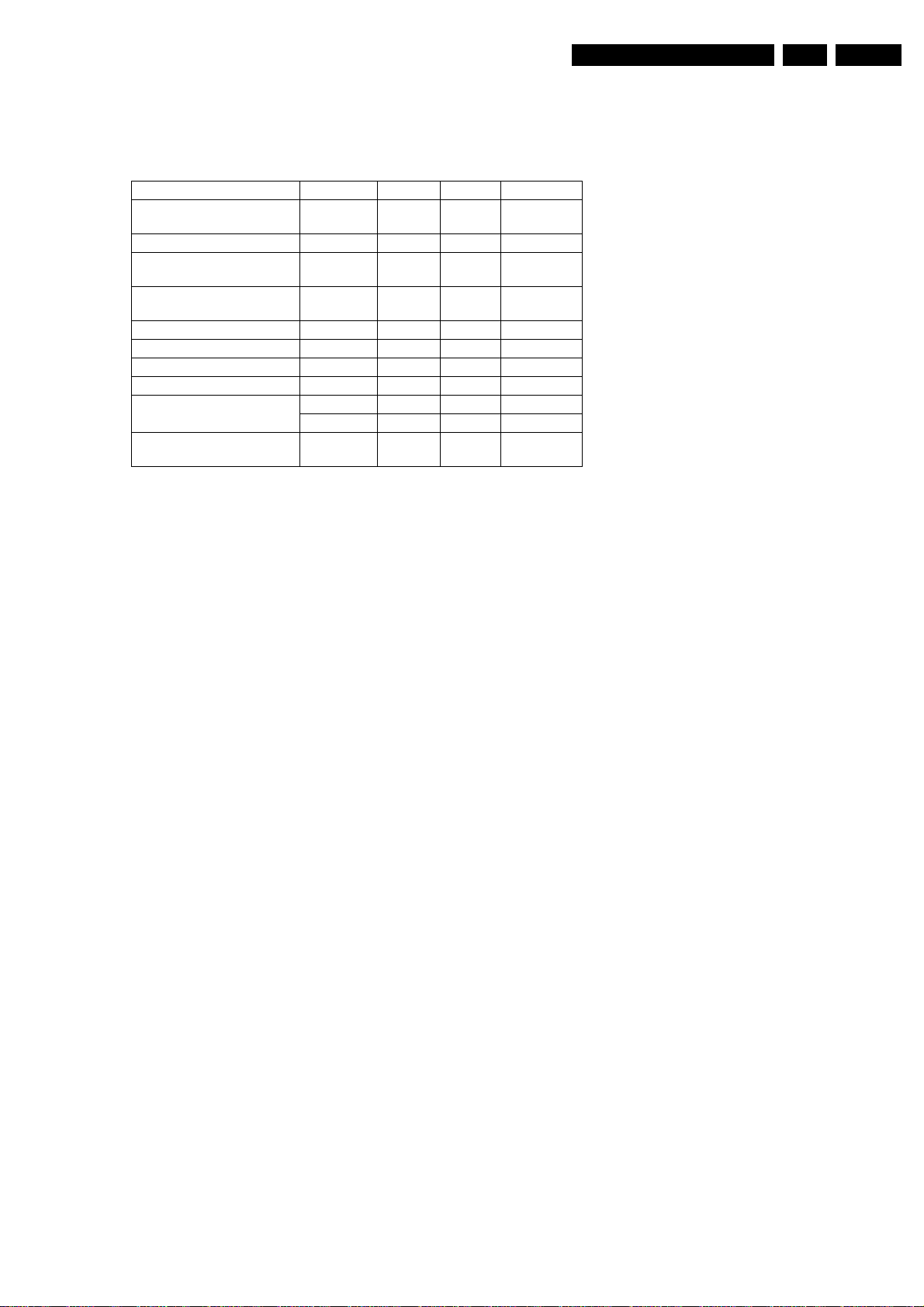
1.1 Diversity Matrix
Type DVDR 80/001 80/021 80/051
Market
Segment/Range
DVIO DVIO 1.8 <VNXY <VNXY <VNXY
Digital Board
(Empress) 1.5
Digital Board
(Chrysalis) 2.1
BE AV2 LF VAE8020/15 X X X
I/O Extension Board CST E1 X X X
EPG Board EU X X X
UP Sub CST E1 X X X
Analog-Board
Display
Control
Remarks:
C Step X X X
E2 <VNXY <VNXY <VNXY
E3 >VNXY >VNXY >VNXY
CST E1 X X
CST E2 X
DC1 CST X X X
EN 3DVDR80/0x1 1.
For Service Manual of Basic Engine VAE8020/15 please refer
to 3122 785 12473.
<VNxy ... The Digital Board Empress 1.5 and the DVIO Board
are used from production start onwards until a certain moment
in time. Then the Digital Board Chrysalis 2.1 is used instead of
the two mentioned boards. With this changeover the production
code "VNxy" that is printed on the type plate of the set will be
changed. At creation date of the service documentation the
production code was not yet known.
1.2 General:
Mains voltage : 198V-276V
Mains frequency : 43 Hz - 63Hz
Power consumption mains : 28 W
Power consumption standby : < 7 W
Power consumption low power
stand-by : < 3 W
1.3 RF Tuner
Test equipment:Fluke 54200 TV Signal generator
Test streams:PAL BG Philips Standard test pattern
1.3.1 System:
PAL B/G, PAL D/K, SECAM L/L’, PAL I
1.3.2 RF - Loop Through:
Frequency range : 45 MHz - 860 MHz
Gain: (ANT IN - ANT OUT) : -6 dB to 0dB
1.3.3 Radio Interference:
input voltage /3 tone method (+40
dB min) : no limit
1.3.4 Receiver:
PLL tuning with AFC for optimum reception
Frequency range: : 45.25 MHz - 857 MHz
Sensitivity at 40 dB S/N : ≥ 60dBµV at 75Ω
(video unweighted )
1.3.5 Video Performance:
Channel 25 / 503,25 MHz,
Test pattern: PAL BG PHILIPS standard test pattern,
RF Level 74 dBV
Measured on SCART 1
Frequency response: : 0 - 4.00 MHz +0-4dB
Group delay ( 0.1 MHz - 4.4 MHz ) : 0 nsec ± 150nsec
1.3.6 Audio Performance:
Audio Performance Analogue - HiFi:
Frequency response at SCART 1
(L+R) output: : 100 Hz - 12 kHz / 0±
3dB
S/N according to DIN 45405, 7, 1967 :
and PHILIPS standard test pattern
video signal: : FM: ≥ 50dB; AM ≥
45dB, unweighted
Harmonic distortion ( 1 kHz, ± 25
kHz deviation ): : FM ≤ 1.5%; AM ≤ 2%
Audio Performance NICAM:
Frequency response at SCART
1(L+R) output: : 40 Hz - 15 kHz 0 ±
3dB
S/N according to DIN 45405, 7, 1967 :
and PHILIPS standard test pattern
video signal: : ≥ 60 dB unweighted
Harmonic distortion (1 kHz): : ≤ 0.5 %
1.3.7 Tuning
Automatic Search Tuning
scanning time without antenna : typ. 3 min. PAL
stop level (vision carrier) : ≥ 37dBµV
Maximum tuning error of a recalled
program : ± 62.5 kHz
Maximum tuning error during
operation : ± 100 kHz
Tuning Principle
automatic B,G, I, DK and L/L’detection
Page 4

EN 4 DVDR80/0x11.
Technical Specifications and Connection Facilities
manual selection in "STORE" mode
1.4 Analogue Inputs
1.4.1 SCART 1 (Connected to TV)
Pin Signals:
1 - Audio R 1.8V RMS
2-Audio R
3 - Audio L 1.8V RMS
4 - Audio GND
5 - Blue/Chroma
GND
6 - Audio L
7 - Blue out/
Chroma in 0.7Vpp ± 0.1V into 75 Ohm (*)
8 - Function
switch <2V = TV
>4.5V / <7V = asp. ratio 16:9 DVD
>9.5V / <12V = asp. ratio 4:3 DVD
9 - Green GND
10 - P50 control
11 - Green 0.7Vpp ± 0.1V into 75 Ohm (*)
12 - Nc
13 - Red/Chroma
GND
14 - fast switch
GND
15 - Red out/
Chroma out 0.7Vpp ± 0.1V into 75 Ohm (*)
± 3dB 0.3Vpp Chroma (burst)
16 - fast switch
RGB/ CVBS or Y <0.4V into 75 Ohm = CVBS
>1V / <3V into 75 Ohm = RGB
17 - Y/CVBS GND
OUT
18 - Y/CVBS GND
IN
19 - CVBS/Y 1Vpp ± 0.1V into 75 Ohm (*)
20 - CVBS/Y
21 - Shield
1.4.2 SCART 2 (Connected to AUX)
Pin Signals:
1 -Audio R 1.8V RMS
2 -Audio R
3 -Audio L 1.8V RMS
4 -Audio GND
5 -Blue/Chroma
GND
6 -Audio L
7-Blue in/
Chroma out ± 3dB 0.3Vpp Chroma (burst)
8 -Function
switch
9 -Green GND
10 -P50 control
11 -Green
12 -Nc
13 -Red/Chroma
GND
14 -fast switch
GND
15 -Red in/
Chroma in
16 -fast switch
RGB/ CVBS or
Y
17 -CVBS GND
OUT
18 -CVBS GND
IN
19 -CVBS/Y/RGB
sync 1Vpp ± 0.1V into 75 Ohm (*)
20 -CVBS/Y
21 -Shield
(*) for 100% white
1.4.3 Audio/Video Front Input Connectors
Audio
Input voltage : 2 Vrms
Input impedance : >10kΩ
Video - Cinch
Input voltage : 1 Vpp ± 3dB
Input impedance : 75 Ω
Video - YC (Hosiden)
Input voltage Y : 1Vpp ± 3dB
Input impedance Y : 75 Ω
Input voltage C : burst 300 mVpp ± 3
dB
Input impedance C : 75 Ω
1.5 Video Performance
All outputs loaded with 75 Ohm
SNR measurements over full bandwidth without weighting.
1.5.1 SCART (RGB)
SNR : > -65 dB on all output
Bandwidth : 4.8 MHz ± 2dB
1.6 Audio Performance CD
1.6.1 Cinch Output Rear
Output voltage 2 channel mode : 2Vrms ± 2dB
Channel unbalance (1kHz) : <1dB
Crosstalk 1kHz : >95dB
Crosstalk 20Hz-20kHz : >85dB
Frequency response 20Hz- 20kHz : ±0.2dB max
Signal to noise ratio : >95 dB
Dynamic range 1kHz : >85dB
Dynamic range 20Hz-20kHz : >80dB
Distortion and noise 1kHz : >85dB
Distortion and noise 20Hz-20kHz : >75dB
Intermodulation distortion : >77dB
Mute : >95dB
Outband attenuation: : >40dB above 30kHz
1.6.2 Scart Audio
Output voltage 2 channel mode : 1.6Vrms ± 2dB
Channel unbalance (1kHz) : <1dB
Crosstalk 1kHz : >85dB
Crosstalk 20Hz-20kHz : >70dB
Frequency response 20Hz- 20kHz : ± 0.2dB max
Signal to noise ratio : >85 dB
Dynamic range 1kHz : >75dB
Dynamic range 20Hz-20kHz : >70dB
Distortion and noise 1kHz : >75dB
Distortion and noise 20Hz-20kHz : >65dB
Intermodulation distortion : >70dB
Mute (spin-up, pause, access) : >85dB
Outband attenuation: : >40dB above 25kHz
Page 5
Technical Specifications and Connection Facilities
EN 5DVDR80/0x1 1.
1.7 Digital Output
1.7.1 Coaxial
CDDA/ LPCM (incl MPEG1) : according IEC958
MPEG2, AC3 audio : according IEC1937
DTS : according IEC1937,
amendment 1
1.8 Digital Video Input (IEEE 1394)
1.8.1 Applicable Standards
Implementation according:
IEEE Std 1394-1995
IEC 61883 - Part 1
IEC 61883 - Part 2 SD-DVCR (02-01-1997)
Specification of consumer use digital VCR’s using 6.3 mm
magnetic tape - dec.1994
Mechanical connection according:
Annex A of 61883-1
1.9 P 50 Sy st em Co ntro l
Via SCART pin nr 10
1.10 Dimensions and Weight
Height of feet : 10mm
Apparatus tray closed : WxDxH :435 x 324.5 x
88cm
Apparatus tray open : WxDxH :435 x 366 x
88cm
Weight without packaging : app. 4 kg ± 0.5 kg
Weight in packaging : app. 6.5 kg
1.11 Laser Output Power & Wavelength
1.11.1 DVD
Output power during reading : 0.8mW
Output power during writing : 20mW
Wavelength : 660nm
1.11.2 CD
Output power : 0.3mW
Wavelength : 780nm
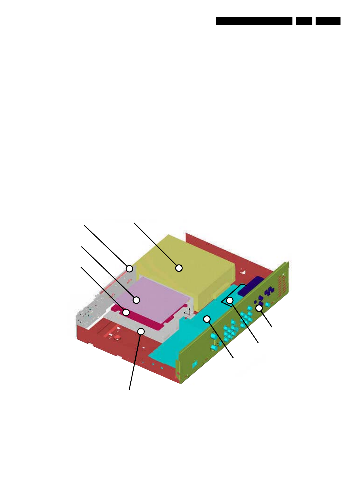
1.12 PCB Locations
Display Board
EPG Board
DVIO Board
Basic Engine
IOE Board
Up Sub Board
Analog Board
Digital Board
TR 06002_001
300103
Page 6
EN 6 DVDR80/0x12.
Safety Information, General Notes
2. Safety Information, General Notes
2.1 Safety Instructions
2.1.1 General Safety
Safety regulations require that during a repair:
• Connect the unit to the mains via an isolation transformer.
• Replace safety components, indicated by the symbol ,
only by components identical to the original ones. Any
other component substitution (other than original type) may
increase risk of fire or electrical shock hazard.
Safety regulations require that after a repair, you must return
the unit in its original condition. Pay, in particular, attention to
the following points:
• Route the wires/cables correctly, and fix them with the
mounted cable clamps.
• Check the insulation of the mains lead for external
damage.
• Check the electrical DC resistance between the mains plug
and the secondary side:
1. Unplug the mains cord, and connect a wire between
the two pins of the mains plug.
2. Set the mains switch to the 'on' position (keep the
mains cord unplugged!).
3. Measure the resistance value between the mains plug
and the front panel, controls, and chassis bottom.
4. Repair or correct unit when the resistance
measurement is less than 1 MΩ.
5. Verify this, before you return the unit to the customer/
user (ref. UL-standard no. 1492).
6. Switch the unit ‘off’, and remove the wire between the
two pins of the mains plug.
2.1.2 Laser Safety
This unit employs a laser. Only qualified service personnel may
remove the cover, or attempt to service this device (due to
possible eye injury).
2.2 Warnings
2.2.1 General
• All ICs and many other semiconductors are susceptible to
electrostatic discharges (ESD, ). Careless handling
during repair can reduce life drastically. Make sure that,
during repair, you are at the same potential as the mass of
the set by a wristband with resistance. Keep components
and tools at this same potential.
Available ESD protection equipment:
– Complete kit ESD3 (small tablemat, wristband,
connection box, extension cable and earth cable) 4822
310 10671.
– Wristband tester 4822 344 13999.
• Be careful during measurements in the live voltage section.
The primary side of the power supply (pos. 1005), including
the heatsink, carries live mains voltage when you connect
the player to the mains (even when the player is 'off'!). It is
possible to touch copper tracks and/or components in this
unshielded primary area, when you service the player.
Service personnel must take precautions to prevent
touching this area or components in this area. A 'lightning
stroke' and a stripe-marked printing on the printed wiring
board, indicate the primary side of the power supply.
• Never replace modules, or components, while the unit is
‘on’.
2.2.2 Laser
• The use of optical instruments with this product, will
increase eye hazard.
• Only qualified service personnel may remove the cover or
attempt to service this device, due to possible eye injury.
• Repair handling should take place as much as possible
with a disc loaded inside the player.
• Text below is placed inside the unit, on the laser cover
shield:
Laser Device Unit
Type : Semiconductor laser
GaAlAs
Wavelength : 650 nm (DVD)
: 780 nm (VCD/CD)
Output Power : 20 mW
(DVD+RW writing)
: 0.8 mW
(DVD reading)
: 0.3 mW
(VCD/CD reading)
Beam divergence : 60 degree
Figure 2-1
Note: Use of controls or adjustments or performance of
procedure other than those specified herein, may result in
hazardous radiation exposure. Avoid direct exposure to beam.
CAUTION VISIBLE AND INVISIBLE LASER RADIATION WHEN OPEN AVOID EXPOSURE TO BEAM
ADVARSEL SYNLIG OG USYNLIG LASERSTRÅLING VED ÅBNING UNDGÅ UDSÆTTELSE FOR STRÅLING
ADVARSEL SYNLIG OG USYNLIG LASERSTRÅLING NÅR DEKSEL ÅPNES UNNGÅ EKSPONERING FOR STRÅLEN
VARNING SYNLIG OCH OSYNLIG LASERSTRÅLNING NÄR DENNA DEL ÄR ÖPPNAD BETRAKTA EJ STRÅLEN
VARO! AVATTAESSA OLET ALTTIINA NÄKYVÄLLE JA NÄKYMÄTTÖMÄLLE LASER SÄTEILYLLE. ÄLÄ KATSO SÄTEESEEN
VORSICHT SICHTBARE UND UNSICHTBARE LASERSTRAHLUNG WENN ABDECKUNG GEÖFFNET NICHT DEM STRAHL AUSSETSEN
DANGER VISIBLE AND INVISIBLE LASER RADIATION WHEN OPEN AVOID DIRECT EXPOSURE TO BEAM
ATTENTION RAYONNEMENT LASER VISIBLE ET INVISIBLE EN CAS D'OUVERTURE EXPOSITION DANGEREUSE AU FAISCEAU
!
Figure 2-2
2.2.3 Notes
Dolby
Manufactered under licence from Dolby Laboratories. “Dolby”,
“Pro Logic” and the double-D symbol are trademarks of Dolby
Laboratories. Confidential Unpublished Works.
©1992-1997 Dolby Laboratories, Inc. All rights reserved.
Figure 2-3
Trusurround
TRUSURROUND, SRS and symbol (fig 2-4) are trademarks of
SRS Labs, Inc. TRUSURROUND technology is manufactured
under licence frm SRS labs, Inc.
Figure 2-4
Page 7

Safety Information, General Notes
Video Plus
“Video Plus+” and “PlusCode” are registered trademarks of the
Gemstar Development Corporation. The “Video Plus+” system
is manufactored under licence from the Gemstar Development
Corporation.
Figure 2-5
Macrovision
This product incorporates copyright protection technology that
is protected by method claims of certain U.S. patents and other
intellectual property rights owned by Macrovision Corporation
and other rights owners.
Use of this copyright protection technology must be autorized
by Macrovision Corporation, and is intended for home and
other limited viewing uses only unless otherwise authorized by
Macrovision Corporation. Reverse engineering or disassembly
is prohibited.
EN 7DVDR80/0x1 2.
Page 8
EN 8 DVDR80/0x13.
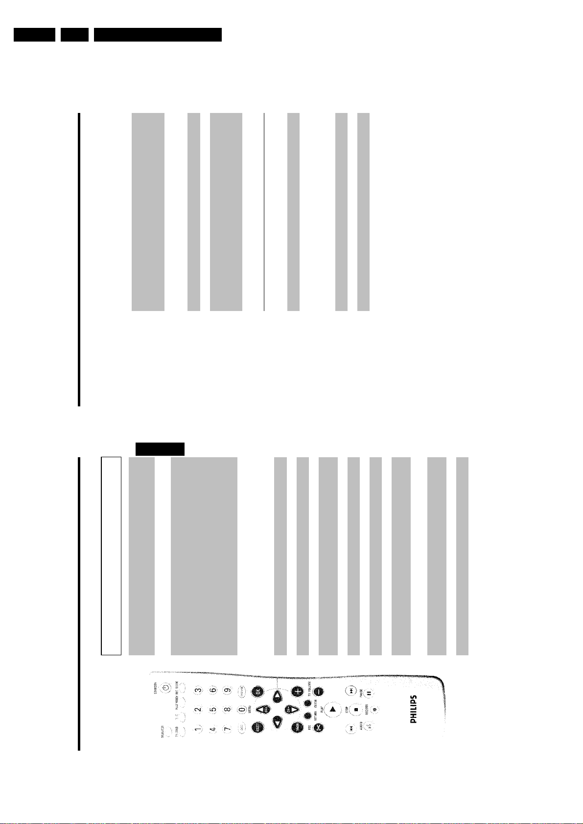
3. Directions For Use
Briefly press the button during playback: Previous chapter/film or
previous title
Hold down the button: Search backwards
Hold down button during still picture, slow motion backwards
Briefly press the button during playback: Next chapter/film or next title
Hold down the button: Search forwards
Hold down button during still picture, slow motion forwards
(TIMER)
N Select previous title/search backwards :
O Select next title/search forwards :
STOP h Stop: Stop playback/recording, except with programmed recordings
Hold down button, opens and closes the disc tray.
Directions For Use
DVD recorder switches to pause. You will see a still picture.
If this button is pressed during recording, the DVD recorder will also
switch to pause.
TV VOLUME q TV volume: Increase TV volume
AUDIO Audio: Select the audio language. For recording language 1 or 2
REC/OTR n Record: Record the current TV channel
PAUSE 9 Pause (still picture): If this button is pressed during playback, the
Additional TV functions
This will only work with TV sets with the same remote control code *RC5) (e.g. Philips TV sets)
TV VOLUME r TV volume: Reduce TV volume
For the following functions you need to hold down the button at the side DVD/TV and then
select the function you need with the appropriate button.
STANDBY m Switching the TV off:
0..9 Number buttons:0-9
CH+ A TV programme number: To select a higher programme number
CH- B TV programme number: To select a lower programme number
tuner) in the DVD recorder (TV picture on the TV set) and playback on
MONITOR Monitor: This button lets you switch between the TV receiver (internal
The remote control
the DVD recorder.
STANDBY m Switch on or off: To switch set on or off, interrupt menu function,
ENGLISH
interrupt a programmed recording (TIMER)
to the TV set. This lets you watch the picture from any unit connected
TV/DVD TV/DVD switch: Switches the scart socket EXT 2 AUX-I/O directly
to this scart socket (set-top box', video recorder or satellite receiver)
and at the same time record from another source.
If you have not connected a device to the EXT 2 AUX-I/O socket, use
this button to switch between TV reception and the DVD recorder.
But this only works if you use a scart cable to connect the TV set to
your DVD recorder ( EXT 1 TO TV-I/O socket) and your TV set
responds to this switch-over.
'(Chapter) directly from the
C
'(Title)/'
B
menu bar
T/C Title/Chapter: Choose the '
/without
®
or to alter or clear a programmed TIMER
®
If 'INFO' appears in the display, the index menu from a recorded disc or
an introductory film will be shown. In this case, this function is not
available.
PLAY MODE Playback type: Choose between repeat, shuffle play and intro-scan
REC MODE Record type (quality): To select the maximum possible record time
the screen)
0..9 Number buttons:0-9
DISC-MENU Disc menu: To show the DVD menu or the index screen
SYSTEM-MENU System menu: Call up/cancel the main menu (menu bar at the top of
SELECT Select: Select function/value
OK Store/confirm: To store or confirm entry
DC Cursor keys : Cursor left, right
CH+ A Cursor buttons/Plus : Cursor up/ Next programme number
CH- B Cursor buttons/Minus : Cursor down / Previous programme number
ShowView
TIMER TIMER: To make a TIMER programming with ShowView
chapter markers
FSS & EDIT: For displaying the edit menu for DVD+R(W) discs, for setting
RETURN Back: Return to previous menu on a video CD (VCD). This also works
with some DVDs.
CLEAR Delete: To delete last entry or clear programmed recording (TIMER)
PLAY G Playback: To play a recorded disc.
Page 9
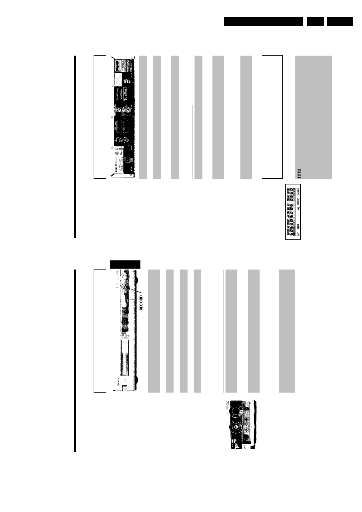
Back of the unit
4MAINS Mains socket: Connection to the mains supply (230V/50Hz)
ANTENNA IN Aerial input: Connection of the aerial
Directions For Use
set-top box, video recorder, camcorder, etc.)
TV OUT Aerial output: Connection of the TV set
EXT 2 AUX-I/O Scart socket 2: Connection of an additional device (satellite receiver,
EXT 1 TO TV-I/O Scart socket 1: Connection of a TV set. RGB output
Output sockets (AUDIO/VIDEO OUT)
EN 9DVDR80/0x1 3.
Multi-function display/text line
•) Clock
•) Disc/title playing time
•) OTR switch-off time
•) Title name
•) Display of the programme number of the TV channel/playing
time/channel name/function.
Video output (yellow socket): Connecting a TV set with a video
input (CVBS, Composite Video)
set with audio input sockets or connection of an additional device
OUT S-VIDEO (Y/C) SVideo output: Connection of an S-Video-compatible TV set
OUT VIDEO
OUT L AUDIO R Analogue audio output (white/red socket): Connection of a TV
(CVBS)
Output socket (DIGITAL AUDIO OUT)
Digital audio output: Connection of a digital audio device
DIGITAL AUDIO
(amplifier/receiver)
OUT
The symbols on your DVD recorder
display
These symbols can light up on your DVD recorder display:
•) Display of information and alerts
Front of the device
ENGLISH
STANDBY/ON m Switch on or off: To switch off or on, interrupt a function, interrupt a
programmed recording (TIMER)
OPEN/CLOSE J Open/close disc tray: Open/close disc tray
RECORD Record: Record the current TV channel
G Playback: To play a recorded disc
N Select previous title/search backwards
O Select next title/search forwards
h Stop: Interrupt playback/recording
Behind the flap at the righthand corner on
S-VIDEO SVideo socket: Connection of SVHS/Hi8 camcorders or SVHS/Hi8
the front
video recorders (programme number 'CAM1')
Video input socket: Connection of camcorders or video recorders
(programme number 'CAM1')
VIDEO
Yellow socket
Audio input socket left/right : Connection of camcorders or video
recorders (programme number 'CAM1')
left AUDIO right
White/red socket
Switching between the S-VIDEO and VIDEO sockets takes place automatically. If both sockets
are in use, the signal at the S-VIDEO socket has priority.
Connecting a digital camcorder or other suitable device (programme
DV IN iLink/DV socket (digital video input, IEEE 1394, FireWire):
number 'CAM2').
Page 10
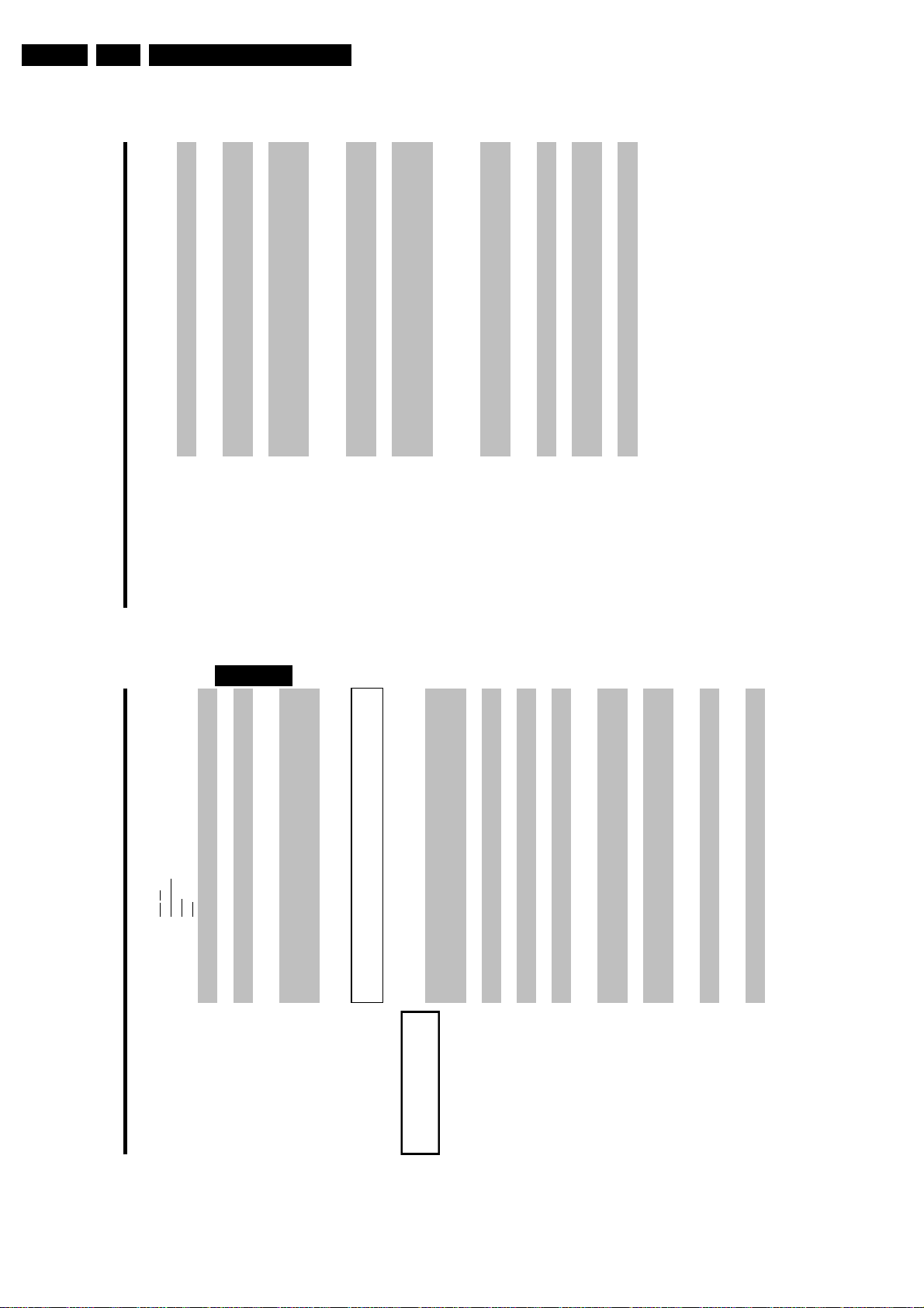
EN 10 DVDR80/0x13.
Directions For Use
recordings).
EMPTYDISC The disc inserted is either new or has been completely erased (no
PROTECTED The disc is protected against recording.
MAX TITLE The maximum number of titles per disc has been reached. The
maximum number of titles per disc is 48.
maximum number of chapters per title is 124.
MAX CHAP The maximum number of chapters per title/disc has been reached. The
DISC FULL The disc is full. There is no space for new recordings
PAL DISC A disc with PAL recordings has been inserted. The machine is trying to
ENGLISH
record an NTSC signal. Insert a new disc or one that contains NTSC
recordings.
NTSC DISC A disc with NTSC recordings has been inserted. The machine is trying
to record a PAL signal. Insert a new disc or one that contains PAL
recordings.
recording.
RECORDING An illegal action (e.g. OPEN/CLOSE J button) was attempted during
FREETITLE Playback was started for an empty title or the following title is empty.
disc. This message appears if an attempt is made to insert a chapter
marker ( FSS & button).
DISC LOCK An attempt has been made to record during playback of a protected
please clean the disc or use a new one.
For instructions on how to clean a disc see the section on 'Cleaning the
DISC ERR An error occurred when writing the title. If this error keeps occurring,
discs' in the next chapter.
DISC WARN An error occurred when writing the title. Recording was continued; the
error was skipped
SETUP After the automatic search the menu for setting the date/time will
appear on the screen.
WAIT 01 During the automatic search the TV channels found are counted
BLOCKED The disc tray cannot be closed/opened.
(SAFE RECORD).
SAFE REC The new recording will be added at the end of all the other recordings
EASYLINK Data is being transferred from the 'EasyLink' TV.
POST-FORMAT Post format
Disc bar: Displays the current position on the disc (disc pointer).
Play/Record: Single flashing segment at the current position.
Pause: Flashing segment on both sides of the current position.
IIIIIIIIIIIIIII
Stop: Illuminated segment at the current position.
A satellite recording has been programmed.
SAT
A recording (timer) has been programmed
A remote control signal has been received
TIMER
o(((
Video programming system / programme delivery control: A VPS or
PDC code will be transmitted for the selected TV program
During playback a HiFi/2 channel tone was detected or a HiFi/2 channel
VPS/PDC
LANG II
tone was received. 'I' or 'II' lights up depending on which sound channel
has been selected
Messages in the DVD recorder display
read the paragraph on 'Initial installation' in 'Installing your DVD
recorder'.
IS TV ON? The DVD recorder is in initial installation mode. Switch the TV on, then
The following messages may appear in your DVD recorder display
READING
NO SIGNAL No input signal available (signal inadequate or unstable)
MENU The menu on the screen is active
OPENING Disc tray opening
TRAY OPEN Disc tray open
CLOSING Disc tray closing
READING Disc being read
MENU UPDT Once recording has been successfully completed the table of contents is
created.
INIT MENU The menu structure is created after the first recording has been made
on a new disc
COPY PROT You have tried to copy a copy-protected DVD/video cassette.
WAIT Please wait until this message disappears. The DVD recorder is busy
performing a task.
cannot be read.
Information about the inserted DVD is displayed on the screen
compatible
NO DISC A disc has not been inserted for recording. If a disc has been inserted, it
INFO
BUSY The DVD recorder is processing the changes to make them DVD
ERASING The entire disc is erased
Page 11
Directions For Use
EN 11DVDR80/0x1 3.
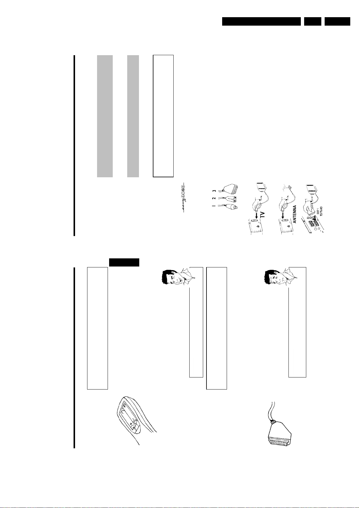
Connecting the DVD recorder
When you install your DVD recorder for the first time, select one of the following options:
'Connecting with a scart cable and Easy Link'
If your TV set is equipped with 'Easy Link, Cinema Link, NexTView Link, Q-Link, Smart Link,
Megalogic, Datalogic, ...' and you wish to use a scart cable.
'Connecting with a scart cable without Easy Link'
If your TV set is not equipped with 'Easy Link, Cinema Link, NexTView Link, Q-Link, Smart Link,
Megalogic, Datalogic, ...' and you wish to use a scart cable.
'Connecting with an SVideo(Y/C)cable'
If your TV set is equipped with an S-Video(SVHS) socket.
'Connecting with video(CVBS) cable'
If your TV set is equipped only with an video(CVBS) socket.
ENGLISH
Connecting with a scart cable and
'Easy Link'
Your DVD recorder can exchange information with your TV set using 'Easy Link'. Your TV
channels can also be transferred in the same order from your TV set to your DVD recorder
using 'Easy Link'.
Please see your TV's operating instructions.
Tip
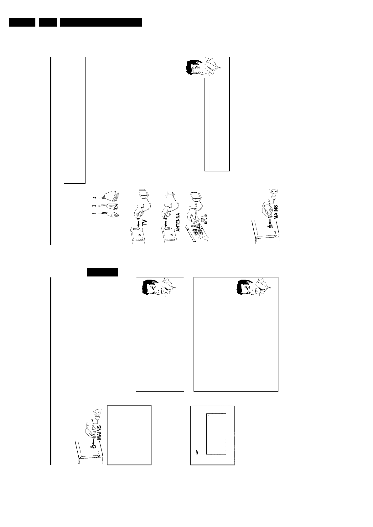
Have the following cables ready:
an aerial cable (1, supplied), a mains cable (2, supplied), a special scart cable (3, suitable for
Easylink).
ANTENNA IN socket at the back of the DVD recorder.
1 Switch off your TV set.
2 Remove the aerial cable plug from your TV set. Insert it into the
the back of the DVD recorder and the other end into the aerial input
socket at the back of the TV set.
3 Insert one end of the supplied aerial cable into the TV OUT socket at
TO TV-I/O at the back of the DVD recorder and the corresponding
scart socket at the back of the TV set (see TV set operating
4 Plug in a special scart cable (for Easylink) into the scart socket EXT 1
instructions).
12
11
?
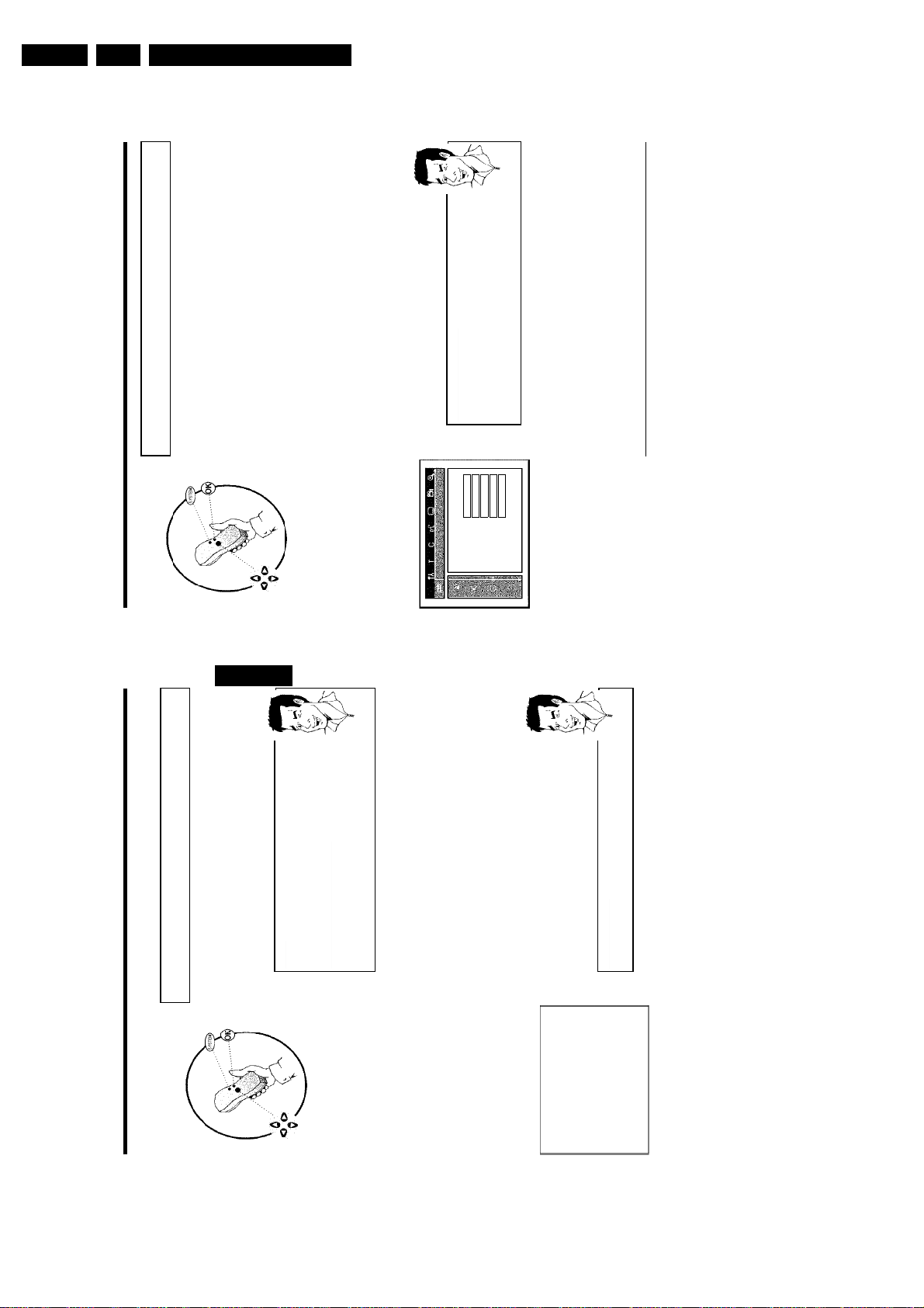
Preparing the remote control for
Connecting the DVD recorder
B
operation
The remote control and its batteries are packed separately in the original DVD recorder
packaging. You must install the batteries in the remote control before use - described in the
following section.
1 Take the remote control and the enclosed batteries (2 batteries).
2 Open the battery compartment, insert the batteries as shown and
then close the battery compartment.
The remote control is now ready to use.
Its range is approximately 5 to 10 meters.
'Aim' correctly
In the following sections, you will need the remote control for the first time.
Aim the remote control at the DVD recorder and not at the TV set.
Connecting your DVD recorder to the TV
set
The necessary cable connections must be made before you can record or playback TV
programmes using your DVD recorder.
Connect the DVD recorder directly to your TV set. If there is a video recorder in between
the picture quality may be poor.
We recommend that you use a scart cable to connect your TV set and DVD recorder.
What is a scart cable?
The scart or Euro AV cable serves as the universal connector for picture,
sound and control signals. With this type of connection, there is practically no
loss of quality in picture or sound transmission.
Connecting the DVD recorder
Page 12
EN 12 DVDR80/0x13.
Connecting with a scart cable without
'Easy Link'
Have the following cables ready:
Directions For Use
?
Connecting the DVD recorder
My TV set has several scart sockets. Which one should I use?
Select the scart socket that is suitable for both video output and for video
input.
My TV set shows me a selection menu for the scart socket
ANTENNA IN socket at the back of the DVD recorder.
an aerial cable (1, supplied), a mains cable (2, supplied), a scart cable (3).
1 Remove the aerial cable plug from your TV set. Insert it into the
the back of the DVD recorder and the other end into the aerial input
socket at the back of the TV set.
2 Insert one end of the supplied aerial cable into the TV OUT socket at
3 Plug a scart cable into the scart socket EXT 1 TO TV-I/O at the
back of the DVD recorder and the scart socket for the DVD
recorder at the back of the TV set (see TV set operating instructions).
Select 'VCR' as tje source for this scart socket.
4MAINS at the back of the DVD recorder and the other end into
the wall socket.
The most important features of the DVD recorder will appear in
scrolling text on the display. After the first installation is completed
4 Switch on the TV set.
5 Insert one end of the supplied mains cable into the mains socket
this function will be switched off. How you switch on this function
again, read in the chapter 'User preferences' in the section 'standby'.
6 Switch on the DVD recorder using STANDBY/ON m .'IS TV ON?'
will appear on the display.
switched to the programme number for the scart socket, e.g. 'EXT',
'0', 'AV', you will see the following picture:
7 If the connection was properly made and your TV was automatically
14
ENGLISH
13
Problem
below the picture)
off
remote control.3Select the next line with CH+ A or CH- B .4Check if the displayed settings for 'Year', 'Month' and 'Date' are
correct.
When all information is correct, save by pressing OK .
5
I can see more installation menus on my TV set
Not all the necessary data has been transferred. Please enter the settings
a
Check if the time in 'Time' is correct.2If required, change the time with the number buttons 0..9 on your
Normally the date and time are taken from the data sent by the TV
channel stored on programme P01. If th aerial signal is too weak or there
is excessive interference, you should set the date and time manually:
a'Time', 'Year', 'Month', 'Date' appears on the TV screen
4MAINS at the back of the DVD recorder and the other end into
the wall socket.
5 Switch on the TV set.
6 Insert one end of the supplied mains cable into the mains socket
7 A message appears on the screen announcing that the transfer has
started. 'EASYLINK' appears on the display during transfer.
The TV set transfers all saved TV channels, in the same order, to the
DVD recorder.
This may take several minutes.
1
by hand as follows. For more information on the various functions see
'Initial installation' in 'Installing your DVD recorder'.
with OK .
Select the desired audio language using CH- B or CH+ A and confirm
1
confirm with OK .
Select the desired subtitle language with CH- B or CH+ A and
Select the desired screen format position using CH- B or CH+ A .
'4:3 letterbox' For a 4:3 TV set; cinema format (black bars above and
2
'4:3 panscan' For a 4:3 TV set; full height format with the sides cut
3
Problem
Confirm with OK .5Select the country of your residence with CH- B or CH+ A .
If your country does not appear, select 'Other'.6Confirm with OK .
'16:9' For a 16:9 TV set
4
Initial installation is now complete.
EasyLink
loading data from TV;
please wait
Virgin mode
English
Audio Language
Español
Français
English
Italiano
Press OK to continue
Connecting the DVD recorder
Page 13
Directions For Use
EN 13DVDR80/0x1 3.
Connecting the DVD recorder
Cinch socket OUT L AUDIO R at the back of the DVD recorder
and the other end into the audio input socket (usually red/white) on
4 Insert one end of the supplied audio (Cinch) cable into the red/white
the TV set (usually labelled 'Audio in' or 'AV in'. See TV operating
instructions).
5 Switch on the TV set. Switch the TV set over to the SVHS input
socket or select the relevant programme number. Please see your
TV's operating instructions for the programme number you need.
4MAINS at the back of the DVD recorder and the other end into
the wall socket.
6 Insert one end of the supplied mains cable into the mains socket
ENGLISH
Problem
The most important features of the DVD recorder will appear in
scrolling text on the display. After the first installation is completed
this function will be switched off. How you switch on this function
again, read in the chapter 'User preferences' in the section 'standby'.
7 Switch on the DVD recorder using STANDBY/ON m . IS TV ON?'
will appear on the display.
Then, read the paragraph on 'Initial installation' in 'Installing your DVD recorder'.
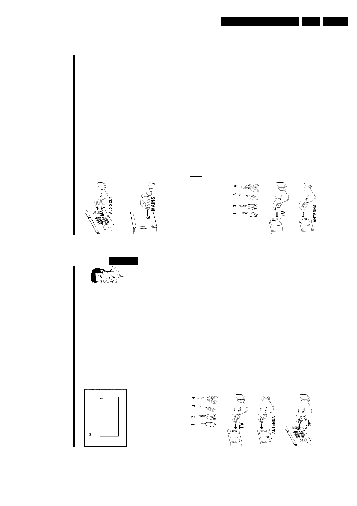
Connecting with video(CVBS) cable
This cable, usually with yellow Cinch connectors, is used for transmitting the Composite Video
signal (FBAS, CVBS). In this method of transmission the colour signal and the brightness signal
are transmitted on the same cable. In certain circumstances, this can lead to problems with the
picturem, such as 'Moiré' patterns.
Have the following cables ready:
an aerial cable (1, supplied), a mains cable (2, supplied), a video (CVBS)cable (3, supplied, yellow
plug), an audio cable (4, supplied, red/white plug).
ANTENNA IN socket at the back of the DVD recorder.
1 Remove the aerial cable plug from your TV set. Insert it into the
the back of the DVD recorder and the other end into the aerial input
socket at the back of the TV set.
2 Insert one end of the supplied aerial cable into the TV OUT socket at
16
15
Virgin mode
aMy screen is empty.
b Many TV sets are switched by the DVD recorder to the programme
Menu Language
number for the scart socket by way of a control signal sent through the
English
scart cable.
b If the TV set does not automatically switch to the scart socket programme
Español
Français
number, manually change to the corresponding programme number on your
TV set (see your TV's operating instructions).
Italiano
Deutsch
Press OK to continue
TO TV-I/O socket on the DVD recorder. The EXT 2 AUX-I/O socket is
intended only for additional devices.
b Check that the scart cable is connected from the TV set to the EXT 1
Connecting with an SVideo(Y/C)cable
Then, read the paragraph on 'Initial installation' in 'Installing your DVD recorder'.
This connecting cable, also known as the SVHS cable, is used to transmit the brightness signal (Y
signal) and colour signal (C signal) separately. This mini DIN socket/plug is also called a Hosiden
socket/plug.
Have the following cables ready:
an aerial cable (1, supplied), a mains cable (2, supplied), an S-Video(SVHS) cable (3), an audio
cable (4, supplied, red/white plug).
ANTENNA IN socket at the back of the DVD recorder.
1 Remove the aerial cable plug from your TV set. Insert it into the
the back of the DVD recorder and the other end into the aerial input
socket at the back of the TV set.
2 Insert one end of the supplied aerial cable into the TV OUT socket at
(Y/C) socket at the back of the DVD recorder and the other end into
the S-Video (SVHS) input socket on the TV set (usually labelled
3 Insert one end of an S-Video(SVHS) cable into the OUT S-VIDEO
'S-Video in' or 'SVHS in'. See TV operating instructions).
Connecting the DVD recorder
Page 14
EN 14 DVDR80/0x13.
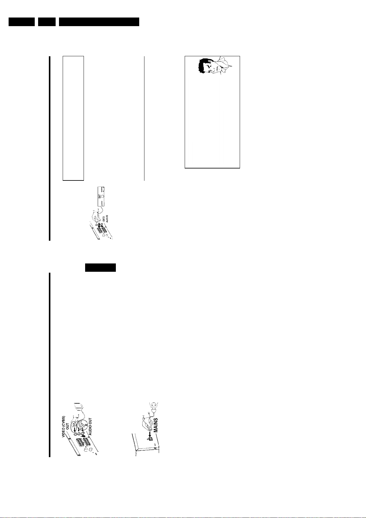
Connecting additional devices to the
second scart socket
You can connect additional devices such as decoders, satellite receivers, camcorders, etc. to the
EXT 2 AUX-I/O socket. When playback is started on this additional device the DVD recorder
automatically connects the EXT 2 AUX-I/O scart socket with the EXT 1 TO TV-I/O scart
Directions For Use
Problem
Connecting additional devices
shows 'NO SIGNAL'
video recorder.
this signal is poor or does not comply with relevant standards.aWhen I copy DVD video discs or prerecorded video cassettes the
picture is fuzzy and the brightness varies
copy-protected. Even though the picture on the TV is fine the recording on
a DVD+R(W) is faulty. This interference is unavoidable with copy-protected
aWhen copying video cassettes the display on the DVD recorder
b Check that the cable is plugged in firmly.
b If a recording is made from a video recorder, change the tracking on the
b The DVD recorder may not be able to recognise the video input signal if
EXT 2 AUX-I/O scart socket and playback from the DVD recorder.
socket. You will then see the picture from the additional device on your TV set, even if the
DVD recorder is switched off.
The TV/DVD button on the remote control allows you to switch between playback through the
Connecting additional video recorders
You can connect a video recorder to the EXT 2 AUX-I/O socket.
If you have an SVHS video recorder you can also use the OUT S-VIDEO (Y/C) socket and the
OUT L AUDIO R sockets.
Please note:
Most prerecorded video cassettes and DVDs are copy-protected. If you try to copy them you
will see the message 'COPY PROT' on the DVD recorder's display.
b This happens if you try to copy DVDs or video cassettes that have been
DVDs or video cassettes.
Connecting additional devices
C
Cinch socket OUT VIDEO (CVBS) at the back of the DVD
3 Insert one end of the supplied video (CVBS) cable into the yellow
recorder and the other end into the video input socket (usually
yellow) on the TV set (usually labelled 'Video in' or 'AV in'. See TV
operating instructions).
Cinch socket OUT L AUDIO R at the back of the DVD recorder
4 Insert one end of the supplied audio (Cinch) cable into the red/white
and the other end into the audio input socket (usually red/white) on
the TV set (usually labelled 'Audio in' or 'AV in'. See TV operating
ENGLISH
instructions).
input socket or select the relevant programme number. Please see
5 Switch on the TV set. Switch the TV set over to the Video/Audio
your TV's operating instructions for the programme number you need.
4MAINS at the back of the DVD recorder and the other end into
6 Insert one end of the supplied mains cable into the mains socket
the wall socket.
The most important features of the DVD recorder will appear in
scrolling text on the display. After the first installation is completed
this function will be switched off. How you switch on this function
again, read in the chapter 'User preferences' in the section 'standby'.
7 Switch on the DVD recorder using STANDBY/ON m .'IS TV ON?'
18
17
will appear on the display.
Then, read the paragraph on 'Initial installation' in 'Installing your DVD recorder'.
Connecting the DVD recorder
Page 15
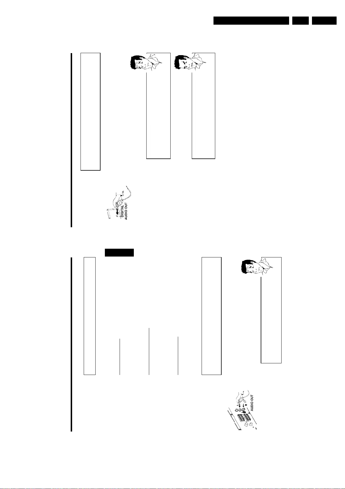
Connecting audio devices to the digital
audio socket
At the back of the DVD recorder there is a digital audio output socket DIGITAL AUDIO
OUT for an coaxial cable.
These can be used to connect the following:
•) an A/V receiver or an A/V amplifier with a digital multichannel sound decoder
•) a receiver with twochannel digital stereo (PCM)
Directions For Use
?
Digital multichannel sound
Digital multi-channel sound offers the best possible sound quality. You will
need a multi-channel A/V receiver or amplifier that supports at least one of
the audio formats of the DVD recorder (MPEG2, Dolby Digital and DTS).
Consult the operating instructions for your receiver to find out which audio
formats it supports.
aAll I can hear from my loudspeakers is a loud distorted noise
b The receiver is not compatible with the digital audio format of the DVD
recorder. The audio format of the DVD disc is displayed in the status
window when you switch to anoter language. Playback in six-channel digital
Problem
surround sound is only possible if the receiver has a digital multi-channel
sound decoder.
EN 15DVDR80/0x1 3.
Connecting additional devices
Connect camcorder to the front sockets
To copy camcorder recordings, you can use the front sockets. These sockets are located behind
the flap on the left hand side.
Best picture quality
If you have a DV or Digital 8 camcorder, connect the DV IN input of the DVD recorder to the
ENGLISH
' function (Subtitle).
E
appropriate DV output on the camcorder.
When films are transferred the original recording date and time are stored as DVD subtitles.
On playback, this data can be displayed on the TV screen by using the '
Very good picture quality
If you have a Hi8 or S-VHS(C) camcorder, connect the S-VIDEO input of the DVD recorder to
the appropriate S-VHS output on the camcorder.
You must also connect the audio input left AUDIO right on the DVD recorder to the audio
output on the camcorder.
Good picture quality
If you have a camcorder that only has a single video output (Composite Video, CVBS), connect
the VIDEO input on the DVD recorder to the appropriate output on the camcorder.
You must also connect the audio input left AUDIO right on the DVD recorder to the audio
output on the camcorder.
Connecting audio devices to the analogue
audio sockets
Two audio output sockets OUT L AUDIO R are located on the back of the DVD recorder
(audio signal output left/right)
These can be used to connect the following:
•) a receiver with Dolby Surround Pro Logic
•) a receiver with twochannel analogue stereo
Can I use the 'Phono' input on my amplifier?
This socket (input) on the amplifier is designed only for record players
without preamplifiers. Do not use this input for connecting the DVD
?
recorder.
The DVD recorder or the amplifier may be damaged as a result.
20
19
Connecting additional devices
Page 16
EN 16 DVDR80/0x13.
Directions For Use
7 Select the desired screen format position using CH- B or CH+ A .
These settings will only be used if you insert a DVD that contains this
information.
Virgin mode
TV Shape
Which screen formats can I select?
4:3 letterbox
4:3 panscan
?
?
Problem
Installing your DVD recorder
the top and bottom.
The DVD recorder cannot find any TV stations
TV set?
If not, check the cable connection from the aerial (aerial socket) to the
DVD recorder and to the TV set.
The DVD recorder searches the entire frequency range in order to find
and save the largest possible number of TV channels.
to the end and then, if you wish, start the automatic search (see 'Automatic
Please wait
b If you have not connected an aerial, go through all the basic settings right
TV station search').
complete' will appear on the TV screen.
B When the automatic TV channel search is complete, 'Autom. search
'Time', 'Year', 'Month', 'Date' will then appear on the TV screen.
C Check if the time in 'Time' is correct.
Autom. search
À If required, change the time with the number buttons 0..9 on your
Autom. search complete
remote control.
00 Channels found
Á Select the next line with CH+ A or CH- B .
Time 20:01
Year 2003
To continue
Press OK
Month 01
Date 01
'4:3 letterbox' for a 'wide-screen' (cinema format) picture with black bars at
'4:3 panscan' for a full-height picture with the sides trimmed.
'16:9' for a wide-screen TV set (screen edge ratio 16:9)
8 Confirm with OK .
16:9
Press OK to continue
Why do I have to select a country?
To call up the specific settings for the respective country, you must first install
Austria
Country
the country.
Belgium
Denmark
Finland
France
Press OK to continue
the DVD recorder, press OK .
0 Confirm with OK .
A After you connect the aerial (or cable TV, satellite receiver, etc.) to
If your country does not appear, select 'Other'.
9 Select the country of your residence with CH- B or CH+ A .
Virgin mode
The automatic TV channel search starts. 'WAIT' will appear on the
display.
a
b Select channel 1 on the TV set. Can you see the stored TV channel on the
Autom. search
Installation
Searching for TV channels
00 Channels found
b Please have patience.
22
Initial installation
Installing your DVD recorder
After successfully connecting your DVD recorder to the TV set and other additional devices as
described in the previous chapters, this chapter will show you how to start the initial installation.
The DVD recorder automatically seeks out and stores all available TV channels.
Connecting additional devices
If you have connected additional devices such as a satellite receiver to the
ENGLISH
aerial cable, switch them on. The automatic channel search will recognise it
and save it.
No aerial connected
Even if you only want to use the DVD recorder to play back or have only
connected a satellite receiver, you must still complete the initial installation.
This is necessary so that the basic settings are stored correctly. Once initial
Tip
installation is complete you can use the DVD recorder as normal.
CH- B or CH+ A .
1 Select the desired language for the on-screen menu by pressing
Virgin mode
What is an onscreen menu?
English
Menu Language
The multi-language on-screen menu takes the mystery out of using your new
Español
Français
?
DVD recorder. All settings and/or functions are displayed on your TV screen
Italiano
in the relevant language.
Deutsch
Press OK to continue
21
?
What is an audio language?
The DVD will play the sound in the language you select, provided this
language is available on the disc. If it is not available on the disc the fist
language on the DVD will be used instead. The DVD Video Disc menu, if
available, will also be displayed in the language you select.
2 Confirm with OK .
3 Select the desired audio language using CH- B or CH+ A .
Virgin mode
English
Español
Français
English
Audio Language
Italiano
Press OK to continue
CH+ A .
4 Confirm with OK .
5 Select the desired language for the subtitles by pressing CH- B or
Virgin mode
What is the subtitle language?
English
Subtitle Language
The subtitles will be displayed in the language you select, provided this
Español
Français
language is available on the disc. If it is not available on the disc the fist
?
language on the DVD will be used instead.
English
Italiano
6 Confirm with OK .
Press OK to continue
D
Installing your DVD recorder
Page 17
Directions For Use
EN 17DVDR80/0x1 3.
Allocating a decoder
Some TV channels send coded TV signals that can only be viewed properly with a purchased or
rented decoder. You can connect such a decoder (descrambler) to your DVD recorder. The
following function automatically activates the connected decoder for the TV channel you want to
watch.
How do I allocate the decoder for Easy Link?
?
?
Installing your DVD recorder
' symbol with D or C .
A
If your TC=V set supports 'Easy Link' the decoder must be assigned to the
relevant TV channel on the TV set (see the operating instructions for your TV
set). Settings cannot then be made in this menu.
the DVD recorder.
1 Switch on the TV set. If required, select the programme number for
0..9 on the remote control to select the TV channel for which you
want to use the decoder. If necessary, use the MONITOR button to
switch to the internal tuner.
bar appears.
3 Use the CH+ A and CH- B buttons or the number buttons
2 Switch on the DVD recorder using STANDBY/ON m .
4 Press the SYSTEM-MENU button on the remote control. The menu
5 Select '
C .
6 Select 'Installation' using CH- B or CH+ A and confirm with C .
7 Select 'Manual search' using CH- B or CH+ A and confirm with
8 Select 'Decoder' using CH- B or CH+ A .
Installation
Manual search
How do I switch the decoder off again?
Use C to select 'Off'inthe'Decoder' line on the screen (Decoder off).
9 Select 'On' with D or C .
Channel/freq. CH
Entry/search 01
0 Confirm with OK .
A To end, press SYSTEM-MENU .
Your decoder has now been allocated to this TV channel.
To store
Press OK
Programme number 01
TV channel name BBC1
Decoder Off
TV system PAL-BG
NICAM On
Fine tuning 0
24
 Check if the displayed settings for 'Year', 'Month' and 'Date' are
correct.
ENGLISH
23
Tip
Satellite receiver
If you are connecting a satellite receiver, please read the section on 'Using a
satellite receiver'.
Decoder
If you are connecting a decoder, you must install it as described in the next
section.
à When all information is correct, save by pressing OK .
The initial installation is now complete.
sound at all, the wrong TV system may have been stored for the TV
aSound may be distorted on some TV channels.
b If the sound is distorted on any of the stored TV channels or if there is no
Problem
channel. Read 'Manual TV channel search' for information on how to
change the TV system.
Using a satellite receiver
TV channels from a satellite receiver (connected to scart socket EXT 2 AUX-I/O ) are received
on the DVD recorder on programme number 'EXT2'
If necessary, use the MONITOR button to switch to the internal tuner.
Select programme number 'EXT1' with 0 on the remote control and then select programme
number 'EXT2' with CH- B .
You should select the TV channels to be received by the satellite receiver directly on the
receiver itself.
Installing your DVD recorder
Page 18
EN 18 DVDR80/0x13.
Directions For Use
In 'TV channel name', press C .2Select the desired symbol position using D or C .3Change the symbol at the symbol position with CH- B or CH+ A .4Select the next symbol position in the same way.5Keep pressing C until the cursor disappears.
How can I change the symbol of a TV channel?
1
Tip
How can I change the TV system of the TV channel?
In 'TV system', use D or C to select the TV system that produces the
least distortion of picture and sound.
What is NICAM?
NICAM is a digital sound transmission system. Using NICAM, you can
Tip
.
8
?
Installing your DVD recorder
transmit either 1 stereo channel or 2 separate mono channels. However, if
reception is poor and the sound distorted you can turn off NICAM.
In 'NICAM', select 'Off' using D or C .
How can I improve the automatic process for storing channels?
To change the automatic process for storing channels (fine tuning), select
'Fine tuning'.
Using D or C you can try to fine-tune the TV channelmanually.
0 Press OK to store the TV channel.
Sorting TV channels automatically
B To end, press SYSTEM-MENU .
A To search for other TV channels, begin again at
(Follow TV)
When the automatic channel search function is activated, the TV channels are stored in a specific
order. This may differ from the order in which the TV channels appear on your TV set.
This function changes the order of the TV channels stored in your DVD recorder to match the
order on the TV set.
This only works if the DVD recorder ( EXT 1 TO TV-I/O socket) and the TV set are
connected with a scart cable.
What does EasyLink do?
If your TV set supports 'Easylink,..', TV channels will be stored during initial
installation in the same order as they appear on the TV set. To store the TV
channels in a different order, you'll need to change the order on the TV set.
When you start the Follow TV function the information is transferred again
from the TV set.
the DVD recorder.
1 Switch on the TV set. If required, select the programme number for
26
Manual TV channel search
In some cases, not all of the available TV channels may have been found and stored during initial
installation. In this case, you will need to search for and store the missing or coded TV channels
manually.
ENGLISH
Manual search with EasyLink
With 'Easy Link', the DVD recorder will automatically download the TV
channels stored on the TV set. This is why some lines have no function. To
store new TV channels, they must first be stored on the TV set. The
Tip
information will then be transferred to the DVD recorder automatically.
1 Switch on the TV set. If required, select the programme number for
the DVD recorder.
2 Switch on the DVD recorder using STANDBY/ON m .
3 Press SYSTEM-MENU on the remote control. The menu bar
appears.
25
Problem
' symbol with D or C .
A
C .
'Freq.'(Frequency), 'CH'(Channel), 'S-CH'(Special/hyperband channel)
using the number buttons 0..9 .
4 Select '
5 Select 'Installation' using CH- B or CH+ A and confirm with C .
6 Select 'Manual search' using CH- B or CH+ A and confirm with
7 In 'Channel/freq.', select the desired display using C .
Manual search
Installation
8 In 'Entry/search', enter the frequency or channel of the TV station
Channel/freq. CH
Entry/search 01
Programme number 01
TV channel name BBC1
Decoder Off
aI don't know the channel for my TV station
TV system PAL-BG
NICAM On
number/frequency number will appear on the TV screen.
b In this case, press C to start the automatic search. A changing channel
To store
Fine tuning 0
Continue the automatic search until you have found the TV channel you
are looking for.
number you want to use for the TV channel, e.g. '01'.
9 Using D or C in 'Programme number', select the programme
Press OK
Installing your DVD recorder
Page 19
Directions For Use
EN 19DVDR80/0x1 3.
?
Installing your DVD recorder
' symbol with D or C .
A
What does Easy Link do?
With Easylink, you can search for and store TV channels only on the TV set.
These settings are accepted by the DVD recorder. Use this function to start
the transfer of TV channels from the TV set.
the DVD recorder.
appears.
recorder to save all available TV channels. This procedure may take
several minutes.
complete' will appear on the TV screen.
Automatic TV channel search
During installation, all available TV channels are searched for and stored. If the channel
' symbol with D or C .
A
bar appears.
assignments of your cable or satellite TV provider change or if you are reinstalling the DVD
recorder, e.g. after moving house, you can start this procedure again. This will replace the stored
TV channels with the new ones.
the C button.
ENGLISH
the DVD recorder display.
aI cannot switch my TV set to programme number '1'
please disconnect these devices. Other connected devices may have
b If you have connected additional devices to the EXT 2 AUX-I/O socket,
1 Switch on the TV set. If required, select the programme number for
Problem
switched the TV set to the programme number of the scart socket.
2 Switch on the DVD recorder using STANDBY/ON m .
'WAIT' will appear in the display. The DVD recorder compares the TV
3 Press SYSTEM-MENU on the remote control. The menu bar
channels on the TV set and the DVD recorder.
If the DVD recorder finds the same TV channel as on the TV set it
stores it at 'P01'.
4 Select '
5 Select 'Installation' using CH- B or CH+ A and confirm with C .
6 Select 'Autom. search' using CH- B or CH+ A .
7 Press C .
8 The automatic TV channel search starts. This allows the DVD
9 When all the TV channels have been found, 'Autom. search
Autom. search
Installation
Searching for TV channels
00 Channels found
0 To end, press SYSTEM-MENU .
Please wait
You can read about how to search for a TV channel manually in 'Manual TV channel search'.
28
27
Problem
receiving a video signal from the TV set.
for video signals.
b Chech the connectors at both ends of the scart cable.
b Check your TV's operating instructions to see which scart socket is used
b If the problem persists, you won't be able to use this feature.
Please read 'Adding and clearing TV channels manually'.
a'NOTV' will appear in the display. The DVD recorder is not
Tip
Deleting sorting
You can delete incorrect TV channel sorting by pressing D .
until you have assigned all the TV channels.
B
to
0
3 Press the SYSTEM-MENU button on the remote control. The menu
2 Switch on the DVD recorder using STANDBY/ON m .
5 Select 'Installation' using CH- B or CH+ A and confirm with C .
4 Select '
6 Select line 'Follow TV' with CH- B or CH+ A . and confirm with
7 Confirm the message on the screen with OK .'TV 01' will appear in
8 Select programme number '1' on the TV set.
TV 01
9 Confirm with OK on the DVD recorder remote control.
0 Wait until for example 'TV 02' appears in the display.
A Select the next programme number on the TV set, e.g. '2'.
B Confirm with OK on the DVD recorder remote control.
TV 02
C Repeat steps
À To end, press SYSTEM-MENU .
Installing your DVD recorder
Page 20
EN 20 DVDR80/0x13.
the DVD recorder.
Directions For Use
' symbol with D or C .
A
appears.
the C button.
Which settings can I choose?
'Audio Language' : Playback language (audio language)
'Recording audio' : Type of audio recording 'Language 1'or'Language2''Subtitle' : Subtitle language
'Menu': Language of the OSD menu
Tip
'Country' : Location (country)
Installing your DVD recorder
with OK .
Setting the language/country
You can select the country and, for DVD playback, the language for the subtitles and the audio
language. Please note that with some DVDs the audio language and/or subtitle language can be
changed only via the DVD menu.
For bilingual shows you can also select the sound channel of the TV station for recording.
You also have the option of setting one of the displayed languages for the on-screen menu
(OSD). However, the DVD recorder display will only display English text regardless of this
setting.
1 Switch on the TV set. If required, select the programme number for
ENGLISH
EasyLink
With Easylink, you can search for and store TV channels only on the TV set.
2 Switch on the DVD recorder using STANDBY/ON m .
These settings are then accepted by the DVD recorder.
That is why you cannot select this function manually.
3 Press SYSTEM-MENU on the remote control. The menu bar
The teletext clock resets automatically
If you store a TV channel which transmits TXT/PDC on programme number
'P01', the date and time will automatically be transmitted and constantly
updated. As a result, the changes from summer time to winter time and back
5 Select line 'Language' with CH- B or CH+ A . and confirm with
4 Select '
Tip
again will be made automatically.
6 Select the appropriate line and confirm with C .
the DVD recorder.
Language
the remote control. The menu bar appears.
Audio Language English
' symbol with D or C .
A
7 Select the appropriate setting using CH- B or CH+ A and confirm
8 To end, press SYSTEM-MENU .
Switching over audio recording
(2channel sound)
Some TV programmes transmit an extra audio signal in stereo in addition to the normal audio
signal (2-channel sound). In most cases this means that an additional language is available. If a TV
programme is available in, say, English and German, German may be available as the second
language.
To record TV programmes in stereo or 2-channel sound you can select Stereo or the language
you want as the default setting. This setting does not become active until the sound of a TV
programme is transmitted in 2-channel sound.
When you play back the recording you can play back the sound only in the language you used
for the recording.
Recording audio Language 1
Subtitle English
Menu English
Country Other
30
29
Tip
until you have resorted/deleted all the TV
8
to
6
CLEAR . Proceed at step 6 .
Deleting TV channels
with C .
delete or whose order you want to change.
Unwanted channels or those with poor reception can be deleted using
position and press the D button. The DVD recorder will insert the
TV channel.
channels you want.
Adding and clearing TV channels manually
After you have performed the automatic channel search you may not agree with the sequence in
which the individual TV channels have been allocated to the programme positions (programme
numbers). You can use this function to rearrange the TV channels already stored or to delete
TV channels you don't want or those with poor reception.
4 Select 'Installation' using CH- B or CH+ A and confirm with C .
1 Switch on the TV set. If required, select the programme number for
2 Switch on the DVD recorder. Press the SYSTEM-MENU button on
5 Select 'Sort TV channels' using CH- B or CH+ A and confirm
6 Using CH- B or CH+ A select the TV channel that you want to
...
Sort TV channels
Installation
7 Confirm with C .
• P01 BBC1
P02 BBC2
To exit press
SYSTEM MENU
P03 ITV
P04
P05
P06
...
To sort
Press ›
3 Select '
8 Using CH- B or CH+ A , shift the TV channel to the desired
9 Repeat steps
0 To store, press OK .
A To end, press SYSTEM-MENU .
Installing your DVD recorder
Page 21
Directions For Use
User preferences
Title/trackCChapter/index
Audio languageESubtitle languageFCamera angleGZoom
EN 21DVDR80/0x1 3.
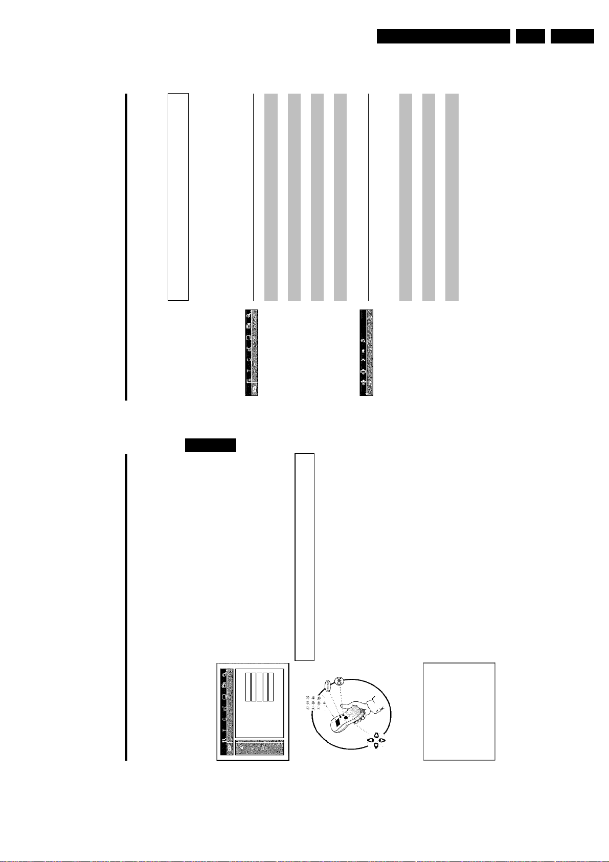
On-screen information
SoundIFrame advanceJSlow motionKFast forwardLSearch by time
system menu bar. The menu bar cannot be displayed during recording.
Symbols in the menu bar
You can check or change many of the functions and settings of your DVD recorder via the
Onscreen information
E
Press SYSTEM-MENU to open and close the menu bar (main menu). Use D and C to select
the relevant function. Use CH- B to confirm the function and go either to another menu or
execute the function directly.
Some functions may not be available, depending on the disc inserted.
ENGLISH
A
B
Menu bar 1
D
Menu bar 2
While menu bar 1 is being displayed you can go to menu bar 2 by pressing C again.
H
32
31
the DVD recorder.
1 Switch on the TV set. If required, select the programme number for
' symbol with D or C .
A
6 Select line 'Recording audio' and confirm with C .
Language
Audio Language English
7 Select 'Language 1'or'Language 2' with CH- B or CH+ A and
Recording audio Language 1
confirm with OK .
Subtitle English
Menu English
Country Other
8 To end, press SYSTEM-MENU .
Setting the time and date
If the display shows an incorrect time or '--:--', the time and date must be reset manually.
If a TV channel which transmits TXT/PDC (teletext/PDC) is stored under programme number
'P01', the time and date will automatically be taken from the TXT/PDC information.
appears.
3 Press SYSTEM-MENU on the remote control. The menu bar
2 Switch on the DVD recorder using STANDBY/ON m .
the C button.
4 Select '
5 Select line 'Language' with CH- B or CH+ A . and confirm with
1 Press SYSTEM-MENU on the remote control. The menu bar
appears.
' symbol with D or C .
A
'Stored' will appear briefly on the screen.
the fields, use CH- B or CH+ A .
with the number buttons 0..9 on your remote control.
7 Check the displayed settings and confirm with OK .
3 Select 'Installation' using CH- B or CH+ A and confirm with C .
4 Select 'Time/Date' using CH- B or CH+ A and confirm with C .
2 Select '
5 Check if the time in 'Time' is correct. If required, change the time
Time/Date
Installation
6 Check 'Year', 'Month' and 'Date' in the same way. To move between
Time 20:00
Year 2003
Month 01
8 To end, press SYSTEM-MENU .
To exit press
SYSTEM MENU
Date 01
Installing your DVD recorder
Page 22
EN 22 DVDR80/0x13.
Directions For Use
On-screen information
RecordingSStopTPlaybackUPlaybackPause
R
Operating mode symbols
RecordPause
Search forwards (8x speed)YSearch backwards (8x speed)ZSlow motion
V
X
ENGLISH
Tuner information box
This field is located in the bottom left-hand corner of the screen. The aerial signal, the TV
channel and the TV channel name for the selected programme are displayed.
Current channel/selected input socketbNo signal
The TV channel is not available/the additional device is not connected or
a
it is switched offcCopyprotected signal
Timer information box
This box appears above the tuner information box. When a timer recording is set, it shows the
timer icon and the start time or date of the first programme to be recorded.
If no timer recording is scheduled, the current time is displayed.
This box disappears during playback of a disc or after a recording starts.
Timer starts on the day showngOTR recording runs until the stop time displayedhCurrent time
f
No timer event programmed
34
33
Field for temporary messages
The top left corner of the menu line contains a field for temporary messages relating to the
various operating modes. This information appears briefly on the screen when certain disc
functions have been activated:
ShuffleScanRepeat entire discRepeat titleRepeat trackRepeat chapterRepeat from A to the endRepeat from A to BCamera angleChild lock enabledResume playbackIllegal action
Status field
The status field shows the current operating mode (status) of the DVD recorder and the type of
disc inserted. This display can be disabled.
DVD+RWWDVD+RNDVDVideo
M
Disc type symbols
VideoCDPNo discQError
O
On-screen information
Page 23
Directions For Use
EN 23DVDR80/0x1 3.
Opening/closing the tray using the remote control
You can open and close the disc tray using the remote control.
Press and hold the STOP h button on the remote control until the dialog
Tip
box shows 'OPENING'or'CLOSING'.
3 Playback starts automatically.
A menu may appear when a DVD is played back. If the titles and chapters are numbered, press a
playback
This will appear on the display:
title, chapter, elapsed time.
Playing a DVD video disc
1 If playback does not start automatically, press PLAY G .
CH- B buttons or number buttons 0..9 to select a menu item and confirm with OK .
number button on the remote control. You can also use the D , C , CH+ A ,
You can also access the menu using DISC-MENU on the remote control.
For further information see 'Playing a DVD video disc'.
O select the title you want to play back.
When a DVD+RW is played back the index overview appears. Using CH- B , CH+ A , N ,
Confirm with OK .
For further information see 'Playing back a DVD+RW/+R Disc'.
If playback does not start automatically, press PLAY G .
For further information see ' Playing an audio CD'.
If the 'h' symbol appears in the display, start playback by pressing PLAY G .
If a menu appears on the screen, use the remote control buttons indicated on the screen to select
the menu option you want (PREV= N , NEXT= O ) or with the number buttons 0..9 .
For further information see ' Playing a (Super) Video CD'.
2 To stop playback, press STOP h on the remote control or h on
the DVD recorder.
recorder.
3 To eject the disc, press OPEN/CLOSE J on the front of the DVD
C01 2:04
36
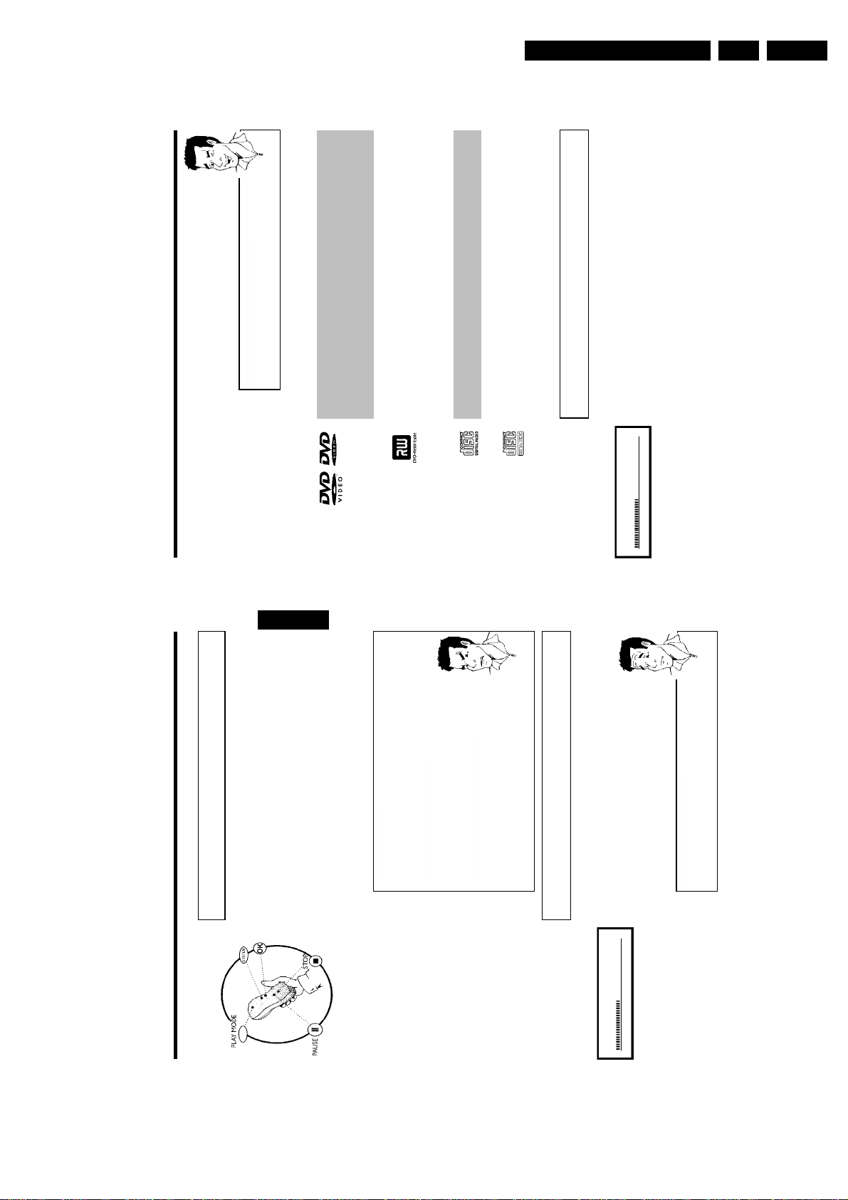
General notes on playback
playback
With this DVD recorder you can play back the following systems:
•) DVD Video
•) (Super)Video CD Disc
•) DVD+RW Disc
•) DVD+R Disc
•) DVD-RW (video mode, finalised)
•) DVD-R
ENGLISH
•) CD-R
•) CD-RW
•) Audio CD
•) MP3 CD
You can operate the video recorder using the remote control or the buttons on the front of the
DVD recorder.
aThe display will read 'PIN'
on 'Child lock' and 'Releasing a disc' in the chapter on 'Access control
b The child lock has been activated for the inserted disc. Read the sections
(child lock).aThe menu on the screen is showing an 'X'
before the disc can be played, or so that only limited operation is possible
b Some DVD discs can be manufactured so that certain steps are required
during playback. When an 'X' appears on the screen the selected feature is
not possible.aThe screen is showing regional code information
b Since DVD films are not normally released in all parts of the world at the
same time, all DVD players have a specific regional code. Discs can be given
a regional code. If the regional codes differ between the player and the
disc, playback is not possible.
b The regional code is shown on the label on the back of the machine.
Problem
b The regional code does not apply to recordable DVD discs.
Inserting a disc
35
?
How do I insert a doublesided DVD?
Double-sided discs do not have labelling over the whole surface. The labelling
for each side is in the centre of the disc. To play a side its label must be
PLAY G or OPEN/CLOSE J .'CLOSING' and then 'READING' will
open. While the disc tray is opening, 'OPENING' and then 'TRAY OPEN'
when the tray is fully open.
appear in the display. The information on the disc will be read.
1 Press the OPEN/CLOSE J button on the front. The disc tray will
2 Carefully place the disc in the tray with the label facing up and press
facing up.
F
OPENING P01
playback
Page 24
EN 24 DVDR80/0x13.
Directions For Use
Playing an MP3 CD
MP3 (MPEG1 Audio Layer-3) files are highly compressed music files. Using this technology the
data volume can be compressed by a factor of 10. This means it is possible to record 10 hours
of music in CD quality on a single CD-ROM.
When creating MP3 CDs please note the following:
File system: ISO9660
Directory structure: maximum of 8 levels
Formats: *.mp3
Filenames: maximum of 12 characters (8+3)
Maximum of 32 albums, 999 titles
Supported sampling frequencies: 32, 44.1, 48 (kHz). Music with sampling frequencies other than
these will be skipped.
Supported bit rates: 32, 64, 96, 128, 192, 256 (kbit/s)
Tip
show on the TV screen and on the display.
Further information on the album, track and artist will also be displayed if
show on the TV screen and on the recorder display.
During stopped playback ( STOP h button) the numbers of the albums will
included in the ID tag.
2 Stop playback using STOP h . The number of albums is displayed in
the display.
Additional playback features
Using N or O select the next or previous title.
You can also use the T/C button to select titles and albums.
MP3 CD display
If the TV is on, the MP3 CD screen appears automatically.
During playback, the current track number and its elapsed playing time will
Important notes for playback:
Only the first session of a multi-session CD will play back.
1 Insert an MP3 CD. Playback starts automatically.
ID3 Tag: Version 1, 1.1. In later versions the directory name is displayed as the album and the
filename as the title.
Tip
the remote control to select the number of the title/chapter.
Press the T/C button and use the C or D button to select the 'T'
symbol for title or 'C' for chapter.2Use the CH- B or CH+ A buttons or the number buttons 0..9 on
1
You can also use the repeat functions ( PLAY MODE button).
playback
38
Playing a DVD+RW/ +R disc
starts automatically.
1 If the disc is write-protected or a finalised DVD+R disc, playback
2 If playback does not start automatically, use the CH- B or
ENGLISH
CH+ A button to select the title you want to play on the index
screen.
You can also use the N or O button on the front.
This will appear on the display:
3 Press the PLAY G button.
title number, recording quality.
Problem
aI can see the message 'EMPTYDISC'
b The disc does not contain any recordings.
the DVD recorder.
4 To stop playback, press STOP h on the remote control or h on
5 To eject the disc, press OPEN/CLOSE J on the front of the DVD
recorder.
What should I note when playing back different recording types
(qualities)?
?
be selected during playback.
For more information see the section on 'Selecting the recording type
(quality)' in the chapter on 'Manual recording'.
The correct recording quality 'M1, M2, M2x, M3, M4, M6' will automatically
Playing an audio CD
You can also use the DVD recorder to play audio CDs
Audio CD display'
1 Insert an audio CD. Playback starts automatically.
Tip
If the TV is on, the audio CD screen appears automatically.
During playback, the current track number and its elapsed playing time will
show on the TV screen and on the recorder display.
37
time are displayed.
2 Stop playback using STOP h . The number of tracks and the total
C01 ANNA P01
playback
Page 25
Directions For Use
EN 25DVDR80/0x1 3.
Changing to another title/chapter
Additonal playback features
G
If there is more than one title or chapter on a disc you can change to another title or chapter
as follows. However if there are several chapters within a title, these will be selected. The title
can then still be selected via the menu bar.
1 During playback, press O to go to the next title/chapter. Press
N to return to the start of the current title/chapter. Press
N twice to return to the start of the previous title/chapter.
Use the T/C (title/chapter) button
Tip
Tip
Problem
Additonal playback features
').
K
' symbol using C or D and confirm with CH- B .
K
appropriate title.
Make sure the symbol 'T' (title) is selected in the menu bar.
Press T/C (title/chapter) and then use CH+ A or CH- B to select the
Use T/C to select chapters within a title. Press T/C and use C to
select the 'C' symbol (chapter).
1
Now select the appropriate chapter with CH+ A or CH- B .
2
Searching a disc
You can search the disc for a recording at 4x, 8x or 32x playback speed. Other speeds can only
be selected via the menu bar ('
1 During playback, press and hold N (reverse) or O (forwards) to
switch to the search feature. You can switch between the playback
speeds using N / O .
2 To continue playback, press PLAY G twice at your chosen location.
aNo sound
b The sound is switched off in search mode. This is not a fault in your
machine.
During playback press SYSTEM-MENU on the remote control. The
menu bar will appear at the top of the screen.2Select the '
You can now use the D or C button to select different forward and
Search feature via menu bar
backward search speeds.4If necessary, switch the menu bar off with the SYSTEM-MENU button.5To continue playback, press PLAY G twice.
1
3
40
Playing a (Super) Video CD
(Super) Video CDs may be equipped with PBC (Play Back Control). This means that special
playback functions (menus) can be directly selected. The video CD must be PBC compatible (see
CD case).
'PBC' is active in the default settings.
ENGLISH
If the 'h' symbol appears in the display, start playback by pressing
1 Insert a (Super) Video CD.
39
PLAY G .
indicated on the screen to select the menu option you want
2 If a menu appears on the screen, use the remote control buttons
(PREV= N , NEXT= O ) or with the number buttons 0..9 .
If a PBC menu consists of a list of titles, you can select a title directly.
3 Use RETURN to go back to the previous menu
4 Stop playback using STOP h .
playback
Page 26
EN 26 DVDR80/0x13.
should start.
aThe time entered will flash on the screen
b The selected title is shorter than the time entered. Enter a new time or
Problem
cancel the function by pressing SYSTEM-MENU .
Directions For Use
': repeat chapter (DVD only)
': repeat track/title
': repeat entire disc (Video CD, Audio CD only)
': Shuffle
•) '
•) '
•) '
MODE again you can chose from the following options:
•) Display disappears: no repeat
•) '
You can also keep pressing the PLAY MODE button until the
displays disappear.
You will see a still picture.
' appears on the screen.
The start point is now saved.
' appears on the
Press PLAY G to start playback.
TV screen. Playback now takes place within these points.
You can also keep pressing the PLAY MODE button until the
displays disappear.
Additonal playback features
3 Enter the start time with the digit keys 0..9 from where playback
Repeat/Shuffle play
4 Confirm with OK .
5 Playback starts at the time you entered.
1 Select the desired chapter, title or the entire disc and start playback.
You can mark entire sections or the whole disc for endless playback. Depending on the type of
disc (DVD video, DVD+RW, video CD) you can select a chapter, title or the entire disc.
2 During playback, press PLAY MODE . By pressing PLAY
3 To end the repeat, press the STOP h button.
Repeating a passage (AB)
You can repeat a particular passage within a title/chapter. You need to indicate the start and end
of the passage.
1 During playback press PAUSE 9 at the start point.
3 When the end point is reached press OK .'
2 Keep pressing PLAY MODE until '
4 To end the repeat, press the STOP h button.
42
ENGLISH
41
Tip
Tip
Still picture
1 During playback, press PAUSE 9 to stop playback and display a still
picture.
C01 2:04
' symbol using C or D and confirm with CH- B .
I
During a still picture press SYSTEM-MENU on the remote control.
The menu bar will appear at the top of the screen.2Select the '
You can now use the D or C button to go forwards or backwards one
Frame advance via menu bar
frame at a time.4If necessary, switch the menu bar off with the SYSTEM-MENU button.
1
3
2 To continue playback, press PLAY G .
down N or O to switch to slow motion.
Slow motion
1 During playback press PAUSE 9 on the remote control. Now hold
2 You can switch between different speeds using N or O .
' symbol using C or D and confirm with CH- B .
J
During playback press PAUSE 9 and then SYSTEM-MENU on the
remote control. The menu bar will appear at the top of the screen.2Select the '
You can now use the D or C button to select different forward and
Slow motion via menu bar
backward slow motion speeds.4If necessary, switch the menu bar off with the SYSTEM-MENU button.
1
3
Search by time
3 To continue playback, press PLAY G twice.
Using this feature you can select where playback should start (select elapsed time).
1 During playback press SYSTEM-MENU on the remote control. The
menu bar will appear at the top of the screen.
' symbol using C or D and confirm with CH- B .
L
Playback is stopped and a box appears on the screen showing the
elapsed time.
2 Select the '
Additonal playback features
Page 27
Directions For Use
can also enter the number directly using the number buttons 0..9 .
' icon
E
EN 27DVDR80/0x1 3.
Additonal playback features
can also enter the number directly using the number buttons 0..9 .
using C .
You can switch off subtitles again with 0 or by pressing 'off'.
7 To stop the feature, press PLAY G and then SYSTEM-MENU .
Select the audio language
Many pre-recorded DVD discs have more than one audio language. The language initially selected
for playback will be the one you selected when you first set up the DVD recorder. However
you can change the audio language of the inserted disc at any time.
You can change the audio language either using the menu of the inserted disc
1 During playback press AUDIO .
( DISC-MENU button) or the AUDIO button. The audio languages for DVD playback in the
two menus may be different. Please note that with some DVDs the audio language and/or
subtitle language can be changed only via the DVD menu.
2 Select the required audio language using CH- B or CH+ A . You
6 Confirm with OK .
3 Play continues in the new audio language.
Subtitles
Many pre-recorded DVD discs have more than one subtitle language. The language initially
selected for playback will be the one you selected when you first set up the DVD recorder.
However you can change the subtitle language of the inserted disc at any time.
You can change the subtitle language either using the menu of the inserted disc
2 Select the required subtitle language using CH- B or CH+ A . You
1 During playback press SYSTEM-MENU and select the '
( DISC-MENU button) or the menu bar ( SYSTEM-MENU button). The subtitle languages in
the menus may differ.
3 Playback continues in the new subtitle language.
44
ENGLISH
43
Problem
' using PLAY
' icon using C .
F
' icon using C .
G
Scan feature
This feature plays back the first 10 seconds of each chapter (DVD) or track (CD).
' symbol will be hidden
F
is therefore not available. For more information please read the cover of
your DVD disc.
aThe '
STOP h and then PLAY G .
chapter/index. To start playback at the relevant chapter/index press
MODE .
2 After 10 seconds the DVD recorder switches to the next
1 During playback, press PLAY MODE . Select '
Camera angle
If a DVD contains scenes that have been shot from different camera angles you can select these
camera angles for playback.
1 During playback, press PAUSE 9 . You will see a still picture.
b The selected scene has been shot from only one camera angle. This feature
2 Press SYSTEM-MENU and select the '
' symbol will remain visible until a scene starts for which
F
image you wish to view.
there is only one camera angle.
also directly enter the number with the number buttons 0..9 .
The '
3 Select the required camera angle with CH- B or CH+ A . You can
4 After a short time, playback will resume from the new camera angle.
Zoom feature
The Zoom feature allows you to enlarge the video image and pan through the enlarged image.
1 During playback, press PAUSE 9 . The DVD recorder switches to
'PAUSE'. You will see a still picture.
2 Press SYSTEM-MENU and select the '
is complete.
4 When 'press OK to pan' appears on the screen, the zoom process
3 Select the required zoom factor using CH- B or CH+ A .
5 Press OK . Using CH+ A , CH- B , C , D select the part of the
Additonal playback features
Page 28
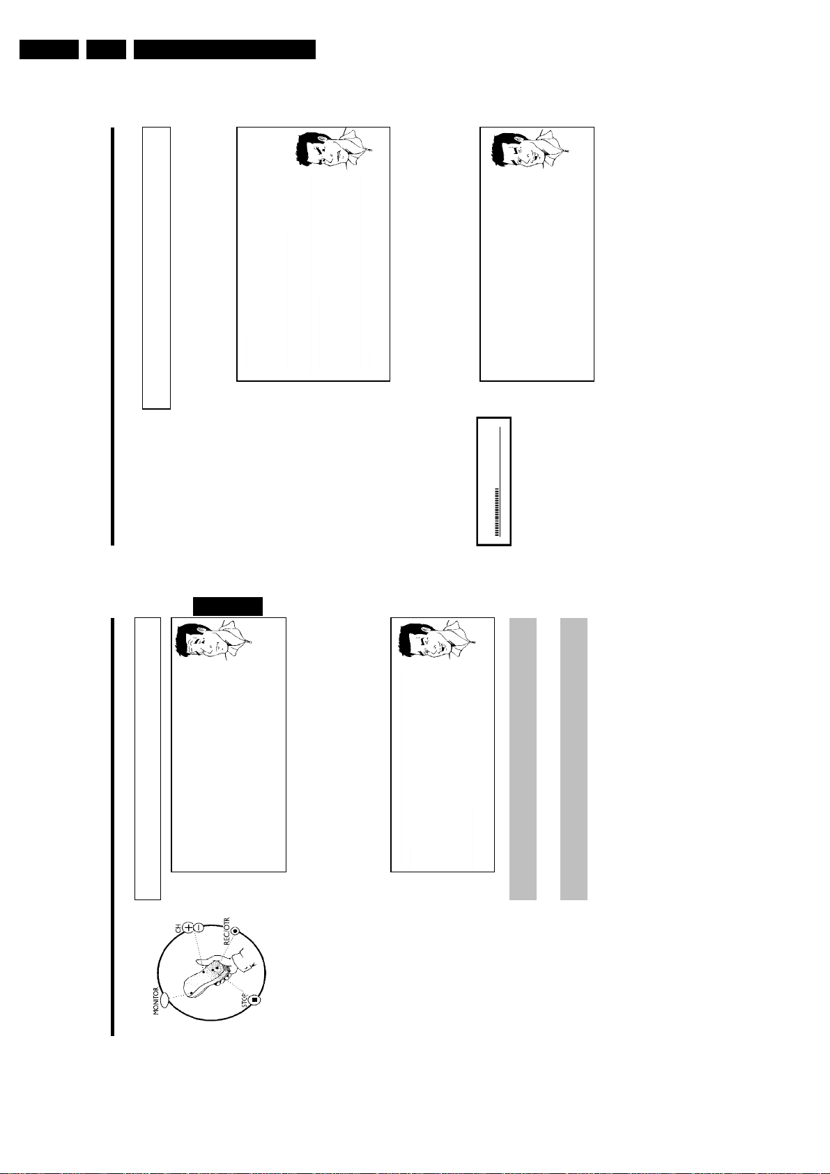
EN 28 DVDR80/0x13.
Directions For Use
recorder.
Recording without automatic switchoff
1 Switch on the TV set and select the programme number for the DVD
2 Insert a disc on which the recording is to be made. This disc is then
checked for content and system. READING' will appear on the display.
aIndex display
b A DVD+RW disc has been inserted that already contains recordings. Use
Problem
Tip
Manual recording
S-VIDEO socket has priority.
Switching between the S-VIDEO and VIDEO sockets takes place
automatically. If both sockets are in use, the signal at the
to start.
the CH+ A or CH- B button to select the point where the recording is
The message 'EMPTYDISC' appears in the display
A dialog box appears asking you whether you want to delete the
contents or eject the disc
video-compatible (e.g. a data disc). Recordings on this disc can only be
made if the entire disc is first deleted with the REC/OTR n button.aThe message 'Title limit' appears on the screen if a recording is to
be made
a
a
b The disc inserted is a DVD+RW but its contents are not DVD
b The disc inserted is a blank DVD disc.
b A disc may contain a maximum of 48 titles (including blank titles). Delete
titles or change the disc.
switch to the internal tuner in the DVD recorder.
3 If necessary, use the MONITOR button on the remote control to
name) you want to record. This will appear on the display:
4 Use CH+ A or CH- B to select the programme number (station
Programme numbers of the external inputs:
'EXT1' Scart socket at the back EXT 1 TO TV-I/O
'EXT2' Scart socket at the back EXT 2 AUX-I/O
'CAM1' Front SVHS/audio sockets S-VIDEO / left AUDIO right
'CAM1' Front video/audio sockets A/V S-VIDEO / left AUDIO right
'CAM2' Digital Video (i Link) front socket DV IN
RECORD on the DVD recorder.
'SAFE REC' appears on the display.
For DVD+R discs each new recording is always added at the end of
all previous recordings as existing recordings cannot be overwritten.
recordings, hold down the REC/OTR n button until the message
This will, for example, appear in the display:
If you want to start the recording at the end of the existing
5 To start recording, press REC/OTR n on the remote control or
1 FREETITLE P01
46
Which discs can I use for recording?
General
Manual recording
With this DVD recorder, you can record on two types of DVD:
DVD+RW
This disc can be written to and then the contents deleted.
DVD+R
This type of disc can only be recorded once.
ENGLISH
If you want to play this DVD in a DVD player it must be finalized using the
'Finalise disc' function. It is not possible to make further recordings using
this disc.
?
If this disc is to be played in a DVD recorder it must not be finalised.
Recordings can be added and deleted. The disc space (playback time) from the
deleted recording cannot be recovered for further recordings
Use the 'Manual recording' function to spontaneously start recording (e.g. to record a TV show
already in progress).
In the 'index display' select the title to be overwritten or 'Empty title' with CH- B , CH+ A .
If you insert recordings between existing recordings, check the lengths of the old and new
recordings. If the new recording is too long the subsequent recording (title/chapter) will be
overwritten.
Insert new recordings at the end of all existing recordings (Safe
Record)
To add a new recording at the end of the last recording on the disc, hold
45
Tip
display.
For DVD+R discs each new recording is always added at the end of all
previous recordings as existing recordings cannot be overwritten.
down the REC/OTR n button until the message 'SAFE REC' appears on the
End of disc is reached
If the end of a disc is reached during recording, recording will stop and the
Recorder will turn itself off automatically.
Please refer to section 'Recording without automatic switchoff', if you want to manually
start and stop your own recording.
If you want to start a recording manually but have it stopped automatically, read the section
'Recording with automatic switchoff'. (e.g. not to record to the end of the disc)
Read the section 'Automatic recording from a satellite receiver', if you want a recording
to be controlled automatically by a satellite receiver.
Read the section 'Direct record' if you want to record a programme currently being shown.
H
Manual recording
Page 29
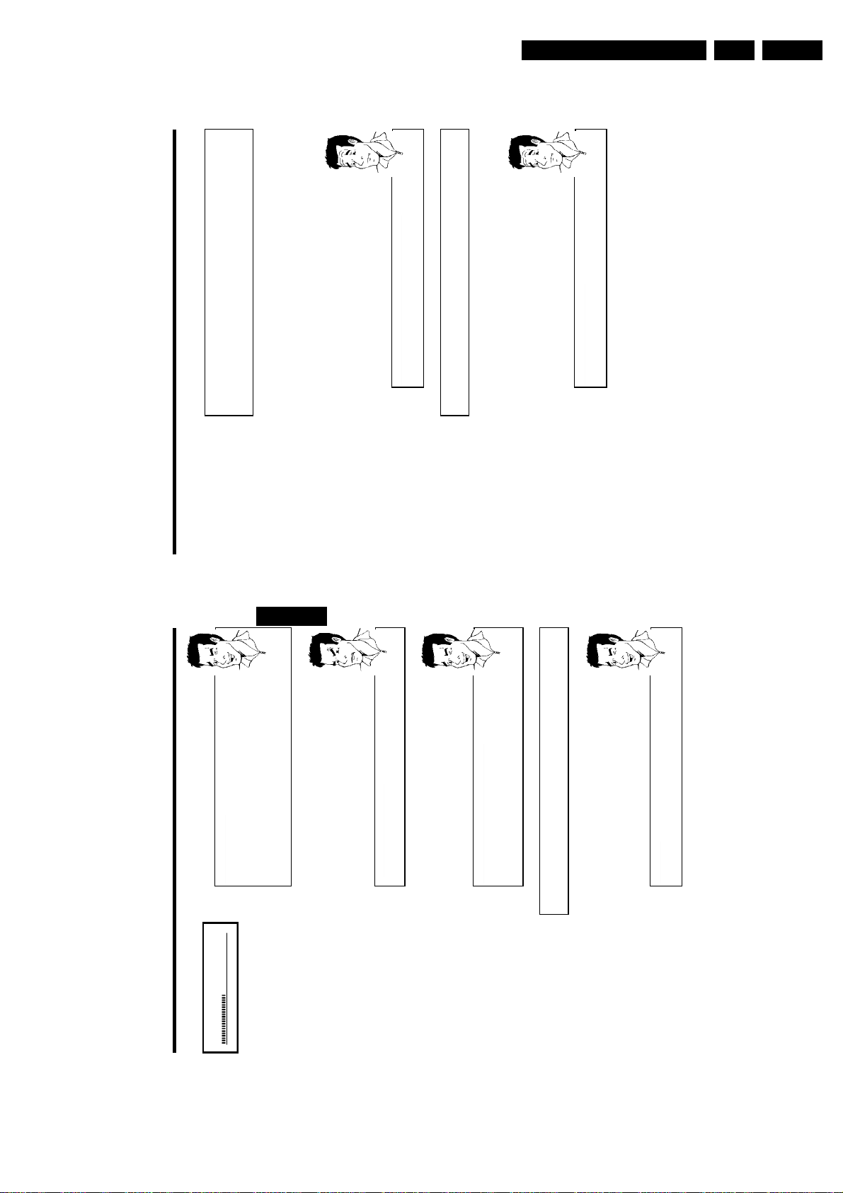
Directions For Use
EN 29DVDR80/0x1 3.
switch to the internal tuner in the DVD recorder.
name) you want to record.
Recording with automatic switchoff
(OTR onetouchrecording)
1 Insert a disc.
2 If necessary, use the MONITOR button on the remote control to
3 Use CH+ A or CH- B to select the programme number (channel
4 Press REC/OTR n on the remote control.
?
?
Manual recording
time.
How can I cancel the recording time I have just entered?
To delete an entry, press CLEAR while the display shows the recording
recording time.
5 Each time you press REC/OTR n you will add 30 minutes to the
Preventing accidental erasing of discs
To ensure you don't accidentally delete a recording you can protect the entire disc. You can
only ever protect the entire disc. You cannot protect individual recordings.
What happens with DVD+R discs?
As long as these discs are not finalised, they can be protected against
accidental erasure in the same way as DVD+RW discs.
1 Insert the disc to be protected.
2 While the index screen is displayed press STOP h on the remote
control. The first title is highlighted.
3 Press CH+ A . This takes you to the disc info screen.
Select the 'Protection' line.
4 Press the C button.
Confirm with C .
5 Select 'Protected' with the CH- B button and confirm with OK .
6 Press D and then DISC-MENU to terminate.
48
Insert chapter markers
During recording you can mark scenes so you can find them or hide them
later.
appears on the TV screen. In the display, the number of the 'CHAPTER'
During recording, press FSS & at the start point. 'Inserting marker'
increases by one.
Tip
For further information on titles and chapters, see the section on 'Changing to
another title/chapter' in 'Playback'.
ENGLISH
machine to stop the recording. 'MENU UPDT' will appear on the display.
The DVD recorder is writing the list of contents. Wait until the
6 Use the STOP h button on the remote control or h on the
message disappears from the display. The recording is then complete.
aThe display will read 'DISC ERR'
b Recording could not be completed correctly because of a disc error. Check
Problem
the disc and clean it if necessary.
Making recordings on DVD+R discs compatible
If you want to play back the recording on a DVD player, you need to finalise
the disc in the DVD recorder. You can prepare your DVD for use in a DVD
Tip
player using the 'Finalising' feature. See 'Finalising DVD+R discs' in 'Managing
the disc contents'.
the commercials.
Interrupt recording (Pause)
1 During recording press PAUSE 9 , for example to avoid recording
47
Tip
disappears from the display.
End recording
To end the recording, press the STOP h button. Wait until 'MENU UPDT'
2 To continue recording, press REC/OTR n .
C01 1:16:51 P01
Manual recording
Page 30
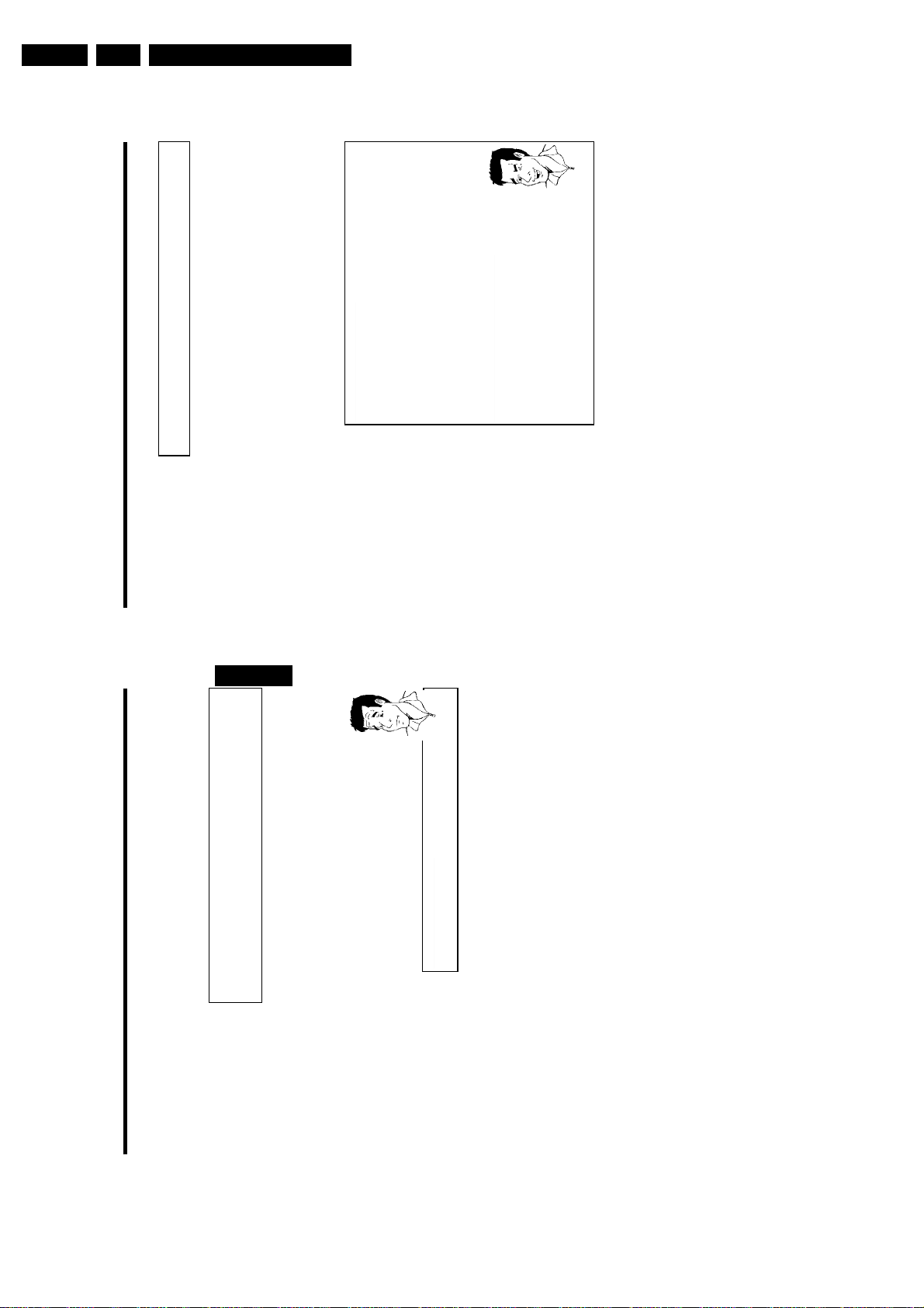
EN 30 DVDR80/0x13.
the DVD recorder.
Select the record mode with the button REC MODE on the remote
Directions For Use
Which recording types can I choose?
'M1': High Quality offers the best picture quality and a recording time of 1
hour.
'M2': Standard Play (pre-recorded DVD quality) offers standard picture quality
control.
and a recording time of 2 hours.
'M2x': Standard Play plus (better than S-VHS quality) offers standard picture
quality and a recording time of 2.5 hours.
'M3': Long Play (S-VHS picture quality). Recording time of 3 hours.
Tip
Manual recording
' symbol with D or C .
A
C .
select the settings 'Stndrd' (Standard) or 'Sport' (for rapid movements)
In the line 'Record mode' select the recording type with D or C .5Confirm using OK and SYSTEM-MENU .6If you have selected the recording mode 'M3', 'M4'or'M6', you can
4
in the 'Filter mode' line.
Press the SYSTEM-MENU button.2Select '
Can I select the recording type via a menu as well?
Select 'Record settings' using CH- B or CH+ A and confirm with
1
3
'M4': Extended Play (better than VHS picture quality). Recording time of 4
hours.
'M6': Super Long Play (VHS picture quality). Recording time of 6 hours.
Selecting the recording type (Quality)
You can select the picture quality of the recording using the recording quality feature and hence
the maximum recording time per disc.
You can check the quality by changing the recording mode and then watching the picture from
the built-in tuner ( MONITOR button).
During playback, the correct picture quality will automatically be selected.
1 Switch on the TV set. If required, select the programme number for
50
ENGLISH
49
?
The entire disc is now protected.
If an attempt is made to record on a protected disc, 'DISC LOCK' will appear on the display and
'Disc locked' will appear on the screen.
Lining up recordings within a title
(assemble cut)
On a recorded DVD+RW disc you can add another recording to an existing title. This recording
is added to the title as a 'chapter'. The existing information will be overwritten starting from this
point. Titles will also be overwritten that follow the current title depending on the length of the
new recording. The recording type (Quality) will be taken from the current title.
What happens with DVD+R discs?
New recordings on 'DVD+R' discs can only be added after existing recordings.
It is not possible to overwrite existing recordings on 'DVD+R' discs.
To play back this recording, press SYSTEM-MENU and use the C button to select the 'C'
(Chapter) symbol. You can also use the T/C key.
For further information, see 'Changing to another title/chapter' in 'Playback'.
1 In the index display, find the title to which the new recording is to be
added.
2 Look at the last minute of the old recording (playback)
3 Press PAUSE 9 on the remote control at the position where the
new recording is to go. '9' will appear on the screen.
remote control.
The new recording will be inserted.
internal tuner.
4 To monitor the recording you can press MONITOR to switch to the
6 Stop recording with STOP h .
5 Now start recording as usual by pressing REC/OTR n on the
Manual recording
Page 31

How does Direct Record work?
Directions For Use
EN 31DVDR80/0x1 3.
?
Problem
Manual recording
TV set. Please do not change the TV channel on the TV set while 'WAIT'is
shown in the display.a'NOTV' appears in the display
Check that all TV channels saved on the TV set are available on the DVD
recorder. If required, save any missing channels. Please read 'Manual TV
channel search' in 'Installing your DVD recorder'.
The DVD recorder compares the TV channel selected on the TV set with its
stored TV channels via the scart cable. If the same TV channel is found, it
switches the DVD recorder to the corresponding programme number and
starts recording.
Please do not change channel on the TV during the search. This could affect
the tuning of the DVD recorder.
recording from.
aThe display will read 'WAIT'
b The DVD recorder is comparing its saved TV channels with those of the
b This TV channel could not be found in the DVD recorder's memory.
b Check the connectors at both ends of the scart cable.
b Check your TV's operating instructions to see which scart socket is used
for video signals.
b If the problem persists, you won't be able to use this feature.
Direct Record
Can you record the right TV channel in seconds when the DVD recorder is switched off? No
problem. If recording is started manually, the switchedoff DVD recorder takes the current TV
channel from the TV set via the scart cable.
You will find more information on how to switch 'Direct record' on or off in the next section
'Direct record'.
ENGLISH
1 On the TV set, select the programme number you want make the
2 Press REC/OTR n with the DVD recorder switched off.
3 Stop recording with STOP h .
52
51
Tip
Automatic recording from a satellite
receiver (Sat recording)
You can use this function if you own a satellite receiver that can control other devices via a
scart cable and a programming function (timer). For more information, please see the operating
instructions for the satellite receiver.
1 Switch on the TV set. If required, select the programme number for
the DVD recorder.
2 Press SYSTEM-MENU on the remote control. The menu bar
appears.
' symbol with D or C .
A
Switching off 'Sat Recording'
C .
5 Select 'Sat record' using CH- B or CH+ A .
4 Select 'Record settings' using CH- B or CH+ A and confirm with
3 Select '
6 Select 'EXT2' with D or C .
To switch off the function, select 'Off' using C or D .
DVD recorder to the corresponding scart socket on the satellite
receiver.
7 Confirm with OK .
8 Use a scart cable to connect scart socket EXT 2 AUX-I/O on the
9 To end, press SYSTEM-MENU .
0 Insert a disc you want to use for recording.
A Programme the satellite receiver with the required information
(programme number of the TV channel, start time, end time).
If necessary, please see the operating instructions for your satellite
receiver.
B Switch off the DVD recorder using STANDBY m .'SAT' also
appears in the display to indicate that the function is active.
The DVD recorder is now ready to record. The start and end of the recording is controlled via
scart cable EXT 2 AUX-I/O .
Manual recording
Page 32

EN 32 DVDR80/0x13.
General
When a recording is made to disc, the following additional information is also stored at the
beginning of the recording:
•) Name of the recording
If the TV station does not transmit a name, only the
channel number and time will be stored as the name
•) Length of the recording
•) Record type (Quality)
•) Date of the recording
•) Index picture of the recording
A marker will be set every 5-6 minutes if the 'Auto chapters' function is activated in the
Directions For Use
'Record settings' menu. This marker is known as a 'chapter'.
These markers can be changed when the recording has finished.
Can markers be set on a DVD+R disc?
?
Markers can be set on these discs if they have not been finalised.
It is also possible to add 'chapters' later. This means that scenes you do not want to see during
playback, such as commercials, can be hidden or skipped. During playback you can watch your
recording as a continuous sequence without the hidden chapters.
Select from the following chapters:
'Favorite Scene Selection',
to divide the title into chapters or to manage the chapters.
'Editing recording titles (name)',
to change the recording names.
'Play complete title',
to play the entire title including the hidden chapters.
'Delete recording/title'to delete the relevant title and therefore also the recording.
Managing the disc contents
'Disc settings'to change the general settings of the disc.
Charly 1
00:29:59 • M1
Fri15/02/2003
Managing the disc contents
I
Empty title
01:30:01
the DVD recorder.
appears.
ENGLISH
' symbol with D or C .
A
54
53
C .
D or C .
Switching 'Direct Record' on or off
5 Select 'Direct Record' using CH- B or CH+ A .
6 Select 'On' (Direct Record on) or 'Off' (Direct Record off) using
7 Confirm with OK .
8 To end, press SYSTEM-MENU .
1 Switch on the TV set. If required, select the programme number for
2 Press SYSTEM-MENU on the remote control. The menu bar
4 Select 'Record settings' using CH- B or CH+ A and confirm with
3 Select '
9 Switch off with STANDBY m .
Manual recording
Page 33

Directions For Use
EN 33DVDR80/0x1 3.
3 Using C select 'hidden'. The picture is shown darker.
Switching quickly
You can switch between show chapters ('visible') and hide chapters
Tip
('hidden') quickly and easily using SELECT .
Tip
with C .
3
Press the T/C button on the remote control. Titles and chapters are
displayed at the top of the screen.2Select title (T) or chapter (C) with C or D .3Use CH+ A or CH- B to select the title/chapter channel you want to
screen.
Favorite Scene Selection
How can I select different chapters?
Insert marker Press OK
Current chapter visible
Delete marker
Delete all markers
control. The 'Favorite Scene Selection' menu appears on the TV
4 To end, press FSS & .
During playback this chapter will be skipped.
If the chapter is not visible, select 'visible' in step
Deleting chapter markers
Within a title you can delete either all markers or individual markers.
1 While the relevant chapter is playing, press FSS & on the remote
1
New index picture
edit.
'Delete all markers' for all chapters within the selected title.
3 Confirm with OK .
2 Use CH- B to select either 'Delete marker' for this chapter or
Press FSS to exit
Divide title
4 To end, press FSS & .
Managing the disc contents
56
Favorite Scene Selection
In this menu you can adapt a title to suit your particular needs.
You can insert/delete chapter markers, hide chapters, select a new index, or split up a title.
Press FSS & on the remote control during recording to open this menu.
ENGLISH
Insert chapter markers
During recording, you can set or delete chapter markers within a title.
The maximum number of chapters per disc is 124 and 99 per title. If one of these limits is
reached the following message will appear on the screen: 'Chapter limit'. You need to delete
some markers before you can insert new ones or make recordings.
55
Tip
'X' will appear on the screen:
This DVD is write-protected or the disc is a finalised DVD-R. Subsequent
the TV screen.
appears on the TV screen.
2 Confirm 'Insert marker' by pressing OK .'Inserting marker'
Favorite Scene Selection
appropriate point. The 'Favorite Scene Selection' menu appears on
1 During playback, press FSS & on the remote control at the
changes cannot be made.
3 To stop this function, press FSS & .
Press FSS to exit
Hiding chapters
Initially, all the chapters are visible. You can hide chapters for playback (e.g. advertisements) or
make them visible again. In editing mode, hidden chapters are shown as dimmed.
control. The 'Favorite Scene Selection' menu appears on the TV
1 While the relevant chapter is playing, press FSS & on the remote
screen.
Favorite Scene Selection
How can I select different chapters?
Press the T/C button on the remote control. Titles and chapters are
1
displayed at the top of the screen.2Select title (T) or chapter (C) with C or D .3Use CH+ A or CH- B to select the title/chapter channel you want to
Press FSS to exit
Tip
edit.
2 Select 'Current chapter' using CH- B .
Insert marker Press OK
Current chapter visible
Delete marker
Delete all markers
New index picture
Divide title
Insert marker Press OK
Current chapter visible
Delete marker
Delete all markers
New index picture
Divide title
Managing the disc contents
Page 34

EN 34 DVDR80/0x13.
edit and confirm with C . The menu for editing names appears.
Directions For Use
until you have made the changes you want.
5
and
4
be changed/re-entered.
upper and lowercase using SELECT . You can delete the character
using CLEAR .
screen for confirmation.
confirm with C . The title editing menu will appear.
Managing the disc contents
OK .
including the hidden chapters.
Editing recording titles (name)
Some TV stations transmit the title (name) of a programme. In this case, the name will be
included automatically (e.g. 'ROCKY'). Otherwise, the only the programme number (programme
name) and the time are stored as the name of the recording. The name of the recording can
only be changed after the recording has been completed.
2 Using CH+ A or CH- B select the title whose name you want to
1 Press the STOP h button or during playback press DISC-MENU .
ENGLISH
3 Select 'Name' using CH+ A or CH- B and confirm with C .
4 Using C or D select the position where the letter/number/icon is to
5 Change the icon using CH+ A or CH- B . You can switch between
6 Repeat
7 Save the new name with OK .'Storing name' appears on the TV
8 To end, press D .
Settings for title Charly 1
Name Charly1
Play full title
Erase this title
Playing the entire title
If you have hidden certain sections (chapters) of a title, this setting lets you watch the entire title
including the hidden sections. To do this, proceed as follows:
3 Select 'Play full title' using CH+ A or CH- B and confirm with
2 Using CH+ A or CH- B select the title you want to play all of and
1 Press the STOP h button or during playback press DISC-MENU .
Settings for title Charly 1
4 Playback starts automatically. The title is played in its entirety -
Name Charly1
Play full title Press OK
Erase this title
58
57
?
Changing the index picture
Normally the first picture of a recording is used as the index picture. You can however choose
any picture from the recording as the index picture.
1 During playback, search for location of the new index picture. Press
the PAUSE 9 button.
2 Press the FSS & button. The 'Favorite Scene Selection' menu
appears on the TV screen.
Favorite Scene Selection
Can I split titles on DVD+R discs?
As recordings on DVD+R discs cannot be overwritten, it is not possible to
split titles.
control. The 'Favorite Scene Selection' menu appears on the TV
screen.
4 Start the change with OK .'Updating menu' appears on the TV
3 Select line 'New index picture' and confirm with OK .
Insert marker Press OK
Current chapter visible
Delete marker
Delete all markers
New index picture
Once the revision has been completed successfully the DVD recorder reverts to the index
Press FSS to exit
Divide title
overview.
Splitting titles
You can split a title into several sections (titles) of any size. Each of these sections (titles) is
identified by its own index.
Note: This split cannot be undone.
screen.
1 While the relevant title is playing, press FSS & on the remote
Favorite Scene Selection
2 Select 'Divide title' and confirm with the OK button.
Insert marker Press OK
Current chapter visible
Delete marker
3 If you are sure, press OK to start the process. 'Dividing title'
Delete all markers
appears on the TV screen.
New index picture
Divide title
4 Wait until the new title is displayed with an index picture in the index
Press FSS to exit
picture overview.
The process of splitting the title is now complete.
Managing the disc contents
Page 35

1 In the 'Disc info display' press C . The 'Settings for' menu appears
Changing the disc name
on the TV screen.
be changed/re-entered.
3 Using C or D select the position where the letter/number/icon is to
2 Select 'Disc name' using CH+ A or CH- B and confirm with C .
upper and lowercase using SELECT . You can delete the character
4 Change the icon using CH+ A or CH- B . You can switch between
Directions For Use
until you have made the changes you want.
4
and
3
using CLEAR .
5 Repeat
screen for confirmation.
6 Save the new title with OK .'Storing name' appears on the TV
7 To end, press D .
Finishing editing
If one or more titles have been edited a DVD player may still display the original titles. You can
prepare your disc in such a way that a DVD player will be able to play the edited version.
on the TV screen.
1 In the 'Disc info display' press C . The 'Settings for' menu appears
2 Select 'Make edits compatible' using CH+ A or CH- B and
EN 35DVDR80/0x1 3.
Problem
Managing the disc contents
To end, press SYSTEM-MENU .
a'Make edits compatible' does not appear
b Your disc is already compatible. There is no need for conversion.
confirm with OK .
will last.
3 The screen displays 'This will take' to show how long the process
will move from left to right indicating progress.
4 To confirm press OK .'Working' appears on the TV screen. A bar
Settings for Philips1
Disc name Philips1
Protection Unprotected
Erase disc
ENGLISH
confirm with C . The title editing menu will appear.
Deleting recordings/titles
You can delete specific recordings from a disc. To do this, proceed as follows:
1 Press the STOP h button or during playback press DISC-MENU .
2 Using CH+ A or CH- B select the title you want to delete and
3 Select 'Erase this title' using CH+ A or CH- B and confirm with
60
59
?
Can titles be deleted from a DVD+R disc?
Titles on DVD+R discs are only marked as deleted. 'Deleted title' will appear
in the display instead of 'Empty title'. During playback the 'deleted' title is
skipped. The space used for this title cannot be used again as the title has not
been physically deleted. Once the disc has been finalised no further changes
OK .'This will completely erase this title' appears on the TV
D .
screen.. 'Press OK to confirm'.
4 If you want to delete this title, press OK to confirm. Otherwise press
5 'Erasing title' appears on the TV screen.
new recording can now be made here.
If the deleted title was very short (less than 1 minute) 'Empty title'
will not appear at this point.
6 At this point 'Empty title' appears in the 'index picture display'. A
can be made.
Disc settings
This screen appears beforethe first title and contains general information about the current disc.
You can:
•) change the name of the disc
•) activate or deactivate write protection on the disc
•) Finish editing (make the disc DVD compatible)
•) finalise a DVD+R
•) delete a DVD+RW
To get to this display, proceed as follows:
1 Press the STOP h button or during playback press DISC-MENU .
2 Select the first title with CH+ A or press STOP h .
3 Press the CH+ A button. The disc info display will appear.
Philips1
00:35:59 used
Fri15/02/2003
PAL
Settings for title Charly 1
Name Charly1
Play full title
Erase this title Press OK
DVD playback
Managing the disc contents
Page 36

EN 36 DVDR80/0x13.
General
Use 'Programming a recording (TIMER)', to automatically start and stop a recording at a later
date.
Directions For Use
?
Programming a recording (TIMER)
If you want to programme a time that is different from the VPS or PDC time,
you must switch off VPS or PDC.
time. If you want to record two or more TV programmes on a TV channel
using 'VPS/PDC', you will need to programme t hese as two separate
recordings.
speed and positioning the laser) before recording can start, it is possible that
the recorder will miss the first few seconds of a TV show recorded with
VPS/PDC.
'VPS/PDC time' is indicated, e.g.: '20.15 (VPS/PDC 20.14)', the VPS/PDC time
'20.14' must be entered exactly to the minute during programming.
What is 'VPS/PDC'?
'VPS' (Video Programming System)/'PDC' (Programme Delivery Control) are
used to control the start and duration of TV channel recordings. If a TV
programme starts earlier or ends later than was scheduled, the DVD recorder
will then turn on and off at the correct time.
What do I need to know about 'VPS/PDC'?
• Usually the start time is the same as the VPS or PDC time. If a different
The DVD recorder will switch to the right programme number and begin recording at the
correct time.
With this DVD recorder, you can pre-programme up to six recordings within a period of one
month.
To make a programmed recording, your DVD recorder needs to know:
* the date you want to make the recording
* the programme number of the TV channel
* the start and stop time of the recording
* VPS or PDC on or off
* the recording mode ('M1/M2/M2x/M3/M4/M6')
This information is saved in a 'TIMER block'.
• Only one TV program of a TV channel can be controlled using 'VPS/PDC' at a
In this case, disable VPS/PDC and enter a start time one minute earlier.
• Since the DVD recorder requires a certain lead time (for getting the disc up to
Programming a recording (TIMER)
J
Finalising DVD+R discs
This feature is required to play back a DVD+R disc in a DVD player. Once the disc has been
finalised no further recordings or changes can be made.
on the TV screen.
1 In the 'Disc info display' press C . The 'Settings for' menu appears
ENGLISH
OK .
2 Select 'Finalise disc' using CH+ A or CH- B and confirm with
a'Finalise disc' does not appear
b Either there is no DVD+R disc inserted or the disc is already finalised.
To end, press SYSTEM-MENU .aThe 'Settings for' menu does not appear
b The menu may not appear if the disc has been recorded on another DVD
Problem
' menu,
A
recorder. In this case, use the 'Finalise disc' feature in the '
under 'Features'.
will take.
3 The screen displays 'This will take...' to show how long the process
will move from left to right indicating progress.
4 To confirm press OK .'Working' appears on the TV screen. A bar
Delete DVD+RW disks
on the TV screen.
1 In the 'Disc info display' press C . The 'Settings for' menu appears
62
61
4 'Erasing disc' appears on the TV screen.
disc.
5 After deletion, the index picture display shows the free space on the
confirm'.
press D .
'This will erase all titles' appears on the TV screen. Press OK to
2 Select 'Erase disc' using CH+ A or CH- B and confirm with OK .
3 If you want to delete all the titles, press OK to confirm. Otherwise
Settings for Philips1
Disc name Philips1
Protection Unprotected
Erase disc PressOK
Managing the disc contents
Page 37

change the data. Select the appropriate input field with C or D .If
required, make changes using CH+ A , CH- B or the number
buttons 0..9 .
'Switching on 'VPS/PDC' in the 'Start' input field
('*' lights up). If you press SELECT again, you will switch 'VPS/PDC' off ('*'
goes out).
Select the 'Start' input field using C . Using SELECT switch on 'VPS/PDC'
Directions For Use
EN 37DVDR80/0x1 3.
Tip
Programming a recording (TIMER)
Changing the recording mode in input field 'End'
Select the 'End' input field using C .
Use SELECT to select the recording mode 'M1, M2, M2x, M3, M4, M6'.
information is stored in a TIMER block.
The disk you have inserted will be checked.
The programmed recording will only function properly if the DVD
recorder has been switched off using the STANDBY m button.
6 The decoded data appears after confirmation. You can go back and
Timer
Rec
VPS
ShowView system
Mode
M2
21:30
PDC End
Start
20:15
Prog.
BBC1
Date
01
System
®
To store
Press OK
Mo-Fr/Weekly
Press SELECT
ENGLISH
number is found in
®
programming number. This 9-digit ShowView
®
7 If all information is correct, press the OK button. The programming
8 To end, press TIMER .
9 Insert a recordable disc (one without write protection).
0 Switch the DVD recorder off with STANDBY m .
If any of the TIMER blocks are in use, 'TIMER' will light up on the recorder display.
64
63
Tip
Problem
Programming recordings with the
ShowView
Thanks to this programming system, you no longer need to tediously enter the date, programme
number, start and end times. All the information needed by the DVD recorder for programming
is contained in the ShowView
most TV listings magazine.
1 Switch on the TV set. If required, select the programme number for
the DVD recorder.
2 Press TIMER on the remote control.
The programming method selected last is marked.
with C .
3 Select 'ShowView system' using CH- B or CH+ A and confirm
and can be found next to the start time of the TV programme in your
4 Enter the entire ShowView number. This number is up to 9 digits long
TV listings magazine.
e.g.: 5-312-4 or 5,312 4
Enter 53124 for the ShowView-number.
If you make a mistake, you can clear your instructions with CLEAR .
Timer
ShowView system
Selecting daily/weekly recordings
Using SELECT , select from the following options:
'Mo-Fr': Repeated daily recordings (Monday to Friday).
---------
ShowView number
'Weekly': Repeated weekly recordings (every week on the same day).
5 Confirm with OK .
To store
Press OK
Mo-Fr/Weekly
Press SELECT
aThe following message appears on the screen: ' Please enter
programme number'
the ShowView number. Use C , D or the number buttons 0..9 on the
remote control to select the appropriate programme number (name) of the
TV channel and confirm with OK .aThe following message appears on the screen: 'ShowView number
b The programme number of the TV channel has not yet been assigned to
recorder').
wrong'
using the SYSTEM-MENU button.
The following message appears on the screen: 'Weekend
programming not possible'
only be used for recordings to be made from Monday to Friday.
a
b Check the time/date (see 'Setting the time & date' in 'Installing your DVD
b The entered ShowView number is incorrect. Correct your entry or cancel
b A daily recording was entered for the wrong day. Daily programming can
Programming a recording (TIMER)
Page 38

EN 38 DVDR80/0x13.
the DVD recorder.
The programming mode selected last is marked.
How to change or delete a programmed
recording (TIMER)
1 Switch on the TV set. If required, select the programme number for
2 Press TIMER on the remote control.
Directions For Use
Tip
Programming a recording (TIMER)
screen.
'-- ---' appears rather than the displayed values
Press the CLEAR button.2Confirm with OK .'Timer Cleared' will briefly appear on the TV
Delete programmed recording
or delete with CH- B or CH+ A .
3 Select 'Timer List' using CH- B or CH+ A and confirm with C .
4 Select the programmed recording (TIMER) you want to check, change
Rec
ModeM2--
End
21:30
--:--
VPS
PDC
*
Start
20:15
--:--
Prog.
BBC1
-----
Date01--
Timer List
Timer
To end, press TIMER .
1
Total record time: 01:15
3
To exit
Press TIMER
To change
Press ›
number buttons 0..9 .
Select the input field with D or C .
If required, change the information with CH+ A , CH- B or the
6 Confirm with OK .
5 Press C .
7 To end, press TIMER .
'NexTView Link'
8 Switch off with STANDBY m .
This DVD recorder is equipped with the 'NexTView Link' feature. If your television is also
equipped with this function, you can mark TV programmes on the television for programming.
These TV programmes will automatically be transmitted to a TIMER block on the DVD
recorder. If you clear the marking of the TV programme on the television, the corresponding
TIMER block on the DVD recorder will also be cleared.
For more information, read the instruction manual of your TV set.
66
System
®
Programming recordings without the
ShowView
the DVD recorder.
1 Switch on the TV set. If required, select the programme number for
ENGLISH
The programming method selected last is marked.
2 Press TIMER on the remote control.
confirm with the C button.
3 Select line 'Timer programming' with CH- B or CH+ A . and
Rec
VPS
Timer programming
Timer
The information will appear on the screen.
Mode
M1
21:30
PDC End
Start
20:15
Prog.
BBC1
Date
01
65
Tip
EXT 1 TO TV-I/O ('EXT1') or EXT 2 AUX-I/O ('EXT2').
'Mon': Repeated weekly recordings (every week on the same day, e.g.
Monday).
Programme numbers of the 'EXT1' and 'EXT2'scart socket
You can also programme recordings from external sources via scart socket
'Switching on 'VPS/PDC' in the 'Start' input field
Select the 'Start' input field using TIMER . Using SELECT switch on
'VPS/PDC' ('*' lights up). If you press SELECT again, you will switch
'VPS/PDC' off ('*' goes out).
Changing the recording quality in input field 'End'
Select the 'End' input field using C .
Use SELECT to select the recording mode.
information is stored in a TIMER block.
6 If all information is correct, press the OK button. The programming
7 To end, press TIMER .
The disk you have inserted will be checked.
8 Insert a DVD (one without write protection).
The programmed recording will only function properly if the DVD
recorder has been switched off using the STANDBY m button.
9 Switch off with STANDBY m .
If any of the TIMER blocks are in use, 'TIMER' will light up on the recorder display.
Programming a recording (TIMER)
Selecting daily/weekly recordings
In 'Date' use SELECT to select from the following options:
'Mo-Fr': Repeated daily recordings from Monday to Friday
buttons 0..9 .
5 Enter information with CH- B or CH+ A or with the number
4 Select the input field with D or C .
To store
Press OK
Mo-Fr/Weekly
Press SELECT
Page 39

Picture settingSound settingLanguage settingAdditional settingsRemote control settingsDisc settingsRecording settingsInstallation
Directions For Use
' using D or C and confirm with CH- B .
A
with C .
the DVD recorder.
appears.
with C .
EN 39DVDR80/0x1 3.
User preferences
setting with D or C .
In this section you will learn how to set your user preferences on the DVD recorder. The
symbols have the following meanings:
User preferences
K
ENGLISH
8 To close the menu item, press D .
Picture settings
You can choose the following features in this menu:
'TV shape'
The picture signal from your DVD Recorder can be set to match your TV screen.
'4:3 letterbox': for a 'wide-screen' picture with black bars at the top and bottom
'4:3 panscan': for a full-height picture with the sides trimmed.
'16:9' : for a wide-screen TV set (screen edge ratio 16:9)
'Black level shift'
Adapts the colour dynamics for NTSC playback
Picture
TV shape 16:9
Black level shift Off
Vertical video shift ï
SCART video RGB
5 Select the appropriate line using CH- B or CH+ A and confirm
6 Select the appropriate function using CH- B or CH+ A or the
1 Switch on the TV set. If required, select the programme number for
2 Press SYSTEM-MENU on the remote control. The menu bar
4 Select the appropriate function with CH- B or CH+ A and confirm
3 Select '
7 Confirm the new setting by pressing OK .
68
67
Problem solving for programmed
recordings
While a programmed recording is being made, you cannot operate your DVD recorder manually.
If you want to cancel the programmed recording, press STANDBY m .
b
PROBLEM SOLUTION
The DVD recorder is
The DVD recorder was switched on several minutes before the start of a programmed recording.
Switch off the DVD recorder using STANDBY m . A programmed recording (timer) will only
function if the DVD recorder is switched off ( STANDBY m button).
b
not responding
'Switch off, timer
recording' flashes on
the TV screen.
Either a disc has not been inserted or the disc cannot be used for recording. Insert a disc on
which recordings can be made. Switch off the DVD recorder using STANDBY m .
b
Error message: 'Insert
recordable disc'
A write-protected disc has been inserted. Undo the write protection (see 'Preventing accidental
erasing of discs' in 'Manual recording') or insert a different disc.
b
The error message
'Disc locked' appears
briefly on the screen.
or check a programmed recording (TIMER block), select it with CH+ A or CH- B .
If this error message appears after pressing TIMER , then all TIMER blocks are already
programmed. No more recordings can be programmed. Press the C button. If you want to clear
b
Error message:
'Memory full'
The 'Data error'
The data for the recording could not be transferred. Please check date, start time and end time
of the programmed recording.
b
message appears on
Two programmed recordings overlap.bIf you ignore this error message the show with the earlier start time will be recorded first. The
b
the screen.
start of the second show will not be recorded.bChange the setting for either of the two recordings.bClear either of the two recordings
The 'Collision'
message appears on
the screen.
Programming a recording (TIMER)
Page 40

EN 40 DVDR80/0x13.
Language settings
You can choose the following settings in this menu:
Directions For Use
User preferences
again.
'Audio Language'
Playback audio language
'Recording audio'
Audio recording
'Subtitle'
Subtitle language
'Menu'
Screen menu language
'Country'
'Country'
Additional settings
You can select the following functions in this menu:
'Status box'
Along with the on screen menu, the OSD (On Screen Display) also displays information on the
current operating status (counter, playback, recording, TV channel, etc.) on the TV screen.
You can switch off the information about the operating status so that the on screen display
(OSD) is not recorded during copying.
'On': The OSD information appears in every selected mode for a few seconds and disappears
'Off': The OSD information is switched off. It is no longer displayed on the screen.
Language
Audio Language English
Recording audio Language 1
Subtitle English
ENGLISH
Menu English
Features
Status box On
Standby Off
Country Other
Display Bright
70
69
Modulation).
For receivers/amplifiers without digital multichannel sound decoders.
signals are converted to PCM (Pulse Code Modulation).
For receivers/amplifiers with digital multichannel sound decoders.
'Vertical video shift'
Use this feature to adjust the position of the picture on your TV left or right using D , C to
suit your TV set.
'SCART video'
By default the recorder is set to 'RGB'. Select 'S-Video' if you want to connect an S-VHS
recorder.
Sound settings
Depending on which audio outputs are used, you can select the settings in this menu.
If you only use the analogue audio output ( OUT L AUDIO R ), select the settings 'Off' in the
'Digital output' menu.
'Digital output'
For devices connected to the DIGITAL AUDIO OUT socket, you can select from the following
settings.
Sound
Digital output All
'All': Dolby Digital and DTS signals are fed unaltered to the digital output. MPEG-2 multi-channel
Analogue output Stereo
Night mode Off
'PCM only: Dolby Digital and MPEG-2 multi-channel signals are converted to PCM (Pulse Code
For devices with analogue audio input.
'Off: Digital output switched off.
'Analogue output'
For devices connected to the analogue audio output ( OUT L AUDIO R ), you can select from
the following settings.
'Stereo': For devices without DolbySurround or TruSurround. Use this setting if the DVD
surround-compatible two-channel output signal. For devices with Dolby Surround
Pro Logic decoder .
recorder is only connected to a stereo TV set.
'Night mode'
Night mode optimises the sound for playback at low volume. You are therefore less likely to
'Surround: Dolby Digital and MPEG-2 multi-channel are mixed down to a DOLBY
disturb your neighbours. This only works for Dolby Digital audio on DVD video discs.
User preferences
Page 41

Directions For Use
EN 41DVDR80/0x1 3.
User preferences
Disk feature menu
In this menu you can make the changes that relate to the disc:
'Access control'
Please read the next chapter on 'Access control (child lock)'.
Features
Status box On
ENGLISH
OPEN/CLOSE J ) when the disc is reloaded (disc is started) playback starts at the precise
'Auto resume'
If playback of a pre-recorded DVD video disc or video CD is interrupted (button STOP h or
location where it stopped. This applies not only to the current disc but to the last 20 discs
played.
This feature can be switched off if not required.
'PBC'
This line appears only if a VCD is loaded.
This function lets you activate or deactivate the PBC menu (Playback Control) for video CDs.
See 'Playing a (Super) Video CD'.
'Finalise disc'
This feature allows you to finalise DVD+R discs. If the disc has already been finalised this line will
appear darker.
'Adapt disc format'
If a DVD+RW has been recorded in a computer drive or in another DVD recorder the index
screen may not be displayed correctly.
This feature allows you to change the format of the disc.
It is therefore only visible if the disc format is different.
Standby Off
Display Bright
72
71
'Standby'
To save power, you can switch off the clock display on the DVD recorder. Programmed
(TIMER) recordings will still take place.
In addition, you can present the most important features of the DVD recorder in scrolling text
in the display (demo).
'Off': If the DVD-Recorder is switched off (button STANDBY m ), the clock display is visible.
'Demo mode': If the DVD recorder is switched off with the STANDBY m button, a list of the
most important features is shown in the display.
'Display'
You can change the brightness of the display on the DVD recorder. This setting only affects the
DVD recorder when it is switched on.
'Bright': The display appear with normal brightness. The disc tray light is switched on.
'Dimmed': The display appears less bright. The disc tray light is switched off.
'Off': The display and the disc tray light are switched off.
Remote Control settings
also switched off.
'Low power': If the DVD-Recorder is switched off (button STANDBY m ), the clock display is
In this menu you can set the remote control type to which your DVD recorder should respond.
The DVD recorder also responds to the remote control of a DVD player (remote
'DVD player': The DVD recorder responds to a DVD player remote control.
control code RC-6). Choose this setting if your Philips TV remote supports DVD
functions.
'DVD recorder': The DVD recorder only responds to the supplied remote control.
User preferences
Page 42

EN 42 DVDR80/0x13.
Directions For Use
Authorising a disc
1 Insert a disc. The access control box will appear after a short delay.
' icon is visible. The icon
Access control (Child Lock)
'. The disc is now locked.
changes to '
start automatically, press PLAY G .
3 Enter your PIN code using the number buttons 0..9 .
2 Using CH+ A or CH- B select 'Play once'or'Play always'.
Double-sided DVDs may have a different ID for each side. For these discs, each side must be
authorised. Multi-volume video CDs may have a different ID for each volume. For these CDs,
each volume must be authorised.
Locking unlocked discs
To lock a disc that was formerly authorised follow the instructions below
1 Insert a disc. Playback starts automatically. If the playback does not
2 Press the STOP h button while the '
Parental level control (DVD video only)
Films on pre-recorded DVD discs may contain scenes not suitable for children. Therefore, some
discs may contain 'Parental Control' rating information that applies to the entire disc or to
certain scenes on the disc.
The appropriate scenes have filter values that reach from 1-8. If such a scene is detected during
playback, the filter value set on the DVD recorder is compared to the scene. If the filter value is
higher than the setting, an alternative scene will be played (if available).
Most DVDs apply the rating to an entire DVD. Therefore, if certain scenes exceed the rating
you select, the entire disc will be blocked from viewing.
74
ENGLISH
73
Access control (Child Lock)
L
Child lock (DVD and VCD)
This feature enables discs to be locked for children.
When Child Lock is on, a 4-digit code (PIN) needs to be entered before a disc can be played.
You can also decide whether the inserted disc should always be played or should be played only
once, despite the child lock
.
9
' icon in
' icon using D or C .
A
(Disc features)' using CH- B or CH+ A and confirm
the DVD recorder.
•)'Play always':
This disc is stored in a memory with space for 50 child-safe discs. If more than 50 discs are
stored, the last disc in the list is removed and the new disc is added. The screen shows 'Child
safe' at the start of playback.
•)'Play once':
This disc is only authorised for single playback. If the recorder is switched off, the PIN code
must be re-entered.
Activating/deactivating child lock
1 Switch on the TV set. If required, select the programme number for
3 Press SYSTEM-MENU . The menu bar appears
2 Switch on the DVD recorder using STANDBY/ON m .
with C .
5 Select '
4 Select the '
7 Enter a 4-digit code of your choice. If the code is new, you may have
6 Confirm 'Access control' using C .
to enter the code a second time as confirmation.
8 Select 'Child lock' using CH+ A or CH- B and confirm with C .
' icon using CH- B or CH+ A .
9 Select the '
0 Confirm with OK .
A Quit the feature using D and SYSTEM-MENU .
Unauthorised discs can only be played by entering the four-digit PIN code.
To deactivate the child lock, select the '
Access control (Child Lock)
Page 43

Changing the country
The set filter values depend on the respective country. It is therefore necessary to enter the
country to which these filter values apply.
the DVD recorder.
1 Switch on the TV set. If required, select the programme number for
Directions For Use
EN 43DVDR80/0x1 3.
Access control (Child Lock)
(Disc features)' using CH- B or CH+ A and
' icon using D or C .
A
C .
6 Confirm the line 'Access control' using C .
the code a second time as confirmation.
7 Enter your four-digit code. If the code is new, you may have to enter
Disc features
confirm with C .
5 Select line '
3 Press SYSTEM-MENU . The menu bar appears
4 Select the '
2 Switch on the DVD recorder using STANDBY/ON m .
8 Select 'Change country' using CH- B or CH+ A and confirm with
9 Select the corresponding country using CH+ A or CH- B and
confirm with OK .
0 To end, press D and then SYSTEM-MENU .
Activating/deactivating parental level
control
1 Switch on the TV set. If required, select the programme number for
the DVD recorder.
2 Switch on the DVD recorder using STANDBY/ON m .
ENGLISH
3 Press SYSTEM-MENU . The menu bar appears
Access control Enter code…
Auto resume On
76
75
Tip
' icon using D or C .
A
(Disc features)' using CH- B or CH+ A and confirm
What do the ratings mean?
Rating 0 (displayed as '--') parental control not active.
Rating 1 (suitable for children)
Rating 8 (only suitable for adults)
What happens if a DVD scene contains a higher level than the rating
set?
If the recorder does not find a suitable alternative, playback will stop and you
with C . A bar appears to select the parental level.
6 Confirm 'Access control' using C .
to enter the code a second time as confirmation.
7 Enter a 4-digit code of your choice. If the code is new, you may have
with C .
5 Select '
4 Select the '
8 Select the 'Parental level' using CH+ A or CH- B and confirm
buttons 0..9 .
9 Select the appropriate rating using CH- B , CH+ A or the number
must enter the four-digit code.
0 Confirm with OK . Quit using D and SYSTEM-MENU .
Disc features
Access control Enter code…
Auto resume On
Access control (Child Lock)
Page 44

EN 44 DVDR80/0x13.
77
Changing the PIN code
1 Switch on the TV set. If required, select the programme number for
the DVD recorder.
2 Switch on the DVD recorder using STANDBY/ON m .
3 Press SYSTEM-MENU . The menu bar appears
4 Select the '
A
' icon using D or C .
5 Select '
(Disc features)' using CH- B or CH+ A and confirm
with C .
Disc features
Access control Enter code…
Auto resume On
6 Confirm 'Access control' using C .
7 Enter your four-digit PIN code. If the code is new, you may have to
enter the code a second time as confirmation.
8 Select 'Change code' using CH+ A or CH- B and confirm with
C .
9 Enter the new code using the number buttons 0..9 . Enter the same
code again as confirmation.
0 Quit using D and SYSTEM-MENU .
I have forgotten my code
Press STOP h four times (step 7 ), then press OK . Access control is
now switched off. You can now enter a new code as described above.
Tip
ENGLISH
Access control (Child Lock)
Directions For Use
Page 45

Mechanical Instructions
4. Mechanical Instructions
EN 45DVDR80/0x1 4.
4.1 Dismantling and Assembly of the Set
For item numbers please see the exploded views in chapter 10.
4.1.1 Front
– After removing the top cover, remove tray front 70, see
picture 4-1
– R emove the three screws 205
– Release the two snap hooks on the sides and remove the
front
– Remove the 9 screws 200 to remove the front plate 102,
see picture 4-2
1
3
2
2
4.1.2 EPG Board, only for sets with Guide Plus
– Remove the two screws 218, see picture 4-3
– Release the snaps of the two board spacers 130
– Turn the PCB in the service position
1
1
1
1
2
3
4
Figure 4-1
2
5
6
Figure 4-2
Figure 4-3
Page 46

EN 46 DVDR80/0x14.
Mechanical Instructions
4.1.3 DVIO Board, only for sets with DV input
To put the DVIO board in a service position, an extender board
must be used. This extender board can be ordered with
codenumber 3104 128 07770.
– After removal of the EPG board (if present) the DVIO board
can be reached
– Remove the two screws 216, see picture 4-4
– Release the snaps of the two board spacers 125
– Put the DVIO board in the service position with the
extender board 3104 128 07770.
1
1
1
1
4.1.4 Digital Board
– After removal of EPG board (if present) and DVIO board
the digital board can be reached
– Remove screws 214
– Turn the PCB in the service position
1
1
1
1
2
Figure 4-4
2
Figure 4-5
Page 47

Mechanical Instructions
EN 47DVDR80/0x1 4.
4.1.5 Basic Engine
– Remove the tray 70
– Remove the four screws 255
– Turn the engine in the service position
2
1
2
4.1.6 Analog Board
– Remove the 7 screws 250 and 210
– Remove screw safety holder 145
– Unlock the two snaps hooks on the left and right
– Turn the PCB in the service position
1
2
1
1
1
3
1
1
1
3
3
2
Figure 4-6
4
2
Figure 4-8
Figure 4-7
Page 48

EN 48 DVDR80/0x14.
4.2 Dismantling Instructions
Mechanical Instructions
support bracket 160)
→
Open the tray and remove
the tray front 70
Remove 4 screws 255
(Basic Engine 1007
DVDR BASIC ENGINE 1007
⇒
⇒ Remove the connections
Demount the DVDR Basic Engine
⇒
⇒
It is possible to unlock the tray by means
of a screwdriver via a slot in the
front and frame at the underside.
.
tray front 70
In case the loader is defective and cannot be
Manual opening of tray and removal of
⇒
opened electrically, you can open the tray
as follows:
Push the white pin of the slider at the
Open the unlocked tray.
underside of the basic engine to the right
(seen from the front)
⇒
mounting
demounting
to remove
Lift the cover
Remove 9 screws 298
⇒
Cover 300
⇒
→
→
Release the snaps of 2 spacers 130
(DVIO board EPG board)
(Digital board bracket 161)
Remove 2 screws 218
⇒
EPG board 1006
Remove 2 screws 234, 235
⇒
IOE board 1005
demount the board.
⇒
⇒
frame 100)
→
demount the board
(IOE board
⇒
→
→
Release the snaps of 2 spacers 125
(DVIO board Digital board)
Remove 2 screws 216
(DVIO board bracket 161)
⇒
DVIO board 1003
demount the board carefully.
⇒
⇒
Analog board 1001
(board to board connection to
the Digital board)
Digital board 1002
→
→
(board backplate)
Remove the connections
⇒
⇒ remove 11 screws 230, 231
(frame backplate)
⇒ remove 4 screws 210
⇒ remove 3 screws 250
Remove 4 screws 214
Remove the connections
⇒
⇒
→
(board frame)
remove screw safety
holder 145
⇒
→
(Digital board frame 100)
demount the board.
⇒
demount the board
⇒
the
tray front 70
open the tray and remove
remove 3 screws 205
⇒
⇒
DISMANTLING INSTRUCTIONS
See exploded view for item numbers
Front assy
frame 100)
→
remove the plate front 102
unlock the front from the
(front assy
⇒
remove 9 screws 200 to
frame by releasing 2 snaps
on left and right
⇒
Figure 4-9
200
front)
→
Remove screws 209
of DV input cable
(board
Remove screws
⇒
Display board 1004
demount the board
⇒
⇒
TR 06003_001
300103
Page 49

5. Diagnostic Software
Diagnostic Software
EN 49DVDR80/0x1 5.
Due to the complexity of the DVD recorder, the time to find a
defect in the recorder can become long. To reduce this time,
the recorder has been equipped with Diagnostic and Service
software (DS). The DS offers functionality to diagnose the
DVDR hardware and tests the following:
• Interconnections between components
• Accessibility of components
• Functionality of the audio and video paths
This functionality can be accessed via several interfaces:
1. End user/Dealer script interface
2. Command Interface
3. Player script interface for sets with Digital Board 1.5,
Empress
4. Menu interface for sets with Digital Board 1.5, Empress
5.1 End User/Dealer Script Interface
5.1.1 Description
The End user/Dealer script interface gives a diagnosis on a
stand alone DVD recorder. During this mode, a number of
hardware tests (nuclei) are automatically executed to check if
the recorder is faulty. The diagnosis is simply a "fail" or "pass"
message. If the message "FAIL" appears on the display, there
is apparently a failure in the recorder. If the message "PASS"
appears, the nuclei in this mode have been executed
successfully. There can be still a failure in the recorder
because the nuclei in this mode don't cover the complete
functionality of the recorder.
5.1.2 Structure
Unplug the power cord
Hold key <PLAY> pressed
while you plug the recorder
During the test, the following display
is shown: the counter counts down
from the number of nuclei to be run
before the test finishes. Example:
SET O.K.?
NO
YES
To exit DEALER SCRIPT, unplug the power cord
Figure 5-1
The End use/Dealer script executes all diagnostic nuclei that
do not need any user interaction and are meaningful on a
standalone DVD recorder.
CL 16532095_068.eps
150801
5.1.3 Contents for sets with Digital Board 1.5, Empress
The nuclei called in the End user/Dealer script are the
following:
Counter Nucleus Name Description
22 104 HostdSdramWrR checks all memory locations of the 4MB SDRAM
21 106 HostdDramWrR checks all the DRAM connected to the microprocessor of the digital board
20 123 HostdI2cNvram checks the data line (SDA) and the clock line (SCL) of the I2C bus between the host decoder
and NVRAM
19 202 SAA7118I2c checks the interface between the Host I2C controller and the AVENC SAA7118 Video Input
Processor
18 200 VideoEncI2c checks the interface between the host I2C controller and Empress SAA6752
17 207 AudioEncI2c checks the I2C connection between the host decoder and Empress SAA6752
16 204 AudioEncAccess tests the HIO8 interface lines between the host decoder and the audio encoder
15 203 AudioEncSramAccess checks the access of the SRAM by the audio encoder (address and data lines).
14 205 AudioEncSramWrR tests the SRAM connected to the audio encoder
13 206 AudioEncInterrupt tests the interrupt line between the host decoder and the audio encoder
12 300 VsmAccess checks whether the VSM interrupt controllers and DRAM are accessible
11 303 VsmInterrupt checks both interrupt lines between the VSM and the host decoder
10 302 VsmSdramWrR tests the entire SDRAM of the VSM
9 1400 Clock11_289MHz switches the A_CLK of the micro clock to 11.2896 MHz
8 1401 Clock12_288MHz switches the A_CLK of the micro clock to 12.288 MHz
7 601 BeS2Bengine checks the S2B interface with the Basic Engine by sending an echo command
6 500 DisplayEcho checks the interface between the host processor and the slave processor on the display
board
5 700 AnalogueEcho checks the interface between the host processor and the microprocessor on the analogue
board
4 711 AnalogueNvram checks the NVRAM on the analogue board
3 706 AnalogueTuner checks whether the tuner on the analogue board is accessible
Page 50

EN 50 DVDR80/0x15.
Counter Nucleus Name Description
2 901 LoopAudioUserDealer This nucleus tests the components on the audio signal path The host decoder
- The analogue board
- The audio encoder
- The VSM
Attention: the rear cinch audio out has to be connected to the front cinch audio in.
1 906 LoopVideoUserDealer Nucleus for testing the components on the video signal system path:
- The VIP
- The video encoder
- The VSM
- The host decoder
- The analogue board
Attention: the rear cinch video out has to be connected to the front cinch video in.
5.1.4 Contents for sets with Digital Board Chrysalis
Diagnostic Software
Included tests: 1.DS_ANAB_COMMUNICATIONECHO_NUC
2.DS_DCB_COMMUNICATIONECHO_NUC
3. DS_BROM_COMMUNICATION_NUC
4. DS_SYS_SETTINGSDISPLAY_NUC
5. DS_CHR_DEVTYPEGET_NUC
6. DS_CHR_INT_PIC_NUC
7. DS_CHR_DMA_NUC
8. DS_BROM_WRITEREAD_NUC
9. DS_NVRAM_COMMUNICATION_NUC
10. DS_NVRAM_WRITEREAD_NUC
11. DS_SDRAM_WRITEREADFAST_NUC
12. DS_FLASH_WRITEREAD_NUC
13.DS_FLASH_CHECKSUMPROGRAM_NUC
14.DS_SYS_HARDWAREVERSIONGET_NUC
15. DS_VIP_DEVTYPEGET_NUC
16. DS_VIP_COMMUNICATION_NUC
17. DS_DVIO_LINKDEVTYPEGET_NUC
18. DS_DVIO_PHYDEVTYPEGET_NUC
19. DS_DVIO_LINKCOMMUNICATION_NUC
20. DS_DVIO_PHYCOMMUNICATION_NUC
21.DS_PSCAN_COMMUNICATIONDENC_NUC
22.DS_PSCAN_COMMUNICATIONDEINTERLACER_NUC
23. DS_BE_COMMUNICATIONECHO_NUC
24.DS_ANAB_COMMUNICATIONIICNVRAM_NUC
25.DS_ANAB_COMMUNICATIONIICTUNER_NUC
26.DS_ANAB_COMMUNICATIONIICSOUNDPROCESSOR_NUC
27.DS_ANAB_COMMUNICATIONIICAVSELECTOR_NUC
28. DS_ANAB_CHECKSUMPROGRAM_NUC
5.2 Player Script Interface only for sets with Digital Board Chrysalis
5.2.1 Description
The Player script will give the opportunity to perform a test that
will determine which of the DVD recorder's modules are faulty,
to read the error log and to perform an endurance loop test. To
successfully perform the tests, the DVD recorder must be
connected to a TV set.
To be able to check results of certain nuclei, the player script
expects some interaction of the user (i.e. to approve a test
picture or a test sound). Some nuclei (e.g. nuclei that test
functionality of the DVDR module) require that a DVD+RW disc
is inserted.
Only tests within the scope of the diagnostic software will be
executed hence only faults within this scope can be detected.
STEP DESCRIPTION NUCLEUS
1Press OPEN/CLOSE and PLAY at the same time and POWER ON the recorder to start the playerscript 2
2 The local display shows FPSEGMENTS. Press PLAY to start the test.
First the
last test is
lit.
Press PLAY to confirm that the correct pattern was lit (four times if the FPSEGMENTS test was successful).
Press RECORD to indicate that the correct pattern was not successfully lit.
Press STOP to skip this nucleus.
starburst pattern
light all segments
is lit, then the
test. After each of the 4 tests the user has to confirm that the correct pattern was
horizontal segments
5.2.2 Structure of the Player Script
The player script consists of a set of nuclei testing the hardware
modules in the DVD recorder: the Display PWB, the Digital
PWB, the Analogue In/Out PWB and the DVDR module.
Nuclei run by the player test need some user interaction; in the
next table this interaction is described. The player test is done
in two phases:
• Interactive tests: this part of the player test depends
strongly on user interaction and input to determine nucleus
results and to progress through the full test. Reading the
error log information can be useful to determine any errors
that occurred recently during normal operation of the DVD
player.
• The loop test will perform the same nuclei as the dealer
test, but it will loop through the list of nuclei indefinitely.
are lit, followed by the
vertical segments
and the
502
Page 51

Diagnostic Software
STEP DESCRIPTION NUCLEUS
3 The local display shows FPLABELS. Press PLAY to start the test.
Press PLAY to confirm that all labels are lit.
Press RECORD to indicate that not all labels are lit.
Press STOP to skip this nucleus.
4 The local display shows FPLIGHT ALL. Press PLAY to start the test.
Press PLAY to confirm that everything was lit.
Press RECORD to indicate that not all patterns are lit.
Press STOP to skip this nucleus.
5 The local display shows FPLED. Press PLAY to start the test.
Press PLAY to confirm that the led is lit.
Press RECORD to indicate that the led is not lit.
Press STOP to skip this nucleus.
6 The local display shows FPKEYBOARD. Press PLAY to start the test.
Attention all keys have to be pressed to get a positive result!
Press PLAY for more than one second to confirm that all the keys were pressed and shown on the local display. If not all the keys were pressed, a FAIL message will appear on the local display.
Press RECORD for more than one second to indicate that not all keys were pressed and shown on the local
display.
Press STOP for more than one second to skip this nucleus.
7 The local display shows FPREMOTE CONTROL. Press PLAY to start the test.
Press PLAY to confirm that a key on the remote control was pressed and shown on the local display. Only
one key has to be pressed to get a successful result.
Press RECORD to indicate that the key on the remote control was pressed but not shown on the local display.
Press STOP to skip this nucleus.
8 The local display shows FPDIMMER. Press PLAY to start the test.
Press PLAY to confirm that the text on the local display was dimmed.
Press RECORD to indicate that the text on the local display was not dimmed.
Press STOP to skip this nucleus.
9 The local display shows ROUTE VIDEO. Press PLAY to start the test.
Press STOP to skip this nucleus.
10 The local display shows ROUTE AUDIO. Press PLAY to start the test.
Press STOP to skip this nucleus.
11 The local display shows COLOUR-BAR ON. Press PLAY to start the test.
Press STOP to skip this nucleus.
12 The local display shows PINK NOISE ON. Press PLAY to start the test.
Press STOP to skip this nucleus.
13 The local display shows PINK NOISE OFF. Press PLAY to start the test.
Press STOP to skip this nucleus.
14 The local display shows SINE ON. Press PLAY to start the test.
Press STOP to stop the sine.
Press STOP to skip this nucleus.
15 The local display shows COLOUR-BAR OFF. Press PLAY to start the test.
Press STOP to skip this nucleus.
16 The local display shows BERESET. Press PLAY to start the test.
Press STOP to skip this nucleus.
17 The local display shows BETRAY OPEN. Press PLAY to start the test.
Press STOP to skip this nucleus.
18 The local display shows BETRAY CLOSE. Press PLAY to start the test.
Press STOP to skip this nucleus.
19 The local display shows BEWRITE READ. Press PLAY to start the test.
Press STOP to skip this nucleus.
20 The local display shows BETRAY OPEN. Press PLAY to start the test.
Press STOP to skip this nucleus.
21 The local display shows BETRAY CLOSE. Press PLAY to start the test.
Press STOP to skip this nucleus.
22 The local display shows READ ERRORLOG. Press PLAY to start the test.
Press STOP to skip this nucleus.
If the player test succeeded, the user/dealer script will start in an endless loop.
If the player test failed, the local display will display FAIL and the error code
503
520
504
505
506
518
712
713
120
115
116
117
121
603
616
615
617
616
615
633
EN 51DVDR80/0x1 5.
Remark
In case of failure, the display shows " FAIL XXXXXX ". The
description of the shown error code can be retrieved in the
survey of Nuclei Error Codes (paragraph 5.4). Once an error
occurs, it is not possible to continue the player script. Unplug
the set and restart the player script. By pressing the STOP key,
it is possible to jump over the failure and to continue the player
script.
Page 52

EN 52 DVDR80/0x15.
<STOP>
PRESS
TO SKIP TEST
Diagnostic Software
IF NOT OK
IF OK
<PLAY>
<RECORD>
PRESS
PRESS
<PLAY>
PRESS
TO START TEST
<STOP>
PRESS
TO SKIP TEST
<PLAY>
PRESS
TO START TEST
<STOP>
PRESS
TO SKIP TEST
<PLAY>
PRESS
TO START TEST
PRESSED
XX TIMES
RC KEY CODE
HEXADECIMAL
PRESSED
XX TIMES
KEY CODE
HEXADECIMAL
PRESS AT LEAST ONE KEY
ON THE REMOTE CONTROL
SEE TABLE FOR RC KEY CODES
PRESS ALL KEYS AT LEAST ONCE
SEE TABLE FOR KEY CODES
IF TEST IS OK
<PLAY>
TO EXIT TEST: PRESS ONE OF FOLLOWING KEYS
ON THE LOCAL KEYBOARD
PRESS
MORE THAN 1S IF TEST IS NOT OK
MORE THAN 1S IF TEST IS OK
<PLAY>
<RECORD>
PRESS
PRESS
IF TEST IS NOT OK
<RECORD>
PRESS
DIGITAL BOARD TEST
0C
RC KEY CODE
RC KEY NAME
TV/DVD
STANDBY
STOP
00E
FRONT KEY CODE
STANDBY/ON
FRONT KEY NAME
3743312C21CC20
REC/OTR
PLAY
PREVIOUS
GUIDE
001
002
003
004
PLAY
STOP
OPEN/CLOSE
RECORD
1D
RC KEY CODE
RC KEY NAME
PLAY MODE
540F58
NEXT
DISC
SYSTEMUPLEFT
009
006
005
SEARCH >>
CHANNEL UP
SEARCH <<
94
C7
CF
REC MODE
DISC MANAGER
FSS
5A
5B
RIGHT
00A
00D
REC MODE
CHANNEL DOWN
CB
i
59
DOWN
85F722
4B
4E
SUBTITLE
AUDIO
ANGLE
83
41
5C
CLEAR
RETURN
OK
ZOOM
FE
TIMER
30
SLOW
PAUSE
FA
ONLY FOR TV
VOL +
SELECT
010203040506070809
94
13
ONLY FOR TV
123456789
VOL -
REC MODE
DIM
00
EE
C8
T/C
0
MONITOR
+ <PLAY>
Hold 2 keys
Unplug the power cord
<OPEN/CLOSE>
simultaneously pressed while
you plug the recorder
<STOP>
PRESS
<PLAY>
PRESS
<STOP>
PRESS
<PLAY>
FRONT PANEL TEST
PRESS
TO SKIP TEST
TO START TEST
TO SKIP TEST
TO START TEST
IF NOT OK
IF OK
<PLAY>
<RECORD>
PRESS
PRESS
IF OK
TO ABORT
<PLAY>
<STOP>
PRESS
PRESS
<STOP>
TO SKIP TEST
PRESS
<PLAY>
PRESS
TO START TEST
IF OK
TO ABORT
<PLAY>
<STOP>
PRESS
PRESS
Figure 5-2
IF NOT OK
IF OK
<PLAY>
<RECORD>
PRESS
PRESS
IF OK
TO ABORT
<PLAY>
<STOP>
PRESS
PRESS
<STOP>
PRESS
TO SKIP TEST
<PLAY>
PRESS
TO START TEST
IF NOT OK
IF OK
<PLAY>
<RECORD>
PRESS
PRESS
LED BECOMES RED
TR 01006_003
270103
IF NOT OK
IF OK
<PLAY>
<RECORD>
PRESS
PRESS
Page 53

Diagnostic Software
EN 53DVDR80/0x1 5.
FRONTPANEL
TEST
DIGITAL BOARD &
ANALOG BOARD
TEST
press
<PLAY>
< STOP >
press
press
<PLAY>
< STOP >
press
<PLAY>
press
< STOP >
press
press
<PLAY>
< STOP >
press
press
<PLAY>
<NEXT >
press
press
<PLAY>
< STOP >
press
to execute
to skip
to execute
to skip
to execute
to skip
to execute
to skip
to execute
to skip
to execute
to skip
BASIC ENGINE
TEST
press
<PLAY>
<NEXT >
press
press
<PLAY>
<STOP>
INSERT DVD +RW DISC TO EXECUTE
WRITE / READ TEST
press
press
press
press
press
press
press
<PLAY>
<STOP>
<PLAY>
<STOP >
<PLAY>
<STOP>
to execute
to skip
to execute
to skip
to execute
to skip
to execute
to skip
to execute
to skip
press
press
<STOP>
<PLAY>
to continue
to execute
press
<PLAY>
to execute
<STOP>
press
press
to skip
<STOP>
to skip
NO ERRORS LOGGED
IF ERROR
To exit PLAYER SCRIPT, unplug the power cord
<PLAY>
<STOP>
PRESS
TO STEP DOWN
<STOP>
PRESS
TO STEP DOWN
PRESS
TO STEP UP
PRESS
TO STEP UP
PRESS
<PLAY>
TR 01007_003
270103
<RECORD>
<RECORD>
TO CONTINUE
Figure 5-3
Page 54

EN 54 DVDR80/0x15.
Diagnostic Software
5.2.3 Error Log
Explanation:
The application errors will be logged in the NVRAM. The
maximum number of error bytes that will be visible is 19. The
last reported error is shown as DN D0000000, the oldest visible
error as D0000000 UP and the errors in between as DN
D0000000 UP. DN stands for DOWN, UP stands for
UPWARDS. The shown error codes are identical to the Nuclei
Error Codes (paragraph 5.4).
5.2.4 Trade Mode
TRADE MODE
When the recorder is in Trade Mode, the recorder cannot be
controlled by means of the front key buttons, but only by means
of the remote control.
IF TRADE MODE OFF
UNPLUG THE RECORDER
PRESS 2 KEYS
SIMULTANEOUSLY
<STOP> + <OPEN/CLOSE>
PLUG THE RECORDER
RECORDER IS IN TRADE MODE
WHEN PRESSING FRONT
KEYS, THE RECORDER
DOESN'T RESPOND
IF TRADE MODE ON
UNPLUG THE RECORDER
PRESS 2 KEYS
SIMULTANEOUSLY
<STOP> + <OPEN/CLOSE>
PLUG THE RECORDER
RECORDER IS IN NORMAL MODE
WHEN PRESSING FRONT
KEYS, THE RECORDER
WILL RESPOND
Figure 5-4
5.2.5 Virgin mode
CL 16532095_071.eps
150801
Group number Group name
6 Basic Engine
7 Analogue board (DVDR only)
8 DVIO (DVDR only)
9 Loop nuclei (DVDR only)
10 Library sub nuclei (I2C nuclei)
11 User interface
12 Furore (SACD only)
13 DAC (SACD only)
The following groups are defined for Digital Board Chrysalis:
Group number Group name
0 Basic / Scripts
1 Chrysalis
2 Boot EEPROM
3NVRAM
4SDRAM
5Flash
6 Video Input Processor
7DVIO
8 Progressive Scan
9 Basic Engine
10 Display and Control Board
11 Analogue Board
12 System
5.3.2 Error Handling
Each nucleus returns an error code. This code contains six
numerals, which means:
If you want that the recorder starts up in Virgin mode, follow this
procedure:
• Unplug the recorder
• plug the recorder again while you keep the STAND BY/ON
key pressed
• the set starts up in Virgin mode.
5.3 Menu and Command Mode Interface
5.3.1 Nuclei Numeration
Each nucleus has a unique number of four digits. This number
is the input of the command mode.
[ XX YY ]
Nucleus number
Nucleus group number
Figure 5-5
The following groups are defined for Digital Board 1.5,
Empress:
Group number Group name
0 Basic / Scripts
1 Host decoder (Sti5505 and memory)
2 Audio / video encoder (DVDR only)
3 VSM (DVDR only)
4 NVRAM
5 Front Panel
CL 06532152_012.eps
051200
[ XX YY ZZ ]
Error code
Nucleus number
Nucleus group number
Figure 5-6
The nucleus group numbers and nucleus numbers are the
same as above.
5.3.3 Command Mode Interface
Set-Up Physical Interface Components
Hardware required:
• Service PC
• one free COM port on the Service PC
• special cable to connect DVD recorder to Service PC
The service PC must have a terminal emulation program (e.g.
Hyperterminal) installed and must have a free COM port (e.g.
COM1). Activate the terminal emulation program and check
that the port settings for the free COM port are: 19200 bps, 8
data bits, no parity, 1 stop bit and no flow control. The free COM
port must be connected via a special cable to the RS232 port
of the DVD recorder. This special cable will also connect the
test pin, which is available on the connector, to ground (i.e.
activate test pin).
Code number of PC interface cable: 3122 785 90017
Activation Digital Board 1.5 Empress
Plug the recorder to the mains and the following text will appear
on the screen of the terminal (program):
CL 06532152_013.eps
051200
Page 55

Diagnostic Software
DVD Video Recorder Diagnostic Software version 48
Basic SDRAM Data bus test passed
Basic SDRAM Address bus test passed
Basic SDRAM Device test passed
(M) enu, (C) ommand or (S) 2B-interface? [M] : @ C
DD:>
Figure 5-7
The first line indicates that the Diagnostic software has been
activated and contains the version number. The next lines are
the successful result of the SDRAM interconnection test and
the basic SDRAM test. The last line allows the user to choose
between the three possible interface forms. If pressing C has
made a choice for Command Interface, the prompt ("DD>") will
appear. The diagnostic software is now ready to receive
commands. The commands that can be given are the numbers
of the nuclei.
CL 16532095_073.eps
150801
EN 55DVDR80/0x1 5.
Error messages D&S program
Figure 5-9b
In these cases, the boot EEPROM of the Chrysalis Digital
Board does not contain the required string with the hardware
information. To update the Digital Board with the correct string,
nucleus 1226 must be executed.
Activation Digital Board Chrysalis
1. Pull the mains cord from the recorder and reconnect it
again (reboot).
2. The next welcome message will appear on the PC:
Welcome screen D&S program
Figure 5-8
Now, the prompt 'DS:>' will appear. The diagnostic software is
now ready to receive commands. The commands that can be
given are the numbers of the nuclei. If you see above shown
screen, continue with paragraph 'Nuclei Codes'.
3. It is possible that the next messages will appear when
starting the DVD+RW for the first time
Error messages D&S program
See next section 'Diversity String Input'.
There can also be the next error message.
Figure 5-9a
Figure 5-9c
Enter "Y" to program a safe string. With this automatically
generated string the board will work in principle but it has to be
checked if all board settings were detected correctly.
Page 56

EN 56 DVDR80/0x15.
Diversity String Input
4. Execute nucleus 1226 to enter the string. Please see
chapter 8.5 for details
Nucleus 1226 execution with string
Figure 5-10
5. To check if the hardware info is filled correctly, you can
execute nucleus 1228.
Nucleus 1228 info example
Diagnostic Software
Figure 5-11
6. Exit the 'Terminal' program.
7. Reboot the DVD recorder to allow the software to start.
Page 57

Diagnostic Software
EN 57DVDR80/0x1 5.
Command Overview Digital Board 1.5 Empress
We provide an overview of the nuclei and their numbers. This
overview is preliminary and subject to modifications.
Host Decoder [01]
[xx yy]
Number
100 Checksum Flash
101 Flash Write Access 1
102 Flash Write Access 2
103 Flash Write Read
104 SdRam Write Read
105 SdRam Write Read Fast
106 Dram Write Read
107 Dram Write Read Fast
108 Hardware Version
109 Mute On
110 Mute Off
115 Pink Noise On
116 Pink Noise Off
117 Sine On
118 Sine Burst 1kHz
119 Sine Burst 12kHz
120 Colour-bar On
121 Colour-bar Off
122 NvramWrR
123 NvramI2c
130 Boot Version
131 Application Version
132 Diagnostics Version
133 Download Version
134 Write / read I2C message to / from digital board
135 Video Test Signal
136 Video Test Signal Off
137 Macrovision Off
Audio Video Decoder [02]
[xx yy]
Number
200 Video Encoder I2C
202 SAA7118 I2C
203 Audio Encoder SRAM Access
204 Audio Encoder Access
205 Audio Encoder SRAM Write Read
206 Audio Encoder Interrupts
Nuclei
Note: Use nuclus 712 with parameter 07 to route the
signals to the analogue board output
OnNote: Use nuclus 712 with parameter 07 to route
the signals to the analogue board output.
Input: 135 [a] [b]
a: Number of test image,
0. Horizontal colour-bar
1. White
2. Yellow
3. Light blue
4. Green
5. Magenta
6. Red
7. Blue
8. Black
9. Colour triangle (execution time is 12 seconds)
10. Test image for progressive scan (execution time
is 6 seconds)
b: Video standard,
0. PAL BDGHI
1. NTSC
Nuclei
[xx yy]
Number
207 Audio Encoder I2C
208 SAA7118 select input
209 Empress Version
VSM [03]
[xx yy]
Number
300 Register Access
301 SDRAM Access
302 SDRAM Write Read
303 Interrupt lines
304 VSM Interconnection
305 UART
NVRAM [04]
[xx yy]
Number
400 Reset
401 Read
402 Modify
403 UniqueNr Read
404 Read Error Log
407 Reset Error Log
409 Line2 Region-Code Reset
410 UniqueNr Store
Front Panel [05]
[xx yy]
Number
500 Echo
501 Version
502 Segment
503 Label
504 Led
505 Keyboard
506 Remote-Control
507 Segment Starburst
508 Segment Vertical
509 Segment Horizontal
514 Beeper
515 Discbar
516 Discbar Dots
517 Vu / Grid
518 Dimmer
519 Blinking
520 Light All Segments
522 Flap Open
523 Flap Close
Basic Engine [06]
[xx yy]
Number
600 S2B Pass
601 S2B Echo
602 Version
603 Reset
604 Focus On
605 Focus Off
606 Disc Motor On
607 Disc Motor Off
608 Radial On
Nuclei
Nuclei
Nuclei
Nuclei
Nuclei
Page 58

EN 58 DVDR80/0x15.
Diagnostic Software
[xx yy]
Number
609 Radial Off
615 Tray In
616 Tray Out
617 Write Read
618 Write Read Endless Loop
619 Selftest
620 BE Test
621 Laser Test
622 Spindle (Disc) Motor Test
623 Focus Test
624 Sledge Motor Test
625 Sledge Motor Slow
626 Tilt
627 EEPROM Read
628 EEPROM Write
629 Optimise Jitter
630 Radial ATLS Calibration
631 Get Statistics Information
632 Reset Statistics Information
633 BE Read Error Log
634 BE Reset Error Log
638 Get Self Test Result
639 Radial Initialisation
640 Get OPU info
Analog Board [07]
[xx yy]
Number
700 Echo
703 Boot Version
704 Hardware Version
705 Clock Adjust
706 Tuner
707 Frequency Download
708 Data Slicer
709 Sound Processor
710 AV Selector
711 Nvram
712 Route Video
713 Route Audio
715 Set Slash Version
716 Application Version
717 Diagnostics Version
718 Download Version
720 Bargraph Level Adjustment
721 Clock correction
722 Clock reference
723 Re-virginise Recorder
724 Flash Checksum
725 Tuner frequency selection
727 Set virgin bit
728 Clear Virgin Bit
729 Write / read I2C message to / from analogue board
Nuclei
Nuclei
Europe: To make video and audio signals from the
tuner available on Scart2, send command "712 08".
For Nafta/Apac: To make the black/white Video
available on Y/C Rear Out connector, send
command “712 08”
Input: 725 [frequency in MHz*16] [system]
System: NTSC=16, PAL BG=16, PAL I=32, PAL
DK=48, SEC L=64, SEC LS=80, SEC BG=96, SEC
DK=112
[xx yy]
Number
730 Store external presets
731 Get slash version
732 AFC Reference Voltage Tuner
736 Get EPG Version
737 Get operating hours in Tuner Mode
DVIO [08]
[xx yy]
Number
800 Check DVIO board presence
801 Reset DVIO
802 DVIO Access
803 Get DVIO error codes
804 Get DVIO module Ids
805 Execute DVIO module SelfTestInput: 805 [a]
806 Set DVIO led on.
807 Set DVIO led off.
Loop Nuclei [09]
[xx yy]
Number
900 Digital Audio Loop(no function in Gen. 1.5 and Lead)
901 User / Dealer Audio Loop
902 Digital Video Loop
903 Digital Video VBI Loop
904 System Video Loop
905 System Video VBI Loop
906 User / Dealer Video Loop
907 User / Dealer Video VBI Loop
908 System Audio Loop SCART
909 System Audio Loop CINCH
910 Digital DVIO Video Loop
911 System Video Vip
Miscellanious [14]
[xx yy]
Number
1400 Clock 11.289 MHz
1401 Clock 12.288 MHz
1412 Progressive Scan I2C
1413 Progressive Scan test image on
1414 Progressive Scan test image off
1415 Progressive Scan Route Enable
1416 Progressive Scan Route Disable
Scripts [00]
[xx yy]
Number
1 UserDealer Script
2 Player Script
Nuclei
Nuclei
[b]Parameters: a=1/0…full Ram test, b=1/0…cable
connected
Nuclei
Nuclei
Nuclei
Routing Audio and Video
Route Video
Nucleus Number: 712
Description
This nucleus routes the video signals on the analogue board to
the destination determined by the input parameters
Page 59

Diagnostic Software
The paths that are available for video routing and their description (Euro region):
Path ID Description
00 Input signal is VIDEO(CVBS) from digital board and will be re-routed back to the digital
board.
01 Input signal is from FRONT VIDEO(CVBS) IN and will be routed to the digital board.
02 No Routing.
03 Input signal is from FRONT S-VIDEO(Y/C) and will be routed to the digital board.
04 No Routing.
05 Input signal is CVBS from SCART1 and will be routed to the digital board.
06 Input signal is CVBS from SCART2 and will be routed to the digital board.
07 Input Signal is CVBS from Digital Board and it will be routed to Scart1 and Scart2.
08 Input signal is VIDEO(CVBS) from ANTENNA IN and will be routed to SCART2.
09 Input signal is VIDEO(CVBS) from SCART1 and will be routed to SCART2.
10 Input signal is VIDEO(CVBS) from SCART2 and will be routed to SCART1.
11 Signal path is routed Fast Blank from Scart2 pin16 and will be routed Scart1 pin16
12 Input Signal is YC from Digital Board and it will be routed to Scart1.
13
14 No Routing.
15 Input Signal is CVBS from TUNER and it will be routed to Digital .
16 No Routing.
17 Input Signal is routed from digital board YC to REAR S-VIDEO(YC) OUT
18 Signal path is routed from digital board RGB to RGB SCART1 and from digital board CVBS
to digital board CVBS.
19 No Routing.
20 Input RGB Signal is routed from Digital Board to SCART1(RGB),Input CVBS Signal from
Digital Board to Digital Board and Fast Blanking Signal from Scart 2 to Scart1.
21 Input Y/C Signal from Digital Board is routed to Rear Y/C Connector and Input Y/c Signal
from Front Y/C connector is routed to Digital Board.
EN 59DVDR80/0x1 5.
Example
DD:> 712 01
71200: Video routing on the Analogue Board OK.
Test OK @
Path ID Description
00 Input signal is from FRONT AUDIO IN and will be routed to the digital board.(This is done so
that nucleus 901 works)
01 Input signal is from FRONT AUDIO IN and will be routed to the digital board.
02 No Routing.
03 Input signal is AUDIO from SCART1 and will be routed to the digital board.
04 Input signal is AUDIO from SCART2 and will be routed to the digital board.
05 No routing.
06 No routing.
07 Input Audio signal is from the digital Board and it will be routed to the Scart 1 and Scart2
08 Input AUDIO signal from TUNER and will be routed to SCART2.
09 Input signal is AUDIO from SCART1 and will be routed to SCART2.
10 Input audio signal from Scart2 is routed to Scart1.
11 Input Audio signal is routed from DVIO to Scart2.
12
13 No Routing.
14 Input is Audio Signal from DVIO and it will be routed to Digital Board.
15 Input is Audio Signal from TUNER and it will be routed to Digital Board..
16 No routing.
17 No Routing.
18 Input signal is from FRONT AUDIO IN and will be routed to SCART2.
21 Input signal is from FRONT AUDIO IN and will be routed to the digital board.(This is done so
that nucleus 909.1 works)
Route Audio
Nucleus Number: 713
Description
This nucleus routes the audio on the analogue board to the
destination determined by the input parameters
The paths that are available for audio routing and their
description (Europe version)
EXAMPLE DD:> 713 00
71300: Audio routing on the Analogue Board OK.
Page 60

EN 60 DVDR80/0x15.
Test OK @
Diagnostic Software
Command overview Digital Board Chrysalis
Below you will find an overview of the nuclei, their numbers,
and their error codes. This overview is preliminary and subject
to modifications.
Chrysalis (CHR)
Nucleus Name DS_CHR_DevTypeGet
Nucleus Number 100
Description Sends the device ID and the module ids and revisions of the PNX7100 (Chrysalis) to the
stdout port.
Technical - Determine the codec ID by means of comparing version ids of the modules.
Execution Time Less than 1 second.
User Input None
Error Number Description
Example DS:> 100
- Read the module-id register from every module.
10000 Getting the information succeeded
10001 Wrong codec ID detected
Device ID 7100
Codec ID PNX7100_MF2
F-BCU (0x0102) 1.0 INTC (0x011d) 1.0 PCI-XIO(0x0113) 1.0
SIF(0x013b) 1.0 EJTAG (0x0104) 0.0 S-BCU (0x0102) 1.0
BOOT (0x010a) 1.0 CONFIG (0x013f) 1.0 RESET (0x0123) 1.0
DEBUG (0x0116) 0.0 UART0 (0x0107) 0.1 UART1 (0x0107) 0.1
UART2 (0x0107) 0.1 UART3 (0x0107) 0.1 I2C0 (0x0105) 0.1
I2C1 (0x0105) 0.1 GPIO (0x013c) 1.0 SYNC (0x013a) 1.0
DISP0 (0xa015) 0.1 DISP1 (0xa00f) 0.0 OSD (0x0136) 0.1
SPU (0xa00e) 0.0 MIXER (0x0137) 1.0 DENC (0x0138) 0.1
CCIR (0x0139) 1.0 VDEC (0x0133) 0.1 PARSER (0xa00d) 0.0
DV (0xa00c) 0.0 BEI (0xa00a) 0.0 IDE (0xa009) 0.0
SGDX (0xa008)0.0 BYTE (0xa00b) 0.0 OUTPUT (0xa003) 0.0
ACOMP (0xa000) 0.0 VFE (0xa001) 0.0 VCOMP (0xa002) 0.0
SCR (0x0000) 0.0 SIFF (0xa011) 0.0 WMD (0xa010) 0.0
AUDIO0 (0xa015) 0.1 AUDIO1 (0xa00f) 0.0 PSCAN (0xa018) 0.0
010000:
Test OK @
Nucleus Name DS_CHR_TestImageOn
Nucleus Number 101
Description Generates a test-image of a selected video standard on selected video output on the digital
Technical - Validate the user input.
Execution Time 1 second.
board. When no input is given, the default values will be used. Use nucleus
DS_ANAB_VideoRouting to route the video signal on the analogue board output
- Initialise the SYNC module.
- Initialise the DISPLAY module.
- Initialise the MIXER module.
- Initialise the DENC module.
- Set the selected video standard.
- Generate the selected test image in memory.
- Start the DISPLAY module.
- Start the MIXER module.
- Start the DENC module according to the selected test image id.
Page 61

Diagnostic Software
EN 61DVDR80/0x1 5.
User Input The user has to decide which test image, video standard and video output must be used:
Error Number Description
Example DS:> 101
Test image id:
0 VERTICAL_COLOURBAR (default)
1 HORIZONTAL_COLOURBAR
2 WHITE
3 YELLOW
4 CYAN
5 GREEN
6 MAGENTA
7 RED
8 BLUE
9 BLACK
10 GRAY
Video standard:
PAL (default)
NTSC
Video output:
ALL CVBS and YC and RGB (default)
CVBS
YC
RGB
YUV
PSCAN progressive scan
10100 Generating the test image succeeded.
10101 Invalid input was provided.
10102 The Chrysalis SYNC-module cannot be initialised.
10103 The Chrysalis MIXER-module cannot be initialised.
10104 The Chrysalis VPP-module cannot be initialised.
10105 The Chrysalis DENC-module cannot be initialised.
010100:
Test OK @
DS:> 101 0 pal cvbs
010100:
Test OK @
DS:> 101 4 ntsc yc
010100:
Test OK @
Nucleus Name
Nucleus Number
Description
Technical
Execution Time
User Input
Error
Example
Nucleus Name DS_CHR_SineOn
Nucleus Number 103
Description Generate an audio sine signal on the audio output of the digital board.
Technical - De-mute the analogue board
Execution Time Less than 1 second
User Input None
Error Number Description
DS_CHR_TestImageOff
102
Switches the test-image off.
- Stop the DENC module.
Less than 1 second.
None
Number Description
10200 Stopping the test image generation succeeded
10201 The Chrysalis DENC-module failed.
DS:> 102
010200:
Test OK @
Note: Left channel 6kHz, right channel 12 kHz sine. Make sure to route the signal first.
- Set fifo parameters for audio
- Set the volume
- Set the I2S outputs and configuration paths
- Set the decoder mode
- Configure the DUET DSP
- Configure the PALM DSP
- Put the AC3 audio in the fifo
- Send ‘prepare’ command to the audio decoder
- Send ‘play’ command to the audio decoder
Page 62

EN 62 DVDR80/0x15.
10300 The sine signal was successfully generated
10301 The analogue board could not be de-muted
10302 The audio decoder did not initialise
10303 The dsp2 of the audio decoder did not configure
10304 The dsp1 of the audio decoder did not configure
10305 There was a delay-error before starting
10306 Wrong input was given to the decoder function
Example DS:> 103
010300:
Test OK @
Nucleus Name DS_CHR_SineOff
Nucleus Number 104
Description Stop generating the audio sine signal
Technical - Reset the audio block of the Chrysalis
Execution Time Less than 1 second.
User Input None
Error Number Description
10400 Switching off the audio sine signal succeeded
Example DS:> 104
010400:
Test OK @
Diagnostic Software
Nucleus Name DS_CHR_SineBurst
Nucleus Number 105
Description Generate an audio sine signal on the audio output of the digital board for 4 seconds.
Note: Left channel 6kHz, right channel 12 kHz sine with some known hick-ups
Technical - Call the DS_CHR_SineOn nucleus
- Delay for 4 seconds
- Call the DS_CHR_SineOff nucleus
Execution Time 4 seconds
User Input None
Error Number Description
10500 The sine signal burst was successfully generated
10501 The delay did not succeed during the burst
10502 The audio sine could not be generated
Example DS:> 105
010500:
Test OK @
Nucleus Name DS_CHR_MuteOn
Nucleus Number 106
Description Mute the audio outputs of the digital board
Technical - Send the ‘Mute’ command to the PALM DSP
Execution Time Less than 1 second.
User Input None
Error Number Description
10600 Muting the audio succeeded
Example DS:> 106
010600:
Test OK @
Nucleus Name DS_CHR_MuteOff
Nucleus Number 107
Description De-mute the audio outputs of the digital board
Technical - Send the ‘DeMute’ command to the PALM DSP
Execution Time Less than 1 second.
User Input None
Error Number Description
10700 De-muting the audio succeeded
Example DS:> 107
010700:
Test OK @
Page 63

Diagnostic Software
Nucleus Name DS_CHR_DvLedOn
Nucleus Number 108
Description Check the connection to the DV-LED on the digital board by switching it on
Technical - Write to the PIO pin to light the DV LED
Execution Time Less than 1 second.
User Input None
Error Number Description
10800 Switching the DV-LED on succeeded
10801 Switching the DV-LED on failed
Example DS:> 108
010800:
Test OK @
Nucleus Name DS_CHR_DvLedOff
Nucleus Number 109
Description Switch off the DV-LED on the digital board
Technical - Write to the PIO pin to switch off the DV LED
Execution Time Less than 1 second.
User Input None
Error Number Description
10900 Switching the DV-LED off succeeded
10901 Switching the DV-LED off failed
Example DS:> 109
010900:
Test OK @
EN 63DVDR80/0x1 5.
Nucleus Name DS_CHR_MacroVisionOn
Nucleus Number 110
Description Turn on MacroVision.
Technical - Set some registers of the DENC module in the Chrysalis.
Execution Time Less than 1 second.
User Input None
Error Number Description
11000 Turning on MacroVision succeeded
11001 Turning on MacroVision failed
Example DS:> 110
Nucleus Name DS_CHR_MacroVisionOff
Nucleus Number 111
Description Turn off MacroVision.
Technical - Set some registers of the DENC module in the Chrysalis.
Execution Time Less than 1 second.
User Input None
Error Number Description
Example DS:> 111
011000:
Test OK @
11100 Turning off MacroVision succeeded
11101 Turning off MacroVision failed
011100:
Test OK @
Nucleus Name DS_CHR_Peek
Nucleus Number 112
Description Peek a value on a specified address
Technical - Check the user input
- Read out the address specified
- Check whether the address to be read is aligned on 4 bytes
Execution Time Less than 1 second.
User Input The address to peek on
Error Number Description
11200 Peeking on the specified address succeeded
11201 Peeking on the specified address failed, wrong user input
Page 64

EN 64 DVDR80/0x15.
11202 Peeking on the specified address failed due to misalignment
Example DS:> 112 0xa0700000
011200: Value read = 0x000001BD
Test OK @
Nucleus Name DS_CHR_Poke
Nucleus Number 113
Description Poke a value on a specified address
Technical - Check the user input
- Change the value on the address specified
- Check whether the address to be modified is aligned on 4 bytes
Execution Time Less than 1 second.
User Input The address to poke and the value: <address><value>
Error Number Description
11300 Poking the specified address succeeded
11301 Poking the specified address failed, wrong user input
11302 Poking the specified address failed due to misalignment
Example DS:> 113 0xa0700000 0xaabbccdd
011300:
Test OK @
Nucleus Name DS_CHR_INT_PICInterrupts
Nucleus Number 114
Description Test all interrupts of the priority interrupt controller
Technical - Install interrupt handlers
- Generate interrupts
- Test whether all interrupts were received
Execution Time Less than 1 second.
User Input Error Number Description
11400 Testing all the PIC interrupts succeeded
11401 Testing all the PIC interrupts failed
Example DS:> 114
011400:
Test OK @
Diagnostic Software
Nucleus Name DS_CHR_DMA_TestDMA
Nucleus Number 115
Description Test the memory to memory DMA transfer
Technical - Create a block with known data in memory
Execution Time Less than 2 seconds.
User Input Error Number Description
Example DS:> 115
- Copy this block to the consecutive area using 3 different DMAs
- Check whether all DMAs transferred the data properly
11500 The testing of the DMAs succeeded
11501 The initialisation of the DMAs failed for one or more DMA
11502 One or more DMAs failed the test
011500:
Test OK @
Boot EEPROM (BROM)
Nucleus Name DS_BROM_Communication
Nucleus Number 200
Description Check the communication between the IIC controller of the Chrysalis and the boot EE-
Technical - Initialise IIC
Execution Time Less than 1 second.
User Input None
Error Number Description
PROM
- Read something from the eeprom
20000 The data is properly read so the communication is OK
20001 The IIC bus was not accessible
Page 65

Diagnostic Software
20002 There was a timeout reading the device
20003 The IIC acknowledge was not received
20004 An IIC-bus error occurred
20005 The IIC bus initialisation failed
20006 An unexpected IIC error occurred
Example DS:> 200
020000:
Test OK @
Nucleus Name DS_BROM_WriteRead
Nucleus Number 201
Description Check whether the Boot EEPROM can be written to and read from
Technical - Initialise IIC
- Write something to the eeprom
- Read from the same location and check whether it is the same as written
Execution Time Less than 1 second.
User Input None
Error Number Description
20100 The write-read test succeeded
20101 The write-read test failed
20102 An IIC-bus error occurred
20103 There was a timeout reading the device
20104 The IIC bus was not accessible
20105 The IIC acknowledge was not received
20106 Got unknown IIC bus error
20107 The IIC bus initialisation failed
Example DS:> 201
020100:
Test OK @
EN 65DVDR80/0x1 5.
NVRAM
Nucleus Name DS_NVRAM_Communication
Nucleus Number 300
Description Check the communication between the IIC controller of the Chrysalis and the EEPROM
Technical - Initialise IIC
- Read from a location in NVRAM
Execution Time Less than 1 second.
User Input None
Error Number Description
30000 Something is properly read so the communication is OK
30001 The IIC bus was not accessible
30002 There was a timeout reading the device
30003 The IIC acknowledge was not received
30004 The communication with the device failed
30005 The IIC bus initialisation failed
Example DS:> 300
030000:
Test OK @
Nucleus Name DS_NVRAM_WriteRead
Nucleus Number 301
Description Check whether the EEPROM can be written to and read from
Technical - Initialise IIC
Execution Time Less than 1 second
User Input None
Error Number Description
- Backup data from location to modify
- Write to location and read it back again
- Write back the backed up data to the location to leave the nvram as found
30100 The write-read test succeeded
30101 The IIC bus could not be initialised
30102 There was an NVRAM IO error
30103 The value could not be read back from the NVRAM
Page 66

EN 66 DVDR80/0x15.
Diagnostic Software
Example DS:> 301
Nucleus Name DS_NVRAM_Clear
Nucleus Number 302
Description Make the EEPROM empty, containing all zeroes.
Technical - Initialise IIC
Execution Time 16 seconds
User Input None
Error Number Description
Example DS:> 302
Nucleus Name DS_NVRAM_Modify
Nucleus Number 303
Description Modifies one or more locations in NVRAM and updates the checksum of the section
Technical - Initialise IIC
Execution Time Less than 1 second
User Input 1. The location that must be modified
Error Number Description
Example DS:> 303 DIAGNOSTICS 5 1 0x5a
030100:
Test OK @
- Create a memory block filled with zeroes
- Write this block to the NVRAM
30200 The clearing of the NVRAM succeeded
30201 There was an IIC error
30202 Clearing the NVRAM failed
030200:
Test OK @
modified
- Decode user input
- Modify the NVRAM as indicated
- Validate the NVRAM by calculating the checksum and storing it
i.e. "ALL" "BOOT" "DIAGNOSTICS" "DOWNLOAD" "CONFIG" "RECORDER" or no
string if an offset from the base address of the NVRAM is required
2. The offset and data which to put on the selected location
<offset> <length> <data>
30300 Modifying the NVRAM contents succeeded
30301 Unable to initialise NVM
30302 Modifying the NVRAM contents failed
30303 length out of range
30304 unable to decode length
30305 offset out of range
30306 unable to decode offset
30307 unknown location specified
30308 no location is specified
30309 number of values incorrect
30310 There was an IIC error
030300: Section is modified successfully
Test OK @
Nucleus Name DS_NVRAM_Read
Nucleus Number 304
Description Read out one or more locations in the NVRAM
Technical - Initialise IIC
Execution Time Less than 1 second
User Input 1. The location which must be read i.e. "ALL" "BOOT" "DIAGNOSTICS" "DOWN LOAD"
Error Number Description
- Decode user input
- Read from the NVRAM and return this info to the user
"CONFIG" "RECORDER" or no string if an offset from the base address of the NVRAM
is required
2. The offset and number of bytes to read
<offset> <length>
30400 Value read
30401 Unable to initialise NVM
Page 67

Diagnostic Software
30402 Reading the NVRAM contents failed
30403 length out of range
30404 unable to decode length
30405 offset out of range
30406 unable to decode offset
30407 unknown location specified
30408 no location is specified
Example 304 DIAGNOSTICS 0 6
030400: Value read = 0x00 0x00 0x00 0x00 0x00 0x5A
Test OK @
SDRAM
Nucleus Name DS_SDRAM_WriteRead
Nucleus Number 400
Description Check all data lines, address lines and memory locations of the SDRAM
Technical - Test the databus
- Test the addressbus
- Test the integrity of the device itself (memory locations)
Execution Time 11 seconds
User Input None
Error Number Description
40000 The write-read test succeeded
40001 The data bus contains an error
40002 The address bus contains an error
40003 The SDRAM itself contains an error
Example DS:> 400
040000:
Test OK @
EN 67DVDR80/0x1 5.
Nucleus Name DS_SDRAM_WriteReadFast
Nucleus Number 401
Description Check all data lines and address lines of the SDRAM
Technical - Test the databus
Execution Time Less than 1 second
User Input None
Error Number Description
Example DS:> 401
Nucleus Name DS_SDRAM_Write
Nucleus Number 402
Description Write to a specific memory address
Technical - Decode the user input and check its ranges and alignment on 4 bytes
Execution Time Less than 1 second
User Input 1. The location that must be modified
Error Number Description
Example DS:> 402 0xa1000010 0xad112222
- Test the addressbus
40100 The write-read test succeeded
40101 The data bus contains an error
40102 The address bus contains an error
040100:
Test OK @
- Write the data to the SDRAM
( SDRAM starts at address 0xA0000000 )
2. The value to put on the selected location
40200 Writing to the SDRAM succeeded
40201 Writing to the SDRAM failed; Wrong user input
40202 Address is not dividable by 4
040200:
Test OK @
Nucleus Name DS_SDRAM_Read
Nucleus Number 403
Description Read from a specific memory address
Page 68

EN 68 DVDR80/0x15.
Diagnostic Software
Technical - Decode the user input and check the ranges
Execution Time Less than 1 second
User Input The location from which the data must be read
Error Number Description
Example DS:> 403 0xa1000010
- Read from the SDRAM and return this info to the user
( SDRAM starts at address 0xA0000000 )
40300 Reading from the SDRAM succeeded
40301 Reading from the SDRAM failed; Wrong user input
40302 Address is not dividable by 4
040300: Value read = 0xAD112222
Test OK @
FLASH
Nucleus Name DS_FLASH_DevTypeGet
Nucleus Number 500
Description Get the device (revision) type information of the FLASH IC. (manufacturer and device ID)
Technical - Set the timing for the flash writing
Execution Time Less than 1 second
User Input None
Error Number Description
Example DS:> 500
- Write a command sequence to determine device type information
- Return the information to the user
50000 Getting the information from the FLASH succeeded
50001 Getting the information from the FLASH failed
050000: Found FLASH memory:
Manufacturer ID: 0x01
Device ID : 0x01
Test OK @
Nucleus Name DS_FLASH_WriteRead
Nucleus Number 501
Description Check whether the FLASH can be written to and read from
Technical - Find the test segment in flash
- Read the data into SDRAM
- Modify the data
- Write this data from SDRAM to FLASH and verify it by reading back again
Execution Time Less than 1 seconds.
User Input None
Error Number Description
50100 The FLASH write-read test succeeded
50101 The test segment could not be found
50102 All bits is the TEST region are filled with 0
50103 The WriteRead test failed
50104 The Write Failed
Example DS:> 501
050100:
Test OK @
Nucleus Name DS_FLASH_Read
Nucleus Number 502
Description Read from a specific memory address in FLASH
Technical - Decode the user input and check the ranges and whether the address is aligned on
4 bytes
- Read the data and return this to the user
Execution Time Less than 1 seconds.
User Input The location from which data must be read
( FLASH starts at address 0xB8000000 )
Error Number Description
50200 Reading the FLASH succeeded
50201 Reading the FLASH failed; Wrong user input
50202 Address is not dividable by 4
Page 69

Diagnostic Software
EN 69DVDR80/0x1 5.
Example DS:> 502 0xb8000000
Nucleus Name DS_FLASH_ChecksumProgram
Nucleus Number 503
Description Check the checksum of the application partitions by recalculating and comparing partition
Technical - Determine the number of segments
Execution Time 6 seconds
User Input None
Error Number Description
Example DS:> 503
Nucleus Name DS_FLASH_CalculateChecksum
Nucleus Number 504
Description Calculate the checksum over all memory addresses. Used to check entire FLASH contents
Technical - Run the che cksum calculation algorithm all addresses
Execution Time 6 seconds
User Input None
Error Number Description
Example DS:> 504
050200: Value read = 0x3C08A000
Test OK @
checksums
- Find the application in each segment and determine its checksum
- Check whether the checksums stored match the newly calculated
50300 The checksum is valid, the test succeeded
50301 The checksum is invalid
050300:
BootCode checksum is: 0xBABE5B6F, which is correct
Diagnostics checksum is : 0xBABEBAFF, which is correct
Download checksum is: 0xBABEEDBF, which is correct
Application checksum is : 0xBABE8EEC, which is correct
Test OK @
50400 Calculating the checksum over all addresses succeeded
050400: The Checksum = 0xBABE30A4
Test OK @
Nucleus Name DS_FLASH_CalculateChecksumFast
Nucleus Number 505
Description Calculate a checksum over a selected number of address locations
Technical - Run the checksum calculation algorithm on a selected number of addresses
Execution Time Less than 1 second
User Input None
Error Number Description
50500 Calculating the checksum over selected addresses succeed-
Example DS:> 505
050500: The Checksum = 0xBABEB064
Test OK @
ed
Video Input Processor (VIP)
Nucleus Name DS_VIP_DevTypeGet
Nucleus Number 600
Description Get the device (revision) type information of the VIP IC
Technical - Initialise IIC
- Read out the device (revision) type information of the VIP IC
Execution Time Less than 1 second
User Input None
Error Number Description
60000 Getting the information from the VIP succeeded
60001 The IIC bus initialisation failed
60002 The was an error getting the information from the VIP
60003 Type not according to type stored in HW diversity string
Example DS:> 600
060000: Found SAA7118
Test OK @
Page 70

EN 70 DVDR80/0x15.
Nucleus Name DS_VIP_Communication
Nucleus Number 601
Description Check the communication between the IIC controller of the chrysalis and the VIP IC
Technical - Initialise IIC
- Read data from a location in the VIP
Execution Time Less than 1 second
User Input None
Error Number Description
60100 Communicating with the VIP succeeded
60101 The IIC bus was not accessible
60102 There was a timeout reading the device
60103 The IIC acknowledge was not received
60104 The communication with the device failed
60105 The IIC bus initialisation failed
Example DS:> 601
060100:
Test OK @
Nucleus Name DS_VIP_ClockOutputOn
Nucleus Number 602
Description Switch the clock output on
Technical - Initialise IIC
- Set the clock output through IIC
Execution Time Less than 1 second
User Input None
Error Number Description
60200 Switching the clock output on succeeded
60201 Switching the clock output on failed
Example DS:> 602
060200:
Test OK @
Diagnostic Software
Nucleus Name DS_VIP_ClockOutputOff
Nucleus Number 603
Description Switch the clock output off
Technical - Initialise IIC
- Reset the clock output through IIC
Execution Time Less than 1 second
User Input None
Error Number Description
60300 Switching the clock output off succeeded
60301 Switching the clock output off failed
Example DS:> 603
Nucleus Name DS_VIP_SelectInput
Nucleus Number 604
Description Select an input video path to be switched to the analogue output pin (AOUT) of the VIP
Technical - Check the user input
Execution Time Less than 1 second
060300:
Test OK @
- Initialise IIC
- Read out the VIP id
- Write the set of registers required for the input specified
Page 71

Diagnostic Software
EN 71DVDR80/0x1 5.
User Input The input to select, see table below.
Error Number Description
Example DS:> 604 1
1 CVBS_Y_IN_A
2 CVBS_OUT_B
3 CVBS_Y_IN_B
4 CVBS_Y_IN_C
6 C_IN
8 G_IN
9 Y_IN
13 B_IN
14 U_IN
18 R_IN
19 V_IN
60400 Selecting the input of the VIP succeeded
60401 The user provided wrong input
60402 The VIP was not accessible
060400:
Test OK @
Digital Video Input Output (DVIO)
Nucleus Name DS_DVIO_LinkDevTypeGet
Nucleus Number 700
Description Get the device (revision) type information of the 1394 Link layer IC
Technical - Initialise the PIO pins on the chrysalis
Execution Time Less than 1 second
User Input None
Error Number Description
Example DS:> 700
- Read out the ID register
70000 Getting the information from the link layer IC succeeded
70001 Getting the information from the link layer IC failed
70002 Type not according to type stored in HW diversity string
070000: Device type of the link layer IC: ffc00301
Test OK @
Nucleus Name DS_DVIO_LinkCommunication
Nucleus Number 702
Description Check the accessibility of the 1394 Link layer IC by writing to and reading from a specific
address
Technical - Initialise the PIO pins of the chrysalis
- Write a pattern to the CYCTM register of the link chip
- Read back and verify the pattern
Execution Time Less than 1 second
User Input None
Error Number Description
70200 Communicating with the link layer IC succeeded
70201 Communicating with the link layer IC failed
70202 Result of nucleus not according to HW diversity string
Example DS:> 702
070200:
Test OK @
Nucleus Name DS_DVIO_PhyCommunication
Nucleus Number 703
Description Check the accessibility of the 1394 Physical layer IC by writing to and reading from a spe-
cific address
Technical - Initialise the PIO pins of the chrysalis
Execution Time Less than 1 second
User Input None
- Initialise IIC
- Write the data to be written to the phy-chip to the link chip first
- Wait until the link chip indicates that the data has been written to the phy
- Write the phy-access register in the Link chip to indicate phy read access
- Wait until the link chip has obtained the value from the phy-chip
- Test whether the value read back equals the one previously written
Page 72

EN 72 DVDR80/0x15.
Error Number Description
70300 Communicating with the physical layer IC succeeded
70301 The physical layer IC was not accessible
70302 Communicating with the physical layer IC failed
70303 Result of nucleus not according to HW diversity string
Example DS:> 703
070300:
Test OK @
Nucleus Name DS_DVIO_Routing
Nucleus Number 704
Description Route a DV stream containing an audio and video signal through the physical and link layer
ICs to the Chrysalis
Technical - Initialise th e DMA to transfer 5 frames PAL/NTSC
- Initialise the DV demultiplexer
- Initialise the 1394 interface and start reception of the DV stream
- Check whether the stream was copied to memory properly by the byte input interface
(port to memory type DMA)
Execution Time 6-10 seconds (6 when OK, 10 when no stream or error)
User Input None, test works for both NTSC and PAL
Error Number Description
70400 Routing the signals succeeded
70401 The 1394 link chip could not be initialised properly
70402 There was a syntax error in the DV stream
70403 DMA could not copy DV stream to memory. Stream connect-
70404 DMA not working properly
Example DS:> 704
070400:
Test OK @
Diagnostic Software
ed?
Nucleus Name DS_DVIO_DetectNode
Nucleus Number 705
Description Check whether a DV node can be detected by the hardware
Technical - Initialise the 1394 interface
- Detect whether a node is in range
Execution Time 3 or 5 seconds (3 when OK, 5 when no stream or error)
User Input None, test works for both NTSC and PAL
Error Number Description
70500 The node was detected OK
70501 The 1394 link chip could not be initialised properly
70502 Unable to write to 1394 PHY chip
70503 Unable to read from 1394 PHY chip
70504 No node was detected
Example DS:> 705
070500:
Test OK @
Nucleus Name DS_DVIO_DetectStream
Nucleus Number 706
Description Check whether a DV stream can be detected by the hardware
Technical - Initialise the 1394 interface
Execution Time 3 or 5 seconds (3 when OK, 5 when no stream or error)
User Input None, test works for both NTSC and PAL
Error Number Description
Example DS:> 706
- Start receiving the stream
- Detect whether the stream is OK
70600 The stream was detected
70601 The 1394 link chip could not be initialised properly
70602 No stream detected
070600:
Test OK @
Page 73

Diagnostic Software
Progressive Scan (PSCAN)
Nucleus Name DS_PSCAN_CommunicationDenc
Nucleus Number 801
Description Check the communication between the IIC controller of the chrysalis and the progressive
scan DENC-IC
Technical - Initialise IIC
- Write data to a register of the DENC through IIC
Execution Time Less than 1 second
User Input None
Error Number Description
80100 Communicating with the progressive scan DENC-IC succeed-
ed
80101 The IIC bus was not accessible
80102 There was a timeout reading the device
80103 The IIC acknowledge was not received
80104 Communicating with the progressive scan DENC-IC failed
80105 The initialisation of the IIC bus failed
80106 The read data is not the same as the written data
80107 No chip was expected
Example DS:> 801
080100:
Test OK @
EN 73DVDR80/0x1 5.
Nucleus Name DS_PSCAN_TestImageOn
Nucleus Number 802
Description Generate the test images that are present on the progressive scan IC.
Technical - See whether the user wanted a HATCH or a FRAME image pattern
- Initialise the PIO pins of the chrysalis
- Initialise IIC
- Reset the DENC
- Enable the 27Mhz clock
- Send all settings for the pattern to the DENC through IIC
Execution Time Less than 1 second
User Input In case of ADV7196:
When no input is given “HATCH” is the default
-“HATCH”
-“FRAME”
Remark:
“HATCH” is a crosshatch test pattern (horizontal and vertical white lines are displayed
against a black background)
“FRAME” is a uniform coloured frame/field test pattern (default white).
In case of FLI2300: Nothing.
Error Number Description
80200 The generation of the test image succeeded
80201 Unable to initialise pscan ic
80202 Unable to reset DENC
80203 Unable to generate image
80204 No chip was expected
Example DS:> 802 HATCH
080200:
Test OK @
Nucleus Name DS_PSCAN_TestImageOff
Nucleus Number 803
Description Switch off the generated test image
Technical - Initialise IIC
- Send the default DENC settings to the DENC through IIC
Execution Time Less than 1 second
User Input None
Error Number Description
80300 Turning off the test image succeeded
80301 Unable to initialise pscan ic
80302 IIC Error during writing pscan ic
80303 No chip was expected
Page 74

EN 74 DVDR80/0x15.
Diagnostic Software
Example DS:> 803
Nucleus Name DS_PSCAN_TestImageColourSettingsSet
Nucleus Number 804
Description Set the colour of the hatch- or the frame- field to a different value than the default white
Technical - Determine which colour must be set.
Execution Time Less than 1 second.
User Input A colour string of one of the next non-case sensitive strings ( WHITE, BLACK, RED,
Error Number Description
Example DS:> 804 yellow
080300:
Test OK @
- Initialise IIC.
- Enable 27 Mhz PSCAN Clock.
- Send all settings to the DENC through IIC.
GREEN, BLUE, YELLOW, CYAN, MAGENTA ) or Y Cr Cb (hexa-) decimal values.
80400 Setting the new colour-settings succeeded
80401 The user provided wrong input
80402 Unable to initialise pscan ic
80403 Unable to set colour
80404 No chip was expected
080400:
Test OK @
DS:> 804 0x6a 0xde 0xca
080400:
Test OK @
Nucleus Name DS_PSCAN_TestImageColourSettingsGet
Nucleus Number 805
Description Get the colour settings of the hatch- or the frame- field.
Technical - Initialise IIC.
- Read the colour settings from the DENC through IIC.
Execution Time Less than 1 second.
User Input None
Error Number Description
80500 Getting the colour-settings succeeded
80501 The progressive scan DENC-IC was not accessible through
80502 Unable to get colour
80503 No chip was expected
Example DS:> 805
080500: Colour Y Cr Cb values: 0xD2 0x92 0x10
Test OK @
Nucleus Name DS_PSCAN_Routing
Nucleus Number 806
Description Route a video signal from the host processor through the progressive scan ICs to the pro-
gressive scan output of the set.
Note: to route the progressive scan to the output of the set, first call nucleus 1112 with parameter 0 (video routing on analogue board).
Technical - Initialise the PIO pins of the chrysalis
- Initialise IIC
- Reset the DENC
- Enable the 27Mhz clock
- Send all settings to the DENC through IIC.
Execution Time Less than 1 second.
User Input None
Error Number Description
80600 Routing path is created successfully.
80601 Unable to initialise the Chrysalis.
80602 Unable to access DENC
80603 Unable to access deinterlacer.
80604 Wrong chips were expected.
Example DS:> 806
080600:
Test OK @
IIC
Page 75

Diagnostic Software
Nucleus Name DS_PSCAN_DevTypeGetDeinterlacer
Nucleus Number 807
Description Get the device (revision) type information of the progressive scan deinterlacer.
Technical - Initialise the deinterlacer.
- Read the version register of the deinterlacer.
Execution Time 1 second
User Input None
Error Number Description
80700 Everything went well.
80701 The communication with the device failed
80702 No chip was expected
Example DS:> 807
080700:
Chip name : 2300
Chip version : 1
Test OK @
Nucleus Name DS_PSCAN_CommunicationDeinterlacer
Nucleus Number 808
Description Check the communication between the IIC controller of the chrysalis and the progressive
scan Deinterlacer-IC
Technical - Initialise IIC
- Set the video source synchronisation source to the Chrysalis
- Write data to the DENC through IIC
Execution Time Less than 1 second
User Input None
Error Number Description
80800 Communicating with the progressive scan Deinterlacer-IC
succeeded
80801 The IIC bus was not accessible
80802 There was a timeout reading the device
80803 The communication with the device failed (no ACK)
80804 Communicating with the progressive scan Deinterlacer-IC
failed
80805 The initialisation of the IIC bus failed
80806 The data read back is not the same as the data written
80807 No chip was expected
Example DS:> 808
080800:
Test OK @
EN 75DVDR80/0x1 5.
Basic Engine (BE)
Nucleus Name DS_BE_CommunicationEcho
Nucleus Number 900
Description Check the communication between the digital board and the basic engine by issuing an
echo command over the S2B interface
Technical - Send the ECHO command
Execution Time Less than 1 second
User Input None
Error Number Description
Example DS:> 900
- Check if the BE returned the string 0x00 0xAA 0x55
90000 Communicating with the BE over the S2B interface succeed-
ed
90001 There was a time-out while communicating
90002 The Basic Engine returned an unexpected result
90003 The Basic Engine returned an error code
90004 No acknowledge received from BE
90005 Communicating with the Basic Engine failed
90006 Echo check failed, no echo received
90007 Echo check failed, received wrong pattern
090000:
Test OK @
Page 76

EN 76 DVDR80/0x15.
Nucleus Name DS_BE_Reset
Nucleus Number 901
Description Reset the basic engine
Technical - Toggle the reset pin of the I2S interface
Execution Time 2 seconds
User Input None
Error Number Description
90100 Resetting the Basic Engine succeeded
90101 Resetting the Basic Engine failed
Example DS:> 901
090100:
Test OK @
Nucleus Name DS_BE_VersionGet
Nucleus Number 903
Description Get the version of the basic engine and that of the optical unit
Technical - Send the GET_VERSION_NUMBER command
- Display the returned version
Execution Time Less than 1 second
User Input None
Error Number Description
90300 BE version OK
90301 There was a time-out while communicating
90302 The Basic Engine returned an unexpected result
90303 The BE returned an error code
90304 No acknowledge received from BE
90305 Communicating with the Basic Engine failed
90306 The BE returned no info
Example DS:> 903
090300: BE version = 20.09.18 Optical unit version = 3C.00.09.41.08
Test OK @
Diagnostic Software
Nucleus Name DS_BE_GetSelftestResult
Nucleus Number 902
Description Return the self-test results through the service port
Technical - Send the GET_SELF_TEST_RESULT command
- On error display the error received form the BE
Execution Time Less than 1 second
User Input None
Error Number Description
90200 Self test succeeded, no errors
90201 There was a time-out while communicating
90202 The Basic Engine returned an unexpected result
90203 The BE returned an error code
90204 No acknowledge received from BE
90205 Communicating with the Basic Engine failed
90206 Basic Engine returned no info
90207 Self test failed, errors are echoed
Example DS:> 902
090200:
Test OK @
Nucleus Name DS_BE_TrayOut
Nucleus Number 904
Description Open the tray of the basic engine
Technical - Send the TRAY_OUT command
Execution Time Approximately 2 seconds
User Input None
Error Number Description
90400 The command executed successfully
90401 There was a time-out while communicating
90402 The Basic Engine returned an unexpected result
90403 The BE returned an error code
Page 77

Diagnostic Software
90404 No acknowledge received from BE
90405 Unable to enter normal mode
90406 Communicating with the Basic Engine failed
Example DS:> 904
090400:
Test OK @
Nucleus Name DS_BE_TrayIn
Nucleus Number 905
Description Close the tray of the basic engine
Technical - Send the TRAY_IN command
Execution Time Approximately 1 - 2 seconds
User Input None
Error Number Description
90500 The command executed successfully
90501 There was a time-out while communicating
90502 The Basic Engine returned an unexpected result
90503 The BE returned an error code
90504 No acknowledge received from BE
90505 Unable to enter normal mode
90505 Communicating with the Basic Engine failed
Example DS:> 905
090500:
Test OK @
EN 77DVDR80/0x1 5.
Nucleus Name DS_BE_WriteReadDvdRw
Nucleus Number 906
Description Write data to and read data from a DVD+RW disc through the basic engine for verification
of the writing
Technical - Execute DS_BE_GetSelftestResults
- Send the TRAY_IN command
- Send the READ_TOC command
- Generate a random disc location
- Generate test data to write to the DVD+RW
- Transfer the test data to the disc location using DMA
- Read back the data from disc using DMA
- Compare the two data areas and check whether the areas are equal
Execution Time Approximately 20 seconds
User Input None
Error Number Description
90600 The command executed successfully
90601 This nucleus cannot be executed because the Self-Test failed
90602 The BE cannot enter normal operating mode
90603 Unable to send the tray in
90604 Unable to read TOC from disc
90605 Invalid disc is loaded, please insert a DVD+RW disc
90606 Writing the test pattern to DVD+RW failed
90607 Reading back the test pattern from DVD+RW failed
90608 Compare check failed
90609 Calibrating DVD+RW failed
Example DS:> 906
090600: Testing on sector 0x5dbe0: OK
Test OK @
Nucleus Name DS_BE_WriteReadDvdR
Nucleus Number 907
Description Write data to and read data from a DVD+R disc through the basic engine for verification of
the writing
Page 78

EN 78 DVDR80/0x15.
Diagnostic Software
Technical - Execute DS_BE_GetSelftestResults
Execution Time Approximately 20 seconds
User Input None
Error Number Description
Example DS:> 907
- Send the TRAY_IN command
- Send the READ_TOC command
- Use the OPC area to test if the DVD+R is (still) writable
- Generate test data to write to the DVD+R
- Transfer the test data to the disc location using DMA
- Read back the data from disc using DMA
- Compare the two data areas and check whether the areas are equal
90700 The command executed successfully
90701 This nucleus cannot be executed because the Self-Test failed
90702 The BE cannot enter normal operating mode
90703 Unable to send the tray in
90704 Unable to read TOC from disc
90705 Invalid disc is loaded, please insert a DVD+RW disc
90706 Unable to write, the DVD+R disc is full
90707 No writable DVD+R sector found
90708 Writing the test pattern to DVD failed
90709 Reading back the test pattern from DVD failed
90710 Compare check failed
090700: Testing on sector 0x36210: OK
Test OK @
Nucleus Name DS_BE_StatisticalInformationGet
Nucleus Number 908
Description Retrieve the statistical information from the basic engine
Technical - Send the GET_STATISTICAL_INFO command
- Display the info returned from the BE
Execution Time Less than 1 second
User Input None
Error Number Description
90800 The command executed successfully
90801 There was a time-out while communicating
90802 The Basic Engine returned an unexpected result
90803 The BE returned an error code
90804 No acknowledge received from BE
90805 Communicating with the Basic Engine failed
90806 The BE returned no info
Example DS:> 908
Number of times Tray went Open/Closed : 4
Total minutes the CD laser was on : 0
Total minutes the DVD laser was on : 0
Total minutes the write laser was on : 0
090800:
Test OK @
Nucleus Name DS_BE_StatisticalInformationReSet
Nucleus Number 909
Description Reset the statistical information in the basic engine
Technical - Send the RESET_STATISTICAL_INFO command
- Send the POWER_DOWN command
- Toggle the reset pin of the I2S interface
Execution Time 2 seconds
User Input None
Error Number Description
90900 The command executed successfully
90901 There was a time-out while communicating
90902 The Basic Engine returned an unexpected result
90903 The BE returned an error code
90904 No acknowledge received from BE
90905 Communicating with the Basic Engine failed
Page 79

Diagnostic Software
EN 79DVDR80/0x1 5.
Example DS:> 909
Nucleus Name DS_BE_ErrorLogGet
Nucleus Number 910
Description Get the error log from the basic engine
Technical - Send the GET_ERROR command
Execution Time Less than 1 second
User Input None
Error Number Description
Example DS:> 910
090900:
Test OK @
- Display the returned info
91000 The command executed successfully
91001 There was a time-out while communicating
91002 The Basic Engine returned an unexpected result
91003 The BE returned an error code
91004 No acknowledge received from BE
91005 Communicating with the Basic Engine failed
91006 The BE returned no info
Momentary errors (Byte 1 - Byte 7) : 0x00 0x00 0x00 0x00 0x00 0x00 0x00
Cumulative errors (Byte 1 - Byte 7) : 0x00 0x00 0x00 0x20 0x00 0x00 0x00
Fatal errors (Oldest - Youngest) : 0x00 0x00 0x00 0x00 0x00
091000:
Test OK @
Nucleus Name DS_BE_ErrorLogReset
Nucleus Number 911
Description Reset the error log in the basic engine
Technical - Send the RESET_STATISTICAL_INFO command
- Send the POWER_DOWN command
- Toggle the reset pin of the I2S interface
Execution Time 2 seconds
User Input None
Error Number Description
91100 The command executed successfully
91101 There was a time-out while communicating
91102 The Basic Engine returned an unexpected result
91103 The BE returned an error code
91104 No acknowledge received from BE
91105 Communicating with the Basic Engine failed
Example DS:> 911
091100:
Test OK @
Nucleus Name DS_BE_JitterOptimise
Nucleus Number 912
Description Perform jitter optimisation:
A formatted DVD must be loaded into the engine before executing this nucleus
Technical - Send the TRAY_IN command
Execution Time Approximately 20 seconds
User Input none
Error Number Description
- Send the READ_TOC command
- Send the JITTER_COMMAND command with parameter 0x00 0x00
- Send the JITTER_COMMAND command with parameter 0x00 0x01
- Send the JITTER_COMMAND command with parameter 0x00 0x02 until offset 0x80
is received
91200 Optimising jitter succeeded
91201 There was a time-out while communicating
91202 The Basic Engine returned an unexpected result
91203 The Basic Engine returned an error code
91204 No acknowledge received from BE
91205 Unable to send tray in
91206 Unable to read the disc
Page 80

EN 80 DVDR80/0x15.
91207 No disc is loaded
91208 Unknown disc is loaded
91209 Unable to enter service mode
Example DS:> 912
Test OK @
Nucleus Name DS_BE_FocusOn
Nucleus Number 913
Description Put the laser of the BE into focus
Technical - Send the FOCUS command with parameter 0x01
Execution Time 3 seconds
User Input None
Error Number Description
91300 Focus on succeeded
91301 There was a time-out while communicating
91302 The Basic Engine returned an unexpected result
91303 The BE returned an error code
91304 No acknowledge received from BE
91305 Communicating with the Basic Engine failed
91306 Unable to enter service mode
Example DS:> 913
091300:
Test OK @
Diagnostic Software
Nucleus Name DS_BE_FocusOff
Nucleus Number 914
Description Turn off putting the laser of the BE into focus
Technical - Send the FOCUS command with parameter 0x00
Execution Time Less than 1 second
User Input None
Error Number Description
91400 Focus off succeeded
91401 There was a time-out while communicating
91402 The Basic Engine returned an unexpected result
91403 The BE returned an error code
91404 No acknowledge received from BE
91405 Communicating with the Basic Engine failed
91406 Unable to enter service mode
Example DS:> 914
Nucleus Name DS_BE_MotorOn
Nucleus Number 915
Description Turn on the turntable motor
Technical - Send the TURN_TABLE_MOTOR_ON command
Execution Time Less than 1 second
User Input None
Error Number Description
Example DS:> 915
091400:
Test OK @
91500 Turn table motor is on
91501 There was a time-out while communicating
91502 The Basic Engine returned an unexpected result
91503 The BE returned an error code
91504 No acknowledge received from BE
91505 Communicating with the Basic Engine failed
91506 Unable to enter service mode
091500:
Test OK @
Nucleus Name DS_BE_MotorOff
Nucleus Number 916
Description Turn off the turntable motor
Page 81

Diagnostic Software
Technical - Send the TURN_TABLE_MOTOR_OFF command
Execution Time Less than 1 second
User Input None
Error Number Description
91600 Turn table motor is off
91601 There was a time-out while communicating
91602 The Basic Engine returned an unexpected result
91603 The BE returned an error code
91604 No acknowledge received from BE
91605 Communicating with the Basic Engine failed
91606 Unable to enter service mode
Example DS:> 916
091600:
Test OK @
Nucleus Name DS_BE_RadialOn
Nucleus Number 917
Description Close the radial loop
Technical - Send the TRAY_IN command
- Send the READ_TOC command
- Send the RADIAL_COMMAND command with parameter 0x00 0x01
Execution Time Approximately 10 ñ 15 seconds
User Input A formatted DVD must be loaded into the engine before executing this nucleus
Error Number Description
91700 Radial loop is close
91701 There was a time-out while communicating
91702 The Basic Engine returned an unexpected result
91703 The Basic Engine returned an error code
91704 No acknowledge received from BE
91705 Unable to send tray in
91706 Unable to read the disc
91707 No disc is loaded
91708 Unknown disc is loaded
91709 Unable to enter service mode
Example DS:> 917
091700:
Test OK @
EN 81DVDR80/0x1 5.
Nucleus Name DS_BE_RadialOff
Nucleus Number 918
Description Open the radial loop
Technical - Send the RADIAL_COMMAND command with parameter 0x00 0x00
Execution Time 1 second if radial loop is open otherwise 3 seconds
User Input None
Error Number Description
91800 Radial loop is open
91801 There was a time-out while communicating
91802 The Basic Engine returned an unexpected result
91803 The BE returned an error code
91804 No acknowledge received from BE
91805 Communicating with the Basic Engine failed
91806 Unable to enter service mode
Example DS:> 918
Nucleus Name DS_BE_RadialCalibration
Nucleus Number 919
Description Calibrate the radial loop
Technical - Send the TRAY_IN command
091800:
Test OK @
- Send the READ_TOC command
- Send the RADIAL_COMMAND command with parameter 0x03 0x05
- Send the RADIAL_COMMAND command with parameter 0x03 0x06
- Send the RADIAL_COMMAND command with parameter 0x03 0x09
Page 82

EN 82 DVDR80/0x15.
Execution Time Approximately 15 seconds
User Input A formatted DVD must be loaded into the engine before executing this nucleus
Error Number Description
91900 The command executed successfully
91901 There was a time-out while communicating
91902 The Basic Engine returned an unexpected result
91903 The Basic Engine returned an error code
91904 No acknowledge received from BE
91905 Unable to send tray in
91906 Unable to read the disc
91907 No disc is loaded
91908 Unknown disc is loaded
91909 Unable to enter service mode
Example DS:> 919
091900:
Test OK @
Nucleus Name DS_BE_Tilt
Nucleus Number 920
Description Test the tilt mechanism control loop, or allow its proper functioning to be measured.
Before executing this nucleus a disc must be loaded into the recorder
Technical - Send the TRAY_IN command
- Send the READ_TOC command
- Send the TILT_COMMAND command with parameter 0x00 0x00
- Send the TILT_COMMAND command with parameter 0x00 0x01
- Send the TILT_COMMAND command with parameter 0x00 0x02
Execution Time Approximately 15 seconds
User Input None
Error Number Description
92000 The command executed successfully
92001 There was a time-out while communicating
92002 The Basic Engine returned an unexpected result
92003 The Basic Engine returned an error code
92004 No acknowledge received from BE
92005 Unable to send tray in
92006 Unable to read the disc
92007 No disc is loaded
92008 Unknown disc is loaded
92009 Unable to enter service mode
Example DS:> 920
092000:
Tilt sensor bathtub: (71,-12,145)(68,-12,135)(62,-10,120)(56,-92,97)(50,-75,86)
(44,-59,80)(41,-52,80)(35,-37,86)(29,-22,86)
(23,-7,92)(17,8,111)(11,23,135)(8,31,138)(5,39,158)
Test OK @
Diagnostic Software
Nucleus Name DS_BE_CheckDisc
Nucleus Number 921
Description Check whether there is a disc inside the BE
Technical - Send the TRAY_IN command
Execution Time Approximately 15 seconds
User Input None
Error Number Description
Example DS:> 921
- Send the READ_TOC command
- Display the Disc type info
92100 There was a disc inside the set
92101 A disc is loaded, disc type info if echoed
92102 Unable to load the tray
92103 Error received from BE
092100: A DVD+Rewritable is loaded (disc is empty or partially recorded)
Test OK @
DS:> 921
092100: No Disc is loaded
Test OK @
Page 83

Diagnostic Software
Nucleus Name DS_BE_SledgeMotor
Nucleus Number 922
Description Send the sledge to its home position, then to the middle of the disc, and then to the
end.
Technical - Send the PCS_COMMAND command with parameter 0x03 0x00
- Send the PCS_COMMAND command with parameter 0x02 0x00
- Send the PCS_COMMAND command with parameter 0x00 0x01
- Send the PCS_JUMP_SLEGE_STEPS command for 3 times
- Send the PCS_COMMAND command with parameter 0x00 0x00
Execution Time 4 seconds
User Input None
Error Number Description
92200 The command executed successfully
92201 There was a time-out while communicating
92202 The Basic Engine returned an unexpected result
92203 The BE returned an error code
92204 No acknowledge received from BE
92205 Communicating with the Basic Engine failed
92206 Unable to enter service mode
Example DS:> 922
092200:
Test OK @
EN 83DVDR80/0x1 5.
Display and Control Board (DCB)
Nucleus Name DS_DCB_CommunicationEcho
Nucleus Number 1000
Description Check the communication between the digital board and the DCB by issuing an echo
command
Technical - Send an echo command to the DCB via the analogue board and wait for the result
Execution Time Less than 1 second.
User Input None
Error Number Description
100000 Communicating with the DCB succeeded
100001 The DCB could not be accessed by the analogue board.
100002 There was no response from the analogue board.
100003 The returned errorcode from the analogue board is un-
known
100004 Something went wrong with the error code.
Example DS:> 1000
Nucleus Name DS_DCB_VersionGet
Nucleus Number 1001
Description Get the version of the DCB
Technical - Issue the DCB version get command to the analogue board and wait for the result
Execution Time Less than 1 second.
User Input None
Error Number Description
Example DS:> 1001
100000:
Test OK @
100100 Retrieving the version of the DCB succeeded
100101 The DCB could not be accessed by the analogue board.
100102 There was no response from the analogue board.
100103 The returned errorcode from the analogue board is un-
known
100104 Something went wrong with the error code.
100100: DCB version: 13
Test OK @
Nucleus Name DS_DCB_LightDisplay
Nucleus Number 1002
Description Light the entire display of the DCB, and clear the display after confirmation.
User confirmation is necessary.
Page 84

EN 84 DVDR80/0x15.
Diagnostic Software
Technical - First issue a command to clear the display and wait for the result
Execution Time Until user confirmation.
User Input None
Error Number Description
Example DS:> 1002
Nucleus Name DS_DCB_Keyboard
Nucleus Number 1004
Description Check all keys of the keyboard by confirming the key-code displayed of each key.
Technical - Initialise the display
Execution Time Until user confirmation.
User Input None
Error Number Description
Example DS:> 1004
- Then issue the command to light the entire display and wait for confirmation by the
user
100200 Lighting the entire display succeeded
100201 The DCB could not be accessed by the analogue board.
100202 There was no response from the analogue board.
100203 The returned errorcode from the analogue board is un-
known
100204 The DCB could not be accessed by the analogue board.
100205 There was no response from the analogue board.
100206 The DCB did not light all labels.
100207 The user skipped the rest of the DCB_Light_Display test.
100208 The user returned an unknown confirmation:
100209 The returned errorcode from the analogue board is un-
known
100200:
Test OK @
- Display the key pressed by the user on the display
- Monitor the service port for an abort and get the next key pressed
- Update the display and repeat previous steps until user stops / confirms
100400 All the keys on the keyboard have been pressed
100401 DCB Keyboard; test failed
100402 DCB Keyboard; test aborted
100403 Not all the keys were pressed.
100404 The DCB could not be accessed by the analogue board.
100400:
Test OK @
Nucleus Name DS_DCB_RemoteControl
Nucleus Number 1005
Description Check the interface between the remote control and the DCB by checking the key-
code displayed
Technical - Initialise the display
Execution Time Until user confirmation.
User Input None
Error Number Description
Example DS:> 1005
Nucleus Name DS_DCB_Led
Nucleus Number 1006
- Display the key pressed by the user on the display
- Monitor the service port for an abort and get the next key pressed
- Update the display and repeat previous steps until user stops / confirms
100500 Remote Control test succeeded
100501 DCB Remote control; test failed
100502 DCB Remote control; test aborted
100503 The DCB could not be accessed by the analogue board.
100504 DCB Remote control; no user input received
100500:
Test OK @
Page 85

Diagnostic Software
EN 85DVDR80/0x1 5.
Description Switch the record LED on, and after confirmation off.
Technical - Issue the command to light the record LED via the analogue board and wait for
Execution Time Until user confirmation.
User Input None
Error Number Description
Example DS:> 1006
The user confirms by pressing the REC key, STOP key, or the PLAY key on the local
keyboard. The PLAY key confirms that the LED is on and the REC key
confirmation by the user
100600 Switching Led on succeeded
100601 The DCB could not be accessed by the analogue board.
100602 There was no response from the analogue board.
100603 The DCB did not light the record LED.
100604 The user skipped the rest of the DCB_Led test.
100605 The user returned an unknown confirmation:
100606 The returned errorcode from the analogue board is un-
known
100600:
Test OK @
Analogue Board (ANAB)
Nucleus Name DS_ANAB_CommunicationEcho
Nucleus Number 1100
Description Check the communication between the digital board and the analogue board by issu-
ing some echo string.
Technical Send command P_DS_ANACOM_ECHO with the parameter string “Hello Analogue
Execution Time Less than 1 second
User Input None
Error Number Description
Example DS:> 1100
board” to the analogue board and read back the result
110000
110001
110002
110103
110000: Hello Analogue Board
Test OK @
Communicating with the analogue board succeeded
The test returned the wrong string
Communicating with the analogue board failed
The analogue board returned an unexpected result
Nucleus Name DS_ANAB_CommunicationIicNvram
Nucleus Number 1101
Description Check the communication between the digital board and the NVRAM on the analogue
board.
Technical Send command P_DS_ANACOM_NVRAM with no parameters to the analogue board
and read back the result
Execution Time Less than 3 seconds
User Input None
Error Number Description
110100 Communicating with the NVRAM on the analogue bo ard
110101 The analogue board could not communicate with the
110102 Communicating with the analogue board failed
110103 The analogue board returned an unexpected result
Example DS:> 1101
110100:
Test OK @
Nucleus Name DS_ANAB_CommunicationIicTuner
Nucleus Number 1102
Description Check the communication between the digital board and the tuner on the analogue
board
Technical Send command P_DS_ANACOM_TUNER with no parameters to the analogue board
and read back the result
Execution Time Less than 1 second
User Input None
succeeded
NVRAM
Page 86

EN 86 DVDR80/0x15.
Error Number Description
110200 Communicating with the tuner on the analogue board suc-
110201 The analogue board could not communicate with the tuner
110202 There was an error communicating with the analogue
110203 The analogue board returned an unexpected result
Example DS:> 1102
110200:
Test OK @
Nucleus Name DS_ANAB_CommunicationIicDataSlicer
Nucleus Number 1103
Description Check the communication between the digital board and the data slicer on the ana-
logue board
Technical Send command P_DS_ANACOM_DATA_SLICER with no parameters to the ana-
logue board and read back the result
Execution Time Less than 1 second
User Input None
Error Number Description
110300 Communicating with the data slicer on the analogue board
110301 The analogue board could not communicate with the data
110302 There was an error communicating with the analogue
110303 The analogue board returned an unexpected result
Example DS:> 1103
110300:
Test OK @
Diagnostic Software
ceeded
board
succeeded
slicer
board
Nucleus Name DS_ANAB_CommunicationIicSoundProcessor
Nucleus Number 1104
Description Check the communication between the digital board and the sound processor on the
analogue board
Technical Send command P_DS_ANACOM_SOUND_P ROCESSOR with no parameters to the
Execution Time Less than 1 second
User Input None
Error Number
Example DS:> 1104
Nucleus Name DS_ANAB_CommunicationIicAVSelector
Nucleus Number 1105
Description Check the communication between the digital board and the A/V-selector on the ana-
Technical Send comman d P_DS_ANACOM_AV_SELECTOR with no parameters to the ana-
Execution Time Less than 1 second
User Input None
Error Number Description
analogue board and read back the result
Description
110400 Communicating with the sound procesor on the analogue
board succeeded
110401 The analogue board could not communicate with the
sound processor
110402 There was an error communicating with the analogue
board
110403 The analogue board returned an unexpected result
110400:
Test OK @
logue board
logue board and read back the result
110500 Communicating with the A/V selector on the analogue
board succeeded
110501 The analogue board could not communicate with the A/V
selector
Page 87

Diagnostic Software
EN 87DVDR80/0x1 5.
110502 There was an error communicating with the analogue
110503 The analogue board returned an unexpected result
Example DS:> 1105
110500:
Test OK @
Nucleus Name DS_ANAB_HardwareVersionGet
Nucleus Number 1106
Description Get the hardware version of the analogue board
Technical Send command P_DS_ANACOM_HARDWARE_VERSION with no parameters to the
analogue board and read back the result
Execution Time Less than 1 second
User Input None
Error Number Description
110600 Reading the hardware version succeeded
110601 The segment containing the hardware version could not be
110602 There was an error communicating with the analogue
110603 The analogue board returned an unexpected result
Example DS:> 1106
110600: Analogue hardware version : 11
Test OK @
Nucleus Name DS_ANAB_SoftwareVersionBootGet
Nucleus Number 1107
Description Get the software version of the boot software of the analogue board
Technical Send command P_DS_ANACOM_SOFTWARE_VERSION with no parameters to the
analogue board and read back the result
Execution Time Less than 1 second
User Input None
Error Number Description
110700 Reading the boot-software version succeeded
110701 The segment containing the boot-software version could
110702 There was an error communicating with the analogue
110703 The analogue board returned an unexpected result
Example DS:> 1107
110700: Bootcode application version : 11.00.11
Test OK @
board
found
board
not be found
board
Nucleus Name DS_ANAB_SoftwareVersionDownloadGet
Nucleus Number 1108
Description Get the software version of the download software of the analogue board
Technical Send command P_DS_ANACOM_SW_VERSION_DOWN with no parameters to the
Execution Time Less than 1 second
User Input None
Error Number Description
Example DS:> 1108
Nucleus Name DS_ANAB_SoftwareVersionApplGet
Nucleus Number 1109
Description Get the software version of the application software of the analogue board
analogue board and read back the result
110800 Reading the download-software version succeeded
110801 The segment containing the download-software version
could not be found
110802 There was an error communicating with the analogue
board
110803 The analogue board returned an unexpected result
110800: Download application version : 11.00.06
Test OK @
Page 88

EN 88 DVDR80/0x15.
Diagnostic Software
Technical Send command P_DS_ANACOM_SW_VERSION_APPL with no parameters to the
Execution Time Less than 1 second
User Input None
Error Number Description
Example DS:> 1109
Nucleus Name DS_ANAB_SoftwareVersionDiagnosticsGet
Nucleus Number 1110
Description Get the software version of the diagnostic software of the analogue board
Technical Send command P_DS_ANACOM_SW_VERSION_DIAG with no parameters to the
Execution Time Less than 1 second
User Input None
Error Number Description
Example DS:> 1110
analogue board and read back the result
110900
110901 The segment containing the application-software version
110902 There was an error communicating with the analogue
110903 The analogue board returned an unexpected result
110900: Recorder application version : 11.00.23
Test OK @
analogue board and read back the result
111000 Reading the diagnostics-software version succeeded
111001 The segment containing the diagnostics-software version
111002 There was an error communicating with the analogue
111003 The analogue board returned an unexpected result
111000: Diagnostics application version : 11.00.13
Test OK @
Reading the application-software version succeeded
could not be found
board
could not be found
board
Nucleus Name DS_ANAB_ChecksumProgram
Nucleus Number 1111
Description Check the checksum of the several partitions by recalculating and comparing partition
checksums
Technical Send command P_DS_ANACOM_FLASH_CH ECKSUM with no parameters to the
analogue board and read back the result
Execution Time Less than 5 seconds
User Input None
Error Number Description
111100 Checksum calculation succeeded
111101 The FLASH was not accessible
111102 The checksum stored in FLASH is not correct
111103 There was an error communicating with the analogue
111104 The analogue board returned an unexpected result
Example DS:> 1111
BootCode checksum is: 0xBABE6240, which is correct
Diagnostics checksum is : 0xBABEBEAD, which is correct
Download checksum is: 0xBABEA6B7, which is correct
Application checksum is : 0xBABEB277, which is correct
111100:
Test OK @
Nucleus Name DS_ANAB_VideoRouting
Nucleus Number 1112
Description Perform the routing of the video paths on the analogue board
Technical Send command P_DS_ANACOM_ROUTE_VIDEO with parameters to the analogue
board and read back the result
Execution Time Less than 1 second
User Input The user has to input the correct parameter for the routing (see table 'video routing'
below).
Error Number Description
board
Page 89

Diagnostic Software
111200 Routing the video on the analogue board succeeded
111201 Routing the video on the analogue board failed
111202 The user provided wrong input
111203 There was an error communicating with the analogue
board
111204 The analogue board returned an unexpected result
Example DS:> 1112 00
111200:
Test OK @
Nucleus Name DS_ANAB_AudioRouting
Nucleus Number 1113
Description Perform the routing of the audio paths on the analogue board
Technical Send command P_DS_ANACOM_ROUTE_AUDIO with parameters to the analogue
board and read back the result
Execution Time Less than 1 second
User Input The user has to input the correct parameter for the routing (see table 'audio routing'
below)
Error Number Description
111300 Routing the audio on the analogue board succeeded
111301 Routing the audio on the analogue board failed
111302 The user provided wrong input
111303 There was an error communicating with the analogue
board
111304 The analogue board returned an unexpected result
Example DS:> 1113 00
111300:
Test OK @
EN 89DVDR80/0x1 5.
Nucleus Name DS_ANAB_SelectTunerChannel
Nucleus Number 1114
Description Set the tuner to receive a valid audio and video signal
Technical Send command P_DS_ANACOM_TUN ER_FREQ_SELECT with parameters to the
analogue board and read back the result
Execution Time Less than 1 second
User Input <Fre quency*16> <video standard id>
Error Number Description
Example DS:> 1114 3456 16
Tuner frequency: to tune the tuner to e.g. 216 MHz, this parameter must be 3456.
(Since 216*16 = 3456. This is to avoid the decimal points to the parameter list.)
Video standard id: The table below shows which video standards are possible
Video standard id Europe NAFTA
16
32
48
64
80
96
112
111400 Setting the tuner channel succeeded
111401 Setting the tuner channel failed
111402 The user provided wrong input
111403 There was an error communicating with the analogue
board
111404 The analogue board returned an unexpected result
111400:
Test OK @
PAL_BG NTSC
PAL_I Invalid
PAL_DK Invalid
SEC_L Invalid
SEC_LS Invalid
SEC_BG Invalid
SEC_DK Invalid
Nucleus Name DS_ANAB_IICWriteRead
Nucleus Number 1115
Description Perform an IIC write and read action on the analogue board
Technical Send command P_DS_ANACOM_I2C_WRR with parameters to the analogue board
and read back the result
Execution Time Less than 1 second
Page 90

EN 90 DVDR80/0x15.
Diagnostic Software
User Input Writing:
Error Number Description
Example DS:> 1115 w 0x94 2 0x06 0x02
Nucleus Name DS_ANAB_ClockAdjust
Nucleus Number 1116
Description Set the clock to the value passed through in the YYYY MM DD HH MM SS format
Technical Send command P_DS_ANACOM_CLOCK_ADJUST with parameters to the analogue
Execution Time Less than 1 second
User Input <YYYY> <MM> <DD> <HH> <MM> <SS>
Error Number Description
Example DS:> 1116 2002 11 11 11 11 11
[<W>|<w>] [I2C address] [number of data bytes to write]
with
<data[0]...data[n]> Max 16 data bytes (n < 16).
Reading:
[<R>|<r>] [I2C address] [number of data bytes to read]
Max 16 data bytes (n < 16).
111500 Reading and writing IIC on the analogue board succeeded
111501 The user provided wrong input
111502 Reading and writing IIC on the analogue board failed
111503 There was an error communicating with the analogue
board
111504 The analogue board returned an unexpected result
111500:
Test OK @
board and read back the result
111600 Adjusting the clock succeeded
111601 Adjusting the clock failed
111602 The user provided wrong input
111603 There was an error communicating with the analogue
board
111604 The analogue board returned an unexpected result
111600:
Test OK @
Nucleus Name DS_ANAB_ClockReference
Nucleus Number 1117
Description Generate a 1 kHz signal on pin 7 (INT) of the clock IC
Technical Send command P_DS_ANACOM_CLOCK_R EFERENCE with no parameters to the
analogue board and read back the result
Execution Time Less than 1 second
User Input None
Error Number Description
111700 Generating the signal on the designated pin succeeded
111701 Generating the signal on the designated pin failed
111702 There was an error communicating with the analogue
board
111703 The analogue board returned an unexpected result
Example DS:> 1117
Nucleus Name DS_ANAB_ClockCorrection
Nucleus Number 1118
Description Store the clock IC correction value in NVRAM
Technical Send command P_DS_ANACOM_CLOCK_CORRECTION with parameters to the an-
Execution Time Less than 1 second
User Input The correction value for the clock
Error Number Description
111700:
Test OK @
alogue board and read back the result
111800 Storing the correction value for the clock in NVRAM suc-
ceeded
111801 Storing the correction value for the clock in NVRAM failed
111802 Value out of range: default value stored
Page 91

Diagnostic Software
111803 The user provided wrong input
111804 There was an error communicating with the analogue
board
111805 The analogue board returned an unexpected result
Example DS:> 1118 1000023
111800:
Test OK @
Nucleus Name DS_ANAB_TunerAFCReferenceVoltage
Nucleus Number 1119
Description Store the reference voltage for the tuner in NVRAM
Technical Send command P_DS_ANACOM_AFC_REFERENCE_TUNER with no parameters to
the analogue board and read back the result
Execution Time Less than 1 second
User Input The reference voltage, between 0 and 255
Error Number Description
111900 Storing the reference voltage for the tuner in NVRAM suc-
ceeded
111901 Storing the reference voltage for the tuner in NVRAM failed
111902 The user provided wrong input
111903 There was an error communicating with the analogue
board
111904 The analogue board returned an unexpected result
Example DS:> 1119 5
111900:
Test OK @
EN 91DVDR80/0x1 5.
Nucleus Name DS_ANAB_TunerFrequencyDownload
Nucleus Number 1120
Description Store the frequency table in NVRAM. The frequency table is passed through the error-
string provided to the nucleus.
Technical Send command P_DS_ANACOM_FREQ_DOWNLOAD with parameters to the ana-
Execution Time Less than 3 seconds
User Input See frequency table
Error Number Description
Example DS:> 1120 2233 00 02 4E45442031
Nucleus Name DS_ANAB_StoreExternalPresets
Nucleus Number 1121
Description Store the external presets in NVRAM
Technical Send command P_DS_ANACOM_STORE_EXT_PRESETS with no parameters to
Execution Time Less than 1 second
User Input None
Error Number Description
Example DS:> 1121
logue board and read back the result
112000 Downloading the frequency table in NVRAM succeeded
112001 Downloading the frequency table in NVRAM failed
112002 The user provided wrong input
112003 There was an error communicating with the analogue
board
112004 The analogue board returned an unexpected result
112000:
Test OK @
the analogue board and read back the result
112100 Storing the external presets in NVRAM succeeded
112101 Storing the external presets in NVRAM failed
112102 There was an error communicating with the analogue board
112103 The analogue board returned an unexpected result
112100:
Test OK @
Nucleus Name DS_ANAB_BargraphLevelAdjust
Nucleus Number 1122
Page 92

EN 92 DVDR80/0x15.
Diagnostic Software
Description Measure the audio signal corresponding to 0dB per channel and store it as correction
Technical Send command P_DS_ANACOM_BARGRAPH_LEVEL_ADJUSTMENT with no pa-
Execution Time Less than 1 second
User Input none
Error Number Description
Example DS:> 1122
value in NVRAM
rameters to the analogue board and read back the result
112200 Storing the bargraph adjustment values in NVRAM succeed-
ed
112201 Storing the bargraph adjustment values in NVRAM failed
112202 There was an error communicating with the analogue board
112203 The analogue board returned an unexpected result
112200:
Test OK @
Video routing paths (Europe)
Path ID Description
0 Input signal is VIDEO(CVBS) from digital board and will be re-routed back to the digital
board.
1 Input signal is from FRONT VIDEO(CVBS) IN and will be routed to the digital board.
2 No Routing.
3 Input signal is from FRONT S-VIDEO(Y/C) and will be routed to the digital board.
4 No Routing.
5 Input signal is CVBS from SCART1 and will be routed to the digital board.
6 Input signal is CVBS from SCART2 and will be routed to the digital board.
7 Input Signal is CVBS from Digital Board and it will be routed to Scart1 and Scart2.
8 Input signal is VIDEO(CVBS) from ANTENNA IN and will be routed to SCART2.
9 Input signal is VIDEO(CVBS) from SCART1 and will be routed to SCART2.
10 Input signal is VIDEO(CVBS) from SCART2 and will be routed to SCART1.
11 Signal path is routed Fast Blank from Scart2 pin16 and will be routed SCART1 pin16
12 Input Signal is YC from Digital Board and it will be routed to SCART1.
13
14 No Routing.
15 Input Signal is CVBS from TUNER and it will be routed to Digital .
16 No Routing.
17 Input Signal is routed from digital board YC to REAR S-VIDEO(YC) OUT
18 Signal path is routed from digital board RGB to RGB SCART1 and from digital board
CVBS to digital board CVBS.
19 No Routing.
20 Input RGB Signal is routed from Digital Board to SCART1(RGB),Input CVBS Signal
21 Input Y/C Signal from Digital Board is routed to Rear Y/C Connector and Input Y/C Sig-
from Digital Board to Digital Board and Fast Blanking Signal from SCART2 to
SCART1.
nal from Front Y/C connector is routed to Digital Board.
Video routing paths (NAFTA)
Path ID Description
0 No Routing.
1 Input signal is from FRONT VIDEO(CVBS) IN and will be routed to the digital board.This rout-
ing is same as the above path id.
2 Input signal is from REAR VIDEO(CVBS) IN and will be routed to the digital board.
3 Input signal is from FRONT S-VIDEO(Y/C) IN and the signal received will be routed to the
4 Input signal is from REAR S-VIDEO(Y/C) IN and will be routed to the digital board.
5 No Routing.
6 No routing.
7 No routing.
8 Input signal is VIDEO(CVBS) from TUNER and will be routed to Y Pin of Rear Y/C Connec-
9 Input signal is from YUV IN and will be routed to YUV OUT.This is possible only if Digital
10 No routing.
11 No routing.
digital board.
tor.This will give only black/White Picture .
Board routes back YUV signal received back to the Analogue board(DENC)
Page 93

Diagnostic Software
12 No Routing.
13 No Routing.
14 No Routing.
15 Input CVBS Signal from Tuner is routed to Digital Board..
16 No Routing.
17 No Routing.
18 Input Signal from CVBS Rear In is routed to Digital Board. This is the same as path ID 02.
19 Input Y/C signal from Digital Board is routed to Y/C Rear Out Connector and Input signal from
Y/C Front In Connector is routed to Y/C Digital Board.
20 Y/C signal from Digital Board is routed to Y/C Rear Out Connector and Input signal from Y/
C Rear In Connector is routed to Y/C Digital Board.
23 The Video signal received from the Digital board will be output on Modulator channel 3.
24 The Video signal received from the Digital board will be output on Modulator channel 4.
Audio routing paths (Europe)
Path ID Description
0 Input signal is from FRONT AUDIO IN and will be routed to the digital board.
1 Input signal is from FRONT AUDIO IN and will be routed to the digital board.
2 No Routing.
3 Input signal is AUDIO from SCART1 and will be routed to the digital board.
4 Input signal is AUDIO from SCART2 and will be routed to the digital board.
5 No routing.
6 No routing.
7 Input Audio signal is from the digital Board and it will be routed to the SCART1 and SCART2
8 Input AUDIO signal from TUNER and will be routed to SCART2.
9 Input signal is AUDIO from SCART1 and will be routed to SCART2.
10 Input audio signal from SCART2 is routed to SCART1.
11 Input Audio signal is routed from DVIO to SCART2.
12
13 No Routing.
14 Input is Audio Signal from DVIO and it will be routed to Digital Board.
15 Input is Audio Signal from TUNER and it will be routed to Digital Board..
16 No routing.
17 No Routing.
18 Input signal is from FRONT AUDIO IN and will be routed to SCART2.
21 Input signal is from FRONT AUDIO IN and will be routed to the digital board.
EN 93DVDR80/0x1 5.
Audio routing paths (NAFTA)
Path ID Description
0 No Routing.
1 Input signal is from FRONT AUDIO IN and will be routed to the digital board.
2 Input signal is from REAR AUDIO IN 2 and will be routed to the digital board.
3 Input Audio Signal is routed from FRONT Cinch In to Digital Board.(This is same as path ID
4 Input Signal is from Rear Cinch In1 and it will be routed to Digital Board..
5 No routing.
6 No routing.
7 No routing.
8 No Routing.
9 No routing.
10 No Routing.
11 No Routing.
12 No Routing.
13 Input Signal is from Digital Board and it will be routed to the digital board.
14 No routing.
15 Input is Audio Signal from TUNER and it will be routed to Digital Board.
16 Input signal is AUDIO from dvio board and will be routed to Digital Board.
17 No routing.
18 No routing.
19 No routing.
20 Input signal is from REAR AUDIO IN 2 and will be routed to the digital board.
21 Input signal is from REAR AUDIO IN 1 and will be routed to the digital board.
01)
Page 94

EN 94 DVDR80/0x15.
22 Input signal is from REAR AUDIO IN 1 and will be routed to the digital board.
23 The Audio signal received from the Digital board will be outputted on Modulator channel 3.
24 The Audio signal received from the Digital board will be outputted on Modulator channel 4.
Diagnostic Software
Frequency download string format
Format description remarks
X(XXX) Preset number
VVWW VV: Channel number
ZZ Byte containing 8 bit fields for
HH HfSystemFineTuning HfS: 4 bit, FT: -4,...,4
IIJJKKLLMM Netname Range: A,..,Z,0,..,9,_,.. Netname length exists for Europe
The message string of (DS_MessageDef *msgString) should be in the format:
“X(XXX)_VVWW_ZZ_HH_IIJJKKLLMM”.
Here will be ‘X(XXX)’ a decimal value in the range of 0 to 255.
V, W, Z, H, I, J, K, L, M are hex values with out the prefix ‘0x’ (in the range 0... 9,A ... F)
“ _” Denotes a space character.
WW : Channel offset
TRUE/FALSE :
BIT 0: Decoder
BIT 1: Modulation
BIT 2: NICAM
SAP
BIT 3: Satpreset
BIT 4: Presetdefined
Channelpreferred
BIT 5: ExtPreset
BIT 6: NameManuallyChanged
BIT 7: ChannelPreset
NICAM/stereo bit for Europe
SAP/stereo bit for NAFTA
Preset defined bit is only used for Europe. For NAFTA, it is
renamed as channelpreferred to indicate if a channel is preferred or not.
TRUE if preset is defined from P50 as extern [TGA]
only.
‘II’ is the HEX-value for the first character, ‘JJ’ for the second, Ö
Remarks:
CHANNEL_SYSTEM is for NAFTA.
PRESET_SYSTEM is for Europe.
System (SYS)
Nucleus Name DS_SYS_HardwareVersionGet
Nucleus Number 1200
Description Get the hardware version and type of the digital board
Technical - Initialise the PIO pins of the chrysalis
Execution Time Less than 1 second
User Input None
Error Number Description
Example DS:> 1200
- Read out the hardware version through the PIO pins
- Read the segment header in FLASH and determine hardware version
120000 Getting the hardware version and type of the digital board
succeeded
120001 Getting the hardware version and type of the digital board
failed
120002 Wrong hardware version read from FLASH
120000: Hardware ID = 00
The (PIO-pins) Digital Board ID = 2
Test OK @
DS:>
Nucleus Name DS_SYS_SoftwareVersionBootGet
Nucleus Number 1201
Description Get the version of the boot software on the digital board
Technical - Read the segment header in FLASH and determine Boot software version
Execution Time Less than 1 second
User Input None
Error Number Description
120100 Getting the Boot software version succeeded
120101 Getting the Boot software version failed
Page 95

Diagnostic Software
EN 95DVDR80/0x1 5.
Example DS:> 1201
Nucleus Name DS_SYS_SoftwareVersionDownloadGet
Nucleus Number 1202
Description Get the version of the download software on the digital board
Technical - Read the segment header in FLASH and determine Download software ver-
Execution Time Less than 1 second
User Input None
Error Number Description
Example DS:> 1202
Nucleus Name DS_SYS_SoftwareVersionApplGet
Nucleus Number 1203
Description Get the version of the application software on the digital board
Technical - Read the segment header in FLASH and determine Application software ver-
Execution Time Less than 1 second
User Input None
Error Number Description
Example DS:> 1203
120100: Software Boot Version = 0001
Test OK @
sion
120200 Getting the Download software version succeeded
120201 Getting the Download software version failed
120200: Software Download Version = 0001
Test OK @
sion
120300 Getting the Application software version succeeded
120301 Getting the Application software version failed
120300: Software Application Version = 0001
Test OK @
Nucleus Name DS_SYS_SoftwareVersionDiagnosticsGet
Nucleus Number 1204
Description Get the version of the diagnostics software on the digital board
Technical - Read the segment header in FLASH and determine Diagnostics software
version
Execution Time Less than 1 second
User Input None
Error Number Description
120400 Getting the Diagnostics software version succeeded
120401 Getting the Diagnostics software version failed
Example DS:> 1204
120400: Software Diagnostics Version = 0001
Test OK @
120503 Something went wrong while transferring the data.
120504 User cancelled the upload.
Example DS:> 1205 1
120500:
Test OK @
Nucleus Name DS_SYS_EepromUpload
Nucleus Number 1205
Description Upload the contents of the NVRAM on the analogue board or the digital board to the
service PC, by using the X-modem protocol
Technical - Decode the user input
Execution Time Depends on the chosen NVRAM and the User.
- Determine whether to upload the analogue board or digital board NVRAM
- Start uploading using the XMODEM protocol
- Determine whether all was uploaded OK
Page 96

EN 96 DVDR80/0x15.
Diagnostic Software
User Input Choose one of the following parameters for the nucleus:
Error Number Description
Nucleus Name DS_SYS_EepromDownload
Nucleus Number 1206
Description Download a file with the contents of the NVRAM for the analogue board or the digital
Technical - Decode the user input and determine what eeprom to fill: digital / analogue
Execution Time Depends on the chosen NVRAM and the User.
User Input Choose one of the following parameters for the nucleus:
Error Number Description
Example DS:> 1206 1
1. Upload the contents of the NVRAM of the digital board
2. Upload the contents of the NVRAM of the analogue board
Choose in the terminal on the control PC -> transfer -> receive file.
Select X-modem protocol. Then click receive in the dialogue and fill in the file name
in which you want to store the data.
120500 Download succeeded.
120501 User input is not valid.
120502 Something went wrong while copying the data from
NVRAM to
SDRAM .
board from the service PC to the recorder, by using the X-modem protocol
- Store the downloaded (using XMODEM) bytes in SDRAM first
- Then copy these contents into the eeprom after verification
1. Download the contents of the NVRAM of the digital board
2. Download the contents of the NVRAM of the analogue board
Choose in the terminal of the control PC -> transfer -> send file.
Select X-modem protocol. Then choose a file with the Browse button in the dialogue
and click on send.
120600 Download succeeded
120601 The write to NVRAM failed.
120602 Timeout. Too many retries.
120603 A file was sent with a wrong header.
120604 User cancelled the download.
120605 User input is not valid.
120606 Unknown Error
120600:
Test OK @
Nucleus Name DS_SYS_DvIdNumberGet
Nucleus Number 1208
Description Get the IEEE1394 ID
Technical - Read out the ID from the configuration segment and return this info to the user
Execution Time Less than 1 second.
User Input None
Error Number Description
120800 Getting the unique DV ID succeeded
120801 Getting the unique DV ID failed
Example DS:> 1208
120800: The DvIdNumber is: 0x0C22384E5A
Test OK @
Nucleus Name DS_SYS_IicWrite
Nucleus Number 1209
Description Perform an IIC write action on the digital board
Technical - Determine bus ID, slave address, number of bytes to be written and the byte
array of data from the user input
- Initialise IIC
- Write the data to the slave specified through IIC
Execution Time Less than 1 second
User Input The user input the number of bytes to write followed by these bytes:
<BusID><Slave address to write to><number of bytes to write><d1><d2><..><dx>
Where the bus ID is either 0 (normally used) or 1
Error Number Description
120900 Writing the data over IIC succeeded
Page 97

Diagnostic Software
120901 The IIC bus was not accessible
120902 There was a timeout writing to the device
120903 The IIC acknowledge was not received
120904 The communication with the device failed
120905 Got unknown IIC bus error:
120906 Unable to initialise IIC bus
120907 Decoding bus ID unsigned value failed
120908 Decoding slaveAddr unsigned value failed
120909 Decoding nrBytes unsigned value failed
120910 Bus ID out of range
120911 nrBytes out of range
120912 Unable to decode parameters
Example DS:> 1209 0 0xa0 1 0x6
120900: 1 Bytes written
Test OK @
Nucleus Name DS_SYS_IicRead
Nucleus Number 1210
Description Perform an IIC read action on the digital board
Technical - Determine the bus ID, slave address and number of bytes to read from the
user input
- Initialise IIC
- Read the data form the slave specified
Execution Time Less than 1 second
User Input The user inputs the number of bytes to read and the address to read them from:
<BusID><Slave address to read from><Number of bytes to read>
Where the bus ID is either 0 (normally used) or 1
Error Number Description
121000 Reading the data over IIC succeeded
121001 The IIC bus was not accessible
121002 There was a timeout writing to the device
121003 The IIC acknowledge was not received
121004 The communication with the device failed
121005 There was an unknown IIC bus error
121006 IIC bus initialisation failed
121007 Decoding bus ID unsigned value failed
121008 Decoding slave address unsigned value failed
121009 Decoding number of bytes unsigned value failed
121010 Bus ID out of range
121011 nrBytes out of range
Example DS:> 1210 0 0xa0 1
121000: Value read =0x06
Test OK @
EN 97DVDR80/0x1 5.
Nucleus Name DS_SYS_UartWrite
Nucleus Number 1211
Description Perform an UART write action on the digital board on a specified UART
Technical - Decode the user input for the proper port to use
Execution Time Less than 1 second.
User Input The user inputs the UART to write to, the number of bytes and the bytes to be written
Error Number Description
Example DS:> 1211 2 2 0xd1 0x01
- Write out the bytes through the indicated port
to the UART.
1=UART port 1 : not used
2=UART port 2 : Bit Engine
3=UART port 3 : Analogue board
<UartNr><Number of bytes to write><d1><d2><..><dx>
121100 Writing the bytes to the UART succeeded
121101 The user provided wrong input
121102 Writing to the UART failed
121100:
Test OK @
Page 98

EN 98 DVDR80/0x15.
Nucleus Name DS_SYS_UartRead
Nucleus Number 1212
Description Perform an UART read action on the digital board on a specified UART
Technical - Decode the user input for the port to read from
- Read from the port and return data read to the user
Execution Time Less than 1 second.
User Input The user inputs the UART to read from.
1=UART port 1 : not used
2=UART port 2 : Bit Engine
3=UART port 3 : Analogue board
<UartNr >
Error Number Description
121200 Reading the data from the UART succeeded
121201 The user provided wrong input
121202 Reading the data from the UART failed
Example DS:> 1212 2
121200: The value that was read is: 0x50 0xD1 0x00
Test OK @
Nucleus Name DS_SYS_VideoLoopThroughStart
Nucleus Number 1213
Description The video signal, which is confirm the user input, is routed from the input to the out-
put. Input is set with the routing nucleus 1112. All outputs are enabled.
Technical - Decode the videosignal: PAL / NTSC and Y/C, RGB, CVBS,YUV
- Initialise the Video Input Processor and check for valid signal
- Initialise the Video Front End and start capturing frames to memory
- Initialise the SYNC module
- Initialise the Video Post Processing and retrieve frames from memory
- Initialise the mixer
- Initialise the DENC module
- Route the signal to all outputs
Execution Time Less than 1 second, but stays running.
User Input <vipInput> <VideoOutput> <VideoStandard>
1. vipInput (CVBS, YC, YUV, RGB).
2. VideoOutput (YUV, RGB).
3. VideoStandard (PAL, NTSC).
Error Number Description
121300 Video LoopthroughStart succeeded
121301 User input is not valid.
121302 Initialisation of the VIP failed.
121303 Video Signal on the input is not a valid signal.
121304 Initialisation of the VFE failed.
Example DS:> 1213 CVBS RGB PAL
121300:
Test OK @
Diagnostic Software
Nucleus Name DS_SYS_VideoLoopThroughStop
Nucleus Number 1214
Description Stop routing the video input to all the outputs.
Technical - Stop the DENC and the Video Front End
Execution Time Less than 1 second.
User Input Error Number Description
121400 VideoLoopthroughStop succeeded
121401 DENC module on Chrysalis failed.
Example DS:> 1214
Nucleus Name DS_SYS_VideoLoop
Nucleus Number 1215
Description Note: Before executing this nucleus the user must route the video signal on the an-
121400:
Test OK @
alog board with nucleus DS_ANAB_VideoRouting(1112 ).
Page 99

Diagnostic Software
EN 99DVDR80/0x1 5.
Technical - Evaluate user input.
Execution Time 3 seconds.
User Input Video input of the digital board:
Error Number Description
Example DS:> 1215 cvbs ntsc
- Reset the global variables, video memory.
- Fill the video memory with a vertical colourbar.
- Initialise the Chrysalis SYNC-module.
- Initialise the Chrysalis MIXER-module.
- Initialise the Chrysalis VPP-module.
- Initialise the Chrysalis DENC-module.
- Display the original image.
- Initialise the VIP.
- Initialise the Chrysalis VFE-module.
- Try to detect a sync in the VIP input.
- Catch the received image in memory.
- Display the received image.
- Compare the received image with original image.
- Create a conclusion.
- CVBS
- YC
- YUV
- RGB
- TEST (The video output will be routed to the video input on the digital board.)
Video standard:
- PAL
- NTSC
When no input is given, the nucleus will take TEST for video input and PAL for video
standard.
121500 Videoloop test succeeded.
121501 Wrong user input.
121502 The Chrysalis SYNC-module cannot be initialised.
121503 The Chrysalis MIXER-module cannot be initialised.
121504 The Chrysalis VideoPostProcessor-module cannot be ini-
tialised.
121505 The Chrysalis DENC-module cannot be initialised.
121506 The VideoInputProcessor cannot be initialised.
121507 The VideoInputProcessor cannot detect a sync-signal.
121508 The Chrysalis VideoFrontEnd-module cannot be initia-
lised.
121509 The Chrysalis VideoFrontEnd-module cannot capture a
video field.
121510 When selected the RGB video input:
Error in colour red signal and/or
Error in colour green signal and/or
Error in colour blue signal.
When selected one of the other video inputs:
Error in luminance signal (Y) and/or
Error in chrominance signal (U) and/or
Error in chrominance signal (V).
121500:
Test OK @
DS:> 1215 cvbs pal
121508: The VideoInputProcessor cannot detect a sync-signal.
Error @
DS:> 1215 yuv ntsc
121511:
Error in luminance signal(Y)
Error in chrominance signal(U)
Error in chrominance signal(V)
Error @
Nucleus Name DS_SYS_SlashVersionSet
Nucleus Number 1217
Description Set the slash version of the system
Technical - Decode the user input for the slash version to set
- Issue the command to set the slash version to the analogue board
- Wait for the result and return this to the user
Execution Time Less than 1 second.
User Input The slash version
Page 100

EN 100 DVDR80/0x15.
Error Number Description
121700 Setting the slash version succeeded
121701 Invalid slash version, no slash version is set.
121702 Setting the slash version on the Analogue Board fails.
121703 Invalid input.
121704 The returned errorcode from the analogue board is un-
121705 No DS errCode known for analogue board error:
121706 There was no response from the analogue board.
Example DS:> 1217 82
121700:
Test OK @
Nucleus Name DS_SYS_SlashVersionGet
Nucleus Number 1218
Description Get the slash version of the system
Technical - Issue the command to get the slash version to the analogue board
- Return the received information to the user
Execution Time Less than 1 second.
User Input None
Error Number Description
121800 Getting the slash version succeeded
121801 Getting the slash version failed
121802 The IIC write failed
121803 The IIC read failed
121804 There was no response from the analogue board.
121805 No DS errCode known for analogue board error:
Example DS:> 1218
121800: The slash version is: 82
Test OK @
Diagnostic Software
known:
Nucleus Name DS_SYS_Virginize
Nucleus Number 1219
Description (Re-) Virginize the recorder. User data in the NVRAM of the analogue board is
Technical - Issue the command to return to the factory defaults to the analogue board
Execution Time 1 second.
User Input None
Error Number Description
Example DS:> 1219
Nucleus Name DS_SYS_VirginModeOn
Nucleus Number 1220
Description Turn on the virgin mode functionality (e.g. the auto channel search upon start-up)
Technical - Issue the command to set the bit for the virgin mode to the analogue board
Execution Time Less than 1 second.
User Input None
Error Number Description
cleared
- Wait for the result and return this to the user
121900 Virginization succeeded
121901 Virginization on the Analogue Board failed.
121902 The returned errorcode from the analogue board is un-
known:
121903 No DS errCode known for analogue board error:
121904 There was no response from the analogue board.
121900:
Test OK @
- Wait for the result and return this to the user
122000 Turning on the virgin mode succeeded
122001 Turning on VirginMode on the Analogue Board failed.
122002 The returned errorcode from the analogue board is un-
known:
122003 No DS errCode known for analogue board error:
122004 There was no response from the analogue board.
 Loading...