

Page 1
HDD & DVD Recorder
CLASS 1
LASER PRODUCT
DVDR7310H/75/97 & DVDR7300H/02/05/19/75/97
DVDR5350H/02/05/19
Contents Page
1 Technical Specifications and Connection
Facilities 2
2 Safety Information, General Notes & Lead
Free Requirements 5
3 Directions for Use 7
4 Mechanical Instructions 10
5 Firmware Upgrading & Diagnostic Software 14
6 Block Diagrams,Waveforms, Wiring Diagram 117
Overall block diagram 117
Wiring diagram 118
Waveforms of Analog Board 119
Waveforms of Digital Board 120
Waveforms of Front Board 121
Waveforms of HDMI Board 121
Test Points Overview for Analog Board 122
Test Points Overview for Display/
Front Connector Board 123
Test Points Overview for Digital Board 124
Test Points Overview for HDMI Board 125
©
Copyright 2005 Philips Consumer Electronics B.V. Eindhoven, The Netherlands.
All rights reserved. No part of this publication may be reproduced, stored in a
retrieval system or transmitted, in any form or by any means, electronic,
mechanical, photocopying, or otherwise without the prior permission of Philips.
Contents Page
7 Circuit Diagrams and PWB Layout 126
Analog Circuit Diagrams 126
Analog Layout Diagrams 136
Front Display/Connector Circuit Diagrams 138
Front Display/Connector Layout Diagrams 140
Front Standby Circuit & Layout Diagrams 141
Front Tray LED Left/Right Circuit &
Layout Diagrams 142
Digital Circuit Diagrams 143
Digital Layout Diagrams 154
HDMI Circuit Diagrams 156
HDMI Layout Diagrams 160
8 Alignments & Test Procedures 163
9 Circuit and IC description 164
Circuit Description 164
IC Description 172
10 Exploded view & Service parts list 188
Exploded view 188
Service parts list 192
11 Revision list 194
Published by KC-TE 0636 AV Systems Printed in the Netherlands Subject to modification EN 3139 785 31532
Version 1.2
Page 2
EN 2
1.
3139 785 31532
Technical Specifi
cations and Connection Facilities
1. Technical Specifi cations and Connection Facilities
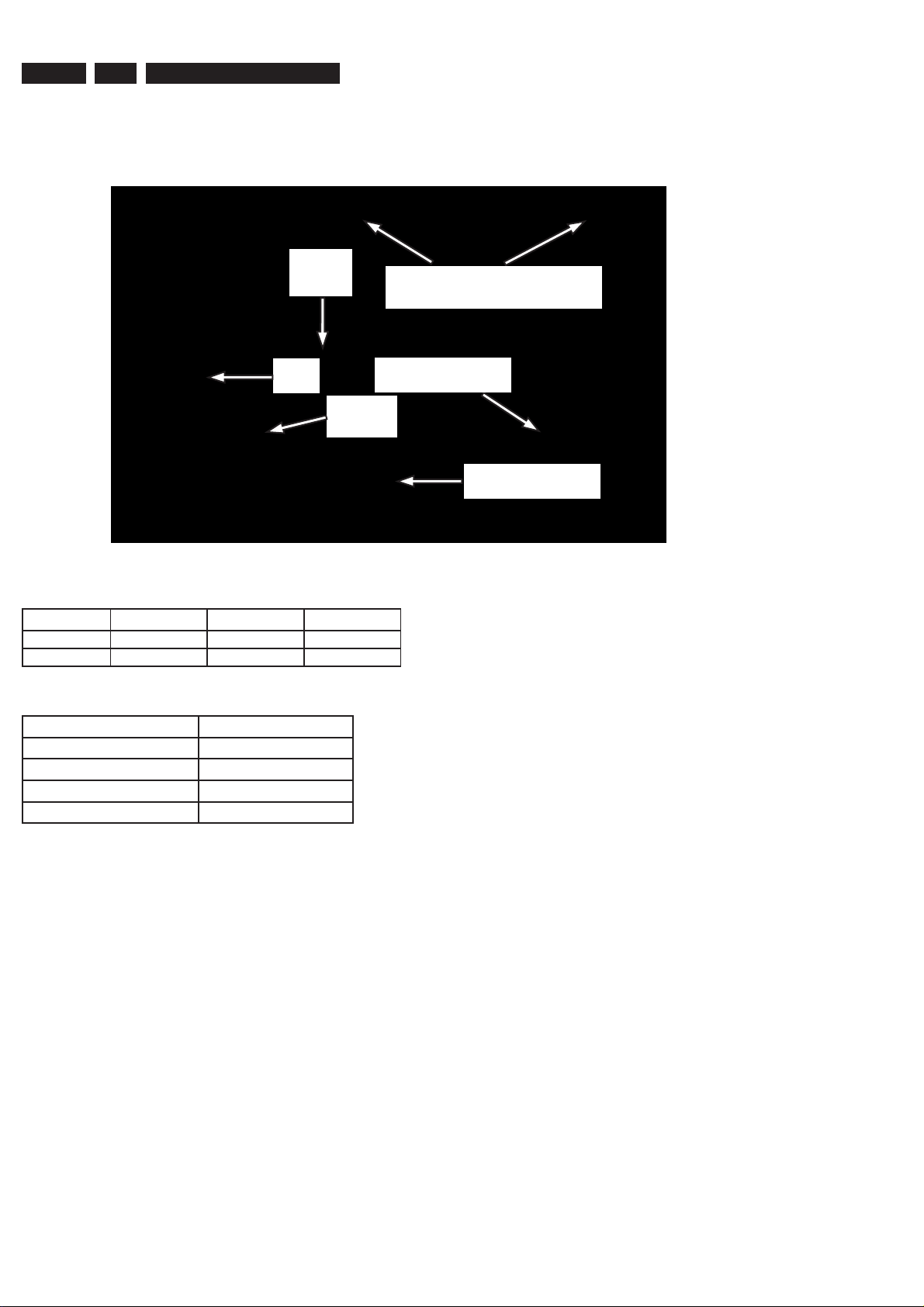
1.1 PCB Locations
Digital
Board
HDD
PSU
Board
1.2 Diversity Matrix
DVDR5350H DVDR7300H DVDR7310H
HDD capacity 160GB 250GB 250GB
HDMI – x x
1.3 Read / Write Speed
Type of Disc (Function) Disc Rotation Speed
Read Speed CD 7X CAV
Read Speed DVD 4X CAV
Write Speed DVD+R/+RW 2.4X ZCAV
Write Speed DVD-R/-RW 2X
1.4 General:
Mains voltage : 220V – 240V
Mains frequency : 50 Hz
Power consumption (record) : 40 W
Standby Power Consumption : < 4 W
Eco standby : < 3 W
Front Boards
(Behind the Front Plate)
HDMI Board
Analog Board
1.5.3 Receiver:
PLL tuning with AFC for optimum reception
Frequency range : 45.25 MHz – 857 MHz
Sensitivity at 40dB S/N
(video unweighted) : 60dBV at 75
1.5.4 Video Performance:
Channel 25 / 503,25 MHz,
Test pattern: PAL BG PHILIPS standard test pattern,
RF Level 74dBV, Measured on SCART 1
Frequency response : 0.1 MHz – 4 MHz ± 3dB
Group delay (0.1 MHz - 4.4 MHz) : 0 nsec ± 150 nsec
1.5.5 Audio Performance:
Audio Performance Analogue - HiFi:
Frequency response at SCART 1
(L+R) output : 100 Hz – 12 kHz / 0 ±
3dB
S/N Ratio (20Hz – 20kHz)
unweighted : 50dB
Harmonic distortion (1 kHz, ± 25
kHz deviation) : 1.5%
1.5 RF Tuner
Test equipment: Fluke 54200 TV Signal generator
Test streams: PAL BG Philips Standard test pattern
1.5.1 System
PAL B/G, PAL D/K, SECAM L/L’, PAL I
1.5.2 RF - Loop Through:
Frequency range : 45 MHz – 860 MHz
Gain: (ANT IN - ANT OUT) : -6dB to 0dB
Audio Performance NICAM:
Frequency response at SCART 1
(L+R) output : 40 Hz – 15 kHz / 0 ±
3dB
S/N Ratio (20Hz – 20kHz)
unweighted : 60dB
Harmonic distortion (1kHz, ± 25
kHz deviation) : 0.5%
Page 3

Technical Specifi
cations and Connection Facilities
3139 785 31532
1.
EN 3
1.5.6 Tuning
Automatic Search Tuning
Scanning time without RF signal : 3min. typical
Stop level (vision carrier) : 37dB/V
Maximum tuning error of a recalled
program : ± 100 kHz
Maximum tuning error (drift) during
operation : ± 100 kHz
Tuning Principle:
Automatic B, G, I, DK and L/L’ detection
Manual selection in “STORE” mode
1.6 Analog Inputs / Outputs
1.6.1 SCART 1 (Connected to TV)
Pin Signals:
1 Audio-out R 1.8V RMS
2 Audio-in R
3 Audio-out L 1.8V RMS
4 Audio GND
5 Blue / Chroma GND
6 Audio-in L
7 Blue-out 0.7Vpp ± 0.1V into 75
8 Function switch < 2V = TV
> 4.5V / < 7V = asp. Ratio 16:9 DVD
> 9.5V / < 12V = asp. Ratio 4:3 DVD
9 Green GND
10 P50 control not use
11 Green out 0.7Vpp ± 0.1V into 75
12 NC
13 Red / Chroma GND
14 Fast switch GND
15 Red-out / 0.7Vpp ± 0.1V into 75
Chroma-out 300mVpp ± 3dB
16 Fast switch
RGB / CVBS
or Y out < 0.4V into 75 = CVBS
>1V / < 3V into 75 = RGB
17 Y/CVBS-out GND
18 CVBS-in GND
19 CVBS-out / Y-out 1Vpp ± 0.1V into 75
20 CVBS-in
21 Shield
1.6.2 SCART 2 (Connected to AUX)
1.6.3 Audio/Video Front Input Connectors
Audio - Cinch
Input voltage : 2.2Vrms
Input impedance : > 10k
Video - Cinch
Input voltage : 1Vpp ± 3dB
Input impedance : 75
Video - YC (Hosiden)
According to IEC 933-5
Superimposed DC-level on pin 4 (load > 100k)
< 2.4V is detected as 4:3 aspect ratio
> 3.5V is detected as 16:9 aspect ratio
Input voltage Y : 1Vpp ± 3dB
Input impedance Y : 75
Input voltage C : 300mVpp ± 3dB
Input impedance C : 75
1.6.4 Out 1
Component Video Cinch Y/Pb/Pr
according EIO-770-I-A, EIA-770-2
Audio - Cinch
Output voltage : 2Vrms max.
Output impedance : > 10k
1.6.5 Out 2
Audio - Cinch
Output voltage : 2Vrms max.
Output impedance : > 10k
Video - Cinch
Output voltage : 1Vpp ± 3dB
Output impedance : 75
Video - YC (Hosiden)
According to IEC 933-5
Superimposed DC-level on pin 4 (load > 100k)
< 2.4V is detected as 4:3 aspect ratio
> 3.5V is detected as 16:9 aspect ratio
Output voltage Y : 1Vpp ± 3dB
Input impedance : 75
Output voltage C : 300mVpp ± 3dB
Input impedance : 75
Pin Signals:
1 Audio-out R 1.8V RMS
2 Audio-in R
3 Audio-out L 1.8V RMS
4 Audio GND
5 Blue / Chroma GND
6 Audio-in L
7 Blue-in
8 Function switch
9 Green GND
10 P50 control
11 Green-in
12 NC
13 Red / Chroma GND
14 Fast switch GND
15 Red-in /
Chroma-in
16 Fast switch
RGB / CVBS or Y in
17 CVBS-out GND
18 Y / CVBS-in GND
19 CVBS-out 1Vpp ± 0.1V into 75
20 CVBS-in / Y-in
21 Shield
1.7 Digital Inputs / Outputs
1.7.1 Digital Output
Digital Audio – Coaxial / Optical
LCM : according IEC 60958
MPEG 1, MPEG 2, AC3 : according IEC 61937
DTS : according IEC 61937 +
addendum
1.7.2 HDMI Output
Type A connector (19 pins)
1.7.3 Digital Video Input (IEEE 1394)
Implementation Standard according:
IEEE Std 1394-1995
IEC61883 - Part1
IEC61883 - Part 2 SD-DVCR (02-01-1997)
Specifi cation of consumer use digital VCR’s using 6.3mm
magnetic tape – dec.1994
Mechanical connection according to Annex of IEC 61883-1
Page 4

EN 4
1.7.4 G-Link (for IR-remote transmitting device)
Output voltage : 5 ± 0.5V (high level)
0.4 ± 0.3V (low level)
Output impedance : 150
1.
3139 785 31532
Technical Specifi
1.8 Video Performance
All outputs loaded with 75
SNR measurements over full bandwidth without weighting.
1.8.1 SCART (RGB)
SNR : 55dB on all output
Bandwidth : 4.8MHz -3dB
1.9 Audio Performance
1.9.1 Cinch Output Rear
Output voltage 2 channel mode : 2Vrms ± 2dB
Channel unbalance (1kHz) : < 0.22dB
Crosstalk 1kHz : > 100dB
Crosstalk 16Hz-20kHz : > 87dB
Frequency response 20Hz-20kHz : ± 0.5dB
Signal to noise ratio (unweighted) : > 85dB
Dynamic range 1kHz : > 83dB
Distortion and noise 1kHz : > 83dB
Distortion and noise 16Hz-20kHz : > 75dB
Intermodulation distortion : > 70dB
Mute : > 95dB
cations and Connection Facilities
1.9.2 Scart Audio
Output voltage 2 channel mode : 1.6Vrms ± 2dB
Channel unbalance (1kHz) : < 1dB
Crosstalk 1kHz : > 85dB
Crosstalk 16Hz-20kHz : > 70dB
Frequency response 20Hz-20kHz : ± 0.5dB
Signal to noise ratio (unweighted) : > 80dB
Dynamic range 1kHz : > 75dB
Distortion and noise 1kHz : > 75dB
Distortion and noise 16Hz-20kHz : > 50dB
Intermodulation distortion : > 70dB
Mute : > 80dB
1.10 Dimensions and Weight
Height of feet : 5.5mm
Apparatus tray closed : WxDxH:435x335x76mm
Apparatus tray open : WxDxH:435x472x76mm
Weight without packaging : 5kg
Weight with packaging : 8kg
1.11 Laser Output Power & Wavelength
1.11.1 DVD
Output power during reading : 0.8mW
Output power during writing : 20mW
Wavelength : 650nm
1.11.2 CD
Output power : 0.3mW
Wavelength : 780nm
Page 5
Safety Information, General Notes & Lead Free Requirements
3139 785 31532
2.
2. Safety Information, General Notes & Lead Free Requirements
EN 5
2.1 Safety
Instructions
2.1.1 General Safety
Safety regulations require that during a repair:
• Connect the unit to the mains via an isolation transformer.
• Replace safety components, indicated by the symbol ,
only by components identical to the original ones. Any
other component substitution (other than original type)
may increase risk of fi re or electrical shock hazard.
Safety regulations require that after a repair, you must return
the unit in its original condition. Pay, in particular, attention to
the following points:
• Route the wires/cables correctly, and fi x them with the
mounted cable clamps.
• Check the insulation of the mains lead for external
damage.
• Check the electrical DC resistance between the mains
plug and the secondary side:
1. Unplug the mains cord, and connect a wire between
the two pins of the mains plug.
2. Set the mains switch to the ‘on’ position (keep the
mains cord unplugged!).
3. Measure the resistance value between the mains
plug and the front panel, controls, and chassis
bottom.
4. Repair or correct unit when the resistance
measurement is less than 1 M.
5. Verify this, before you return the unit to the customer/
user (ref. UL-standard no. 1492).
6. Switch the unit ‘off’, and remove the wire between the
two pins of the mains plug.
2.1.2 Laser Safety
This unit employs a laser. Only qualifi ed service personnel
may remove the cover, or attempt to service this device (due
to possible eye injury).
2.2 Warnings
2.2.1 General
• All ICs and many other semiconductors are susceptible to
electrostatic discharges (ESD, ). Careless handling
during repair can reduce life drastically. Make sure that,
during repair, you are at the same potential as the mass
of the set by a wristband with resistance. Keep
components and tools at this same potential.
Available ESD protection equipment:
– Complete kit ESD3 (small tablemat, wristband,
connection box, extension cable and earth cable)
4822 310 10671.
– Wristband tester 4822 344 13999.
• Be careful during measurements in the live voltage
section. The primary side of the power supply, including
the heatsink, carries live mains voltage when you
connect the player to the mains (even when the
player is ‘off’!). It is possible to touch copper tracks and/
or components in this unshielded primary area, when
you service the player. Service personnel must take
precautions to prevent touching this area or components
in this area. A ‘lightning stroke’ and a stripe-marked
printing on the printed wiring board, indicate the primary
side of the power supply.
• Never replace modules, or components, while the unit is
‘on’.
2.2.2 Laser
• The use of optical instruments with this product, will
increase eye hazard.
• Only qualifi ed service personnel may remove the cover or
attempt to service this device, due to possible eye injury.
• Repair handling should take place as much as possible
with a disc loaded inside the player.
• Text below is placed inside the unit, on the laser cover
shield:
Laser Device Unit
Type : Semiconductor laser
GaAlAs
Wavelength : 650 nm (DVD)
: 780 nm (VCD/CD)
Output Power : 20 mW
(DVD+RW writing)
: 0.8 mW
(DVD reading)
: 0.3 mW
(VCD/CD reading)
Beam divergence : 60 degree
CLASS 1
LASER PRODUCT
Figure 2-1
Note: Use of controls or adjustments or performance of
procedure other than those specifi ed herein, may result in
hazardous radiation exposure. Avoid direct exposure to beam.
CAUTION VISIBLE AND INVISIBLE LASER RADIATION WHEN OPEN AVOID EXPOSURE TO BEAM
ADVARSEL SYNLIG OG USYNLIG LASERSTRÅLING VED ÅBNING UNDGÅ UDSÆTTELSE FOR STRÅLING
ADVARSEL SYNLIG OG USYNLIG LASERSTRÅLING NÅR DEKSEL ÅPNES UNNGÅ EKSPONERING FOR STRÅLEN
VARNING SYNLIG OCH OSYNLIG LASERSTRÅLNING NÄR DENNA DEL ÄR ÖPPNAD BETRAKTA EJ STRÅLEN
VARO! AVATTAESSA OLET ALTTIINA NÄKYVÄLLE JA NÄKYMÄTTÖMÄLLE LASER SÄTEILYLLE. ÄLÄ KATSO SÄTEESEEN
VORSICHT SICHTBARE UND UNSICHTBARE LASERSTRAHLUNG WENN ABDECKUNG GEÖFFNET NICHT DEM STRAHL AUSSETSEN
DANGER VISIBLE AND INVISIBLE LASER RADIATION WHEN OPEN AVOID DIRECT EXPOSURE TO BEAM
ATTENTION RAYONNEMENT LASER VISIBLE ET INVISIBLE EN CAS D’OUVERTURE EXPOSITION DANGEREUSE AU FAISCEAU
Figure 2-2
Page 6
EN 6
2.
3139 785 31532
Safety Information, General Notes & Lead Free Requirements
2.3 Lead Free Requirement
Information about Lead-free produced sets
Philips CE is starting production of lead-free sets from
1.1.2005 onwards.
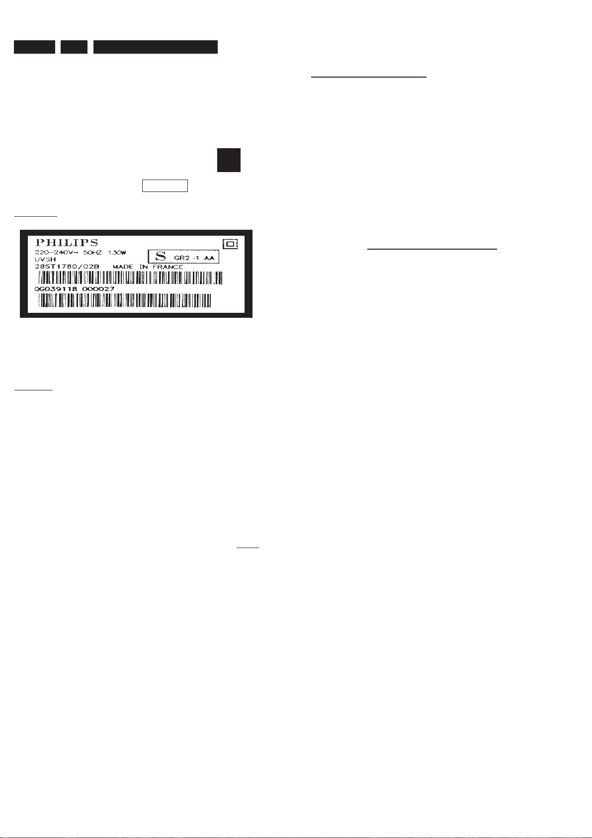
INDENTIFICATION:
Regardless of special logo (not always indicated)
One must treat all sets from 1 Jan 2005 onwards, according
next rules.
Example S/N:
Bottom line of typeplate gives a 14-digit S/N. Digit 5&6 is the year, digit 7&8 is
the week number, so in this case 1991 wk 18
So from 0501 onwards = from 1 Jan 2005 onwards
• Special information for BGA-ICs:
Do not re-use BGAs at all.
• For sets produced before 1.1.2005 (except products of
• On our website www.atyourservice.ce.Philips.com you
BGA-de-/soldering (+ baking instructions)
Heating-profi les of BGAs and other ICs used in Philips-sets
You will fi nd this and more technical information within the
For additional questions please contact your local repair-helpdesk.
- always use the 12nc-recognizable soldering temperature
profi le of the specifi c BGA (for de-soldering always use the
lead-free temperature profi le, in case of doubt)
- lead free BGA-ICs will be delivered in so-called ‘dry-
packaging’ (sealed pack including a silica gel pack) to
protect the IC against moisture. After opening, dependent
of MSL-level seen on indicator-label in the bag, the
BGA-IC possibly still has to be baked dry. (MSL=Moisture
Sensitivity Level). This will be communicated via AYS-
website.
2004), containing leaded solder-alloy and components,
all needed spare-parts will be available till the end of the
service-period. For repair of such sets nothing changes.
fi nd more information to:
“magazine”, chapter “workshop news”.
Important note: In fact also products of year 2004 must be treated in this way as long as you
avoid mixing solder-alloys (leaded/ lead-free). So best to always use SAC305 and the higher
temperatures belong to this.
Due to lead-free technology some rules have to be respected by the
workshop during a repair:
• Use only lead-free solder alloy Philips SAC305 with order
• Use only adequate solder tools applicable for lead-free
o To reach at least a solder-temperature of 400°C,
o To stabilize the adjusted temperature at the solder-tip
o To exchange solder-tips for different applications.
• Adjust your solder tool so that a temperature around 360°C
• Mix of lead-free solder alloy / parts with leaded solder alloy
• Use only original spare-parts listed in the Service-Manuals.
code 0622 149 00106. If lead-free solder-pate is required,
please contact the manufacturer of your solder-equipment.
In general use of solder-paste within workshops should be
avoided because paste is not easy to store and to handle.
solder alloy. The solder tool must be able
– 380°C is reached and stabilized at the solder joint.
Heating-time of the solder-joint should not exceed ~ 4 sec.
Avoid temperatures above 400°C otherwise wear-out of
tips will rise drastically and fl ux-fl uid will be destroyed. To
avoid wear-out of tips switch off un-used equipment, or
reduce heat.
/ parts is possible but PHILIPS recommends strongly to
avoid mixed solder alloy types (leaded and lead-free).
If one cannot avoid or does not know whether product is
lead-free, clean carefully the solder-joint from old solder
alloy and re-solder with new solder alloy (SAC305).
Not listed standard-material (commodities) has to be
purchased at external companies.
Page 7
Directions For Use
From
a
n off-
a
ir
a
nt
e
nn
a
or
cable
b
o
x
Television (rear
)
Phili
p
s Recorder
(
rear
)
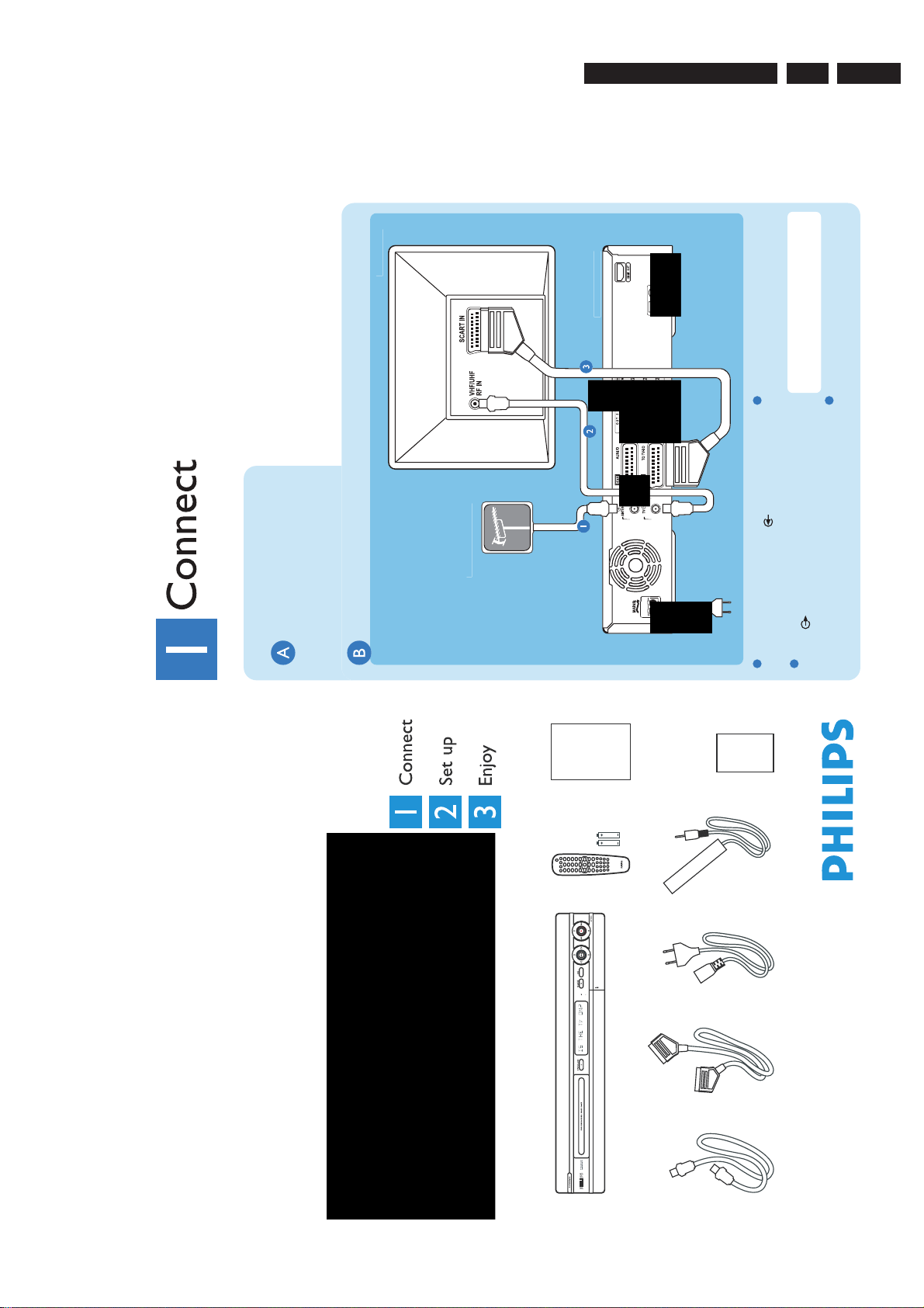
Basic connection
Before connecting
Unplug the antenna cable that is currently
connected to your TV.
Connecting
1
Disconnect the antenna cable from your TV
and connect it to the ANTENNA socket
on this recorder.
2
Use the supplied RF coaxial cable to connect
the TV socket on this recorder to the
Antenna In socket on your TV.
3
Use the supplied scart cable to connect the
EXT1 TO TV-I/O Scart socket on this
recorder to the SCART IN socket on your TV.
Note See the accompanying user manual for
others possible connection (e.g. HDMI,
Component Video).
4
Connect the power cable from the recorder
to an AC power outlet.
Start with the 'Basic connection'.
If you have a VCR, follow the instructions for ‘Connection with VCR or similar device’.
If you have a set-top box, follow the instructions for ‘Connection with set-top box’.
3139 785 31532
3.
3. Directions For Use
The following except of the Quick Use Guide serves as an introduction to the set.
The Complete Direction for the Use can be downloaded in different languages from the internet site of Philips Customer care Center:
www.p4c.philips.com
EN 7
DVDR 5350H
DVDR 7300H
HDD & DVD Player / Recorder
Quick Start Guide
Quick start guideRemote control
DVD recorder/hard disk
and 2 batteries
What’s in the Box
User manual
& transmitterPower cable
G-LINK cable
RF coaxial cable Scart cable
Page 8
EN 8
(
)
C
o
s
ar
(
)
g
r
p
x
t
a
s
tte
(
)
o
sou
ce
3.
3139 785 31532
Directions For Use
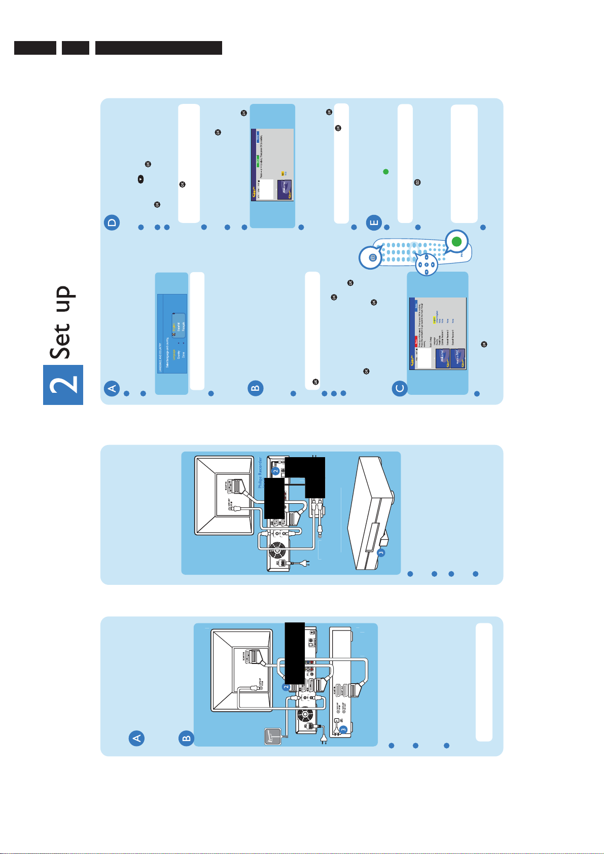
Setup External Receiver 1
Has the External Receiver 1 changed to Programme
Number 101?
system’s host
+
+
Install the set-top box
Press DOWN to select ‘External
If you do not have a set-top box, skip ‘D’ and go
to ‘E’.
1
Finding the viewing channel
The recorder will display ‘IS THE TV ON?’.
Press STANDBY-ON on the recorder.
Switch on the TV.
1
2
Connection with set-top box
Your new Philips Recorder provides a G-LINK
transmitter which allows you to control the
tuner of the set-top box (satellite receiver, cable
TV box) through the GUIDE Plus+ system. You
Receiver 1’ and press .
You should see the { EASY SETUP } menu.
Press again to continue.3 Select the type of reception, service provider
2
can record the TV programmes that are received
through the set-top box.
Note Press to go to the next screen.
Select { None } if none of the entries are
applicable.
and brand name of the connected set-top box.
Select the recorder socket through which
4
Note If connected to your VCR, make sure it
is turned off before proceeding.
rear
Television
Connecting
your set-top box is connected (e.g. 'EXT2' for
EXT 2 AUX-I/O socket) and press .
number 02 on the set-top box.
Turn on your set-top box and select channel
5
your TV's remote control repeatedly (or AV,
SELECT button) until you see the menu. This
is the correct viewing channel for the recorder.
If not, press the Channel Down button on
3
Read the instructions on the TV and press .
6
Start basic setup
set-top box’s channel through the G-LINK
transmitter. If the set-top box has switched to
the same programme number as displayed on
the TV, select { Yes } in the menu and press .
The recorder will now attempt to change the
7
Note Select { Done } in the menu and press
to go to the next screen.
country and the TV shape.
Select the desired menu language, your
Use the recorder's remote control and follow
the on-screen instructions to complete the
installation.
1
Activate automatic channel search. 3 Check the date and time and press .4 To continue with the GUIDE Plus+
2
r
T
Note If not, select { No } and press to try a
different code.
Your set-top box is now installed.
8
GUIDE
installation, select { Continue } and press .
press . Wait until the recorder has finished
Otherwise, select { Do not install now } and
bo
set-to
of G-LINK transmitte
Positionin
Load the TV listing data
Note To switch the GUIDE Plus
channel manually, go to { Host Channel Setup }.
Press the GREEN button to leave the
menu.
1
system
+
Install the GUIDE Plus
initialising the system, then press again.
r
mi
n
r
-LINK
Follow step 1 to 4 of 'Basic connection' to
1
Note If you tune to your Host Channel
before going to 'standby' mode, this recorder
will start immediately to download the TV
listings data.
Check the { Editor } screen the next day to
ensure the source and programme numbers
system. Leave the recorder in 'standby' mode
and turn 'on' the set-top box overnight to
collect the TV listing data, this may take up to
24 hours.
Press GUIDE to exit the GUIDE Plus
2
connect this recorder before you proceed to
step 2 below.
G-LINK socket on this recorder.
set-top box in such a way that it can acquire
Place the G-LINK transmitter in front of your
3
the signal broadcasted by the transmitter.
Connect the supplied G-LINK cable to the
2
are matching for all channels.
3
To change, press and follow the on-screen
instructions.
Enter your language, country and postal code
1
box to an AC power outlet.
Connect the power cable from the set-top
4
rear
Television
Before connecting
Connection with VCR
or similar device
Your new Philips Recorder replaces the VCR for
your recording needs. First, unplug all the
connections from your VCR.
Connecting
From an off-air
antenna or
cable box
imil
rear
r
R
V
device
Note In this setup, the VCR cannot record
connect this recorder before you proceed to
step 2 below.
connect the EXT2 AUX-I/O Scart socket on
this recorder to the SCART OUT socket on
your VCR.
Follow step 1 to 4 of 'Basic connection' to
Use another scart cable (not supplied) to
1
2
AC power outlet.
Connect the power cable from the VCR to an
3
TV programmes.
Page 9
Directions For Use
3139 785 31532
3.
2005 © Koninklijke Philips N.V.
All rights reserved.
EN 9
12 NC 31 39 246 18511
www.philips.com
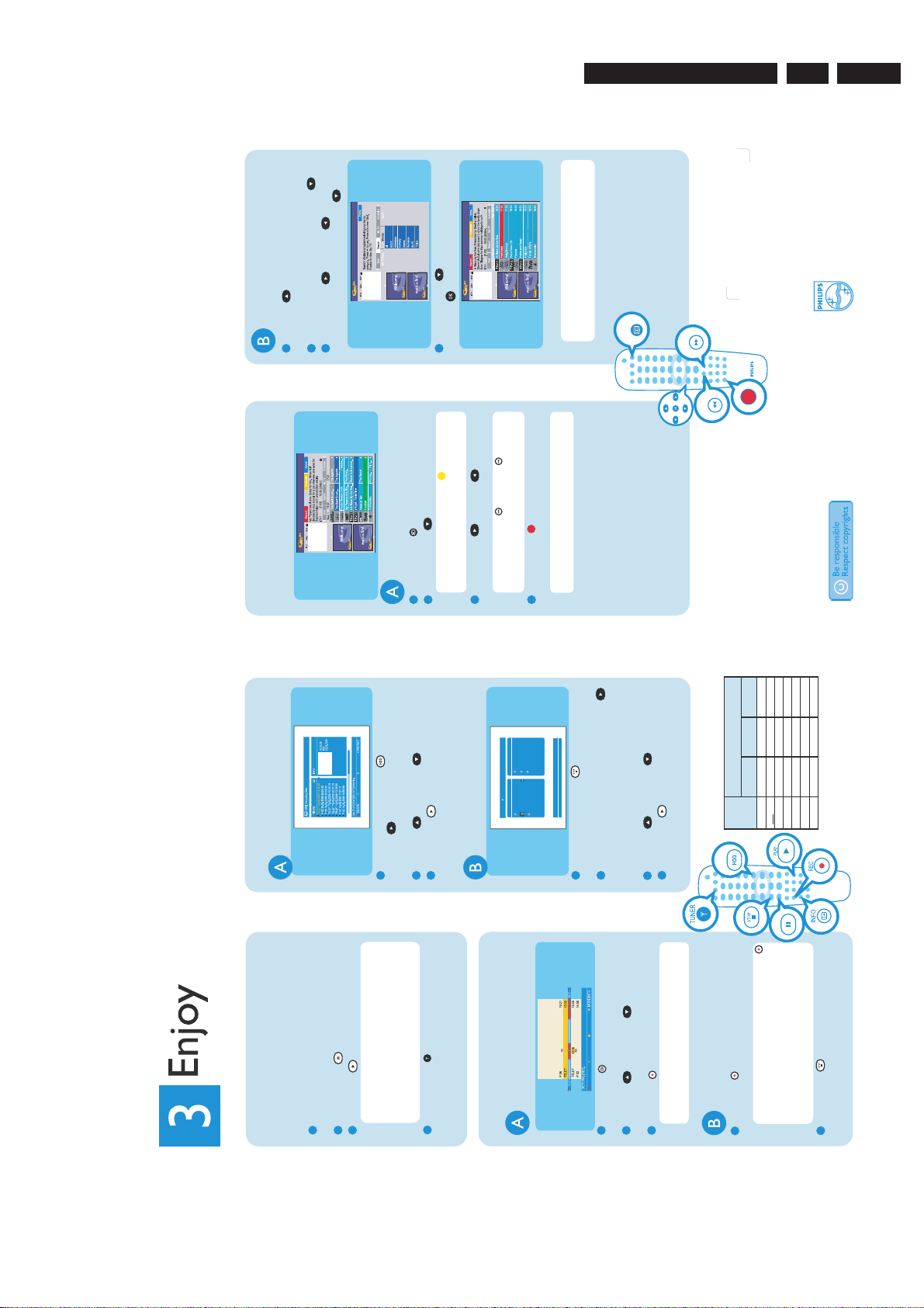
Search TV programmes
search category and press DOWN .
(‘Grid’, ‘Search’, ‘My TV’, etc.)
Press UP until you highlight the menu bar
Highlight { Search } and press DOWN .3 Press RIGHT or LEFT to select a
1
2
system
+
Using the GUIDE Plus
Make sure that the TV listing data download is
completed.
COPY
From the hard disk
Start playback
Press HDD-BROWSER , then press
1
Record TV programmes
Press GUIDE .2 Press DOWN to select a TV channel.
1
RIGHT until you see the { TITLES } and
{ INFO } menus.
Press UP or DOWN to select a title.3 Press PLAY to start playback.
2
and press to start the search.
Press DOWN to select a sub-category
4
Note Press the YELLOW to see an
overview of all the available channels and
choose from there.
TV programme.
Press RIGHT or LEFT to select a
3
From a disc
Note Press DAY- or DAY+ to go
directly to a day before or the next day TV
listings.
Press the RED button to set the
4
Video
Audio
Photo
CONTENT
Hard Disk
Disc Tray
Disc Library
SOURCES 1/3
Note If ‘No programme found’ appears, that
Note You can store up to 25 programmes for
recording.
highlighted programme for recording.
[BROWSER]
means there are no programmes of that
category for that day.
opens, load in a disc and close the disc tray.
until you see the { TITLES }, { TRACKS } or
Hold down the STOP until the disc tray
1
{ PHOTO ROLLS } menu, depending on the
If the content menu appears, press RIGHT
2
GUIDE
+
DAY
DAY
system
+
Need help?
GUIDE Plus
Go to www.europe.guideplus.com
User Manual
See the user manual that came with your Philips
Recorder
Online
Go to www.philips.com/support
DVD+R
Double Layer
1hr 55mins
3hr 40mins
4hr 35mins
5hr 30mins
7hr 20mins
11h 05mins
14h 45mins
122.53468
DVD±R/
DVD±RW
4795119
143
191
287
SLP
400
SEP
HDD
(250 GB)
Hours of recordings can be stored on the
HDD or an empty DVD recordable disc.
HQSPSPPLPEP
Record
Mode
disc type.
Press PLAY to start playback.
Press UP or DOWN to select a title.
3
4
BROWSER
Watch TV - Pause live TV
Your Philips Recorder allows you to control the TV
programme. You can PAUSE it as if you were in
Turn on your recorder and press CHANNEL
control of the live broadcast.
1
Note When the recorder is turned on, the
+/- to select a TV programme.
Press PAUSE to suspend it.
Press PLAY to continue.
2
3
programme you are watching will be stored in
the temporary hard disk storage. When you
switch the recorder to another input signal (e.g.
CAM) or to standby mode, the programme will
be erased.
Press TUNER to return to the live
4
broadcast.
Contents in the temporary
Record to hard disk
HDD storage
BACK
Note The title will be marked in red and the
stored in the hard disk storage.
Press INFO to see what is temporarily
1
2
recording will only take effect when you turn
title you want to record.
Press UP or DOWN to choose the
Press REC to record the title.
3
off the recorder.
Current TV programme
up to 6 hours.
Press REC to start recording. It can record
1
PAUSE
system is available, ‘Record
+
Note To set the recording time, press REC
repeatedly to extend the recording time in 30
minutes increments for up to 6 hours.
If the GUIDE Plus
1 program’ is displayed and the current
programme will be recorded.
Press STOP to stop the recording
2
immediately.
Page 10

EN 10
4.
3139 785 31532
Mechanical Instructions
4. Mechanical Instructions
Note: The position numbers given here refers to the
Exploded view on chapter 10.
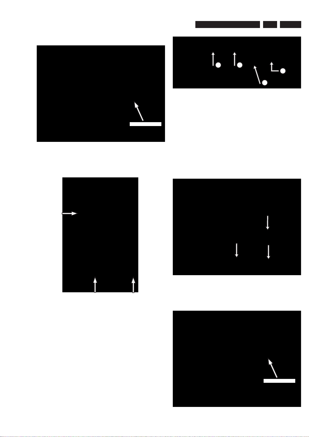
4.1 Dismantling of the DVD Tray cover
1) Insert a screw-driver into the slot provided at the bottom
of the set and push in the direction as shown in
picture 4-1 to unlock before sliding the Tray cover
assembly out.
2
Figure 4-1: Remove DVDR tray
2) Remove the Tray cover assembly as shown in
Figure 4-2.
5) Remove 6 screws to loosen the Front plate to reach
the Front board service position (see Figure 4-4).
1
Figure 4-4: Front Board Service position
4.3 Dismantling of the Digital Board / HDD
1) Remove 4 screws to loosen the Digital Board as
shown in Figure 4-5.
Figure 4-2: Remove tray cover assembly
4.2 Dismantling of the Front Panel assembly
1) Remove 7 screws to loosen Top cover.
2) Remove the DVD Tray cover as given in step 4-1.
3) Loosen the Digital Board & HDD as given in step 4-3.
4) Loosen 3 screws and 2 catches as shown in Figure 4-3
to separate the Front panel assembly from the Frame
assembly.
Figure 4-3
Figure 4-5: Digital Board
Page 11
Mechanical Instructions
2) Service position for Digital Board is given in Figure 4-6.
3139 785 31532
4.
EN 11
Insulation Sheet
Figure 4-6: Digital Board Service Position
1) Remove the 3 screws to loosen the HDD assembly
as shown in Figure 4-7.
4
4) Remove 4 screws 247,248,249,250 to separate the
Bracket HDD from the HDD.
Note: Screws 247,248,249,250 are special type of screws
that must be replaced only with those specifi ed in the Service
Parts list on Chapter 10.
3
2
1
Figure 4-8
4.4 Dismantling of the PSU Board
1) Remove 3 mounting screw on PSU Board as shown in
fi gure 4-9.
Figure 4-7
1) Unscrew screw labelled 1 in fi gure 4-8.
2) Lift up the harddisk in the arrow labeled 3 and 4 in
fi gure 4-8.
3) Slide out in the direction of the arrow labeled 2 in
fi gure 4-8.
Figure 4-9: PSU remove screw
2) Service position for the PSU Board as shown in fi gure
4-10.
Insulation Sheet
Figure 4-10: PSU Board Service Position
Page 12
EN 12
4.
3139 785 31532
Mechanical Instructions
Dismantling of the Basic Engine (Drive D4.3)
4.5
1) Remove 4 screws to loosen the Basic Engine assembly
as shown in Figure 4-11.
Figure 4-11
2) Remove 2 screws to loosen the Bracket Loader and
uncatch the Dust cover assembly.
3) Remove 4 screws to loosen the Cover of the Basic
Engine to reach Service position Figure 4-12.
4.6 Dismantling of the Analog Board
1) Remove the Basic Engine assembly as given in step 4.4.
2) Remove the HDMI board as shown in Figure 4-13.
Figure 4-13
3) Remove 15 screws on the Rear panel as shown in
Figure 4-13.
Insulation Sheet
Figure 4-12: Basic Engine Service Position
Figure 4-14
4) Remove 3 screw mounting the Analog Board to the
Frame Assembly as given in Figure 4-13.
Figure 4-15
5) Service position is achieved by placing the Analog Board
in the vertical position as shown in Figure 4-16.
Page 13

Mechanical Instructions
Figure 4-16: Analog Board Service Position
4.7 Dismantling of the HDMI Board
1) Remove the HDMI board as shown in Figure 4-13.
2) Service Position of HDMI board given in Figure 4-17.
3139 785 31532
4.
EN 13
Figure 4-17: HDMI Board Service Position
Page 14

EN 14
5.
3139 785 31532
Firmware Upgrading & Diagnostic Software
5. Firmware Upgrading & Diagnostic Software
5.1 Firmware Upgrading
A. Preparation to upgrade fi rmware:
1. Unzip the zip-archive fi le
2. Start the CD Burning software and create a new CD project (data disc) with the following settings:
File system: Joliet
Format: MODE 2: CDROM XA
Recording mode: SINGLE SESSION (TRACK-AT-ONCE), FINALIZED CD
Note: Long fi le name is necessary for the preparation of the upgrade disc
3. Place the content of the zip-archive into the root directory of the new CD project.
4. Burn the data onto a blank CDR or CD-RW
B. Procedure to apply the fi rmware upgrade:
1. Hold the <Record> + <Next> buttons down and Power up the set.
2. The tray opens and set will display:
DOWNLOAD −>……….INSERT DISC
3. Insert the prepared Upgrade CDROM and close the tray.
4. The set will display:
INIT DISC −> DOWNLOAD −>……….
The whole process takes less than 10 minutes
Note: Do not press any buttons or interrupt the mains supply during the upgrading process, otherwise the set may becomes
defective.
5. When the upgrade is completed the tray will open automatically and the set will display:
REMOVE DISC
6. Close the tray and the set will display:
DONE
7. The set will go into Standby mode.
C. How to read out the fi rmware version to confi rm set has been upgraded:
1. Power up the set.
2. Press <System> button on the Remote control and select {Setup} option
3. Press <Right> button to select {System}
4. The set will prompt you about clearing the Time Shift Buffer
5. Select {Yes} and press <OK> button
6. Press <Down> button several times to select {Version info}
7. Press <OK> button
8. The TV connected to the set will display:
DIF05_5/56299AN SV11201
BE 43.2.13 ASP1,18,1,10FP
SIT5300-FNAC6-S3_299-F536_B1
20050909-1857 dev sxc
EPG:DPMS:P_DPM
9. Press <System> button to exit
Page 15
Firmware Upgrading & Diagnostic Software
Diagnostic Software
3139 785 31532
5.
EN 15
Due to the complexity of the DVD recorder, the time to find a
defect in the recorder can become long. To reduce this time,
the recorder has been equipped with Diagnostic and Service
software (DS). The DS offers functionality to diagnose the
DVDR hardware and tests the following:
• Interconnections between components
• Accessibility of components
• Functionality of the audio and video paths
This functionality can be accessed via several interfaces:
1. End user/Dealer script interface
2. Command Interface
5.2 End User/Dealer Script Interface
5.2.1 Description
The End user/Dealer script interface gives a diagnosis on a
stand alone DVD recorder. During this mode, a number of
hardware tests (nuclei) are automatically executed to check if
the recorder is faulty. The diagnosis is simply a "fail" or "pass"
message. If the message "FAIL" appears on the display, there
is apparently a failure in the recorder. If the message "PASS"
appears, the nuclei in this mode have been executed
successfully. There can be still a failure in the recorder
because the nuclei in this mode don't cover the complete
functionality of the recorder.
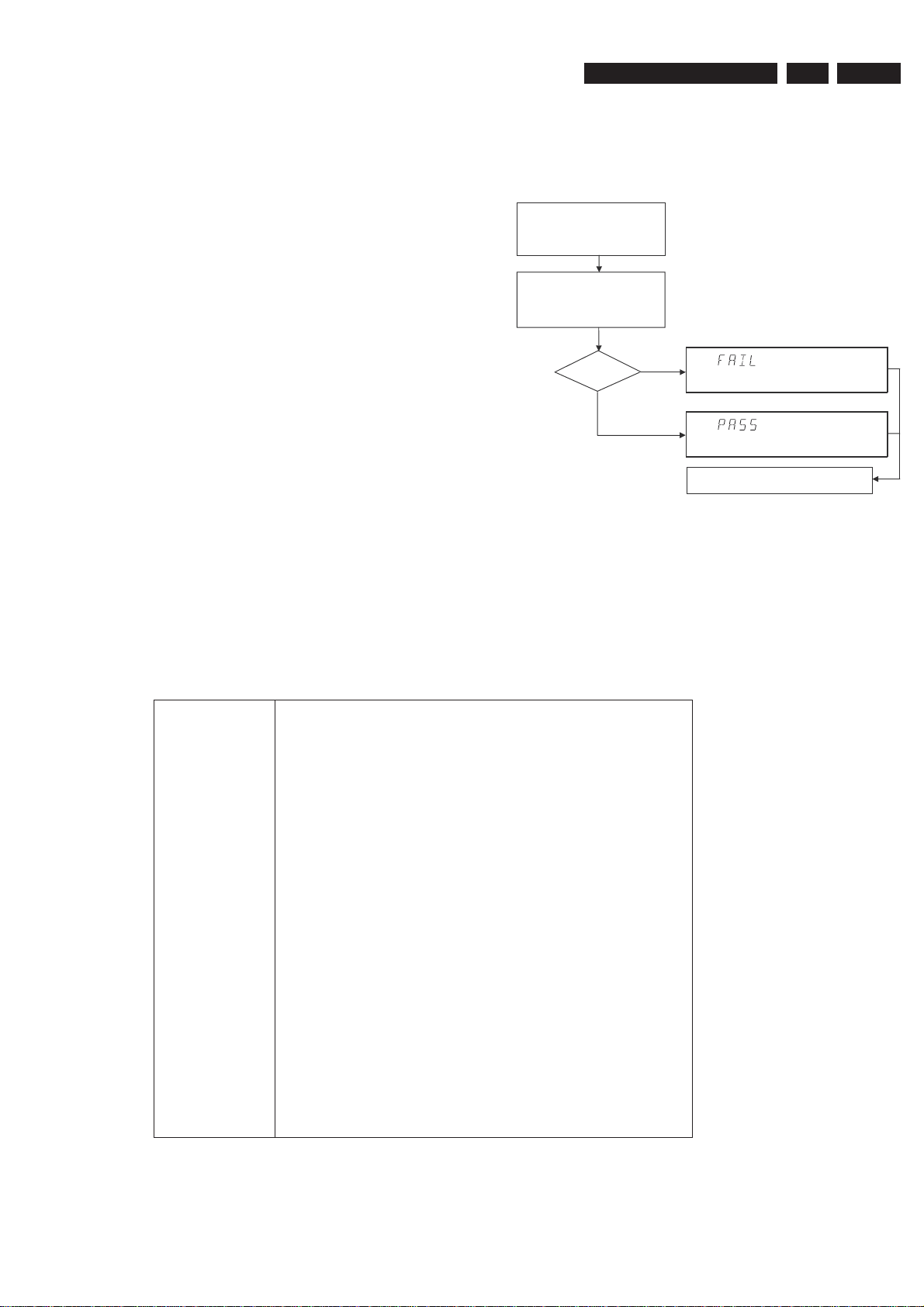
5.2.2 Structure
Unplug the power cord
Hold key <PLAY> pressed
while you plug the recorder
During the test, the display will show
the a sequence of nuclei under test
SET O.K.?
NO
YES
To exit DEALER SCRIPT, unplug the power cord
Figure 5-1
The End use/Dealer script executes all diagnostic nuclei that
do not need any user interaction and are meaningful on a
standalone DVD recorder.
TR 18029_001
120304
5.2.3 Contents
Included tests: 1.DS_ANAB_COM MUN ICATIONECHO_NU C
2.DS_DCB_COMMUNICATIONECHO_NUC
3. DS_BROM_COMMUNICATION_NUC
4. DS_SYS_SETTINGSDISPLAY_NUC
5. DS_CHR_DEVTYPEGET_NUC
6. DS_CHR_INT_PIC_NUC
7. DS_CHR_DMA_NUC
8. DS_BROM_WRITEREAD_NUC
9. DS_NVRAM_COMMUNICATION_NUC
10. DS_NVRAM_WRITEREAD_NUC
11. DS_SDRAM_WRITEREADFAST_NUC
12. DS_FLASH_WRITEREAD_NUC
13.DS_FLASH_CHECKSUMPROGRAM_NUC
14.DS_SYS_HARDWAREVERSIONGET_NUC
15. DS_VIP_DEVTYPEGET_NUC
16. DS_VIP_COMMUNICATION_NUC
17. DS_DVIO_LINKDEVTYPEGET_NUC
18. DS_DVIO_PHYDEVTYPEGET_NUC
19. DS_DVIO_LINKCOMMUNICATION_NUC
20. DS_DVIO_PHYCOMMUNICATION_NUC
21.DS_PSCAN_COMMUNICATIONDENC_NUC
22.DS_PSCAN_COMMUNICATIONDEINTERLACER_NUC
23. DS_BE_COMMUNICATIONECHO_NUC
24.DS_ANAB_COMMUNICATIONIICNVRAM_NUC
25.DS_ANAB_COMMUNICATIONIICTUNER_NUC
26.DS_ANAB_COMMUNICATIONIICSOUNDPROCESSOR_NUC
27.DS_ANAB_COMMUNICATIONIICAVSELECTOR_NUC
28. DS_ANAB_CHECKSUMPROGRAM_NUC
Page 16
EN 16
5.
3139 785 31532
5.3 Player Script Interface
Virgin mode
5.3.1
Firmware Upgrading & Diagnostic Software
5.4.2 Error Handling
If you want that the recorder starts up in Virgin mode, follow this
procedure:
• Unplug the recorder
• plug the recorder again while you keep the STAND BY/ON
key pressed
• the set starts up in Virgin mode.
5.4 Menu and Command Mode Interface
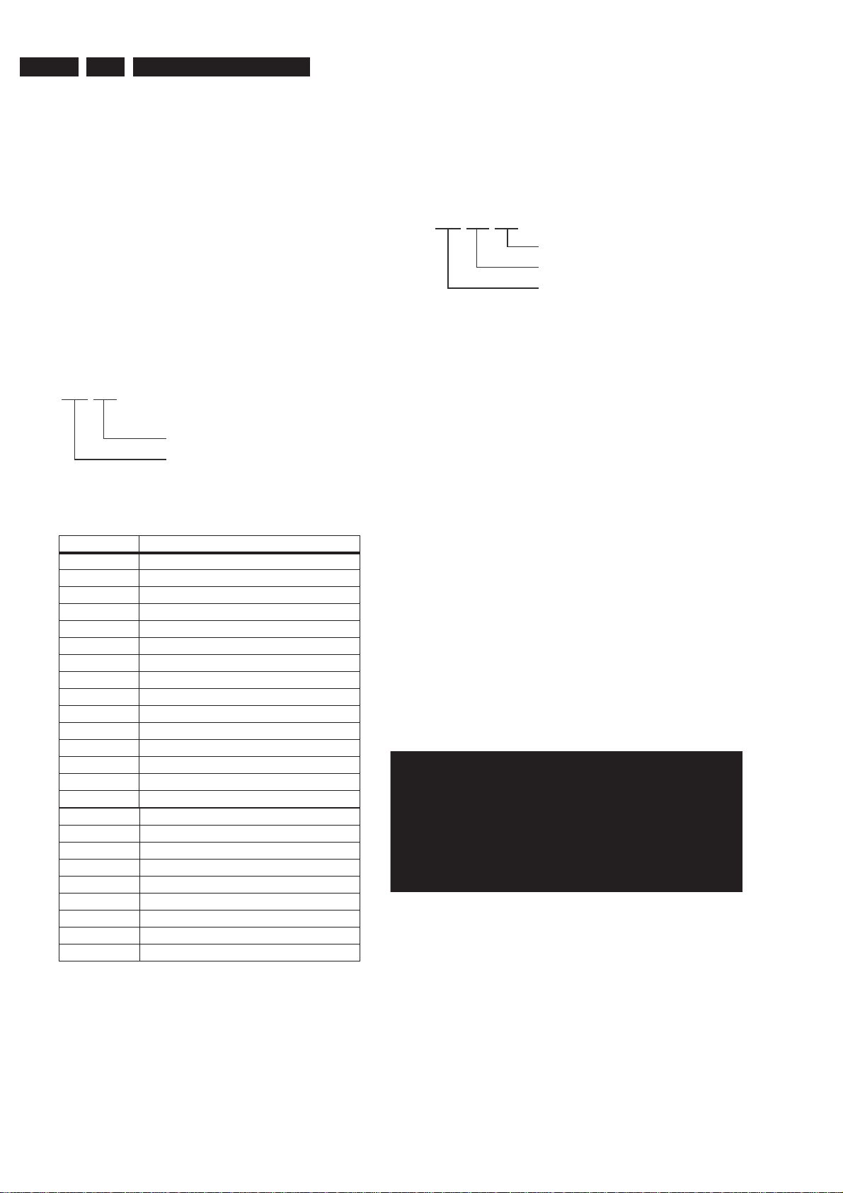
5.4.1 Nuclei Numeration
Each nucleus has a unique number of four digits. This number
is the input of the command mode.
[ XX YY ]
Nucleus number
Nucleus group number
Figure 5-3
Group number Group name
0 Scripts
1 Codec (e.g. Chrysalis, Leco)
2 Boot EEPROM
3NVRAM
4 SDRAM
5 Flash
6 Video Input Processor
7DVIO
8 Progressive Scan
9 Basic Engine
10* Display and Control Board
11* Analogue Board
12 System
13 Electronic Program Guide Board
14* PCMCIA
15 HDMI
16 Analogue Slave Processor
17 Analogue Board EEPROM
18 Video Matrix
19 Audio Matrix
20 Front End
21 Hard Disk
22* Di
23* USB
* Not applicable for DVDR5350H, DVDR7300H
and DVDR7310H Ranges
gital Terrestrial Tuner Module
CL 06532152_012.eps
051200
Each nucleus returns an error code. This code contains six
numerals, which means:
[ XX YY ZZ ]
Error code
Nucleus number
Nucleus group number
Figure 5-4
The nucleus group numbers and nucleus numbers are the
same as above.
5.4.3 Command Mode Interface
Set-Up Physical Interface Components
Hardware required:
• Service PC
• one free COM port on the Service PC
• special cable to connect DVD recorder to Service PC
The service PC must have a terminal emulation program (e.g.
Hyperterminal) installed and must have a free COM port (e.g.
COM1). Activate the terminal emulation program and check
that the port settings for the free COM port are: 19200 bps, 8
data bits, no parity, 1 stop bit and no flow control. The free COM
port must be connected via a special cable to the RS232 port
of the DVD recorder. This special cable will also connect the
test pin, which is available on the connector, to ground (i.e.
activate test pin).
Code number of PC interface cable: 3122 785 90017
Activation of Diagnostic Software
1. Pull the mains cord from the recorder and reconnect it
again (reboot).
2. The next welcome message will appear on the PC:
Welcome screen D&S program
Figure 5-5
Now, the prompt 'DS:>' will appear. The diagnostic software is
now ready to receive commands. The commands that can be
given are the numbers of the nuclei. If you see above shown
screen, continue with paragraph 'Nuclei Codes'.
CL 06532152_013.eps
051200
Page 17

Firmware Upgrading & Diagnostic Software
3139 785 31532
5.
EN 17
3. It is possible that the next messages will appear when
starting the DVD+RW for the first time
Error messages D&S program
Figure 5-6a
Error messages D&S program
Enter "Y" to program a safe string. With this automatically
generated string the board will work in principle but it has to be
checked if all board settings were detected correctly.
Diversity String Input
4. Execute nucleus 1226 to enter the string. Please see
chapter 8 for details
Nucleus 1226 execution with string
Figure 5-7
5. To check if the hardware info is filled correctly, you can
execute nucleus 1228.
Nucleus 1228 info example
Figure 5-6b
In these cases, the boot EEPROM of the Digital Board does not
contain the required string with the hardware information. To
update the Digital Board with the correct string, nucleus 1226
must be executed.
See next section 'Diversity String Input'.
There can also be the next error message.
Figure 5-8
6. Exit the 'Terminal' program.
Figure 5-6c
7. Reboot the DVD recorder to allow the software to start.
Page 18

EN 18
Command overview Digital Board
Below you will find an overview of the nuclei, their numbers,
and their error codes. This overview is preliminary and subject
to modifications.
Note: AV3 in the overview includes also the AV3.5 drive.
Codec Host Controller (CHR)
5.
3139 785 31532
Firmware Upgrading & Diagnostic Software
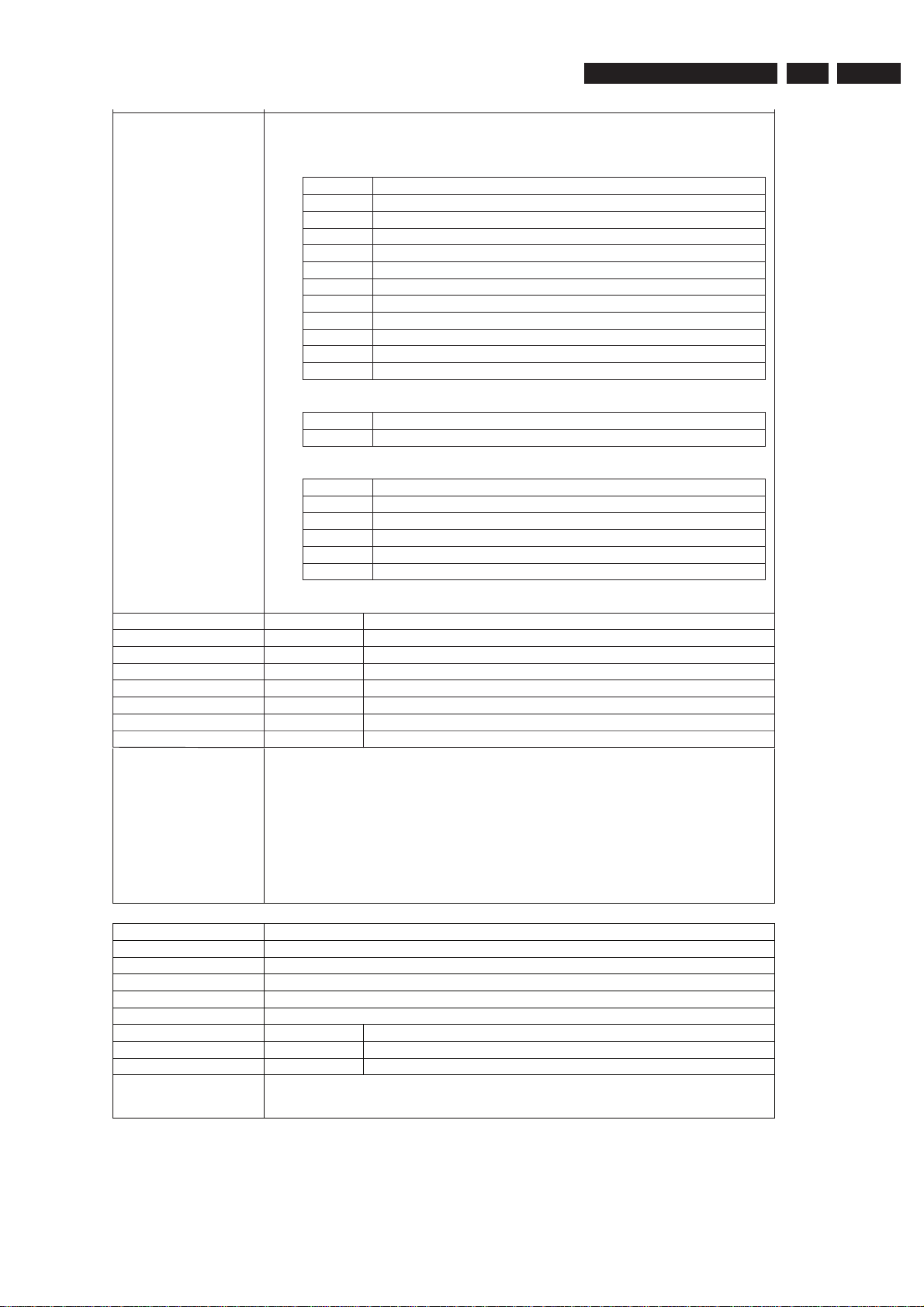
Nucleus Name
DS_CHR_DevTypeGet
Nucleus Number 100
Description Retrieves the device id, the module ids and revisions of the Codec and returns
them to the stdout port.
Technical - Determine the codec id by means of comparing version ids of the modules.
- Read the module-id register of every module and display it to the user.
Execution Time Less than 1 second.
User Input None
Error Number Description
10000 Getting the information succeeded
10001 Wrong codec id detected
Example
DS:> 100
010000:
Device ID 7100
Codec ID PNX7100_C
F-BCU (0x0102) 1.0 INTC (0x011d) 1.0 PCI-XIO(0x0113) 1.0
SIF (0x013b) 1.0 EJTAG (0x0104) 0.1 S-BCU (0x0102) 1.0
BOOT (0x010a) 1.0 CONFIG (0x013f) 1.1 RESET (0x0123) 1.0
DEBUG (0x0116) 0.0 UART0 (0x0107) 0.1 UART1 (0x0107) 0.1
UART2 (0x0107) 0.1 UART3 (0x0107) 0.1 I2C0 (0x0105) 0.1
I2C1 (0x0105) 0.1 GPIO (0x013c) 1.0 SYNC (0x013a) 1.0
DISP0 (0xa015) 1.12 DISP1 (0xa00f) 1.1 OSD (0x0136) 0.1
SPU (0xa00e) 0.0 MIXER (0x0137) 1.0 DENC (0x0138) 1.0
CCIR (0x0139) 1.0 VDEC (0x0133) 0.2 PARSER (0xa00d) 0.0
DV (0xa00c) 0.0 BEI (0xa00a) 0.1 IDE (0xa009) 0.1
SGDX (0xa008) 1.0 BYTE (0xa00b) 0.1 OUTPUT (0xa003) 1.0
ACOMP (0xa000) 1.0 VFE (0xa001) 0.1 VCOMP (0xa002) 1.0
SCR (0x0000) 0.0 SIFF (0xa011) 0.1 WMD (0xa010) 0.0
AUDIO0 (0xa015) 1.12 AUDIO1 (0xa00f) 1.1 PSCAN (0xa018) 0.1
Test OK @
Nucleus Name
DS_CHR_TestImageOn
Nucleus Number 101
Description Generates a test-image of a selected video standard on selected video output
on the digital board. When no input is given, the default values will be used (see
user input description below). Make sure to use the proper nuclei to route the
video signal on the analogue board to get the video signal to the proper output.
Note: Although a DTT has a Chrysalis C3, the codec IC may never use the
YUV functionality of the internal DENC. This is specified by the hardware. The
digital boards for DTT do have a YUV-matrix. The signals from this YUV-matrix
are not routed to the regular video output connector but to the progressive scan
output connector.
Technical - Validate the user input.
- Initialise the SYNC module.
- Initialise the DISPLAY module.
- Initialise the MIXER module.
- Initialise the DENC module.
- Set the selected video standard.
- Generate the selected test image in memory.
- Start the DISPLAY module.
- Start the MIXER module.
- Start the DENC module according to the selected test image id.
Execution Time 6 seconds.
Page 19
Firmware Upgrading & Diagnostic Software
3139 785 31532
User Input The user has to decide which test image, video standard and video output must
be used: < Test image id > < Video standard > < Video output >
Test image id:
0 VERTICAL_COLOURBAR (default)
1 HORIZONTAL_COLOURBAR
2WHITE
3 YELLOW
4 CYAN
5 GREEN
6 MAGENTA
7 RED
8 BLUE
9 BLACK
10 GRAY
11 TEST_IMAGE_FOR_PROGRESSIVE_SCAN
Video standard:
PAL Standard PAL 50 Hz (default)
NTSC Standard NTSC 60 Hz
Video output:
ALL CVBS and YC and RGB DACs are enabled (default)
CVBS CVBS DAC is enabled
YC Y and C DAC is enabled
RGB CVBS, R, G, and B DACs are enabled
YUV Y, U, and V DACs are enabled
PSCAN Progressive scan is enabled.
5.
EN 19
Error Number Description
10100 Generating the test image succeeded.
10101 Invalid input was provided.
10102 The Codec SYNC-module cannot be initialised.
10103 The Codec MIXER-module cannot be initialised.
10104 The Codec VPP-module cannot be initialised.
10105 The Codec DENC-module cannot be initialised.
10106 The digital board hardware information is corrupt
Example
Nucleus Name
DS:> 101
010100:
Test OK @
DS:> 101 0 pal cvbs
010100:
Test OK @
DS:> 101 4 ntsc yc
010100:
Test OK @
DS_CHR_TestImageOff
Nucleus Number 102
Description Switches the test-image off.
Technical - Stop the DENC module.
Execution Time Less than 1 second.
User Input None
Error Number Description
10200 Stopping the test image generation succeeded
10201 The Codec DENC-module failed.
Example
DS:> 102
010200:
Test OK @
Page 20
EN 20
5.
3139 785 31532
Firmware Upgrading & Diagnostic Software
Nucleus Name
DS_CHR_SineOn
Nucleus Number 103
Description Generate an audio sine signal on the audio output of the digital board.
Note: Left channel 6kHz, right channel 12 kHz sine. Make sure to route the
signal first.
Technical - De-mute the analogue board
- Set fifo parameters for audio
- Set the volume
- Set the I2S outputs and configuration paths
- Set the decoder mode
- Configure the audio decoder
- Put the AC3 audio in the fifo
- Send ‘prepare’ command to the audio decoder
- Send ‘play’ command to the audio decoder
Execution Time Less than 1 second
User Input None
Error Number Description
10300 The sine signal was successfully generated
10301 The analogue board could not be de-muted
10302 The audio decoder did not initialise
10303 The dsp2 (DUET) of the audio decoder did not configure
10304 The dsp1 (PALM) of the audio decoder did not configure
10305 There was a delay-error before starting
10306 Wrong input was given to the decoder function
10307 Wrong input was given to the decoder function @@@@@
10308 The audio decoder did not get into the ‘prepared’ state
Example
DS:> 103
010300:
Test OK @
Nucleus Name
DS_CHR_SineOff
Nucleus Number 104
Description Stop generating the audio sine signal
Technical - Reset the audio block of the Codec
Execution Time Less than 1 second.
User Input None
Error Number Description
10400 Switching off the audio sine signal succeeded
10401 Failed to reset the audio decoder
Example
Nucleus Name
DS:> 104
010400:
Test OK @
DS_CHR_SineBurst
Nucleus Number 105
Description Generate an audio sine signal on the audio output of the digital board for 4
seconds.
Note: Left channel 6kHz, right channel 12 kHz sine with some known hick-ups
Technical - Call the DS_CHR_SineOn nucleus
- Delay for 4 seconds
- Call the DS_CHR_SineOff nucleus
Execution Time 4 seconds
User Input None
Error Number Description
10500 The sine signal burst was successfully generated
10501 The delay did not succeed during the burst
10502 The audio sine could not be generated
Example
DS:> 105
010500:
Test OK @
Page 21
Firmware Upgrading & Diagnostic Software
3139 785 31532
5.
EN 21
Nucleus Name
DS_CHR_MuteOn
Nucleus Number 106
Description Mute the audio outputs of the digital bo ard
Technical - Send the ‘Mute’ command to the audio decoder
- Activate the ‘audio mute’ PIO pin
Execution Time Less than 1 second.
User Input “PIO” to just use the PIO pin mute. When muting using this, also de-mute using
this as this works ‘paired’.
Error Number Description
10600 Muting the audio succeeded
10601 Muting the audio through the PIO-pin failed
Example
Nucleus Name
DS:> 106
010600:
Test OK @
DS:> 106 PIO
010600:
Test OK @
DS_CHR_MuteOff
Nucleus Number 107
Description De-mute the audio outputs of the digital board
Technical - Send the ‘DeMute’ command to the audio decoder
- Deactivate the ‘audio mute’ PIO pin
Execution Time “PIO” to just use the PIO pin de-mute. Only de-mute using this when you muted
using the PIO parameter, as this works ‘’paired.
User Input None
Error Number Description
10700 De-muting the audio succeeded
10701 De-muting the audio through the PIO-pin failed
Example
DS:> 107
010700:
Test OK @
DS:> 107 PIO
010700:
Test OK @
Nucleus Name
DS_CHR_DvLedOn
Nucleus Number 108
Description Check the connection to the DV-LED on the digital board by switching it on
Technical - Write to the PIO pin to light the DV LED
Execution Time Less than 1 second.
User Input None
Error Number Description
10800 Switching the DV-LED on succeeded
10801 Switching the DV-LED on failed
Example
Nucleus Name
DS:> 108
010800:
Test OK @
DS_CHR_DvLedOff
Nucleus Number 109
Description Switch off the DV-LED on the digital board
Technical - Write to the PIO pin to switch off the DV LED
Execution Time Less than 1 second.
User Input None
Error Number Description
10900 Switching the DV-LED off succeeded
10901 Switching the DV-LED off failed
Example
DS:> 109
010900:
Test OK @
Page 22

EN 22
5.
3139 785 31532
Firmware Upgrading & Diagnostic Software
Nucleus Name
DS_CHR_MacroVisionOn
Nucleus Number 110
Description Turn on MacroVision.
Technical - Set some registers of the DENC module in the Codec.
Execution Time Less than 1 second.
User Input None
Error Number Description
11000 Turning on MacroVision succeeded
11001 Turning on MacroVision failed
Example
Nucleus Name
DS:> 110
011000:
Test OK @
DS_CHR_MacroVisionOff
Nucleus Number 111
Description Turn off MacroVision.
Technical - Set some registers of the DENC module in the Codec.
Execution Time Less than 1 second.
User Input None
Error Number Description
11100 Turning off MacroVision succeeded
11101 Turning off MacroVision failed
Example
Nucleus Name
DS:> 111
011100:
Test OK @
DS_CHR_Peek
Nucleus Number 112
Description Peek a value on a specified address
Technical - Check the user input
- Read out the address specified
- Check whether the address to be read is aligned on 4 bytes
Execution Time Less than 1 second.
User Input The address to peek on
Error Number Description
11200 Peeking on the specified address succeeded
11201 Peeking on the specified address failed, wrong user input
11202 Peeking on the specified address failed due to misalignment
Example
DS:> 112 0xa0700000
011200: Value read = 0x000001BD
Test OK @
Nucleus Name
DS_CHR_Poke
Nucleus Number 113
Description Poke a value on a specified address
Technical - Check the user input
- Change the value on the address specified
- Check whether the address to be modified is aligned on 4 bytes
Execution Time Less than 1 second.
User Input The address to poke and the value: <address><value>
Error Number Description
11300 Poking the specified address succeeded
11301 Poking the specified address failed, wrong user input
11302 Poking the specified address failed due to misalignment
Example
DS:> 113 0xa0700000 0xaabbccdd
011300:
Test OK @
Page 23
Firmware Upgrading & Diagnostic Software
3139 785 31532
5.
EN 23
Nucleus Name
DS_CHR_INT_PICInterrupts
Nucleus Number 114
Description Test all interrupts of the priority interrupt controller
Technical - Install interrupt handlers
- Generate interrupts
- Test whether all interrupts were received
Execution Time Less than 1 second.
User Input Error Number Description
11400 Testing all the PIC interrupts succeeded
11401 Testing all the PIC interrupts failed
Example
Nucleus Name
DS:> 114
011400:
Test OK @
DS_CHR_DMA_TestDMA
Nucleus Number 115
Description Test the memory to memory DMA transfer
Technical - Create a block with known data in memory
- Copy this block to the consecutive area using 3 different DMAs
- Check whether all DMAs transferred the data properly
Execution Time Less than 2 seconds.
User Input Error Number Description
11500 The testing of the DMAs succeeded
11501 The initialisation of the DMAs failed for one or more DMA
11502 One or more DMAs failed the test
Example
DS:> 115
011500:
Test OK @
Boot EEPROM (BROM)
Nucleus Name
DS_BROM_Communication
Nucleus Number 200
Description Check the communication between the IIC controller of the Codec and the boot
EEPROM
Technical - Initialise IIC
- Read something from the EEPROM
Execution Time Less than 1 second.
User Input None
Error Number Description
20000 The data is properly read so the commu nication is OK
20001 The IIC bus was not accessible
20002 There was a timeout reading the device
20003 The IIC acknowledge was not received
20004 An IIC-bus error occurred
20005 The IIC bus initialisation failed
20006 An unexpected IIC error occurred
Example
DS:> 200
020000:
Test OK @
Page 24
EN 24
5.
3139 785 31532
Firmware Upgrading & Diagnostic Software
Nucleus Name
DS_BROM_WriteRead
Nucleus Number 201
Description Check whether the Boot EEPROM can be written to and read from
Technical - Initialise IIC
- Write something to the EEPROM
- Read from the same location and check whether it is the same as written
Execution Time Less than 1 second.
User Input None
Error Number Description
20100 The write-read test succeeded
20101 The write-read test failed
20102 An IIC-bus error occurred
20103 There was a timeout reading the device
20104 The IIC bus was not accessible
20105 The IIC acknowledge was not received
20106 Got unknown IIC bus error
20107 The IIC bus initialisation failed
Example
Non Volatile RAM (NVRAM)
Nucleus Name
DS:> 201
020100:
Test OK @
DS_NVRAM_Communication
Nucleus Number 300
Description Check the communication between the IIC controller of the Codec and the
NVRAM EEPROM
Technical - Initialise IIC
- Read from a location in the NVRAM EEPROM device
Important note:
This nucleus only checks the physical connection between the Codec and IIC
EEPROM. If no EEPROM is mounted this test will fail. However other NVRAM
nuclei might still work because the software will store NVM data into flash
memory
Execution Time Less than 1 second.
User Input None
Error Number Description
30000 Something is properly read so the communication is OK
30001 The IIC bus was not accessible
30002 There was a timeout reading the device
30003 The IIC acknowledge was not received
30004 The communication with the device failed
30005 The IIC bus initialisation failed
Example
DS:> 300
030000:
Test OK @
Nucleus Name
DS_NVRAM_WriteRead
Nucleus Number 301
Description Check whether the EEPROM can be written to and read from
Technical - Initialise IIC
- If no IIC EEPROM was found then initialise flash memory to use NVM
pages
- Backup data from location to modify
- Write to location and read it back again
- Write back the backed up data to the location to leave the NVRAM as
found
Execution Time Less than 1 second
User Input None
Error Number Description
30100 The write-read test succeeded
30101 The IIC bus could not be initia lised
30102 There was an NVRAM IO error
30103 The value could not be read back from the NVRAM
Example
DS:> 301
030100:
Test OK @
Page 25
Firmware Upgrading & Diagnostic Software
3139 785 31532
5.
EN 25
Nucleus Name
DS_NVRAM_Clear
Nucleus Number 302
Description Make the EEPROM empty, containing all zeroes.
Technical - Initialise IIC
- If no IIC EEPROM was found then initialise flash memory to use NVM
pages
- Read the DVID and diversity string from NVM (either EEPROM or Flash)
- Create a memory block filled with zeroes
- Write this block to the NVRAM (either EEPROM or Flash)
- Write back the Read the DVID and diversity string to NVM (either
EEPROM or Flash)
Important note:
The Hardware Diversity Information and unique identification number
(IEE1394-specific) of the Digital Video processing part is NOT cleared by this
nucleus!
Execution Time 16 seconds
User Input None
Error Number Description
30200 The clearing of the NVRAM succeeded
30201 There was an IIC error
30202 Clearing the NVRAM failed
Example
Nucleus Name
DS:> 302
030200:
Test OK @
DS_NVRAM_Modify
Nucleus Number 303
Description Modifies one or more locations in NVRAM and updates the checksum of the
section modified
Technical - Initialise IIC
- If no IIC EEPROM was found then initialise flash memory to use NVM
pages
- Decode user input
- Modify the NVRAM as indicated
- Validate the NVRAM by calculating the checksum and stor ing it
Execution Time Less than 1 second
User Input 1. The location that must be modified
i.e. "ALL" "BOOT" "DIAGNOSTICS" "DOWNLOAD" "CONFIG"
"RECORDER" or no string if an offset from the base address of the
NVRAM is required
2. The offset and data which to put on the selected loc ation
<offset> <length> <data>
Error Number Description
30300 Modifying the NVRAM contents succeeded
30301 Unable to initialise NVM
30302 Modifying the NVRAM contents failed
30303 length out of range
30304 unable to decode length
30305 offset out of range
30306 unable to decode offset
30307 unknown location specifie d
30308 no location is specified
30309 number of values incorrect
30310 There was an IIC error
Example
DS:> 303 DIAGNOSTICS 5 1 0x5a
030300: Section is modified successfully
Test OK @
Page 26

EN 26
5.
3139 785 31532
Firmware Upgrading & Diagnostic Software
Nucleus Name
DS_NVRAM_Read
Nucleus Number 304
Description Read out one or more locations in the NVRAM
Technical - Initialise IIC
- If no IIC EEPROM was found then initialise flash memory to use NVM
pages
- Decode user input
- Read from the NVRAM and return this info to the user
Execution Time Less than 1 second
User Input 1. The location which must be read
i.e. "ALL" "BOOT" "DIAGNOSTICS" "DOWNLOAD" "CONFIG"
"RECORDER" or no string if an offset from the base address of the
NVRAM is required
2. The offset and number of bytes to read
<offset> <length>
Error Number Description
30400 Value read
30401 Unable to initialise NVM
30402 Reading the NVRAM contents failed
30403 Length out of range
30404 Unable to decode length
30405 Offset out of range
30406 Unable to decode offset
30407 Unknown location specified
30408 No location is specified
Example
304 DIAGNOSTICS 0 6
030400: Value read = 0x00 0x00 0x00 0x00 0x00 0x5A
Test OK @
SDRAM (SDRAM)
Nucleus Name
DS_SDRAM_WriteRead
Nucleus Number 400
Description Check all data lines, address lines and memory locations of the SDRAM
Technical - Test the data bus
- Test the address bus
- Test the integrity of the device itself (memory locations)
Execution Time 11 seconds for 32 Mb
23 seconds for 64 Mb
User Input None
Error Number Description
40000 The write-read test succeeded
40001 The data bus contains an error
40002 The address bus contains an error
40003 The SDRAM itself contains an error
Example
Nucleus Name
DS:> 400
040000:
Test OK @
DS_SDRAM_WriteReadFast
Nucleus Number 401
Description Check all data lines and address lines of the SDRAM
Technical - Test the data bus
- Test the address bus
Execution Time Less than 1 second
User Input None
Error Number Description
40100 The write-read test succeeded
40101 The data bus contains an error
40102 The address bus contains an error
Example
DS:> 401
040100:
Test OK @
Page 27
Firmware Upgrading & Diagnostic Software
3139 785 31532
5.
EN 27
Nucleus Name
DS_SDRAM_Write
Nucleus Number 402
Description Write to a specific un-cached memory address
Technical - Decode the user input and check its ranges and a lignment on 4 bytes
- Write the data to the SDRAM
Execution Time Less than 1 second
User Input 1. The location that must be modified
(SDRAM starts at address 0xA0000000)
2. The value to put on the selected location
Error Number Description
40200 Writing to the SDRAM succeeded
40201 Writing to the SDRAM failed; Wrong user input
40202 Address is not dividable by 4
Example
Nucleus Name
DS:> 402 0xa1000010 0xad112222
040200:
Test OK @
DS_SDRAM_Read
Nucleus Number 403
Description Read from a specific un-cached memory address
Technical - Decode the user input and check the ranges
- Read from the SDRAM and return this info to the user
Execution Time Less than 1 second
User Input The location from which the data must be read
(SDRAM starts at address 0xA0000000)
Error Number Description
40300 Reading from the SDRAM succeeded
40301 Reading from the SDRAM failed; Wrong user input
40302 Address is not dividable by 4
Example
DS:> 403 0xa1000010
040300: Value read = 0xAD112222
Test OK @
Nucleus Name
DS_SDRAM_DmaWriteRead
Nucleus Number 404
Description Write a pattern to the entire SDRAM using DMA and check the data
Technical - Check if the Stack pointer is not in the write range
- Clear a 64kb block and then fill it with a pattern
- Initialise the DMA controller and write the data to the SDRAM
- Then check if all the data was written correctly (except descriptor tables)
- Repeat the process 4 times with 4 different patterns
Execution Time 24 seconds
User Input None.
Error Number Description
40400 Writing to the SDRAM succeeded
40401 Stack area definition ERROR!
40402 DMA controller could not be initialised.
40403 Not all data was transferred correctly
Example
DS:> 404
040400:
Test OK @
Page 28

EN 28
FLASH (FLASH)
5.
3139 785 31532
Firmware Upgrading & Diagnostic Software
Nucleus Name
DS_FLASH_DevTypeGet
Nucleus Number 500
Description Get the device (revision) type information of the FLASH ICs. (type,
manufacturer, device ID and size)
Technical - Set the timing for the flash writing
- Write a command sequence to determine device type information
- Return the information to the user
Execution Time Less than 1 second
User Input None
Error Number Description
50000 Getting the information from the FLASH succeeded
50001 Getting the information from the FLASH failed
Example
Nucleus Name
DS:> 500
050000: Found FLASH memory:
NOR AMD 29DL640G 8MB,NOR AMD 29DL640G 8MB
Test OK @
DS_FLASH_WriteRead
Nucleus Number 501
Description Check whether the FLASH can be written to and read from
Technical - Find the test segment in flash
- Read the data into SDRAM
- Modify the data
- Write this data from SDRAM to FLASH and verify it by reading back again
Execution Time Less than 1 second.
User Input None
Error Number Description
50100 The FLASH write-read test succeed ed
50101 The test segment could not be found
50102 All bits in the TEST region are filled with 0 (region exhausted)
50103 The Write Read test failed
50104 The Write Failed
Example
DS:> 501
050100:
Test OK @
Nucleus Name
DS_FLASH_Read
Nucleus Number 502
Description Read from a specific memory address in FLASH
Technical - Decode the user input and check the ranges and whether the address is
aligned on 4 bytes
- Read the data and return this to the user
Execution Time Less than 1 second.
User Input The location from which data must be read
(FLASH starts at address 0xB8000000)
Error Number Description
50200 Reading the FLASH succeeded
50201 Reading the FLASH failed; Wrong user input
50202 Address is not dividable by 4
Example
DS:> 502 0xb8000000
050200: Value read = 0x3C08A000
Test OK @
Page 29
Firmware Upgrading & Diagnostic Software
3139 785 31532
5.
EN 29
Nucleus Name
DS_FLASH_ChecksumProgram
Nucleus Number 503
Description Check the checksum of the application partitions by recalculating and
comparing partition checksums
Technical - Determine the number of segments
- Find the application in each segment and determine its checksum
- Check whether the checksums stored match the newly calculated
Execution Time 6 seconds
User Input None
Error Number Description
50300 The checksum is valid, the test succeeded
50301 The checksum is invalid
Example
Nucleus Name
DS:> 503
050300:
BootCode checksum is: 0xBABE5B6F, which is correct
Diagnostics checksum is: 0xBABEBAFF, which is correct
Download checksum is: 0xBABEEDBF, which is correct
Application checksum is: 0xBABE8EEC, which is correct
Test OK @
DS_FLASH_CalculateChecksum
Nucleus Number 504
Description Calculate the checksum over all memory addresses. Used to check entire
FLASH contents
Technical - Run the checksum calculation algorithm on all flash memory addresses
Execution Time 6 seconds
User Input None
Error Number Description
50400 Calculating the checksum over all addresses succeeded
Example
DS:> 504
050400: The Checksum = 0xBABE30A4
Test OK @
Nucleus Name
DS_FLASH_CalculateChecksumFast
Nucleus Number 505
Description Calculate a checksum over a selected number of address locations
Technical - Run the checksum calculation algorithm on a selected number of flash
memory addresses
Execution Time 6 seconds
User Input None
Error Number Description
50500 Calculating the checksum over selected addresses succeeded
Example
Video Input Processor (VIP)
Nucleus Name
DS:> 505
050500: The Checksum = 0xBABEB064
Test OK @
DS_VIP_DevTypeGet
Nucleus Number 600
Description Get the device (revision) type information of the VIP IC
Technical - Initialise IIC
- Read out the device (revision) type information of the VIP IC
Execution Time Less than 1 second
User Input None
Error Number Description
60000 Getting the information from the VIP succeeded
60001 The IIC bus initialisation failed
60002 The was an error getting the information from the VIP
60003 Type not according to t ype stored in HW diversity string
Example
DS:> 600
060000: Found SAA7118
Test OK @
Page 30

EN 30
5.
3139 785 31532
Firmware Upgrading & Diagnostic Software
Nucleus Name
DS_VIP_Communication
Nucleus Number 601
Description Check the communication between the IIC controller of the Codec and the VIP
IC
Technical - Initialise IIC
- Read data from a location in the VIP
Execution Time Less than 1 second
User Input None
Error Number Description
60100 Communicating with the VIP succeeded
60101 The IIC bus was not accessible
60102 There was a timeout reading the device
60103 The IIC acknowledge was not received
60104 The communication with the device failed
60105 The IIC bus initialisation failed
Example
Nucleus Name
DS:> 601
060100:
Test OK @
DS_VIP_ClockOutputOn
Nucleus Number 602
Description Switch the clock output on
Technical - Initialise IIC
- Set the clock output through IIC
Execution Time Less than 1 second
User Input None
Error Number Description
60200 Switching the clock output on succeeded
60201 Switching the clock output on faile d
Example
DS:> 602
060200:
Test OK @
Nucleus Name
DS_VIP_ClockOutputOff
Nucleus Number 603
Description Switch the clock output off
Technical - Initialise IIC
- Reset the clock output through IIC
Execution Time Less than 1 second
User Input None
Error Number Description
60300 Switching the clock output off succeeded
60301 Switching the clock output off failed
Example
DS:> 603
060300:
Test OK @
Page 31

Firmware Upgrading & Diagnostic Software
3139 785 31532
5.
EN 31
Nucleus Name
Nucleus Number 604
Description Select an input video path to be switched to the analogue output pin (AOUT) of
Technical - Check the user input
Execution Time Less than 1 second
User Input The input to select, see table below.
DS_VIP_SelectInput
the VIP
- Initialise IIC
- Read out the VIP id
- Write the set of registers required for the input specified
Available channels for input of the 7118 and their description:
Channel number Description
1 CVBS_Y_IN_A
2 CVBS_OUT_B
3 CVBS_Y_IN_B
4 CVBS_Y_IN_C
6 C_IN
8 G_IN
9 Y_IN
13 B_IN
14 U_IN
18 R_IN
19 V_IN
Available channels for input of the 7115 and their description:
Channel number Description
1 CVBS_Y_IN_B
2 CVBS_OUT_B_VIP
4 C_IN_VIP
7 CVBS_Y_IN_B
Available channels for input of the 7119 and their description:
Channel number Description
1 Y / CVBS
3 CVBS
4 Y3
6 C / CVBS
8 G
9 Y
12 Y2
13 B
14 U
17 C
18 R
19 V
Available channels for input of the 7173 and their description:
Channel number Description
1 CVBS_TUNER_IN
2 CVBS_REAR_IN
3 CVBS_FRONT_IN
4 C_REAR_IN
5 Y_REAR_IN
6 Y_FRONT_IN
7 C_FRONT_IN
8 AL_REAR_IN
9 AL_FRONT_IN
10 AR_FRONT_IN
11 AR_REAR_IN
12 SIF_TUNER_IN
Page 32

EN 32
5.
3139 785 31532
Firmware Upgrading & Diagnostic Software
Error Number Description
60400 Selecting the input of the VIP succeeded
60401 The user provided wrong input
60402 The VIP was not accessible
60403 An unsupported VIP was found
Example
Digital Video Input Output Circuit (DVIO)
DS:> 604 1
060400:
Test OK @
Nucleus Name
DS_DVIO_LinkDevTypeGet
Nucleus Number 700
Description Get the device (revision) type information of the 1394 Link layer IC
Technical - Initialise the PIO pins on the Codec
- Read out the ID register
Execution Time Less than 1 second
User Input None
Error Number Description
70000 Getting the information from the link layer IC succeeded
70001 Getting the information from the link layer IC failed
70002 Type not according to t ype stored in HW diversity string
Example
Nucleus Name
DS:> 700
070000: Device type of the link layer IC: ffc00301
Test OK @
DS_DVIO_PhyDevTypeGet
Nucleus Number 701
Description Get the device (revision) type information of the 1394 Physical la yer IC
Technical - Initialise the PIO pins of the Codec
- Write the PHY-access register in the Link chip to indicate phy read access
- Wait until the link chip has obtained the value from the phy-chip
- Read this out and filter the data to be returned to the user
Execution Time Less than 1 second
User Input None
Error Number Description
70100 Getting the information from the physical layer IC succeeded
70101 The physical layer IC was not accessible
70102 Getting the information from the physical layer IC failed
70103 Type not according to t ype stored in HW diversity
Example
DS:> 701
070100: Physical layer IC: VendorID: 0x006037, ProductID: 0x412801
Test OK @
Nucleus Name
DS_DVIO_LinkCommunication
Nucleus Number 702
Description Check the accessibility of the 1394 Link layer IC by writing to and reading from
a specific address
Technical - Initialise the PIO pins of the Codec
- Write a pattern to the CYCTM register of the link chip
- Read back and verify the pattern
Execution Time Less than 1 second
User Input None
Error Number Description
70200 Communicating with the link la yer IC succeeded
70201 Communicating with the link la yer IC failed
70202 Result of nucleus not according to HW diversity string
Example
DS:> 702
070200:
Test OK @
Page 33

Firmware Upgrading & Diagnostic Software
3139 785 31532
5.
EN 33
Nucleus Name
DS_DVIO_PhyCommunication
Nucleus Number 703
Description Check the acc essibility of the 1394 Physical layer IC by writing to and reading
from a specific address
Technical - Initialise the PIO pins of the Codec
- Initialise IIC
- Write the data to be written to the PHY-chip to the link chip first
- Wait until the link chip indicates that the data has been written to the PHY
- Write the PHY-access register in the Link chip to indicate PHY read access
- Wait until the link chip has obtained the value from the PHY-chip
- Test whether the value read back equals the one previousl y written
Execution Time Less than 1 second
User Input None
Error Number Description
70300 Communicating with the ph ysical layer IC succeeded
70301 The physical layer IC was not accessible
70302 Communicating with the physical layer IC failed
70303 Result of nucleus not according to HW diversity string
Example
Nucleus Name
DS:> 703
070300:
Test OK @
DS_DVIO_Routing
Nucleus Number 704
Description Route a DV stream contain ing an audio and video signal through the physical
and link layer ICs to the Codec. This test works for both NTSC and PAL.
Technical - Initialise the DMA to transfer 5 frames PAL/NTSC
- Initialise the DV de-multiplexer
- Initialise the 1394 interface and start reception of the DV stream
- Check whether the stream was copied to memory properly by the byte
input interface (port to memory type DMA)
Execution Time 6-10 seconds (6 when OK, 10 when no stream or error)
User Input None
Error Number Description
70400 Routing the signals succ eeded
70401 The 1394 link chip could not be initialised properly
70402 There was a syntax error in the DV stream
70403 DMA could not copy DV stream to memory. Stream connected?
70404 DMA not working properly
Example
DS:> 704
070400:
Test OK @
Nucleus Name
DS_DVIO_DetectNode
Nucleus Number 705
Description Check whether a DV node can be d etected b y the har d ware. T his test works for
both NTSC and PAL.
Technical - Initialise the 1394 interface
- Detect whether a node is in range
Execution Time 3 or 5 seconds (3 when OK, 5 when no stream or error)
User Input None
Error Number Description
70500 The node was detected OK
70501 The 1394 link chip could not be initialised properly
70502 Unable to write to 1394 PHY chip
70503 Unable to read from 1394 PHY chip
70504 No node was detected
Example
DS:> 705
070500:
Test OK @
Page 34

EN 34
5.
3139 785 31532
Firmware Upgrading & Diagnostic Software
Nucleus Name
DS_DVIO_DetectStream
Nucleus Number 706
Description Check whether a DV stream can be detected by the hardware. T his test works
for both NTSC and PAL.
Technical - Initialise the 1394 interface
- Start receiving the stream
- Detect whether the stream is OK
Execution Time 3 or 5 seconds (3 when OK, 5 when no stream or error)
User Input None
Error Number Description
70600 The stream was detected
70601 The 1394 link chip could not be initialised properly
70602 No stream detected
Example
Progressive Scan Circuit (PSCAN)
Nucleus Name
DS:> 706
070600:
Test OK @
DS_PSCAN_DevTypeGet
Nucleus Number 800
Description Get the device (revision) type information of the progressive scan ic.
Technical - Initialise the progressive scan ic.
- Try to read the version register of the progressive scan ic.
Execution Time 1 second
User Input None
Error Number Description
80000 Everything went well.
80001 The communication with the device failed
80002 No chip was expected
Example
DS:> 800
080000:
Chip name : 2300
Chip version : 1
Test OK @
DS:> 800
080000:
Chip name : ADV7196
Test OK @
DS:> 800
080000:
Chip name : ADV7302
Test OK @
Nucleus Name
DS_PSCAN_Communication
Nucleus Number 801
Description Check the communication between the IIC controller of the Codec and the
progressive scan IC
Technical - Initialise IIC
- Write data to a register of the progressive scan ic through IIC
Execution Time Less than 1 second
User Input None
Error Number Description
80100 Communicating with the progressive sca n ic succeeded
80101 The IIC bus was not accessible
80102 There was a timeout reading the device
80103 The IIC acknowledge was not received
80104 Communicating with the progressive sca n ic failed
80105 The initialisation of the IIC bus failed
80106 The read data is not the same as the written data
80107 No chip was expected
Example
DS:> 801
080100:
Test OK @
Page 35

Firmware Upgrading & Diagnostic Software
3139 785 31532
5.
EN 35
Nucleus Name
DS_PSCAN_TestImageOn
Nucleus Number 802
Description Generate the test images that are present on the progressive scan IC.
Technical - Determine whether the user wanted a HATCH or a FRAME image pattern
- Initialise the PIO pins of the Codec
- Initialise IIC
- Reset the DENC
- Enable the 27Mhz clock
- Send all settings for the pattern to the DENC through IIC
Execution Time Less than 1 second
User Input In case of ADV7196:
When no input is given “HATCH” is the default
-“HATCH”
-“FRAME”
Remark:
“HATCH” is a crosshatch test pattern (horizontal and vertical white lines are
displayed against a black background)
“FRAME” is a uniform coloured frame/field test pattern (default white).
In case of FLI2300: Nothing.
Error Number Description
80200 The generation of the test image succeeded
80201 Unable to initialise PSCAN IC
80202 Unable to reset DENC
80203 Unable to generate image
80204 No chip was expected
Example
DS:> 802 HATCH
080200:
Test OK @
Nucleus Name
DS_PSCAN_TestImageOff
Nucleus Number 803
Description Switch off the generated test image
Technical - Initialise IIC
- Send the default DENC settings to the DENC through IIC
Execution Time Less than 1 second
User Input None
Error Number Description
80300 Turning off the test image succeed ed
80301 Unable to initialise PSCAN IC
80302 IIC Error during writing PSCAN IC
80303 No chip was expected
Example
DS:> 803
080300:
Test OK @
Page 36

EN 36
5.
3139 785 31532
Firmware Upgrading & Diagnostic Software
Nucleus Name
DS_PSCAN_TestImageColourSettingsSet
Nucleus Number 804
Description Set the colour of the hatch- or the frame- field to a different value than the
default white
Technical - Determine which colour must be set.
- Initialise IIC.
- Enable 27 MHz PSCAN Clock.
- Send all settings to the DENC through IIC.
Execution Time Less than 1 second.
User Input A colour string of one of the next non-case sensitive strings ( WHITE, BLACK,
RED, GREEN, BLUE, YELLOW, CYAN, MAGENTA ) or Y Cr Cb (hexa-)
decimal values.
Error Number Description
80400 Setting the new colour-settings succeeded
80401 The user provided wrong input
80402 Unable to initialise PSCAN IC
80403 Unable to set colour
80404 No chip was expected
Example
Nucleus Name
DS:> 804 yellow
080400:
Test OK @
DS:> 804 0x6a 0xde 0xca
080400:
Test OK @
DS_PSCAN_TestImageColourSettingsGet
Nucleus Number 805
Description Get the colour settings of the hatch- or the frame- field.
Technical - Initialise IIC.
- Read the colour settings from the DENC through IIC.
Execution Time Less than 1 second.
User Input None
Error Number Description
80500 Getting the colour-settings succeeded
80501 The progressive scan DENC-IC was not accessible through IIC
80502 Unable to get colour
80503 No chip was expected
Example
DS:> 805
080500: Colour Y Cr Cb values: 0xD2 0x92 0x10
Test OK @
Nucleus Name
DS_PSCAN_Routing
Nucleus Number 806
Description Route a video signal from the codec host processor through the progressive
scan ICs to the progressive scan output of the set.
Note: To route the progressive scan to the output of the set, first call the
nucleus to do the video routing on the analogue (part of the) board.
Technical - Initialise the PIO pins of the codec
- Initialise IIC
- Reset the DENC
- Enable the 27Mhz clock
- Send all settings to the DENC through IIC.
Execution Time Less than 1 second.
User Input None
Error Number Description
80600 Routing path is created successfully.
80601 Unable to initialise the Codec.
80602 Unable to access DENC
80603 Unable to access de-interlacer.
80604 Wrong chips were expected.
Example
DS:> 806
080600:
Test OK @
Page 37

Firmware Upgrading & Diagnostic Software
3139 785 31532
5.
EN 37
Nucleus Name
DS_PSCAN_DevTypeGetDeinterlacer
Nucleus Number 807
Description See nucleus 800.
Example
Nucleus Name
DS:> 807
080700:
Chip name : 2300
Chip version : 1
Test OK @
DS_PSCAN_CommunicationDeinterlacer
Nucleus Number 808
Description See nucleus 801.
Example
Basic Engine (BE)
Nucleus Name
DS:> 808
080800:
Test OK @
DS_BE_CommunicationEcho
Nucleus Number 900
Description Check the communication between the digital board and the basic engine by
issuing an echo command
Technical - Check if an AV2 or AV3 is connected
- In case of an AV2 Check the communication bet ween the digital board and
the basic engine by issuing an echo command over the S2B interface
- Check if the BE returned the string 0x00 0xAA 0x55
- In case of an AV3 send an ATAPI TEST_UNIT_READY command
Execution Time Less than 1 second
User Input None
Error Number Description
90000 Communicating with the BE over the S2B interface succeeded
90001 There was a time-out while communic ating
90002 The Basic Engine returned an unexpected result
90003 The Basic Engine returned an error code
90004 No acknowledge received from BE
90005 Communicating with the Basic Engine failed
90006 Echo check failed, no echo re ceived
90007 Echo check failed, received wrong pattern
Example
DS:> 900
090000:
Test OK @
Nucleus Name
DS_BE_Reset
Nucleus Number 901
Description Reset the basic engine
Technical - Check if an AV2 or AV3 is connected
- In case of an AV2 Toggle the reset pin of the I2S interface
- In case of an AV3 Toggle the reset pin of the IDE interface
Execution Time 2 seconds on AV2
9 seconds on AV3 (when disc inside)
User Input None
Error Number Description
90100 Resetting the Basic Engine succeeded
90101 Resetting the Basic Engine failed
Example
DS:> 901
090100:
Test OK @
Page 38

EN 38
5.
3139 785 31532
Firmware Upgrading & Diagnostic Software
Nucleus Name
DS_BE_GetSelftestResult
Nucleus Number 902
Description Return the self-test results through the service port
Technical - Check if an AV2 or AV3 is connected
- In case of an AV2 Send the S2B GET_SELF_TEST_RESULT command
- In case of an AV3 Send the ATAPI REPORT_DRIVE_DIAGNOSTICS
command
- On error display the specific error codes received from the BE
Execution Time Less than 1 second
User Input None
Error Number Description
90200 Self test succeeded, no errors
90201 There was a time-out while communicating
90202 The Basic Engine returned an unexpected result
90203 The BE returned an error code
90204 No acknowledge received from BE
90205 Communicating with the Basic Engine failed
90206 Basic Engine returned no info
90207 Self test failed, errors are echoed
Example
Nucleus Name
DS:> 902
090200:
Self-test result byte : 00000000
Self-test result byte : 00000000
Self-test result byte : 00000000
Test OK @
DS_BE_VersionGet
Nucleus Number 903
Description Get the version of the basic engine and that of the optical unit
Technical - Check if an AV2 or AV3 is connected
- In case of an AV2 send the S2B GET_VERSION_NUMBER command
- In case of an AV3 send the ATAPI INQUIRY command
- Send the GET_OPU_VERSION command
- Display the returned version information
Execution Time Less than 1 second
User Input None
Error Number Description
90300 BE version OK
90301 There was a time-out while communicating
90302 The Basic Engine returned an unexpected result
90303 The BE returned an error code
90304 No acknowledge received from BE
90305 Communicating with the Basic Engine failed
90306 The BE returned no info
Example (AV2)
Example (AV3)
DS:> 903
090300: BE version = 20.09.18 Optical unit version = 3C.00.09.41.08
Test OK @
DS:> 903
090300:
BE version = 31.30.24. PHILIPS ,VAD8031
,31302400,REL_8031_313024 2073,
Optical unit version = 00.06.82.19.00
Test OK @
Page 39

Firmware Upgrading & Diagnostic Software
3139 785 31532
5.
EN 39
Nucleus Name
DS_BE_TrayOut
Nucleus Number 904
Description Open the tray of the basic engine
Technical - Check if an AV2 or AV3 is connected
- In case of an AV2 Send the S2B TRAY_OUT command
- In case of an AV3 send an ATAPI START_STOP_UNIT command
Execution Time Approximately 2 seconds
User Input None
Error Number Description
90400 The command executed successfully
90401 There was a time-out while communicating
90402 The Basic Engine returned an unexpected result
90403 The BE returned an error code
90404 No acknowledge received from BE
90405 Unable to enter normal mode
90406 Communicating with the Basic Engine failed
Example
Nucleus Name
DS:> 904
090400:
Test OK @
DS_BE_TrayIn
Nucleus Number 905
Description Close the tray of the basic engine
Technical - Check if an AV2 or AV3 is connected
- Send the S2B TRAY_IN command
- In case of an AV3 send an ATAPI START_STOP_UNIT command
Execution Time Approximately 1 - 2 seconds
User Input None
Error Number Description
90500 The command executed successfully
90501 There was a time-out while communicating
90502 The Basic Engine returned an unexpected result
90503 The BE returned an error code
90504 No acknowledge received from BE
90505 Unable to enter normal mode
90506 Communicating with the Basic Engine failed
Example
DS:> 905
090500:
Test OK @
Page 40

EN 40
5.
3139 785 31532
Firmware Upgrading & Diagnostic Software
Nucleus Name
Nucleus Number 906
Description Write data to and read data from a DVD+RW disc through the basic engine for
Technical - Check if an AV2 or AV3 is connected
Execution Time Approximately 20 seconds
User Input None
Error Number Description
90600 The command executed successfully
90601 This nucleus cannot be executed because the Self-Test failed
90602 The BE cannot enter normal operating mode
90603 Unable to send the tray in
90604 Unable to read TOC from disc
90605 Invalid disc is loaded, please i nsert a DVD+R W disc
90606 Writing the test pattern to DVD+RW failed
90607 Reading back the test pattern from DVD+RW failed
90608 Compare check failed
90609 Calibrating DVD+RW failed
Example
DS_BE_WriteReadDvdRw
verification of the writing
- Execute DS_BE_GetSelftestResults
- Send the TRAY_IN command
- Send the READ_TOC command
- Generate a random disc location
- Generate test data to write to the DVD+RW
- In case of an AV2 Transfer the test data to the disc location using DMA
- In case of an AV3 Transfer the test data to the disc location using PIO
mode ATAPI WRITE_10
- In case of an AV2 Read back the data from disc using DMA
- In case of an AV3 Transfer the test data to the disc location using PIO
mode ATAPI READ_10
- Compare the two data areas and check whether the areas are equal
DS:> 906
090600: Testing on sector 0x5dbe0: OK
Test OK @
Page 41

Firmware Upgrading & Diagnostic Software
3139 785 31532
5.
EN 41
Nucleus Name
Nucleus Number 907
Description Write data to and read data from a DVD+R disc through the basic engine for
Technical - Check if an AV2 or AV3 is connected
Execution Time Approximately 20 seconds
User Input None
Error Number Description
90700 The command executed successfully
90701 This nucleus cannot be executed because the Self-Test failed
90702 The BE cannot enter normal operating mode
90703 Unable to send the tray in
90704 Unable to read TOC from disc
90705 Invalid disc is loaded, please i nsert a DVD+R W disc
90706 Unable to write, the DVD+R disc is full
90707 No writable DVD+R sector found
90708 Writing the test pattern to DVD failed
90709 Reading back the test pattern from DVD failed
90710 Compare check failed
Example
DS_BE_WriteReadDvdR
verification of the writing
- Execute DS_BE_GetSelftestResults
- Send the TRAY_IN command
- Send the READ_TOC command
- Use the OPC area to test if the DVD+R is (still) writable
- Generate test data to write to the DVD+R
- In case of an AV2 Transfer the test data to the disc location using DMA
- In case of an AV3 Transfer the test data to the disc location using PIO
mode ATAPI WRITE_10
- In case of an AV2 Read back the data from disc using DMA
- In case of an AV3 Transfer the test data to the disc location using PIO
mode ATAPI READ_10
- Compare the two data areas and check whether the areas are equal
DS:> 907
090700: Testing on sector 0x36210: OK
Test OK @
Page 42

EN 42
5.
3139 785 31532
Firmware Upgrading & Diagnostic Software
Note:
Not for ATAPI based drives!
Command may not work for ATAPI based drives!
Nucleus Name
DS_BE_StatisticalInformationGet
Nucleus Number 908
Description Retrieve the statistical information from the basic engine
Technical - Check if an AV2 or AV3 is connected
- In case of an AV2 Send the S2B GET_STATISTICAL_INFO command
- In case of an AV3 Send the transparent BIT engine
GET_STATISTICAL_INFO command
- Display the info returned from the BE
Execution Time Less than 1 second on AV2
2 seconds on AV3
User Input None
Error Number Description
90800 The command executed successfully
90801 There was a time-out while communicating
90802 The Basic Engine returned an unexpected result
90803 The BE returned an error code
90804 No acknowledge received from BE
90805 Communicating with the Basic Engine failed
90806 The BE returned no info
Example (AV2)
Example (AV3)
DS:> 908
Number of times Tray went Open/Closed : 4
Total minutes the CD laser was on : 0
Total minutes the DVD laser was on : 0
Total minutes the write laser was on : 0
090800:
Test OK @
DS:> 908
Number of times Tray went Open/Closed
4
Total time the power power on (HR:MIN)
0:0h
Total time of reading CDROM discs (HR:MIN)
0:0h
Total time of reading high speed CD-R discs (HR:MIN) 0:0h
Total time of reading other CD-R discs (HR:MIN) 0:0h
Total time of reading high speed CD-RW discs (HR:MIN) 0:0h
Total time of reading other CD-RW discs (HR:MIN) 0:0h
Total time of reading high speed DVD SL discs (HR:MIN) 0:0h
Total time of reading other DVD SL discs (HR:MIN) 0:0h
Total time of reading high speed DVD DL discs (HR:MIN) 0:0h
Total time of reading other DVD DL discs (HR:MIN) 0:0h
Total time of reading high speed DVD+R discs (HR:MIN) 0:0h
Total time of reading other DVD+R discs (HR:MIN) 0:2h
Total time of reading high speed DVD+RW discs (HR:MIN) 0:0h
Total time of reading other DVD+RW discs (HR:MIN) 0:35h
Total time of writing DVD+R discs at 2.4 x (HR:MIN) 0:0h
Total time of writing DVD+R discs at 4 x (HR:MIN) 0:0h
Total time of writing DVD+RW discs at 2.4 x (HR:MIN) 0:0h
Total time of writing DVD+RW discs at 4 x (HR:MIN) 0:0h
090800:
Test OK @
Page 43

Firmware Upgrading & Diagnostic Software
3139 785 31532
5.
EN 43
Note:
Not for ATAPI based drives!
Command may not work for ATAPI based drives!
Nucleus Name
DS_BE_StatisticalInformationReSet
Nucleus Number 909
Description Reset the statistical information in the basic engine
Technical - Check if an AV2 or AV3 is connected
- In case of an AV2
- Send the S2B RESET_STATISTICAL_INFO command
- Send the S2B POWER_DOWN command
- Toggle the reset pin of the I2S interface
- In case of an AV3 Send the transparent BIT engine
RESET_STATISTICAL_INFO command
Execution Time 2 seconds
User Input None
Error Number Description
90900 The command executed successfully
90901 There was a time-out while communicating
90902 The Basic Engine returned an unexpected result
90903 The BE returned an error code
90904 No acknowledge received from BE
90905 Communicating with the Basic Engine failed
Example
Note:
DS:> 909
090900:
Test OK @
Not for ATAPI based drives!
Command may not work for ATAPI based drives!
Nucleus Name
DS_BE_ErrorLogGet
Nucleus Number 910
Description Get the error log from the basic engine
Technical - Check if an AV2 or AV3 is connected
- In case of an AV2 Send the S2B GET_ERROR command
- In case of an AV3 Send the transparent BIT engine GET_ERROR and
GET_FATAL commands
- Display the returned info
Execution Time Less than 1 second
User Input None
Error Number Description
91000 The command executed successfully
91001 There was a time-out while communicating
91002 The Basic Engine returned an unexpected result
91003 The BE returned an error code
91004 No acknowledge received from BE
91005 Communicating with the Basic Engine failed
91006 The BE returned no info
Example (AV2)
Example (AV3)
DS:> 910
Momentary errors (Byte 1 - Byte 7) : 0x00 0x00 0x00 0x00 0x00
0x00 0x00
Cumulative errors (Byte 1 - Byte 7) : 0x00 0x00 0x00 0x20 0x00
0x00 0x00
Fatal errors (Oldest - Youngest) : 0x00 0x00 0x00 0x00 0x00
091000:
Test OK @
DS:> 910
Momentary errors (0-9): 0x00 0x00 0x00 0x00 0x00 0x00 0x00 0x00
0x00 0x00
Cumulative errors (1-9) : 0x00 0x80 0x20 0x00 0x00 0x00 0x00 0x00
0x00
Software fatal assert : 799 engineproxy.cpp
091000:
Test OK @
Page 44

EN 44
5.
3139 785 31532
Firmware Upgrading & Diagnostic Software
Note:
Not for ATAPI based drives!
Command may not work for ATAPI based drives!
Nucleus Name
DS_BE_ErrorLogReset
Nucleus Number 911
Description Reset the error log in the basic engine
Technical - Check if an AV2 or AV3 is connected
- In case of an AV2
- Send theS2B RESET_STATISTICAL_INFO command
- Send the S2B POWER_DOWN command
- Toggle the reset pin of the I2S interface
- In case of an AV3 Send the transparent BIT engine
RESET_STATISTICAL_INFO command
Execution Time 2 seconds
User Input None
Error Number Description
91100 The command executed successfully
91101 There was a time-out while communicating
91102 The Basic Engine returned an unexpected result
91103 The BE returned an error code
91104 No acknowledge received from BE
91105 Communicating with the Basic Engine failed
Example
Nucleus Name
DS:> 911
091100:
Test OK @
DS_BE_JitterOptimise
Nucleus Number 912
Description Perform jitter optimisation:
A formatted DVD must be loaded into the engine before executing this nucleus
Technical - Check if an AV2 or AV3 is connected
- Send the TRAY_IN command
- Send the READ_TOC command
- In case of an AV2
- Send the JITTER_COMMAND command with parameter 0x00 0x00
- Send the JITTER_COMMAND command with parameter 0x00 0x01
- Send the JITTER_COMMAND command with parameter 0x00 0x02
until offset 0x80 is received
- In case of an AV3 Send the MEASURE_JITTER_BLER_PPN command
and display the average jitter and bler values
Execution Time Approximately 20 seconds
User Input None
Error Number Description
91200 Optimising jitter succeeded
91201 There was a time-out while communicating
91202 The Basic Engine returned an unexpected result
91203 The Basic Engine returned an error code
91204 No acknowledge received from BE
91205 Unable to send tray in
91206 Unable to read the disc
91207 No disc is loaded
91208 Unknown disc is loaded
91209 Unable to enter service mode
Example (AV2)
Example (AV3)
DS:> 912
091200: Jitter bathtub: (-42,135)(-40,127)(-38,106)(-36,106)(34,101)(-32,97)(-30,92)(-28,92)(-26,92)(-24,92)(-22,86)(-20,80)(18,86)(-16,86)(-14,80)(-12,80)(-10,80)(-8,80)(-6,80)(-4,86)(2,86)(0,86)(2,86)(4,92)(6,92)(8,101)(10,106)(12,111)(14,120)(16,12
3)(18,127)(20,142)
Test OK @
DS:> 912
091200: Average Jitter, Bler C1, Bler C2: (92,4,254)
Test OK @
Page 45

Firmware Upgrading & Diagnostic Software
3139 785 31532
5.
EN 45
Note:
Not for ATAPI based drives!
Command may not work for ATAPI based drives!
Nucleus Name
DS_BE_FocusOn
Nucleus Number 913
Description Put the laser of the BE into focus
Technical - Check if an AV2 or AV3 is connected
- In case of an AV2 Send the FOCUS command with parameter 0x01
- In case of an AV3 Send the transparent BIT engine FOCUS command
Execution Time 3 seconds
User Input None
Error Number Description
91300 Focus on succeeded
91301 There was a time-out while communicating
91302 The Basic Engine returned an unexpected result
91303 The BE returned an error code
91304 No acknowledge received from BE
91305 Communicating with the Basic Engine failed
91306 Unable to enter service mode
Example
Note:
DS:> 913
091300:
Test OK @
Not for ATAPI based drives!
Command may not work for ATAPI based drives!
Nucleus Name
DS_BE_FocusOff
Nucleus Number 914
Description Turn off putting the laser of the BE into focus
Technical - Check if an AV2 or AV3 is connected
- In case of an AV2 Send the FOCUS command with parameter 0x00
- In case of an AV3 Send the transparent BIT engine FOCUS command
Execution Time Less than 1 second on AV2
2 seconds on AV3
User Input None
Error Number Description
91400 Focus off succeeded
91401 There was a time-out while communicating
91402 The Basic Engine returned an unexpected result
91403 The BE returned an error code
91404 No acknowledge received from BE
91405 Communicating with the Basic Engine failed
91406 Unable to enter service mode
Example
DS:> 914
091400:
Test OK @
Nucleus Name
DS_BE_MotorOn
Nucleus Number 915
Description Turn on the turntable motor
Technical - Check if an AV2 or AV3 is connected
- In case of an AV2 Send the TURN_TABLE_MOTOR_ON command
- In case of an AV3 Send the transparent BIT engine TTM command
Execution Time Less than 1 second on AV2
4 seconds on AV3
User Input None
Error Number Description
91500 Turn table motor is on
91501 There was a time-out while communicating
91502 The Basic Engine returned an unexpected result
91503 The BE returned an error code
91504 No acknowledge received from BE
91505 Communicating with the Basic Engine failed
91506 Unable to enter service mode
Example
DS:> 915
091500:
Test OK @
Page 46

EN 46
5.
3139 785 31532
Firmware Upgrading & Diagnostic Software
Nucleus Name
DS_BE_MotorOff
Nucleus Number 916
Description Turn off the turntable motor
Technical - Check if an AV2 or AV3 is connected
- In case of an AV2 Send the TURN_TABLE_MOTOR_OFF command
- In case of an AV3 Send the transparent BIT engine TTM command
Execution Time Less than 1 second on AV2
4 seconds on AV3
User Input None
Error Number Description
91600 Turn table motor is off
91601 There was a time-out while communicating
91602 The Basic Engine returned an unexpected result
91603 The BE returned an error code
91604 No acknowledge received from BE
91605 Communicating with the Basic Engine failed
91606 Unable to enter service mode
Example
Nucleus Name
DS:> 916
091600:
Test OK @
DS_BE_Tilt
Nucleus Number 920
Description Test the tilt mechanism control loop, or allow its proper functioning to be
measured.
Before executing this nucleus a non-empty disc must be loaded in the recorder
Technical - Check if an AV2 or AV3 is connected
- In case of an AV2
- Send the TRAY_IN command
- Send the READ_TOC command
- Send the TILT_COMMAND command with parameter 0x00 0x00
- Send the TILT_COMMAND command with parameter 0x00 0x01
- Send the TILT_COMMAND command with parameter 0x00 0x02
- In case of an AV3 display a “not supported” message
Execution Time Approximately 15 seconds
User Input None
Error Number Description
92000 The command executed successfully
92001 There was a time-out while communicating
92002 The Basic Engine returned an unexpected result
92003 The Basic Engine returned an error code
92004 No acknowledge received from BE
92005 Unable to send tray in
92006 Unable to read the disc
92007 No disc is loaded
92008 Unknown disc is loaded
92009 Unable to enter service mod e
92010 This nucleus is not supported by the engine
Example (AV2)
Example (AV3)
DS:> 920
092000: Tilt sensor bathtub: (71,-12,145)(68,-12,135)(62,-
10,120)(56,-92,97)(50,-75,86)(44,-59,80)(41,-52,80)(35,-
37,86)(29,-22,86)(23,-
7,92)(17,8,111)(11,23,135)(8,31,138)(5,39,158)
Test OK @
DS:> 920
092010: Tilt function is not supported by the engine
Error @
Page 47

Firmware Upgrading & Diagnostic Software
3139 785 31532
5.
EN 47
Nucleus Name
DS_BE_CheckDisc
Nucleus Number 921
Description Check whether there is a disc inside the BE
Technical - Send the TRAY_IN command
- Send the READ_TOC command
- Display the Disc type info
- If Disc type is a DVD+R(W), then read ADIP info.
- Display manufacturer and media type.
Execution Time Approximately 10 seconds
User Input None
Error Number Description
92100 There was a disc inside the set
92101 Unable to load the tray
92102 Error received from BE
Example
DS:> 921
092100:
Disc type: DVD+RW disc
Disc manufacturer id: PHILIPS
Media type id: 010
Test OK @
DS:> 921
090500:
Disc type: None
Test OK @
DS:> 921
092100:
Disc type: DVD+R disc
Disc manufacturer id: RICOHJPN
Media type id: R00
Test OK @
Nucleus Name
DS_BE_SledgeMotor
Nucleus Number 922
Description Send the sledge to its home position, then to the middle of the disc, and then to
the end.
Technical - Send the PCS_COMMAND command with parameter 0x03 0x00
- Send the PCS_COMMAND command with parameter 0x02 0x00
- Send the PCS_COMMAND command with parameter 0x00 0x01
- Send the PCS_JUMP_SLEGE_STEPS command for 3 times
- Send the PCS_COMMAND command with parameter 0x00 0x00
Execution Time 4 seconds on AV2
11 seconds on AV3
User Input None
Error Number Description
92200 The command executed successfully
92201 There was a time-out while communicating
92202 The Basic Engine returned an unexpected result
92203 The BE returned an error code
92204 No acknowledge received from BE
92205 Communicating with the Basic Engine failed
92206 Unable to enter service mode
Example
DS:> 922
092200:
Test OK @
Page 48

EN 48
5.
3139 785 31532
Firmware Upgrading & Diagnostic Software
Nucleus Name
DS_BE_ReadTocInfo
Nucleus Number 924
Description Read the TOC from the disc. This gives a good indication if the BE works
properly.
Technical - Send the TRAY_IN command
- Send the READ_TOC command
- Display the TOC info.
Execution Time Approximately 10 seconds
User Input None
Error Number Description
92400 A disc is loaded, TOC info if echoed
92401 Unable to load the tray
92402 The BE has not returned TO C info
92403 Error received from BE
Example
Nucleus Name
DS:> 924
092400: TOC info [hex] = 91 3A 0C
Test OK @
DS:> 924
092403: The BE returned: 0x10 #{no_disc_error} No disc is detected
Error @
DS:> 924
092403: The BE returned: 0x1e #{illegal_medium_error} Engine
unable to handle current disc. Probably illegal medium.
Error @
DS_BE_DiscErase
Nucleus Number 925
Description Perform a DC-erase on a DVD+RW disc.
Technical - Check if an AV2 or AV3 is connected
- In case of an AV2
- Execute DS_BE_GetSelftestResults
- Send the TRAY_IN command
- Send the READ_TOC command
- Send the SET_INPUT_TYPE command with parameter DC_ERASE
- Overwrite the header of the DVD+RW disc with DC erase data.
- Send the SET_INPUT_TYPE command with parameter NORMAL.
- In case of an AV3 display a “not supported” message
Execution Time Approximately 1:15 minute
User Input None
Error Number Description
92500 A DVD+RW disc is erased
92501 This nucleus cannot be executed because the Self-Test failed
92502 The BE cannot enter normal operating mode
92503 Unable to send the tray in
92504 Unable to read TOC from disc
92505 Invalid disc is loaded, please i nsert a DVD+R W disc
92506 Calibrating DVD+RW failed
92507 Set Input Type command failed
92508 Erasing the DVD+RW disc failed
92509 Erasing is aborted by user
92510 This nucleus is not supported by the engine
Example (AV2)
DS:> 925
The entirely disc will be erased.
Are you sure you want this?[y/n]
Example (AV3)
092500:
Test OK @
092510: This nucleus is not supported by the engine
Error @
Page 49

Firmware Upgrading & Diagnostic Software
3139 785 31532
5.
EN 49
Nucleus Name
DS_BE_RegionCodeSet
Nucleus Number 928
Description Set the region code in the AV3.
Technical - Check if an AV2 or AV3 is connected
- In case of anAV2 display a “not supported” message
- In case of an AV3 send the ATAPI SEND_KEY command
Execution Time
User Input Region code
Error Number Description
92800 The command executed successfully
92801 There was a time-out while communicating
92802 The Basic Engine returned an unexpected result
92803 The BE returned an error code
92804 No acknowledge received from BE
92805 Communicating with the Basic Engine failed
92806 No disc is present, pleas e insert disc
92807 Region code out of range
92808 User input wrong
92809 Region counter expire d
92810 This nucleus is not supported by the engine
Example (AV2)
Example (AV2)
Nucleus Name
DS:> 928
092810: This nucleus is not supported by the engine
Error @
DS:> 928 1
092800:
Test OK @
DS_BE_RegionCodeGet
Nucleus Number 929
Description Read the region code from the AV3.
Technical - Check if an AV2 or AV3 is connected
- In case of an AV2 display a “not supported” message
- In case of an AV3 send the ATAPI REPORT_KEY command
Execution Time
User Input None
Error Number Description
92900 The command executed successfully
92901 There was a time-out while communicating
92902 The Basic Engine returned an unexpected result
92903 The BE returned an error code
92904 No acknowledge received from BE
92905 Communicating with the Basic Engine failed
92906 This nucleus is not supported by the engine
Example (AV2)
Example (AV3)
DS:> 929
092906: This nucleus is not supported by the engine
Error @
DS:> 929
092900: DVD region 1
Test OK @
Page 50

EN 50
5.
3139 785 31532
Firmware Upgrading & Diagnostic Software
Nucleus Name
DS_BE_RegionCounterReset
Nucleus Number 930
Description Reset the region counter in the AV3.
Technical - Check if an AV2 or AV3 is connected
- In case of an AV2 display a “not supported” message
- In case of an AV3 send a special ATAPI RESET_REGION_COUNTER
command
Execution Time
User Input None
Error Number Description
93000 The command executed successfully
93001 There was a time-out while communicating
93002 The Basic Engine returned an unexpected result
93003 The BE returned an error code
93004 No acknowledge received from BE
93005 Communicating with the Basic Engine failed
93006 This nucleus is not supported by the engine
Example (AV2)
Example (AV3)
Nucleus Name
DS:> 930
093006: This nucleus is not supported by the engine
Error @
DS:> 930
093000:
Test OK @
DS_BE_AdjustLaserControl
Nucleus Number 931
Description Adjust the DVD-M (with the OPU) with PCBA. (So adjusts the two PCBS to
each other)
Technical - Check if an AV2 or AV3 is connected
- In case of an AV2 display a “not supported” message
- In case of an AV3 adjust the DVD-M (with the OPU) with PCBA by sending
a S2B command to align the PCBs to each other.
Execution Time 30 seconds
User Input None
Error Number Description
93100 The command executed successfully
93101 There was a time-out while communicating
93102 The Basic Engine returned an unexpected result
93103 The BE returned an error code
93104 No acknowledge received from BE
93105 Communicating with the Basic Engine failed
93106 Unable to enter service mode
93107 This nucleus is not supported by the engine
Example (AV2)
Example (AV3)
DS:> 931
093107: This nucleus is not supported by the engine
Error @
DS:> 931
093100:
Test OK @
Page 51

Firmware Upgrading & Diagnostic Software
3139 785 31532
5.
EN 51
Nucleus Name
Nucleus Number 932
Description Write data to and read data from both layers of a DVD+R DL disc through the
Technical - Send the TRAY_IN command
Execution Time Approximately 30 seconds
User Input None
Error Number Description
93200 The command executed successfully
93201 This nucleus cannot be executed because the Self-Test failed
93202 The BE cannot enter normal operating mode
93203 Unable to send the tray in
93204 Unable to read TOC from disc
93205 Invalid disc is loaded, please insert a DVD+R DL disc
93206 Unable to write, the DVD+R DL disc is full
93207 No writable sector found
93208 Writing the test pattern to Layer 0 failed
93209 Writing the test pattern to Layer 1 failed
93210 Reading back the test pattern from Layer 0 failed
93211 Reading back the test pattern from Layer 1 failed
93212 Compare check for La yer 0 failed
93213 Compare check for Layer 1 failed
Example
DS_BE_WriteReadDvdRDualLayer
basic engine for verification of the writing
- Send the READ_TOC command
- Use READ_TRACK_INFORMATION to determine the next free writable
address on Layer 0.
- In case of address 0, reserve a track of 0x1F D800 sectors for Layer 0
- Use command SEND_OPC_INFORMATION to calibrate Layer 0
- Generate test data to write to the disc
- Transfer the test data to Layer 0 using PIO mode ATAPI WRITE_12
- Use READ_TRACK_INFORMATION to determine the next free writable
address on Layer 1
- Use command SEND_OPC_INFORMATION to calibrate Layer 1
- Transfer the test data to Layer 1 using PIO mode ATAPI WRITE_12
- Read back the data of La yer 0 using PIO mode ATAPI READ_12
- Compare the original data with the read data and check whether the are as
are equal
- Read back the data of La yer 1 using PIO mode ATAPI READ_12
- Compare the original data with the read data and check whether the are as
are equal
DS:> 932
093200: Dual Layer DVD+R test on LBA 0x750 and 0x1fdf60 OK
Test OK @
Page 52

EN 52
System (SYS)
5.
3139 785 31532
Firmware Upgrading & Diagnostic Software
Nucleus Name
DS_SYS_HardwareVersionGet
Nucleus Number 1200
Description Get the hardware version and type of the digital board
Technical - Initialise the PIO pins of the Codec
- Read the segment header in FLASH and determine hardware version
Execution Time Less than 1 second
User Input None
Error Number Description
120000 Getting the hardware version and type of the digital board
succeeded
120001 Getting the hardware version and type of the digital board failed
120002 Wrong hardware version read from FLASH
Example
Nucleus Name
DS:> 1200
120000: Hardware ID = 0x29
Test OK @
DS_SYS_SoftwareVersionBootGet
Nucleus Number 1201
Description Get the version of the boot software on the digital board
Technical - Read the segment header in FLASH and determine Boot software version
Execution Time Less than 1 second
User Input None
Error Number Description
120100 Getting the Boot software version succeeded
120101 Getting the Boot software version failed
Example
DS:> 1201
120100: Software Boot Version = 0331
Test OK @
Nucleus Name
DS_SYS_SoftwareVersionDownloadGet
Nucleus Number 1202
Description Get the version of the download software on the digital board
Technical - Read the segment header in FLASH and determine Download software
version
Execution Time Less than 1 second
User Input None
Error Number Description
120200 Getting the Download software version succeeded
120201 Getting the Download software version failed
Example
Nucleus Name
DS:> 1202
120200: Software Download Version = 0001
Test OK @
DS_SYS_SoftwareVersionApplGet
Nucleus Number 1203
Description Get the version of the application software on the digital board
Technical - Read the segment header in FLASH and determine Application software
version
Execution Time Less than 1 second
User Input None
Error Number Description
120300 Getting the Application software version succeeded
120301 Getting the Application software version failed
Example
DS:> 1203
120300: Software Application Version = 0001
Test OK @
Page 53

Firmware Upgrading & Diagnostic Software
3139 785 31532
5.
EN 53
Nucleus Name
DS_SYS_SoftwareVersionDiagnosticsGet
Nucleus Number 1204
Description Get the version of the diagnostics software on the digital board
Technical - Read the segment header i n FLASH and determine Diagnostics software
version
Execution Time Less than 1 second
User Input None
Error Number Description
120400 Getting the Diagnostics software version succeeded
120401 Getting the Diagnostics software version failed
Example
Nucleus Name
DS:> 1204
120400: Software Diagnostics Version = 0001
Test OK @
DS_SYS_EepromUpload
Nucleus Number 1205
Description Upload the contents of the NVRAM on the analogue board or the digital board
to the service PC, by using the X-modem protocol
Technical - Decode the user input
- Determine whether to upload the analogue board or digital board NVRAM
- Start uploading using the XMODEM protocol
- Determine whether all was uploaded OK
Execution Time This depends on the chosen NVRAM and the User.
User Input Choose one of the following parameters for the nucleus:
1. Upload the contents of the NVRAM of the digital board
2. Upload the contents of the NVRAM of the analogue board
Choose in the terminal on the control PC -> transfer -> receive file.
Select X-modem protocol. Then click receive in the dialogue and fill in the file
name in which you want to store the data.
Note: If no analogue board NVRAM is in the product no user input is needed.
Error Number Description
120500 Download succeeded.
120501 User input is not valid.
120502 Something went wrong while copying the data from NVRAM to
SDRAM .
120503 Something went wrong while transferring the data.
120504 User cancelled the upload.
Example
DS:> 1205 1
120500:
Test OK @
Page 54

EN 54
5.
3139 785 31532
Firmware Upgrading & Diagnostic Software
Nucleus Name
DS_SYS_EepromDownload
Nucleus Number 1206
Description Download a file with the contents of the NVRAM for the analogue board or the
digital board from the service PC to the recorder, by using the X-modem
protocol
Technical - Decode the user input and determine what EEPROM to fill: digital /
analogue
- Store the downloaded (using XMODEM) bytes in SDRAM first
- Then copy these contents into the EEPROM after verification
Execution Time This depends on the chosen NVRAM and the User.
User Input Choose one of the following parameters for the nucleus:
1. Download the contents of the NVRAM of the digital board
2. Download the contents of the NVRAM of the analogue board
Choose in the terminal of the control PC -> transfer -> send file.
Select X-modem protocol. Then choose a file with the Browse button in the
dialogue and click on send.
Note: If no analogue board NVRAM is in the product no user input is needed.
Error Number Description
120600 Download succeeded
120601 The write to NVRAM failed.
120602 Timeout. Too many retries.
120603 A file was sent with a wrong header.
120604 User cancelled the download.
120605 User input is not valid.
120606 Unknown Error
Example
DS:> 1206 1
120600:
Test OK @
Nucleus Name
DS_SYS_DvIdNumberSet
Nucleus Number 1207
Description Set the IEEE 1394 unique ID
Technical - Decode the user input
- Store the id (<b4><b3><b2><b1><b0>) into NVRAM (offset +
<b4><b3><b2><b1><b0>)
- Validate the segment of storage by updating the checksum
Execution Time Less than 1 second.
User Input The unique ID to be set.
Error Number Description
120700 Setting the unique DV ID succeeded
120701 User input is not valid.
120702 Setting the unique DV ID failed.
120703 Write succeeded, but checksum is corrupt.
Example
Nucleus Name
DS:> 1207 1234567890
120700:
Test OK @
DS_SYS_DvIdNumberGet
Nucleus Number 1208
Description Get the IEEE1394 unique ID
Technical - Read out the ID from the configuration segment and return this info to the
user
Execution Time Less than 1 second.
User Input None
Error Number Description
120800 Getting the unique DV ID succeeded
120801 Getting the unique DV ID failed
120802 Reading an unexpected section version in NVRAM
Example
DS:> 1208
120800: The DvIdNumber is: 1234567890
Test OK @
Page 55

Firmware Upgrading & Diagnostic Software
3139 785 31532
5.
EN 55
Nucleus Name
DS_SYS_IicWrite
Nucleus Number 1209
Description Perform an IIC write action on the digital board
Technical - Determine bus ID, slave address, number of bytes to be written and the
byte array of data from the user input
- Initialise IIC
- Write the data to the slave specified through IIC
Execution Time Less than 1 second
User Input The user input the number of bytes to write followed by the bytes to write:
<BusID><Slave address to write to><number of bytes to
write><d1><d2><..><dx>
Where the bus id is either 0 (normally used) or 1
Error Number Description
120900 Writing the data over IIC succeeded
120901 The IIC bus was not accessible
120902 There was a timeout writing to the device
120903 The IIC acknowledge was not received
120904 The communication with the device failed
120905 Got unknown IIC bus error:
120906 Unable to initialise IIC bus
120907 Decoding bus ID unsigned value failed
120908 Decoding slaveAddr unsigned valu e failed
120909 Decoding nrBytes unsigned value failed
120910 Bus ID out of range
120911 nrBytes out of range
120912 Unable to decode parameters
Example
DS:> 1209 0 0xa0 1 0x6
120900: 1 Bytes written
Test OK @
Nucleus Name
DS_SYS_IicRead
Nucleus Number 1210
Description Perform an IIC read action on the digital board
Technical - Determine the bus ID, slave address and number of bytes to read from the
user input
- Initialise IIC
- Read the data form the slave specified
Execution Time Less than 1 second
User Input The user inputs the bus number, the address to read them from and the
number of bytes to read:
<BusID><Slave address to read from><Number of bytes to read>
Where the bus id is either 0 (normally used) or 1
Error Number Description
121000 Reading the data over IIC succeeded
121001 The IIC bus was not accessible
121002 There was a timeout writing to the device
121003 The IIC acknowledge was not received
121004 The communication with the device failed
121005 There was an unknown IIC bus error
121006 IIC bus initialisation failed
121007 Decoding bus ID unsigned value failed
121008 Decoding slave address unsigned value failed
121009 Decoding number of bytes unsigned value failed
121010 Bus ID out of range
121011 nrBytes out of range
Example
DS:> 1210 0 0xa0 0x20
Read :
0x0000: 0x00 0x00 0x00 0x00 0x00 0x00 0x00 0x00
0x0008: 0x00 0x00 0x00 0x00 0x00 0x00 0x00 0x00
0x0010: 0x00 0x00 0x00 0x00 0x00 0x00 0x00 0x00
0x0018: 0x00 0x00 0x00 0x00 0x00 0x00 0x00 0x00
121000: 0 0xa0 0x20
Test OK @
Page 56

EN 56
5.
3139 785 31532
Firmware Upgrading & Diagnostic Software
Nucleus Name
DS_SYS_UartWrite
Nucleus Number 1211
Description Perform an UART write action on the digital board on a specified UART
Technical - Decode the user input for the proper port to use
- Write out the bytes through the indicated port
Execution Time Less than 1 second.
User Input The user inputs the UART to write to, the number of bytes and the bytes to be
written to the UART.
1=UART port 1 : not used
2=UART port 2 : Bit Engine
3=UART port 3 : Analogue board
<UartNr><Number of bytes to write><d1><d2><..><dx>
Error Number Description
121100 Writing the bytes to the UART succeeded
121101 The user provided wrong input
121102 Writing to the UART failed
Example
Nucleus Name
DS:> 1211 2 2 0xd1 0x01
121100:
Test OK @
DS_SYS_UartRead
Nucleus Number 1212
Description Perform an UART read action on the digital board on a specified UART
Technical - Decode the user input for the port to read from
- Read from the port and return data read to the user
Execution Time Less than 1 second.
User Input The user inputs the UART to read from.
1=UART port 1 : not used
2=UART port 2 : Bit Engine
3=UART port 3 : Analogue board
<UartNr >
Error Number Description
121200 Reading the data from the UART succeeded
121201 The user provided wrong input
121202 Reading the data from the UART failed
Example
Nucleus Name
DS:> 1212 2
121200: The HEX value that was read is: 0x50 0xD1 0x00
Test OK @
DS_SYS_VideoLoopThroughStart
Nucleus Number 1213
Description The video signal, which is conform the user input, is routed from the input to the
output. The input is set using the proper nucleus to route the signal on the
board(s). All outputs are enabled.
Technical - Decode the videosignal: PAL / NTSC and Y/C, RGB, CVBS,YUV
- Initialise the Video Input Processor and check for valid signal
- Initialise the Video Front End and start capturing frames to memory
- Initialise the S YNC module
- Initialise the Video Post Processing and retrieve frames from memory
- Initialise the mixer
- Initialise the DENC module
- Route the signal to all outputs
Execution Time Less than 1 second, but stays running.
Note:
When a DTT module is in the set use DS_DTTM_SwitchCVBSPath as well !
Page 57

Firmware Upgrading & Diagnostic Software
User Input <vipInput> <VideoOutput> <VideoStandard>
1. vipInput (see table belo w).
GEN, OLAX, DXC, DTT specific
User input Video input Data path to VIP
CVBS RGB CVBS from
YC YC YC from analogue
YUV CVBS YUV from analogue
RGB CVBS RGB from analogue
10 XPORT Digital video from
OLAL22LITE specific
User input Video input Data path to VIP
R_CVBS CVBS Rear CVBS
F_CVBS CVBS Front CVBS
T_CVBS CVBS Tuner CVBS
R_YC YC Rear YC
F_YC YC Front YC
OLAL22PREMIER specific
User input Video input Data path to VIP
1 RGB SCART aux RGB in
2 YC SCART aux YC in
3 CVBS SCART aux CVBS
4 CVBS Tuner
5 YC Front YC
6 CVBS Front CVBS
7 CVBS SCART TV CVBS
8 YC CE mode YC in
9 CVBS CE mode CVBS in
3139 785 31532
analogue board
board
board
board
DTT module
5.
EN 57
OLAL22MKII (mark II) specific
User input Video input Data path to VIP
F_CVBS CVBS Front CVBS
T_CVBS CVBS Tuner CVBS
E1_CVBS CVBS SCART 1 CVBS in
E2_CVBS CVBS SCART 2 CVBS in
F_YC YC Front YC
OLAL22VCRCOMBI specific:
Same as Premier, exept User input nr 4 is for tuner and VCR module
2. VideoOutput (YUV, RGB).
3. VideoStandard (PAL, NTSC).
Error Number Description
121300 Video LoopthroughStart succeeded
121301 User input is not valid.
121302 Initialisation of the VIP failed.
121303 Unable to stop the loop through before restarting.
121304 Video Signal on the input is not a valid signal.
121305 Initialisation of the VFE failed.
121306 The digital board hardware information is corrupt
Example
DS:> 1213 CVBS RGB PAL
121300:
Test OK @
Page 58

EN 58
5.
3139 785 31532
Firmware Upgrading & Diagnostic Software
Nucleus Name
Nucleus Number 1214
Description Stop routing the video input to all the outputs.
Technical - Stop the DENC and the Video Front End
Execution Time Less than 1 second.
User Input None
Error Number Description
121400 VideoLoopthroughStop succeeded
121401 DENC module on Codec failed.
Example
Nucleus Name
Nucleus Number 1215
Description The Codec generates a video signal with a specific signat ure and sends it to
Technical - Evaluate user input.
Execution Time 3 seconds.
NOTE!!
DS_SYS_VideoLoopThroughStop
DS:> 1214
121400:
Test OK @
DS_SYS_VideoLoop
the output of the digital board. The user selects which video input path must be
routed on the digital board and a video standard. The Codec encodes the video
signal, checks the signature, and returns a conclusion.
Note: Before executing this nucleus the user must route the video signal on the
analog board with the proper nucleus.
- Reset the global variables, video memory.
- Fill the video memory with a vertical colourbar.
- Initialise the Codec SYNC-module.
- Initialise the Codec MIXER-module.
- Initialise the Codec VPP-module.
- Initialise the Codec DENC-module.
- Display the original image.
- Initialise the VIP.
- Initialise the Codec VFE-module.
- Try to detect a sync in the VIP input.
- Catch the received image in memory.
- Display the received image.
- Compare the received image with original image.
- Create a conclusion.
MORE INFO ON NEXT PAGES
Page 59

Firmware Upgrading & Diagnostic Software
User Input <vipinput> <video standard>
1 Vip input of the digital board:
GEN, OLAX, DXC, DTT specific
User input Video input Data path to VIP
CVBS RGB CVBS from
YC YC YC from analogue
YUV CVBS YUV from analogue
RGB CVBS RGB from analogue
TEST CVBS CVBS from host
10 XPORT Digital video from
OLAL22LITE specific
User input Video input Data path to VIP
R_CVBS CVBS Rear CVBS
F_CVBS CVBS Front CVBS
T_CVBS CVBS Tuner CVBS
R_YC YC Rear YC
F_YC YC Front YC
3139 785 31532
analogue board
board
board
board
controller.
DTT module
5.
EN 59
OLAL22PREMIER specific
User input Video input Data path to VIP
1 RGB SCART aux RGB in
2 YC SCART aux YC in
3 CVBS SCART aux CVBS
4 CVBS Tuner
5 YC Front YC
6 CVBS Front CVBS
7 CVBS SCART TV CVBS
8 YC CE mode YC in
9 CVBS CE mode CVBS in
OLAL22MKII (mark II) specific
User input Video input Data path to VIP
F_CVBS CVBS Front CVBS
T_CVBS CVBS Tuner CVBS
E1_CVBS CVBS SCART 1 CVBS in
E2_CVBS CVBS SCART 2 CVBS in
F_YC YC Front YC
2 Video standard:
- PAL
- NTSC
When no input is given, the nucleus will take TEST for video input an d PAL for
video standard.
Error Number Description
121500 Videoloop test succeeded.
121501 Wrong user input.
121502 The Codec SYNC-module cannot be initialised.
121503 The Codec MIXER-module cannot be initialised.
121504 The Codec VideoPostProcessor-module cannot be initialised.
121505 The Codec DENC-module cannot be initialised.
121506 The VideoInputProcessor cannot be initialised.
121507 The VideoInputProcessor cannot detect a sync-signal.
121508 The Codec VideoFrontEnd-module cannot be initialised.
121509 The Codec VideoFrontEnd-module cannot capture a video
field.
Page 60

EN 60
5.
3139 785 31532
Firmware Upgrading & Diagnostic Software
121510 When selected the RGB video input:
Error in colour red signal and/or
Error in colour green signal and/or
Error in colour blue signal.
When selected one of the other video inputs:
Error in luminance signal (Y) and/or
Error in chrominance signal (U) and/or
Error in chrominance signal (V).
121511 The digital board hardware information is corrupt
Example
DS:> 1215 cvbs ntsc
121500:
Test OK @
DS:> 1215 cvbs pal
121508: The VideoInputProcessor cannot detect a sync-signal.
Error @
DS:> 1215 yuv ntsc
121511:
Error in luminance signal(Y)
Error in chrominance signal(U)
Error in chrominance signal(V)
Error @
Nucleus Name
DS_SYS_AudioLoop
Nucleus Number 1216
Description The user first needs to select how the audio path must be routed on the
analogue board and/or digital board before calling this nucleus. The user also
has to route the audio outputs back to the inputs by means of cables.
In this nucleus the Codec generates an audio sine signal with a specific
signature and sends it to the output of the digital board. The Codec encodes
the audio signal to MPEG I layer II and after this the signature of the signal will
be checked.
Technical - The user needs to route the signal to the audio inputs so the test can
encode the audio to MPEG I layer II
- An audio signal is generated, resulting in a sine of 6kHz on the left and
12kHz on the right channel.
- Then the signal is decoded in memory.
- When both signals are detected correctly in the MPEG, the test succeeded.
Execution Time Approximately 9 seconds
User Input InputType:
- I2S (default, when no user input is given)
- SPDIF: This input needs a second parameter:
- OPT (optical, default, when no user input is given)
- COAX
Error Number Description
121600 Testing the components on the audio signal path succeeded
121601 The audio encoder did not initialise.
121602 No audio could be generated.
121603 The audio encoder did not en code audio.
121604 The audio could not be decoded.
121605 Frequency on left channel out of range.
121606 Frequency on right channel out of range.
121607 The frequencies on both channels are out of range.
121608 Frequency on left channel out of range. Right channe l silent.
121609 Right channel is silent.
121610 Frequency on right channel out of range. Left channel silent.
121611 Left channel is silent.
121612 Both channels are silent.
Page 61

Firmware Upgrading & Diagnostic Software
3139 785 31532
5.
EN 61
Example
Nucleus Name
DS:> 1216
121600:
Test OK @
DS:> 1216 spdif coax
121600:
Test OK @
DS:> 1216 spdif opt
121600:
Test OK @
DS_SYS_SlashVersionSet
Nucleus Number 1217
Description Set the slash version of the system
Technical - Decode the user input for the slash version to set
- Issue the command to set the slash version to the analogue board
Execution Time Less than 1 second.
User Input The slash version
Error Number Description
121700 Setting the slash version succeeded
121701 Invalid slash version, no slash version is set.
121702 Setting the slash version on the Analogue Board fails.
121703 Invalid input.
121704 The returned error code from the analogue b oard is unknown:
121705 No DS error code known for analogue board error:
121706 There was no response from the analogue board.
121707 Retrieving the current version failed
121708 Unknown recorder layout type
121709 Validating the section where the versi on is stored failed
121710 Getting the configuration section from NVRAM failed
121711 Initialisation of IIC or reaching NVRAM failed
Example
DS:> 1217 82
121700:
Test OK @
Nucleus Name
DS_SYS_SlashVersionGet
Nucleus Number 1218
Description Get the slash version of the system
Technical - Issue the command to get the slash version to the anal ogue board
- Return the received information to the user
Execution Time Less than 1 second.
User Input None
Error Number Description
121800 Getting the slash version succeeded
121801 Getting the slash version failed
121802 The IIC write failed
121803 The IIC read failed
121804 There was no response from the analogue board.
121805 No DS error code known for analogue board error:
121806 Reading the slash version failed
121807 Initialisation of IIC or reaching NVRAM failed
121808 Reading an unexpected section version in NVRAM
Example
DS:> 1218
121800: The slash version is: 82
Test OK @
Page 62

EN 62
5.
3139 785 31532
Firmware Upgrading & Diagnostic Software
Nucleus Name
DS_SYS_Virginize
Nucleus Number 1219
Description (Re-) Virginize the recorder. User data in the NVRAM of the analogue board is
cleared
Technical - Issue the command to return to the factory defaults to the analogue board
Execution Time 1 second.
User Input None
Error Number Description
121900 Virginization succeeded
121901 Virginization on the Analogue Board failed.
121902 The returned error code from the analogue b oard is unknown:
121903 No DS error code known for analogue board error:
121904 There was no response from the analogue board.
Example
Nucleus Name
DS:> 1219
121900:
Test OK @
DS_SYS_VirginModeOn
Nucleus Number 1220
Description T urn on the virgin mode functionality (e.g. the aut o channel search upon start-
up)
Technical - Issue the command to set the bit for the virgin mode to the analogue board
Execution Time Less than 1 second.
User Input None
Error Number Description
122000 Turning on the virgin mode succeeded
122001 Turning on VirginMode on the Analogue Board failed.
122002 The returned error code from the analogue b oard is unknown:
122003 No DS error code known for analogue board error:
122004 There was no response from the analogue board.
122005 Section validation or write failed in NVRAM
122006 Reading the CONFIG section from NVRAM failed
122007 Initialisation of IIC or reaching NVRAM failed
Example
DS:> 1220
122000:
Test OK @
Nucleus Name
DS_SYS_VirginModeOff
Nucleus Number 1221
Description T urn off the virgin mode functionality (e.g. the auto chann el search upon start-
up)
Technical - Issue the command to reset the bit for the virgin mode to the analogue
board
Execution Time Less than 1 second.
User Input None
Error Number Description
122100 Turning off the virgin mode succeeded
122101 Turning off VirginMode on the Analogue Bo ard failed.
122102 The returned error code from the analogue b oard is unknown:
122103 No DS error code known for analogue board error:
122104 There was no response from the analogue board.
122105 Section validation or write failed in NVRAM
122106 Reading the CONFIG section from NVRAM failed
122107 Initialisation of IIC or reaching NVRAM failed
Example
DS:> 1221
122100:
Test OK @
Page 63

Firmware Upgrading & Diagnostic Software
3139 785 31532
5.
EN 63
Nucleus Name
DS_SYS_VirginModeGet
Nucleus Number 1222
Description Get the virgin mode functionality status (e.g. the auto channel search upon
start-up)
Technical - Issue the command to reset the bit for the virgin mode to the analogue
board
Execution Time Less than 1 second.
User Input None
Error Number Description
122200 Getting the virgin mode succeeded
122201 Reading the Virgin Mode flag from NVRAM failed
122202 Initialisation of IIC or reaching the NVRAM failed
122203 Reading an unexpected version of the section in NVRAM
Example
Nucleus Name
DS:> 1222
122200: The Virgin Mode functionality is: ON
Test OK @
DS_SYS_DisplayFatalOn
Nucleus Number 1223
Description Turn on the display-fata l functionality which displays debug-information on the
display when encountering a fatal error condition from which could not be
recovered automatically
Technical - Issue the command to use the display-fatal functionality to the analogue
board
Execution Time Less than 1 second.
User Input None
Error Number Description
122300 Turning on the display-fatal functionality succeeded
122301 Turning on the display-fatal functionality failed
122302 The returned error code from the analogue b oard is unknown:
122303 No DS error code known for analogue board error:
122304 There was no response from the analogue board.
122305 Section validation or write failed in NVRAM
122306 Reading the section from NVRAM failed
122307 Initialisation of IIC or reaching NVRAM failed
Example
DS:> 1223
122300:
Test OK @
Nucleus Name
DS_SYS_DisplayFatalOff
Nucleus Number 1224
Description Turn off the display-fatal func tionality which displays debug-information on the
display when encountering a fatal error condition from which could not be
recovered automatically
Technical - Issue the command to stop using the display-fatal functionality to the
analogue board
Execution Time Less than 1 second.
User Input None
Error Number Description
122400 Turning off the display-fatal functionality succeeded
122401 Turning off the display-fatal functionality failed
122402 The returned errorcode from the analogue board is u nkn own:
122403 No DS errCode known for analogue board e rror:
122404 There was no response from the analogue board.
122405 Section validation or write failed in NVRAM
122406 Reading the section from NVRAM failed
122407 Initialisation of IIC or reaching NVRAM failed
Example
DS:> 1224
122400:
Test OK @
Page 64

EN 64
5.
3139 785 31532
Firmware Upgrading & Diagnostic Software
Nucleus Name
DS_SYS_DisplayFatalGet
Nucleus Number 1225
Description Get the display-fatal flag of the recorder
Technical - Issue the command to get the status of the display-fatal function ality to the
analogue board
Execution Time Less than 1 second.
User Input None
Error Number Description
122500 Getting the display-fatal flag succeeded
122501 Getting the display-fatal flag failed
122502 The returned errorcode from the analogue board is unkn own:
122503 No DS errCode known for analogue board e rror:
122504 There was no response from the analogue board.
122505 Reading the display fatal flag failed
122506 Initialisation of IIC or reaching NVRAM failed
122507 Unexpected version read from NVRAM section
122508 Reading the fatal flag from NVRAM failed
Example
Nucleus Name
DS:> 1225
122500: The Display Fatal functionality is ON
Test OK @
DS_SYS_SettingsSet
Nucleus Number 1226
Description Programs the digital board settings into the boot EEPROM on the digital board.
Technical - Evaluate user input.
- Set-up IIC-bus.
- Write data to boot EEPROM.
- Update checksum.
Execution Time 1 second
User Input A large hexadecimal value that represents the digital board settings obtained
from the XDIVTOOL.exe program or from a reference set.
Error Number Description
122600 The settings were successfully programmed.
122601 User input is invalid.
122602 IIC access failed.
Example
DS:> 1226 646961677473746201010200010101010101000020080000
122600:
Test OK @
Page 65

Firmware Upgrading & Diagnostic Software
3139 785 31532
5.
EN 65
Nucleus Name
DS_SYS_SettingsDisplay
Nucleus Number 1228
Description Show the settings that are programmed in the BROM on the digital board.
Technical - Set-up IIC-bus.
- Read Digital Board Settings from boot EEPROM.
- Display the settings.
Execution Time 1 second
User Input None.
Error Number Description
122800 The settings were successfully displayed.
122801 IIC access failed.
122802 Invalid settings
Example
DS:> 1228
Settings ID:
444248491D9420014E46332B0000000029040303000101020001010040080800
Board name: NF3+
Hardware ID: 29
Codec IC: PNX7100_C2/C3
Video Input Processor IC: SAA7118
Progressive Scan Deinterlacer IC: S2301
Progressive Scan Denc IC: None
I-Link physical layer circuit IC: PDI1394P25
I-Link link layer circuit IC: PDI1394P40
Audio clock: Clock scheme 1
Bit engine connector: not available
IDE connector 1: available
IDE connector 2: available
PCI connector: not available
RAM size 64MByte
ROM size (NOR FLASH bank 1) 8MByte
ROM size (NOR FLASH bank 2) 8MByte
ROM size (NAND FLASH) Not available
Bit Engine: AV 3.1
122800:
Test OK @
Nucleus Name
DS_SYS_SettingsGet
Nucleus Number 1229
Description Get the digital boar d diversity settings string that is programmed in the BROM
on the digital board.
Technical - Set-up IIC-bus.
- Read Digital Board Settings from boot EEPROM.
- Read System Settings from boot EEPROM.
- Display the settings.
Execution Time 1 second
User Input None.
Error Number Description
122900 The settings were successfully displayed.
122901 IIC access failed.
122902 The settings are invalid
Example
DS:> 1229
122900: 6D7920626F61726400020300010101020101000020080000
Test OK @
Page 66

EN 66
5.
3139 785 31532
Firmware Upgrading & Diagnostic Software
Nucleus Name
DS_SYS_AudioLoopThroughStart
Nucleus Number 1230
Description Description: The audio input is routed from the input to all outputs. The input is
set routing the signal with the proper nucleus. All outputs are enabled.
Technical - Encode the audio to AC3 in memory
- Decode the AC3 in memory to audio on the outputs
Execution Time 1second buffer time and 30 seconds playing.
User Input
Available for all sets except for sets with a SAA7173 VIP onboard
InputType:
- I2S (default)
- SPDIF (Only for recorders with 5.1 input and DTT module)
InputPort: (Only for recorders with 5.1 input. For DTT modules no parameter
should be filled in, so default is chosen )
- OPT : Optical input path is selected (default)
- COAX : Coax input path is selected
Available only for sets with a SAA7173 VIP onboard
User input Data path to VIP
R_A Rear Cinch
F_A Front Cinch
T_A Tuner
Error Number Description
123000 AudioLoopthroughStart succeeded
123001 Resetting the audio decoder failed
123002 Resetting the audio encoder failed
123003 Encoding the audio failed
123004 Decoding the audio failed
Example
Example DTT
Example 5.1 input
Example SAA7173
DS:> 1230
123000:
Test OK @
DS:> 1230 spdif
123000:
Test OK @
DS:> 1230 spdif coax
123000:
Test OK @
DS:> 1230 T_A
123000:
Test OK @
Nucleus Name
DS_SYS_AudioLoopThroughStop
Nucleus Number 1231
Description Stop routing the audio input to all the outputs
Technical - Send the ‘Mute’ command to the audio decoder and reset the audio
decoder
Execution Time Less than 1 second.
User Input None.
Error Number Description
123100 AudioLoopthroughStop succeeded
123101 Resetting the audio decoder failed
123102 Resetting the audio encoder failed
Example
DS:> 1231
123100:
Test OK @
Page 67

Firmware Upgrading & Diagnostic Software
3139 785 31532
5.
EN 67
Nucleus Name
DS_SYS_SettingsHwIdSet
Nucleus Number 1232
Description This nucleus sets the HW-Id in the HW-diversity string
Technical - Read out the HW-diversity string
- Modify the HW-ID in that string as requested
- Write the modified HW-diversity string to the EEPROM
Execution Time Less than 1 second.
User Input - <HW-ID> - The hardware ID to set
- No input - The user will be asked for the ID
Error Number Description
123200 Setting the hardware ID succeeded
123201 Setting the hardware ID failed
123202 The user aborted setting the hardware ID, no changes made
Example
DS:> 1232
Enter the new HW ID of the digital board (Currently equals 21)
Enter a value between 0 and 99:
> 22
The HW ID will be set to: 22. Is that correct? ([Y/N]):y
123200:
Test OK @
DS:> 1232
Enter the new HW ID of the digital board (Currently equals 22)
Enter a value between 0 and 99:
>
The HW ID will be set to: 0. Is that correct? ([Y/N]):N
123202: Setting the HW ID was aborted by the user.
Error @
DS:> 1232 99
123200:
Test OK @
Page 68

EN 68
5.
3139 785 31532
Firmware Upgrading & Diagnostic Software
Nucleus Name
DS_SYS_SettingsDoubleCheck
Nucleus Number 1233
Description Double check whether stored HW-string equals actual HW as far
as we can automatically detect this. An automatic and a manual mode is
supported.
Technical - Read out the HW diversity string
- Check whether these settings correspond the actual hardware
- In case of modification: Write back the new HW-diversity settings.
Execution Time 4 seconds in auto mode when everything matches
User Input - ‘manual’ or ‘MANUAL’ to enter manual mode
- default is automatic mode where the nucl eus stops upon and reports the
first encountered error
Error Number Description
123300 Double checking the HW-diversity settings succeeded
123301 Double check failed, a difference in settings was encountered
123302 Reading the HW-diversity settings failed
123303 Writing the modified HW-diversity settings failed
Example
DS:> 1233
123300:
Test OK @
DS:> 1233 manual
123300:
Test OK @
DS:> 1233
123301:
Hardware ID mismatch: in HW-Diversity string:99, actual in FLASH:0
Error @
DS:> 1233 manual
Hardware ID mismatch! in HW-Diversity string:99, actual in FLASH:0
Enter the correct HW ID of the digital board.
> 0
The HW-diversity string has been modified by you. Settings:
Board name: DIAG
Hardware ID: 0
Codec IC: PNX7100_MF3
Video Input Processor IC: SAA7118
Progressive Scan Deinterlacer IC: None
Progressive Scan Denc IC: ADV7196
I-Link physical layer circuit IC: PDI1394P25
I-Link link layer circuit IC: PDI1394P40
Audio clock: Clock scheme 1
Bit engine connector: available
IDE connector 1: available
IDE connector 2: not available
PCI connector: not available
RAM size 32MByte
ROM size (NOR FLASH bank 1) 8MByte
ROM size (NOR FLASH bank 2) Not available
ROM size (NAND FLASH) Not available
Is it OK to program this in
the new HW-diversity string? ([y]es/[n]o):y
Diversity HW-string programmed successfully.
123300:
Test OK @
DS:>
Page 69

Firmware Upgrading & Diagnostic Software
3139 785 31532
5.
EN 69
Nucleus Name
DS_SYS_SettingsDlTableFilenameSet
Nucleus Number 1234
Description This nucleus sets the Download table filename in the HW-diversity string
Technical - Retrieve the new filename from the user
- Ask the user whether the filename is correct before setting it
- Update the diversity settings to use the newly entered filename
Execution Time Dependent on the user confirmation
User Input - The filename to be set
- No input - No new filename will be set
Error Number Description
123400 Setting the new filename succeeded
123401 Unsupported setting of the current HW-diversity settings
123402 Setting the filename was aborted by the user.
Example
DS:> 1234
Enter the new Download Table Filename (Currently equals
DVDR2001.001)
Enter a filename:
>
The Download Table Filename will be set to: DVDR2001.001. Is that
correct? ([Y/N]):
123402: Setting the filename was aborted by the user.
Error @
DS:> 1234
Enter the new Download Table Filename (Currently equals
DVDR2001.001)
Enter a filename:
>DVDR2002.001
The Download Table Filename will be set to: DVDR2002.001. Is that
correct? ([Y/N]):Y
123400:
Test OK @
Nucleus Name
DS_SYS_IicWriteRead
Nucleus Number 1235
Description Perform an IIC write-read action on the digital board
Technical - Determine bus ID, slave address, number of bytes to be written and the
byte array of data from the user input
- Initialise IIC
- Write the data to the IIC slave
- Read the data from the IIC slave
Execution Time Less than 1 second
User Input The user inputs the Bus ID, Slave Address, number of bytes to read,
number of bytes to write and the bytes to be written
<NucNr><BusId><SlaveAddr><ReadLen><WriteLen><WrByte0...WrByteN>
Max number of bytes to write: 255
Max number of bytes to read: 255
Error Number Description
123500 Writing data to and reading data from the IIC slave succeeded
123501 The IIC bus was not accessible
123502 There was a bus timeout reading the device
123503 The IIC acknowledge was not received
123504 Unable to initialise IIC bus
123505 The communication with the device failed
123506 Unknown IIC bus error received
123507 Decoding bus ID unsigned value failed
123508 Decoding slave address unsigned value failed
123509 Decoding number of bytes unsigned value failed
123510 Bus ID out of range
123511 Number of bytes out of range
Example
DS:> 1235 0 0xa0 0xf 1 0
0x0000: 0x00 0x00 0x00 0x00 0x00 0x00 0x00 0x00
0x0008: 0x00 0x00 0x00 0x00 0x00 0x00 0x00
123500:
Test OK @
Page 70

EN 70
5.
3139 785 31532
Firmware Upgrading & Diagnostic Software
Nucleus Name
DS_SYS_BuildInfoGet
Nucleus Number 1236
Description Retrieve the software build information of the Diagnostics & Service application
Technical - Show the information that is stored in the DVDR_BuildInfoType structure
Execution Time Less than 1 second
User Input None
Error Number Description
123600 Retrieving build info succeeded
123601 Retrieving build info failed
Example
Nucleus Name
DS:> 1236
123600:
Version :560
Build :20040614_0510
Release :C1
Buildtype :no
Baseline :F_P1_9_152
Variant :verum:dvdrw2_lib
Test OK @
DS_SYS_UartSetup
Nucleus Number 1237
Description Set up a configuration for the selected UART
Technical - Parse user input
- Use MIS_UART_Setup to setup the selected UART with the requested
parameters
Execution Time Less than 1 second
User Input The user inputs 6 parameters:
<UartNr><baudrate><flowcontrol><databits><parity><stopbits>
UartNr:
1=UART port 1 : not used (Chrysalis only)
2=UART port 2 : Bit Engine or DTTM (Chrysalis only)
3=UART port 3 : Analogue board
baudrate:
115200,62500,57600,38400,19200,9600,4800,2400,1200
flowcontrol:
0=disabled 1=enabled
databits:
7 or 8
parity:
“NO”, “ODD” or “EVEN”
stopbits:
1 or 2
Error Number Description
123700 Setting up the selected UART succeeded
123701 User provided Invalid setup parameters
123702 Setting up the selected UART Failed
123703 Selected UART is not available
Example (Chrysalis)
Example (Leco)
DS:> 1237 2 38400 0 8 NO 1
123700:
Test OK @
DS:> 1237 2 38400 0 8 NO 1
123703: The selected UART is not available
Error @
Page 71

Firmware Upgrading & Diagnostic Software
3139 785 31532
5.
EN 71
Nucleus Name
DS_SYS_GLinkWriteRead
Nucleus Number 1238
Description Send out some data through the G-Link UART and read back the data.
The user must short-circuit the TX and RX line of the G-Link connector.
Technical - UART 3 setup (1200, 8, n, 1)
- Send “HELLO”.
- Receive data.
- Compare data with “HELLO”.
Execution Time 1 second
User Input None
Error Number Description
123800 Writing and reading back data through the G-Link succeeded
123801 Unable to setup the G-Link UART
123802 Failed to write data to the the G-Link connector
123803 No data was received from the G-Link connector
123804 Invalid data was received from the G-Link connector
Example
Electronic Program Guide Board (EPGB)
Nucleus Name
DS:> 1238
123800:
Test OK @
DS_EPGB_VersionGet
Nucleus Number 1300
Description Returns the version of the EPG board.
Technical - Issue the command to g et the version of the EPG board to the analogue
board
- Return the received information to the user
Execution Time 3 seconds.
User Input None
Error Number Description
130000 Getting the version succeeded
130001 Communication with the analogue board failed.
130002 Communication with the EPG board failed.
130003 There was no response from the analogue board.
130004 No DS error code known for analogue board error.
Example
DS:> 1300
130000:
Version : 6.1.9
Test OK @
High-Defi nition Multimedia Interface (HDMI)
Nucleus Name
DS_HDMI_DevTypeGet
Nucleus Number 1500
Description Get the device (revision) type information of the HDMI-IC.
Technical - Read out the information through IIC
Execution Time Less than 1 second
User Input None
Error Number Description
150000 Getting the device type of the nucleus succeeded
150001 Failed to retrieve the hardware diversity string
150002 Failed to initialise the IIC communication
150003 The hardware was not detected although indicate d by Diversity
150004 Failed to access HDMI transmitter chip SI9030
Example
DS:> 1500
150000:
Vendor ID : 0x 0 0x 1
Device ID : 0x91 0x42
Device Revision : 0x 0
Test OK @
Page 72

EN 72
5.
3139 785 31532
Firmware Upgrading & Diagnostic Software
Nucleus Name
Nucleus Number 1501
Description Check the communication between the I2C controller on the Codec and the
Technical - Read out an accessible register in the HDMI transmitter IC
Execution Time Less than 1 second.
User Input None
Error Number Description
150100 Communicating with the HDMI tx chip succeeded
150101 Failed to retrieve the hardware diversity string
150102 Failed to initialise the IIC communication
150103 The hardware was not detected although indicate d by Diversity
150104 An IIC-bus error occurred
150105 There was a timeout reading the device
150106 The IIC bus was not accessible
150107 The IIC acknowledge was not received
150108 There was an IIC error upon the stop-condition
150109 The IIC bus was chosen wrong
150110 The IIC functionality is not running
150111 An unknown error was returned by the IIC read
150112 The data written did not equal the date read
Example
DS_HDMI_Communication
HDMI-IC by reading and writing data to one device register. This test detects
faults of the I2C lines or a defected HDMI transmitter IC.
- Modify this register by writing a kno wn value to it
- Read back and check this value for correctness
DS:> 1501
150100:
Test OK @
Page 73

Firmware Upgrading & Diagnostic Software
3139 785 31532
5.
EN 73
Nucleus Name
DS_HDMI_EdidParse
Nucleus Number 1502
Description Return the E-EDID (Enhanced Extended Display Identification Data) contained
in the HDMI / DVI able TV attached to the DVD+RW.
Parse the information retrieved to print the capabilities of the TV in user
understandable format
Technical - Read out the E-EDID through the DDC channel (IIC)
- Parse the information contained in the E-EDID
- Print out the information to the user in unders t andable format
Execution Time 2 seconds.
User Input None
Error Number Description
150200 Getting the configuration of the HDMI-IC succeeded
150201 Failed to retrieve the hardware diversity string
150202 Failed to initialise the IIC communication
150203 The hardware was not detected although indicate d by Diversity
150204 Retrieving the E-EDID failed
Example
DS:> 1502
Checksum OK of EDID block 0.
Checking EDID Structure with 1 extensions:
Checking each Extension for consistency.
E-EDID structure contains no errors.
EDID structure OK.
Vendor Specific Data Block: 03 0c 00 10 00
Attached Display is an HDMI device.
EDID Version 1.3
Total Native DTD Formats = 0
Monitor Features (CEA Byte 3): BasicAudio YCbCr444
YCbCr422
HDMI compatible EDID
Supported video format 1
Supported video format 2
Supported video format 3
Supported video format 5
Supported video format 6
Supported video format 7
index:0 Linear PCM 1 channels, 48KHz, 44KHz, 32KHz,
SPK:RLC FLC RC RL FC LFE FL
RRC FRC .. RR .. ... FR
Attached display is HDMI compatible.
Display is YCbCr444 compatible.
Display is YCbCr422 compatible.
150200:
Test OK @
Page 74

EN 74
5.
3139 785 31532
Firmware Upgrading & Diagnostic Software
Nucleus Name
DS_HDMI_DefaultVideoSet
Nucleus Number 1503
Description Set a default video configuration in the HDMI TX chip (720x480p)
Technical - Write a known configuration for 720x480P in the registers of the HDMI
transmitter chip
Execution Time Less than 1 second.
User Input None
Error Number Description
150300 Setting the video configuration succeeded
150301 Failed to retrieve the hardware diversity string
150302 Failed to initialise the IIC communication
150303 The hardware was not detected although indicate d by Diversity
150304 Setting the video configuration failed
Example
Nucleus Name
DS:> 1503
150300:
Test OK @
DS:> 101 11 ntsc all
010100:
Test OK @
DS_HDMI_Reset
Nucleus Number 1504
Description Reset the HDMI transmitter chip by means of a hardware reset and re-initialize
in order to have the HDMI transmitter chip accessible again.
Technical - Pull the reset line connected to the HDMI transmitter low
- Wait a little while
- Enable the HDMI chip again by setting the reset line high
Execution Time 9 seconds.
User Input None
Error Number Description
150400 Resetting the HDMI tx chip succeeded
150401 Failed to retrieve the hardware diversity string
150402 Failed to initialise the IIC communication
150403 The hardware was not detected although indicate d by Diversity
150404 Resetting the HDMI tx chip trhrough PIO failed.
150405 Software Reset of the HDMI tx chip failed.
Example
DS:> 1504
150400:
Test OK @
Nucleus Name
DS_HDMI_Bist
Nucleus Number 1505
Description This nucleus performs the Built In Self Test ( BIST ) of the SII9030
Technical Execution Time Less than 1 second.
User Input None
Error Number Description
150500 The BIST succeeded
150501 Failed to retrieve the hardware diversity string
150502 Failed to initialise the IIC communication
150503 The hardware was not detected although indicate d by Diversity
150504 The BIST failed
150505 There was no IIC communication to the BIST registers
150506 Counter expired in BIST test
150507 The BIST failed due to an unknown type of error
150508 BIST prerequisites were not met
Example
DS:> 1505
150500:
Test OK @
Page 75

Firmware Upgrading & Diagnostic Software
3139 785 31532
5.
EN 75
Nucleus Name
DS_HDMI_DdcIicWrite
Nucleus Number 1506
Description Perform an IIC write action to a device on the DDC bus
Technical Execution Time Less than 1 second.
User Input <TimeOut> <Slave address> <offset> <nr of bytes> <d1> <.> <dx>
Error Number Description
150600 Writing to the device was OK, number of bytes is echoed
150601 Failed to retrieve the hardware diversity string
150602 Failed to initialise the IIC communication
150603 The hardware was not detected although indicate d by Diversity
150604 Writing the bytes to the device failed
150605 Decoding time-out unsigned value faile d
150606 Decoding slave address unsigned value failed
150607 Decoding offset unsigned value failed
150608 Decoding number of bytes unsigned value failed
150609 Number of bytes out of range. Should be less than 17.
150610 Incorrect number of data bytes entered
150611 Unable to initialise IIC
Example
Nucleus Name
DS:> 1506 1 0xa0 1 0
150600:
Test OK @
DS:> 1506 1 0xa8 1 0
150604: Writing the bytes to the device failed.
Error @
DS_HDMI_DdcIicRead
Nucleus Number 1507
Description Perform an IIC read action to a device on the DDC bus
Technical Execution Time Less than 1 second.
User Input <TimeOut> <Slave address> <Offset> <Number of bytes>
Error Number Description
150700
150701 Failed to retrieve the hardware diversity string
150702 Failed to initialise the IIC communication
150703 The hardware was not detected although indicate d by Diversity
150704 Reading from the device on the DDC bus failed
150705 Decoding time-out unsigned value faile d
150706 Decoding slave address unsigned value failed
150707 Decoding offset unsigned value failed
150708 Decoding number of bytes unsigned value failed
150709 Unable to initialise IIC bus
Example
DS:> 1507 1 0xa0 0 15
[ 0]:0x0
[ 1]:0xff
[ 2]:0xff
[ 3]:0xff
[ 4]:0xff
[ 5]:0xff
[ 6]:0xff
[ 7]:0x0
[ 8]:0x34
[ 9]:0xa9
[ 10]:0x53
[ 11]:0xc0
[ 12]:0x1a
[ 13]:0x0
[ 14]:0x0
150700:
Test OK @
Page 76

EN 76
5.
3139 785 31532
Firmware Upgrading & Diagnostic Software
Nucleus Name
DS_HDMI_ExtendedWrite
Nucleus Number 1508
Description Perform an IIC write action on port 0/1 of the HDMI transmitter
Technical Execution Time Less than 1 second.
User Input <Port> <Register> <Data> Where 0 == Port 0 and 1 == Port 1
Error Number Description
150800 Byte was written OK
150801 Failed to retrieve the hardware diversity string
150802 Failed to initialise the IIC communication
150803 The hardware was not detected although indicate d by Diversity
150804 A wrong port number was given by the user
150805 An invalid register was given by the user
150806 Invalid data was given by the user
150807 There was an error writing to the register indicated
Example
Nucleus Name
DS:> 1508 0 0x10 0x22
150800:
Test OK @
DS_HDMI_ExtendedRead
Nucleus Number 1509
Description Perform an IIC read action on port 0 or 1 of the HDMI transmitter
Technical Execution Time Less than 1 second.
User Input <Port> <Register> Where 0 == Port0 and 1 == Port 1
Error Number Description
150900 Byte was read and echoed OK
150901 Failed to retrieve the hardware diversity string
150902 Failed to initialise the IIC communication
150903 The hardware was not detected although indicate d by Diversity
150904 A wrong port number was given by the user
150905 An invalid register was given by the user
150906 There was an error reading the register indicated
Example
DS:> 1509 0 0x10
150900: Data read: 0x22
Test OK @
Nucleus Name
DS_HDMI_CheckHPDTx
Nucleus Number 1510
Description Check whether Hot-Plugging of the HDMI cable is detected by the SII9030
HDMI transmitter.
Technical Execution Time Less than 1 second.
User Input None
Error Number Description
151000 The Hot Plug was detected OK by the HDMI transmitter
151001 Failed to retrieve the hardware diversity string
151002 Failed to initialise the IIC communication
151003 The hardware was not detected although indicate d by Diversity
151004 Error writing to interrupt register
151005 Error reading interrupt register
151006 Test aborted by user
151007 Unknown action
Example
DS:> 1510
Insert or remove the HDMI cable.(or type 'a' to abort):
151006: Test aborted by user.
Test OK @
DS:> 1510
Insert or remove the HDMI cable.(or type 'a' to abort):
151000:
Test OK @
Page 77

Firmware Upgrading & Diagnostic Software
3139 785 31532
5.
EN 77
Nucleus Name
DS_HDMI_CheckHPDChrysalis
Nucleus Number 1511
Description Check whether Hot-Plugging of the HDMI cable is detected by the software.
This tests the interrupt line to the Chrysalis.
Technical Execution Time Less than 1 second.
User Input None
Error Number Description
151100 The Hot Plug was detected OK by software. Interrupt line OK.
151101 Failed to retrieve the hardware diversity string
151102 Failed to initialise the IIC communication
151103 The hardware was not detected although indicate d by Diversity
151104 Error writing to HDMI tx register
151105 User aborted HPD test
151106 Error reading from HDMI tx register
Example
Nucleus Name
DS:> 1511
Insert or remove the HDMI cable.(or type 'a' to abort):
151100:
Test OK @
DS:> 1511
Insert or remove the HDMI cable.(or type 'a' to abort):
151105: User aborted HPD test.
Test OK @
DS_HDMI_FLI2310_DevTypeGet
Nucleus Number 1512
Description Get the device and revision information of the FLI2310
Technical Execution Time Less than 1 second.
User Input None
Error Number Description
151200 Retrieving the device type information succeeded
151201 Failed to retrieve the hardware diversity string
151202 Failed to initialise the IIC communication
151203 The hardware was not detected although indicate d by Diversity
151204 The communication with the device failed
Example
DS:> 1512
151200:
Chip name : 2300
Chip version : 4
Test OK @
Nucleus Name
DS_HDMI_FLI2310_Communication
Nucleus Number 1513
Description Test whether the communication to the FLI2310 can be established
Technical Execution Time Less than 1 second.
User Input None
Error Number Description
151300 Something is properly read so the communication is OK
151301 Failed to retrieve the hardware diversity string
151302 Failed to initialise the IIC communication
151303 The hardware was not detected although indicate d by Diversity
151304 The IIC bus was not accessible
151305 There was a timeout reading the device
151306 The IIC acknowledge was not received
151307 The communication with the device failed
151308 The IIC bus initialisation faile d
151309 The read data is not the same as the written data
Example
DS:> 1513
151300:
Test OK @
Page 78

EN 78
g
5.
3139 785 31532
Firmware Upgrading & Diagnostic Software
Nucleus Name
DS_HDMI_FLI2310_TestIma
eOn
Nucleus Number 1514
Description Generate a test image using the FLI2310
Technical Execution Time Less than 1 second.
User Input None
Error Number Description
151400 Test image is generated successfully
151401 Failed to retrieve the hardware diversity string
151402 Failed to initialise the IIC communication
151403 The hardware was not detected although indicate d by Diversity
151404 Unable to generate image
151405 Unable to initialise De-inter-lacer
Example
Nucleus Name
DS:> 1514
151400:
Test OK @
DS_HDMI_FLI2310_TestImageOff
Nucleus Number 1515
Description Switch of test-image generation by the FLI2310
Technical Execution Time Less than 1 second.
User Input None
Error Number Description
151500 Test image is turned off successfully
151501 Failed to retrieve the hardware diversity string
151502 Failed to initialise the IIC communication
151503 The hardware was not detected although indicate d by Diversity
151504 Unable to initialise De-Inter-lacer
151505 IIC Error during writing DENC
Example
DS:> 1515
151500:
Test OK @
Nucleus Name
DS_HDMI_FLI2310_Routing
Nucleus Number 1516
Description Have the FLI2310 pass the video from its input to its output
Technical Execution Time Less than 1 second.
User Input None
Error Number Description
151600 Routing path is created successfully
151601 Failed to retrieve the hardware diversity string
151602 Failed to initialise the IIC communication
151603 The hardware was not detected although indicate d by Diversity
151604 Unable to initialise the Chrysalis.
151605 Unable to access de-inter-lacer
Example
DS:> 1516
151600:
Test OK @
Page 79

Firmware Upgrading & Diagnostic Software
3139 785 31532
5.
EN 79
Nucleus Name
DS_HDMI_FLI2310_ExtendedWrite
Nucleus Number 1517
Description Write to any register of the FLI2310
Technical Execution Time Less than 1 second.
User Input <Register> <RegLen:1=8bits;2=16bits> <Data>
Error Number Description
151700 The IIC write action succeeded
151701 Failed to retrieve the hardware diversity string
151702 Failed to initialise the IIC communication
151703 The hardware was not detected although indicate d by Diversity
151704 Decoding register unsigne d value failed
151705 Decoding register length unsigned value failed
151706 Decoding register data unsigned value failed
151707 Error writing to register
Example
Nucleus Name
DS:> 1517 0x303 1 0x9a
151700:
Test OK @
DS_HDMI_FLI2310_ExtendedRead
Nucleus Number 1518
Description Read from any register of the FLI2310
Technical Execution Time Less than 1 second.
User Input <Register> <RegLen:1=8bits;2=16bits>
Error Number Description
151800 The IIC read action succeeded
151801 Failed to retrieve the hardware diversity string
151802 Failed to initialise the IIC communication
151803 The hardware was not detected although indicate d by Diversity
151804 Decoding register unsigne d value failed
151805 Decoding register length unsigned value failed
151806 Error reading from the register
Example
DS:> 1518 0x303 1
151800: Data read: 0x009A
Test OK @
Nucleus Name
DS_HDMI_FLI2310_1080I
Nucleus Number 1519
Description Set the Faroudja FLI2310 to generate a 1080I image from the video on its
inputs.
Technical Execution Time Less than 1 second.
User Input None
Error Number Description
151900 Generating the up-scaled image succeeded
151901 Failed to retrieve the hardware diversity string
151902 Failed to initialise the IIC communication
151903 The hardware was not detected although indicate d by Diversity
151904 Generating the up-scaled image failed
Example
DS:> 1519
151900:
Test OK @
Page 80

EN 80
5.
3139 785 31532
Firmware Upgrading & Diagnostic Software
Nucleus Name
DS_HDMI_Adv7302_Communication
Nucleus Number 1520
Description Test whether communication with the ADV7320 can be established
Technical Execution Time Less than 1 second.
User Input None
Error Number Description
152000 Something is properly written so the communication is OK
152001 Failed to retrieve the hardware diversity string
152002 Failed to initialise the IIC communication
152003 The hardware was not detected although indicate d by Diversity
152004 The IIC bus was not accessible
152005 There was a timeout reading the device
152006 The IIC acknowledge was not received
152007 The communication with the device failed
152008 Data read back does not match the data written
152009 Got unknown error: xx on MIS_IIC_Read
152010 Unable to initialise the ADV7320
Example
Nucleus Name
DS:> 1520
152000:
Test OK @
DS_HDMI_Adv7302_TestImageOn
Nucleus Number 1521
Description Generate a test-image using the ADV7320.
Generate the test images that are present on the progress ive scan DENC-IC.
This can be a crosshatch test pattern (horizontal and vertical white lines are
displayed against a black background) or a uniform coloured frame/field test
pattern. Default is a white hatch.
Technical Execution Time Less than 1 second.
User Input Image pattern type containing the next non-case sensitive string "HATCH" or
"FRAME" or nothing.
Error Number Description
152100 Test image is generated successfully
152101 Failed to retrieve the hardware diversity string
152102 Failed to initialise the IIC communication
152103 The hardware was not detected although indicate d by Diversity
152104 Unable to generate image
152105 Unable to initialise DENC
152106 Unable to reset DENC
Example
DS:> 1521
152100:
Test OK @
DS:> 1521 FRAME
152100:
Test OK @
DS:> 1521 HATCH
152100:
Test OK @
Page 81

Firmware Upgrading & Diagnostic Software
3139 785 31532
5.
EN 81
Nucleus Name
DS_HDMI_Adv7302_TestImageOff
Nucleus Number 1522
Description Switch off test-image generation by the ADV7320
Technical Execution Time Less than 1 second.
User Input None
Error Number Description
152200 Testimage is turned off successfully
152201 Failed to retrieve the hardware diversity string
152202 Failed to initialise the IIC communication
152203 The hardware was not detected although indicate d by Diversity
152204 IIC Error during writing DENC
Example
Nucleus Name
DS:> 1522
152200:
Test OK @
DS_HDMI_Adv7302_Routing
Nucleus Number 1523
Description Have the ADV7320 pass the video from its inputs to its outputs
Technical Execution Time Less than 1 second.
User Input None
Error Number Description
152300 Routing path is created successfully
152301 Failed to retrieve the hardware diversity string
152302 Failed to initialise the IIC communication
152303 The hardware was not detected although indicate d by Diversity
152304 Unable to initialise the Chrysalis
152305 Unable to access DENC
Example
DS:> 1523
152300:
Test OK @
Nucleus Name
DS_HDMI_Adv7302_ColSettingsSet
Nucleus Number 1524
Description Set the colour of the hatch- or frame-field to a different colour than the default
white colour.
Technical Execution Time Less than 1 second.
User Input colour string or Y Cr Cb values:
either one of the next non-case sensitive strings:
- WHITE, BLACK, RED, GREEN, BLUE, YELLOW, CYAN, MAGENTA
or 3 unsigned values,
- hex: <0xYY> <0xUU> <0xVV> or decimal <YY> <UU> <VV>
Error Number Description
152400 Colour is set successfully
152401 Failed to retrieve the hardware diversity string
152402 Failed to initialise the IIC communication
152403 The hardware was not detected although indicate d by Diversity
152404 Invalid parameters
152405 IIC Error during writing DENC
Example
DS:> 1524 yellow
152400:
Test OK @
DS:> 1524 0x6a 0xde 0xca
152400:
Test OK @
Page 82

EN 82
5.
3139 785 31532
Firmware Upgrading & Diagnostic Software
Nucleus Name
DS_HDMI_Adv7302_ColSettingsGet
Nucleus Number 1525
Description Get the colour settings of the hatch- or frame-field
Technical Execution Time Less than 1 second.
User Input None
Error Number Description
152500 Reading the colour settings succeeded
152501 Failed to retrieve the hardware diversity string
152502 Failed to initialise the IIC communication
152503 The hardware was not detected although indicate d by Diversity
152504 IIC Error during accessing DENC
Example
Nucleus Name
DS:> 1525
152500: Colour Y Cr Cb values: 0x6A 0xDE 0xCA
Test OK @
DS_HDMI_Adv7302_ExtendedWrite
Nucleus Number 1526
Description Perform an IIC write action to the ADV7320
Technical Execution Time Less than 1 second.
User Input The register to write to and the data to be written:
<Register> <data>
Error Number Description
152600 Writing to the register succeeded
152601 Failed to retrieve the hardware diversity string
152602 Failed to initialise the IIC communication
152603 The hardware was not detected although indicate d by Diversity
152604 Decoding register unsigne d value failed
152605 Decoding data unsigned value failed
152606 Error writing to the register
Example
DS:> 1526 0 0x1e
152600:
Test OK @
Nucleus Name
DS_HDMI_Adv7302_ExtendedRead
Nucleus Number 1527
Description Perform an IIC read action on the ADV7320
Technical Execution Time Less than 1 second.
User Input The register to read from:
<Register>
Error Number Description
152700 Reading from the register succeeded
152701 Failed to retrieve the hardware diversity string
152702 Failed to initialise the IIC communication
152703 The hardware was not detected although indicate d by Diversity
152704 Decoding register unsigne d value failed
152705 Error reading from register
Example
DS:> 1527 0
152700: Data read: 0x1E
Test OK @
Page 83

Firmware Upgrading & Diagnostic Software
3139 785 31532
5.
EN 83
Nucleus Name
DS_HDMI_Audio
Nucleus Number 1528
Description Set the proper audio settings to the HDMI transmitter.
Note: When 1528 spdif is used to set the HDMI transmitter audio settings
correctly and just 103 is entered i.s.o. 103 spdif then ‘clicking’ audio is heard
because the Chrysalis audio decoder does not use its SPDIF-path explicitly.
Note: Currently there is an issue in the order of the tests:
- Reboot the set.
- First create the video, as audio is passed alongside the video on HDMI
- Create the spdif audio using nucleus 103 spdif
- Create the spdif audio settings in the HDMI transmitter usi ng nucleus
1528 spdif
- The spdif audio will be audible
- Switch off spdif audio using nucleus 104
- Create i2s audio using nucleus 103
- Create the i2s audio settings in the HDMI transmitter using nucleus
1528 or 1528 I2S
- The audio will be audible
- Switch off the audio using nucleus 104
Technical Execution Time Less than 1 second.
User Input ‘SPDIF’ - Set the HDMI transmitter's audio path to SPDIF
‘I2S’ or nothing - Set the HDMI transmitter's audio path to I2S
Error Number Description
152800 Creating the proper audio settings succeeded
152801 Failed to retrieve the hardware diversity string
152802 Failed to initialise the IIC communication
152803 The hardware was not detected although indicate d by Diversity
Example
DS:> 1528 i2s
152800: i2s
Test OK @
DS:> 1528 spdif
152800: spdif
Test OK @
Nucleus Name
DS_HDMI_ColumbusTestImage
Nucleus Number 1529
Description Have the Columbus IC generate a test image
Technical Execution Time Less than 1 second.
User Input None
Error Number Description
152900 Generating the test-image on the Columbus succeeded
152901 Failed to retrieve the hardware diversity string
152902 Failed to initialise the IIC communication
152903 The hardware was not detected although indicate d by Diversity
152904 Generating the test-image on the Columbus failed
152905 Soft reset of the Columbus failed
152906 IIC initialisation failed
152907 Columbus did not answer the call (reading di g. ID)
Example
DS:> 1529
152905: Soft reset of Columbus failed.
Test OK @
DS:> 1529
152900:
Test OK @
Page 84

EN 84
5.
3139 785 31532
Firmware Upgrading & Diagnostic Software
Nucleus Name
DS_HDMI_ColumbusPass
Nucleus Number 1530
Description Have the Columbus pass the video from its inputs to its outputs
Technical Execution Time Less than 1 second.
User Input None
Error Number Description
153000 Getting the columbus to pass the video succeeded
153001 Failed to retrieve the hardware diversity string
153002 Failed to initialise the IIC communication
153003 The hardware was not detected although indicate d by Diversity
153004 Getting the columbus to pass the video failed
Example
Analogue Slave Processor (ASP)
Nucleus Name
DS:> 1530
153000:
Test OK @
DS_ASP_Communication
Nucleus Number 1600
Description This nucleus checks the communication between the IIC controller of the Codec
and the ASP.
Technical - Initialise IIC-bus.
- Read something from ASP.
- Handle the errorcode.
Execution Time Less than 1 second.
User Input None
Error Number Description
160000 Communicating with the ASP succeeded
160001 The IIC bus was not accessible
160002 There was a timeout reading the device
160003 The IIC acknowledge was not received
160004 An IIC-bus error occurred
160005 Got unknown IIC bus error
160006 The IIC bus initialisation faile d
Example
DS:> 1600
160000:
Test OK @
Nucleus Name
DS_ASP_Version
Nucleus Number 1601
Description This nucleus returns the version number of the software running on the ASP or
MCU and if available that of the display driver.
Technical - Read versions from ASP and display it.
Execution Time Less than 1 second.
User Input None
Error Number Description
160100 Retrieving the software versions succeeded
160101 The IIC bus initialisation faile d.
160102 The IIC bus failed.
160103 The CRC checksum of the message is wrong.
Example ASP
Example MCU
DS:> 1601
160100:
Software version : 0.9
Display driver version: 0.1
Hardware version : 0x02
Hardware layout : 0x03
Hardware revision : 0x00
Test OK @
DS:> 1601
160100:
Software main version: 0.3
Software sub version: 0.0
Test OK @
Page 85

Firmware Upgrading & Diagnostic Software
3139 785 31532
5.
EN 85
Nucleus Name
DS_ASP_RealTimeClockSetValues
Nucleus Number 1602
Description This nucleus is used to set the real time clock to the correct values.
Technical - Decode the user input.
- Write RTC value to ASP.
Execution Time Less than 1 second.
User Input User must give time and date like this:
hh:mm:ss dd/mm/yy
Error Number Description
160200 Setting the real time clock succeeded
160201 The ASP initialisation failed.
160202 The IIC bus failed.
160203 Wrong user input.
Example
Nucleus Name
DS:> 1602 03:20:01 22/06/03
160200:
Test OK @
DS_ASP_RealTimeClockGetValues
Nucleus Number 1603
Description This nucleus is used to retrieve the actual real time from the ASP
Technical - Read RTC value from ASP.
- Decode the RTC value.
Execution Time Less than 1 second.
User Input None
Error Number Description
160300 Retrieving the real time succeeded
160301 The ASP initialisation failed.
160302 The IIC bus failed.
160303 The CRC checksum of the message is wrong.
160304 The Real Time Clock has been found invalid or was not found.
Example
DS:> 1603
Time: 03:20:17
Date: 22/06/03 (dd/mm/yy)
160300:
Test OK @
Nucleus Name
DS_ASP_RealTimeClockAdjustment
Nucleus Number 1605
Description This nucleus sets a test signal for clock crystal measurement. The signal with a
frequency of 1 kHz and duty cycle of 50% appears on pin RCC.
Technical - Send ‘Clock Adjustment’ command to the ASP.
Execution Time Less than 1 second.
User Input None
Error Number Description
160500 The test succeeded
160501 The ASP initialisation failed.
160502 The IIC bus failed.
Example
DS:> 1605
160500:
Test OK @
Page 86

EN 86
5.
3139 785 31532
Firmware Upgrading & Diagnostic Software
Nucleus Name
DS_ASP_NTCGet
Nucleus Number 1606
Description This nucleus reads the value of the NTC-resistor connected to the ASP, which
tells the ambient temperature to the processor.
Technical - Read the ADC input pin of the ASP that is connected to the NTC-resistor.
- Display this value.
Execution Time Less than 1 second.
User Input None
Error Number Description
160600 Getting the NTC-value succeeded
160601 The IIC bus failed
Example
Nucleus Name
DS:> 1606
160600: Temperature(NTC) ADC input value = 0x94
Test OK @
DS_ASP_FanSpeedSet
Nucleus Number 1607
Description This nucleus sets the speed of the fan that controls the temperature within the
set.
Technical - Decode user input.
- Set pio-pins FAN_C1 and FAN_C2.
Execution Time Less than 1 second.
User Input Speed to be set: off, low, medium, high
Error Number Description
160700 Setting the new fan speed succeeded
160701 The IIC bus failed
160702 The user provided wrong input
Example
DS:> 1607 low
160700:
Test OK @
Nucleus Name
DS_ASP_LightDisplay
Nucleus Number 1608
Description This nucleus lights the entire display.
Technical - Set all segments on in the display buffer.
- Set the grids correct in the display buffer.
- Send the display buffer to the ASP.
Execution Time Less than 1 second.
User Input None
Error Number Description
160800 Lighting the entire display succeeded
160801 IIC-bus communication failed
Example
DS:> 1608
160800:
Test OK @
Page 87

Firmware Upgrading & Diagnostic Software
3139 785 31532
5.
EN 87
Nucleus Name
DS_ASP_BlinkDisplay
Nucleus Number 1609
Description This nucleus lights the entire display, and lets it blink. Only for ASP
Technical - Set all segments on in the blink buffer.
- Set the grids correct in the blink buffer.
- Send the blink buffer to the ASP.
Execution Time Less than 1 second.
User Input None or ‘on’ to start the blinking of the display.
‘off’ To stop the blinking of the display.
Error Number Description
160900 The test succeeded
160901 IIC-bus communication failed
160902 The user provided wrong input
Example ASP
Example MCU
Nucleus Name
DS:> 1609
160900:
Test OK @
DS:> 1609 off
160900:
Test OK @
DS:> 1609
160900: Empty function
Test OK @
DS_ASP_DimmingDisplay
Nucleus Number 1610
Description This nucleus lights the entire display, and dims it.
Technical - Change in a loop the displa y brightness from maximum to minimum.
Execution Time Less than 1 second.
User Input ‘ON’ or ‘OFF’
Error Number Description
161000 The test succeeded
161001 IIC-bus communication failed
161002 The user provided wrong input
Example
DS:> 1610 ON
161000:
Test OK @
Nucleus Name
DS_ASP_ClearDisplay
Nucleus Number 1611
Description This nucleus clears the display and deactivates dimming/blinking functionality
Technical - Make the display buffer empty.
- Make the blink buffer empty.
- Send the display buffer to the ASP.
- Send the blink buffer to the ASP.
Execution Time Less than 1 second.
User Input None
Error Number Description
161100 The test succeeded
161101 IIC-bus communication failed
Example
DS:> 1611
161100:
Test OK @
Page 88

EN 88
5.
3139 785 31532
Firmware Upgrading & Diagnostic Software
Nucleus Name
DS_ASP_KeyBoard
Nucleus Number 1612
Description This nucleus checks all keys of the keyboard by having the user confir m the
key-code displayed of all keys. If the user presses ‘a’ or ‘A’ the test is aborted.
If the user presses ‘o’ or ‘O’ the test is indicated as OK.
If the user holds down ‘PLAY’ for more than a second the test is indicated as
OK, if the user holds down ‘RECORD’ the test is indicated as failed.
Indicate the number of keys pressed to the user, both in the terminal logging
and on the display.
Technical - Initialise the display.
- Display the key pressed by the user on the display.
- Monitor the service port for an abort and get the next key pressed.
- Update the display and repeat previous steps until user stops / confirms.
- Display the number of keys that were pressed.
Execution Time Depends on the user.
User Input None
Error Number Description
161200 Checking all keys succeeded
161201 IIC-bus communication failed
161202 The user signals a failure of the keyboard
161203 The user aborted the test
Example
Nucleus Name
DS:> 1612
161200: 3 keys were pressed.
Test OK @
DS_ASP_RemoteControl
Nucleus Number 1613
Description This nucleus checks the interface to the remote control by having the user
confirm the key-code displayed.
At least one key must be tested.
If the user presses ‘a’ or ‘A’ the test is aborted. If the user presses ‘o’ or ‘O’ the
test is indicated as OK.
If the user holds down ‘PLAY’ for more than a second the test is indicated as
OK, if the user holds down ‘RECORD’ the test is indicated as failed.
Indicate the number of keys pressed to the user, both in the terminal logging
and on the display.
Technical - Initialise the display.
- Display the key pressed by the user on the display.
- Monitor the service port for an abort and get the next key pressed.
- Update the display and repeat previous steps until user stops / confirms.
- Display the number of keys that were pressed.
Execution Time Depends on the user.
User Input None
Error Number Description
161300 The test succeeded
161301 IIC-bus communication failed
161302 The user signals a failure of the remote control
161303 The user aborted the test
Example
DS:> 1613
161300: 4 keys were pressed.
Test OK @
Page 89

Firmware Upgrading & Diagnostic Software
3139 785 31532
5.
EN 89
Nucleus Name
Nucleus Number 1614
Description Switches on the display leds.
Technical ASP specific
Execution Time Less than 1 second.
User Input None, Green or Red: Choose which colour of the bi-led should be lit with the
Error Number Description
161400 Switching on the LEDs succeeded
161401 IIC-bus communication failed
161402 Invalid parameter
Example
DS_ASP_LEDsOn
- Check if the analogue board is a MOBO board, if so:
- Read the ASP pio port.
- Set the RECORD-LED bit on in this port.
- Write the ASP pio port.
- Read the ASP pio port.
- Set the TRAY-LED bit on in this port.
- Write the ASP pio port.
- Read the ASP pio port.
- Set the EPG-LED bit on in this port.
- Write the ASP pio port.
- Else
- Set the RECORD-LED bit on.
- Write the external ASP pio port.
- Set the TRAY-LED bit on.
- Write the external ASP pio port.
- Set the EPG-LED bit on.
- Write the external ASP pio port.
MCU Specific
- Get the user input and capitalize it and check validity
- Check which lights should be turned on
- Write the command to the MCU
rest (only for OLAL22PREMIER variant)
DS:> 1614
161400:
Test OK @
Page 90

EN 90
5.
3139 785 31532
Firmware Upgrading & Diagnostic Software
Nucleus Name
DS_ASP_LEDsOff
Nucleus Number 1615
Description This nucleus switches off the display leds.
Technical ASP specific
- Check if the analogue board is a MOBO board, if so:
- Read the ASP pio port.
- Set the RECORD-LED bit off in this port.
- Write the ASP pio port.
- Read the ASP pio port.
- Set the TRAY-LED bit off in this port.
- Write the ASP pio port.
- Read the ASP pio port.
- Set the EPG-LED bit off in this port.
- Write the ASP pio port.
- Else
- Set the RECORD-LED bit off.
- Write the external ASP pio port.
- Set the TRAY-LED bit off.
- Write the external ASP pio port.
- Set the EPG-LED bit off.
- Write the external ASP pio port.
MCU Specific
- Write the command to the MCU to turn all display leds off
Execution Time Less than 1 second.
User Input None
Error Number Description
161500 Switching off the LEDs succeeded
161501 IIC-bus communication failed
Example
DS:> 1615
161500:
Test OK @
Nucleus Name
DS_ASP_Reset
Nucleus Number 1616
Description This nucleus resets the ASP.
Technical - Reset the ASP by toggling the reset wire by a GPIO pin of the codec.
- Wait 500ms according to the HSI.
- Read Status from ASP.
- Put ASP in normal mode.
- Configure general ASP PIO.
- Make a ASP pio pin low to read the version.
- Get GPP40 - GPP47 and GPP48 - GPP55.
- Decode hardware version, revision, and layout.
- Configure the ASP clock.
- Configure display, part 1.
- Configure display, part 2.
- Configure blinking.
- Configure external ASP PIO.
- Configure ADC input.
- Configure remote control input.
- Enable power on the AV3.
Execution Time 3 seconds.
User Input None
Error Number Description
161600 Reset command succeeded
161601 IIC-bus communication failed
Example
DS:> 1616
161600:
Test OK @
Page 91

Firmware Upgrading & Diagnostic Software
3139 785 31532
5.
EN 91
Nucleus Name
DS_ASP_Watchdog
Nucleus Number 1618
Description This nucleus configures the watchdog timer of the ASP, and waits till the
watchdog expires. The watchdog time-out is 10 seconds. On expiry of the
watchdog timer, the ASP switching off, and on its power supply, and resets the
main controller.
So, this nucleus will not return an error code when the test succeeded, but the
system will restart again.
Technical - Configure watchdog timer.
- Wait till the watchdog expired.
Execution Time 10 seconds.
User Input None
Error Number Description
161801 IIC-bus communication failed.
161802 The ASP did not reset the host processor.
Example
Nucleus Name
DS:> 1618
Waiting till the watchdog expires.
Factory Diagnostics and Service Software
DVD Video Recorder (Sep 10 2004, 08:11:24)
Version :662 Build :20040910_0515
Release :C1_1 Buildtype :no
Baseline :F_C1_195 Variant :verum:dvdrw2_lib
DS:>
DS_ASP_Reboot
Nucleus Number 1619
Description This command forces a reboot of the main controller. The ASP shutdo wn the
digital board power supply and then switch it on to force reset.
So, this nucleus will not return an error code when the test succeeded, but the
system will restart again.
Technical - Send command reboot to ASP.
Execution Time 2 seconds.
User Input None
Error Number Description
161901 IIC-bus communication failed.
161902 The ASP did not reset the host processor.
Example
DS:> 1619
Factory Diagnostics and Service Software
DVD Video Recorder (Sep 10 2004, 08:11:24)
Version :662 Build :20040910_0515
Release :C1_1 Buildtype :no
Baseline :F_C1_195 Variant :verum:dvdrw2_lib
DS:>
Nucleus Name
DS_ASP_DetectVideo
Nucleus Number 1620
Description Checks if an active video signal is available on the CVBS input of SCART 1 or
SCART 2.
Technical - Read out the WU ADC pin on the ASP
Execution Time 2 seconds.
User Input None
Error Number Description
162000 Detecting the Active video succeeded.
162001 Detecting the Active video failed.
162002 This test is not applicable for current HW layout.
162003 Could not retrieve hardware version from ASP.
Example
DS:> 1620
162000: Active video is ON
Test OK @
Page 92

EN 92
5.
3139 785 31532
Firmware Upgrading & Diagnostic Software
Nucleus Name
Nucleus Number 1621
Description Checks if an RC command can be transmitted via the G-Link connector and
Technical - Send IR data to the ASP.
Execution Time 2 seconds.
User Input None
Error Number Description
162100 Detecting the Active video succeeded.
162101 Sending RC command failed.
162102 Receiving RC command failed.
162103 No RC command was received
162104 Could not retrieve hardware version from ASP
Example
DS_ASP_GlinkRcLoop
test if the sent command can be read back.
The user must connect the G-Link to the rear G-Link con nector and place the
RC transmitter in front of the RC receiver of the front panel.
- Check the RC input of the ASP.
DS:> 1621
162100:
Test OK @
Page 93

Firmware Upgrading & Diagnostic Software
3139 785 31532
5.
EN 93
Nucleus Name
Nucleus Number 1622
Description This nucleus makes it possible to control the VCR module. It puts the VCR
Technical - Get the parameters from the user input and then execute the correct test
Execution Time 1 seconds.
User Input <Command> <parameters>
DS_ASP_VcrControl
module into specified operation. It configures VCR play parameters. It
configures VCR record parameters. It returns the status of the VCR module.
1 Command:
OPERATE:
User input Meaning of value
0 Stop
1 Eject
2 Play
3 Pause
4 Fast Forward (FF)
5 Rewind (REW)
6 Slow
7 Enter Index Search
8 Forward Index Search
9 Reverse Index Search
10 Record (REC)
11 DVDR->VCR Dubbing Standby
12 VCR->DVDR Dubbing Standby
13 Start Dubbing
14 Cancel Dubbing
15
16 Increase Tracking Value
17 Decrease Tracking Value
18 Restore Default Tracking Value
19 Cancel Tracking
20-31
Reserved
Reserved
SETUPPLAY: (One byte)
7 6 5 4 3 2 1 0
N.U. HiFiAudioSelect SmartPicture Videosystem
VideoSystem
0 Auto
1 SECAM
2 PAL
3 ME-SECAM
SmartPicture
0 Natural
1 Distinct
2 Soft
3 Sharp
HiFiAudioSelect
0 Stereo left & right channels
1 Left channel only
2 Right channel only
3 Mono channel
4 Mixed left & right channels
5..7 Reserved
: (Selects type of video system for playback.)
: (Selects how video is enhanced during playback.)
: (type of audio for playback of recorded HiFi tape.)
NotUsed:
Page 94

EN 94
5.
3139 785 31532
Firmware Upgrading & Diagnostic Software
User Input Continued
SETUPRECORD: (One Byte)
7 6 5 4 3 2 1 0
Not Used T.E. S. M.A. A. VideoSys
VideoSystem:
Selects type of video system to record.
Value range: [0..3]
Default value: 0
Meaning of values:
0Auto
1 SECAM
2 PAL
3 ME-SECAM
Aspect
:
Selects video aspect ratio during DVDRÆVCR dubbing.
Value range: [0..1]
Default value: 0
Meaning of values:
0 4:3
1 16:9
MonoAudio
:
Selects type of audio to record on monoaural audio track.
Value range: [0..1]
Default value: 0
Meaning of values:
0 Mixed left & right channels
1 Left channel only
:
Speed
Selects tape speed for recording.
Value range: [0..1]
Default value: 0
Meaning of values:
0 SP
1 LP
TapeEnd
:
Selects how tape end condition is handled during recording.
Value range: [0..1]
Default value: 0
Meaning of values:
0 Auto-rewind and go to Stop
1 Eject and go to Stop
NotUsed:
STATUS:
No Parameters needed
Error Number Description
162200 succeeded.
162201 The IIC bus failed.
162202 The CRC checksum of the message is wrong.
162203 Invalid parameter.
Example
DS:> 1622 operate 0
162200:
Test OK @
Page 95

Firmware Upgrading & Diagnostic Software
Analogue Board EEPROM (AROM)
3139 785 31532
5.
EN 95
Nucleus Name
DS_AROM_Communication
Nucleus Number 1700
Description Check the communication between the IIC controller of the Codec and the
EEPROM
Technical - Initialise IIC
- Read from a location in AROM
Execution Time Less than 1 second.
User Input None
Error Number Description
170000 Something is properly read so the communication is OK
170001 The IIC bus was not accessible
170002 There was a timeout reading the device
170003 The IIC acknowledge was not received
170004 The communication with the device failed
170005 The IIC bus failed
170006 The IIC bus initialisation failed
Example
Video Matrix (VMIX)
Nucleus Name
DS:> 1700
170000:
Test OK @
DS_VMIX_Communication
Nucleus Number 1800
Description This nucleus checks the communication between the IIC controller of the Codec
and the Video Matrix on the analogue board
Technical - Try to read anything from the video matrix by means of IIC
Execution Time Less than 1 second.
User Input None
Error Number Description
180000 Communicating wit the Video Matrix succeeded
180001 An IIC-bus error occurred
180002 There was a timeout reading the device
180003 The IIC bus was not accessible
180004 The IIC acknowledge was not received
180005 There was an IIC error upon the stop-condition
180006 The IIC bus was chosen wrong
180007 The IIC functionality is not running
180008 An unknown error was returned
Example
DS:> 1800
180000:
Test OK @
Nucleus Name
DS_VMIX_Routing
Nucleus Number 1801
Description This nucleus performs the routing of the video signals in the set. It sets the
video path according to the user input.
Technical - Determine whether the set is NAFTA/APAC or EUROPE
- Switch the videomatrix according to the input specified by the user
Execution Time Less than 1 second.
User Input The user inputs the path Id of choice, as specified in tables below for
Europe/NAFTA-APAC
Error Number Description
180100 Routing the video path succeeded
180101 The user provided wrong input
180102 There was no response from the video matrix
180103 Could not retrieve region from analogue slave process or
Example
DS:> 1801 00
180100:
Test OK @
Page 96

EN 96
5.
3139 785 31532
Firmware Upgrading & Diagnostic Software
Table 6: Available VIDEO path-Ids for EUROPE routing
EURO Path ID Description
( DbOut=Digital Board Output, DbIn = Digital Board Input )
00 DbOut-CVBS/YC/RGB to RearOut-CVBS/YC and Scart_1-RGB.
01 - DbOut-CVBS to RearOut-CVBS.
- FrontIn-CVBS to DbIn-CVBS.
- FrontIn-CVBS to VcrIn-CVBS. (If a VCR module is present)
02 - DbOut-YC to RearOut-YC.
- FrontIn-YC to DbIn-YC.
03 - DbOut-CVBS to Scart_1-CVBS.
- Scart_2-CVBS to DbIn-CVBS.
- Scart_2-CVBS to VcrIn-CVBS. (If a VCR module is present)
04 - DbOut-YC to Scart_1-YC.
- Scart_2-YC to DbIn-YC.
- Scart_2-YC to VcrIn-YC. (If a VCR module is present)
05 - DbOut-RGB to Scart_1-RGB.
- Scart_2-RGB to DbIn-RGB.
06 - DbOut-CVBS to RearOut-CVBS.
- Tuner-CVBS to DbIn-CVBS.
- Tuner-CVBS to VcrIn-CVBS. (If a VCR module is present)
07 - DbOut-CVBS to DbIn-CVBS.
- DbOut-CVBS to VcrIn-CVBS. (If a VCR module is present
08 DbOut-PSCAN to RearOut-YUV.
09 DbOut-YUV to RearOut-YUV.
10 - DbOut-CVBS to Scart_2-CVBS.
- Scart_1-CVBS to DbIn-CVBS.
11 - DbOut-YC to Scart_2-YC.
- Scart_1-YC to DbIn-YC.
12 Scart_2-RGB to Scart_1-RGB.
13 Scart_2-CVBS to Scart_1-CVBS.
14 Scart_1-CVBS to Scart_2-CVBS.
Table 7: Available VIDEO path-Ids for NAFTA / APAC routing
NAFTA PathID Description
( DbOut=Digital Board Output, DbIn = Digital Board Input )
00
01 - DbOut-CVBS to RearOut-CVBS.
02
DbOut-CVBS/YC/YUV to RearOut-CVBS/YC/YUV.
- FrontIn-CVBS to DbIn-CVBS.
- DbOut-YC to RearOut-YC.
- FrontIn-YC to DbIn-YC.
03
- DbOut-CVBS to RearOut-CVBS.
- RearIn-CVBS to DbIn-CVBS.
04
- DbOut-YC to RearOut-YC.
- RearIn-YC to DbIn-YC.
05
- DbOut-YUV to RearOut-YUV.
- RearIn-YUV to DbIn-YUV.
06
- DbOut-CVBS to RearOut-CVBS.
- Tuner-CVBS to DbIn-CVBS.
07
08
DbOut-CVBS to DbIn-CVBS.
DbOut-PSCAN to RearOut-YUV.
Page 97

Firmware Upgrading & Diagnostic Software
3139 785 31532
5.
EN 97
Nucleus Name
DS_VMIX_FastBlankingCheck
Nucleus Number 1803
Description Check if the Fast Blanking signal can be set low and high. The user must
connect SCART2 (pin16) to SCART1 (pin16) on the outside of the set. Works
on EURO sets only.
Technical - Set the Fast blanking pin of the Video Matrix low
- Measure the value on the ASP Fast blanking input ADC
- Set the Fast blanking pin of the Video Matrix high
- Measure the value on the ASP Fast blanking input ADC
Execution Time Less than 1 second
User Input None
Error Number Description
180300 Detecting Fast blanking signal succeeded
180301 Detecting Fast blanking signal failed
180302 This test is not applicable for current HW layout
180304 Could not retrieve hardware version from AS
Example
Nucleus Name
DS:> 1803
180300:
Test OK @
DS_VMIX_8SC2Check
Nucleus Number 1804
Description Check if the 8SC2 signal (slow blanking) can b e set lo w, medi um and hi gh. T he
user must connect SCART2 (pin8) to SCART1 (pin8) on the outside of the set.
Works on EURO sets only.
Technical - Set the Digital out 3 pin of the Video Matrix low
- Measure the value on the ASP 8SC2 input ADC
- Set the Digital out 3 pin of the Video Matrix to medium level
- Measure the value on the 8SC2 input ADC
- Set the Digital out 3 pin of the Video Matrix high
- Measure the value on the ASP 8SC2 input ADC
Execution Time Less than 1 second
User Input None
Error Number Description
180400 Detecting 8SC2 signal succeeded
180401 Detecting 8SC2 signal failed
180402 This test is not applicable for current HW layout
180403 Could not retrieve hardware version from AS
Example
DS:> 1804
180400:
Test OK @
Page 98

EN 98
5.
3139 785 31532
Firmware Upgrading & Diagnostic Software
Nucleus Name
Nucleus Number 1805
Description Check if the wide screen signal can be set low and high The user must specify
Technical - Check user input
Execution Time Less than 1 second
User Input The route to check i.e.
Error Number Description
180400 Detecting wide screen signal succeeded
180401 Detecting wide screen signal failed
180402 This test is not applicable for current HW layout
180403 Could not retrieve hardware version from ASP
180404 Invalid user input
Example
DS_VMIX_WideScreenSignallingCheck
if he uses the Rear In-YC or the Front In-YC. Before starting this nucleus, Rear
Out-YC must be connected to Rear In-YC to Front In-YC. Works on NAFTA and
APAC sets only.
- In case of Rear In YC
- Set the Digital out 5 & 6 pin of the Video Matrix low
- Measure the value on the ASP AIN0 input ADC
- Set the Digital out 5 to HIGH and 6 to LOW
- Measure the value on the ASP AIN0 input ADC
- In case of Front In YC
- Set the Digital out 5 to HIGH and 6 to LOW
- Measure the value on the ASP AIN1 input ADC
- Set the Digital out 5 to HIGH and 6 to HIGH
- Measure the value on the ASP AIN1 input ADC
- "REAR": to test the Rear In-YC
- "FRONT": to test the Front In-YC
DS:> 1805 rear
180500:
Test OK @
Page 99

Firmware Upgrading & Diagnostic Software
Audio Matrix (Sound Processor) (AMIX)
3139 785 31532
5.
EN 99
Nucleus Name
DS_AMIX_Communication
Nucleus Number 1900
Description This nucleus checks the communication between the IIC controller of the Codec
and the Audio Matrix ( sound processor ) on the analogue board
Technical - Test whether anything can be read from the soun d processor
Execution Time Less than 1 second.
User Input None
Error Number Description
190000 Communicating wit the Audio Matrix succeeded
190001 An IIC-bus error occurred
190002 There was a timeout reading the device
190003 The IIC bus was not accessible
190004 The IIC acknowledge was not received
190005 There was an IIC error upon the stop-condition
190006 The IIC bus was chosen wrong
190007 The IIC functionality is not running
190008 An unknown error was returned
Example
Nucleus Name
DS:> 1900
190000:
Test OK @
DS_AMIX_Routing
Nucleus Number 1901
Description This nucleus performs the routing of the audio signals in the set. It sets the
audio path according to the user input.
Technical ASP - Determine whether the set is of type NAFTA-APAC or EUROPE
- Parse the user input to determine the routing
- According to parameters set the sound processor and multiplexers
Technical MCU - Determine whether the set is of type NAFTA-APAC or EUROPE
- Configure the UDA1380
- Parse the user input to determine the routing
- According to parameters set the sound processor and multiplexers
Execution Time Less than 1 second.
User Input The user inputs the path ID of his/her cho ice, as specified in tables below for
Europe/NAFTA
Error Number Description
190100 Routing the audio path succeeded
190101 Routing the audio path failed
190102 There was an error resetting the sound processor
190103 The user provided wrong input
190104 There was no response from the ASP
Example
DS:> 1901 00
190100:
Test OK @
Page 100

EN 100
5.
3139 785 31532
Firmware Upgrading & Diagnostic Software
Table 8: Available AUDIO path-Ids for EUROPE routing
EURO Path ID Description
( DbOut=Digital Board Output, DbIn = Digital Board Input )
00 DbOut to All Outs.
01 - DbOut to RearOut for CVBS/YC, and RearOut for YUV.
- FrontIn to DbIn.
- FrontIn to VcrIn. (If a VCR module is present)
02 - DbOut to Scart_1-AOut.
- Scart_2-AIn to DbIn.
- Scart_2-AIn to VcrIn. (If a VCR module is present)
03 - DbOut to Scart_2-AOut.
- Scart_1-AIn to DbIn.
- Scart_1-AIn to VcrIn. (If a VCR module is present)
04 - DbOut to RearOut for CVBS/YC.
- Tuner to DbIn.
- Tuner to VcrIn. (If a VCR module is present)
05 DbOut to RearOut-5.1.
06 DbOut to DbIn
07 Scart_2-AIn to Scart_1-AOut.
08 Scart_1-AIn to Scart_2-AOut.
09 VcrOut to DbIn (If a VCR module is present)
Table 9: Available AUDIO path-Ids for NAFTA / APAC routing
NAFTA PathID Description
( DbOut=Digital Board Output, DbIn = Digital Board Input )
00 DbOut to All Outputs.
01 - DbOut to RearOut for CVBS/YC, and RearOut for YUV.
- FrontIn to DbIn.
02 - DbOut to RearOut for CVBS/YC, and RearOut for YUV.
- RearIn1 ( EXT2 ) for CVBS/YC to DbIn.
03 - DbOut to RearOut for CVBS/YC, and RearOut for YUV.
- RearIn2 ( EXT1) for YUV to DbIn.
04 - DbOut to RearOut for CVBS/YC, and RearOut for YUV.
- Tuner to DbIn.
05 DbOut to RearOut-5.1.
06 DbOut to DbIn.
Nucleus Name
Nucleus Number 1902
Description This nucleus gets the version information from the sound processor.
Technical - Read the information from the sound processor using IIC
Execution Time Less than 1 second
User Input Error Number Description
190200 Getting the version info from the sound processor succeeded
190201 Getting the version info from the sound processor failed
Example
DS_AMIX_VersionGet
DS:> 1902
Hardware Version:0x 2, Revision Code :0x 7
MSP Product Code:0x19, ROM Version Code:0x48
190200:
Test OK @
 Loading...