

Page 1
2. Safety Information, General Notes & Lead Free Requirements
2.1 Safety
Instructions
2.1.1 General Safety
Safety regulations require that during a repair:
• Connect the unit to the mains via an isolation transformer.
• Replace safety components, indicated by the symbol
,
only by components identical to the original ones. Any
other component substitution (other than original type)
may increase risk of fi re or electrical shock hazard.
Safety regulations require that after a repair, you must return
the unit in its original condition. Pay, in particular, attention to
the following points:
• Route the wires/cables correctly, and fi x them with the
mounted cable clamps.
• Check the insulation of the mains lead for external
damage.
• Check the electrical DC resistance between the mains
plug and the secondary side:
1. Unplug the mains cord, and connect a wire between
the two pins of the mains plug.
2. Set the mains switch to the ‘on’ position (keep the
mains cord unplugged!).
3. Measure the resistance value between the mains
plug and the front panel, controls, and chassis
bottom.
4. Repair or correct unit when the resistance
measurement is less than 1 MΩ.
5. Verify this, before you return the unit to the customer/
user (ref. UL-standard no. 1492).
6. Switch the unit ‘off’, and remove the wire between the
two pins of the mains plug.
2.1.2 Laser Safety
This unit employs a laser. Only qualifi ed service personnel
may remove the cover, or attempt to service this device (due
to possible eye injury).
2.2 Warnings
2.2.1 General
• All ICs and many other semiconductors are susceptible to
electrostatic discharges (ESD, ). Careless handling
during repair can reduce life drastically. Make sure that,
during repair, you are at the same potential as the mass
of the set by a wristband with resistance. Keep
components and tools at this same potential.
Available ESD protection equipment:
– Complete kit ESD3 (small tablemat, wristband,
connection box, extension cable and earth cable)
4822 310 10671.
– Wristband tester 4822 344 13999.
• Be careful during measurements in the live voltage
section. The primary side of the power supply, including
the heatsink, carries live mains voltage when you
connect the player to the mains (even when the
player is ‘off’!). It is possible to touch copper tracks and/
or components in this unshielded primary area, when
you service the player. Service personnel must take
precautions to prevent touching this area or components
in this area. A ‘lightning stroke’ and a stripe-marked
printing on the printed wiring board, indicate the primary
side of the power supply.
• Never replace modules, or components, while the unit is
‘on’.
2.2.2 Laser
• The use of optical instruments with this product, will
increase eye hazard.
• Only qualifi ed service personnel may remove the cover or
attempt to service this device, due to possible eye injury.
• Repair handling should take place as much as possible
with a disc loaded inside the player.
• Text below is placed inside the unit, on the laser cover
shield:
Laser Device Unit
Type : Semiconductor laser
GaAlAs
Wavelength : 650 nm (DVD)
: 780 nm (VCD/CD)
Output Power : 20 mW
(DVD+RW writing)
: 0.8 mW
(DVD reading)
: 0.3 mW
(VCD/CD reading)
Beam divergence : 60 degree
CLASS 1
LASER PRODUCT
Figure 2-1
Note: Use of controls or adjustments or performance of
procedure other than those specifi ed herein, may result in
hazardous radiation exposure. Avoid direct exposure to beam.
CAUTION VISIBLE AND INVISIBLE LASER RADIATION WHEN OPEN AVOID EXPOSURE TO BEAM
ADVARSEL SYNLIG OG USYNLIG LASERSTRÅLING VED ÅBNING UNDGÅ UDSÆTTELSE FOR STRÅLING
ADVARSEL SYNLIG OG USYNLIG LASERSTRÅLING NÅR DEKSEL ÅPNES UNNGÅ EKSPONERING FOR STRÅLEN
VARNING SYNLIG OCH OSYNLIG LASERSTRÅLNING NÄR DENNA DEL ÄR ÖPPNAD BETRAKTA EJ STRÅLEN
VARO! AVATTAESSA OLET ALTTIINA NÄKYVÄLLE JA NÄKYMÄTTÖMÄLLE LASER SÄTEILYLLE. ÄLÄ KATSO SÄTEESEEN
VORSICHT SICHTBARE UND UNSICHTBARE LASERSTRAHLUNG WENN ABDECKUNG GEÖFFNET NICHT DEM STRAHL AUSSETSEN
DANGER VISIBLE AND INVISIBLE LASER RADIATION WHEN OPEN AVOID DIRECT EXPOSURE TO BEAM
ATTENTION RAYONNEMENT LASER VISIBLE ET INVISIBLE EN CAS D’OUVERTURE EXPOSITION DANGEREUSE AU FAISCEAU
Figure 2-2
Page 2
Safety Information, General Notes & Lead Free Requirements
2.3 Lead Free Requirement
Information about Lead-free produced sets
Philips CE is starting production of lead-free sets from
1.1.2005 onwards.
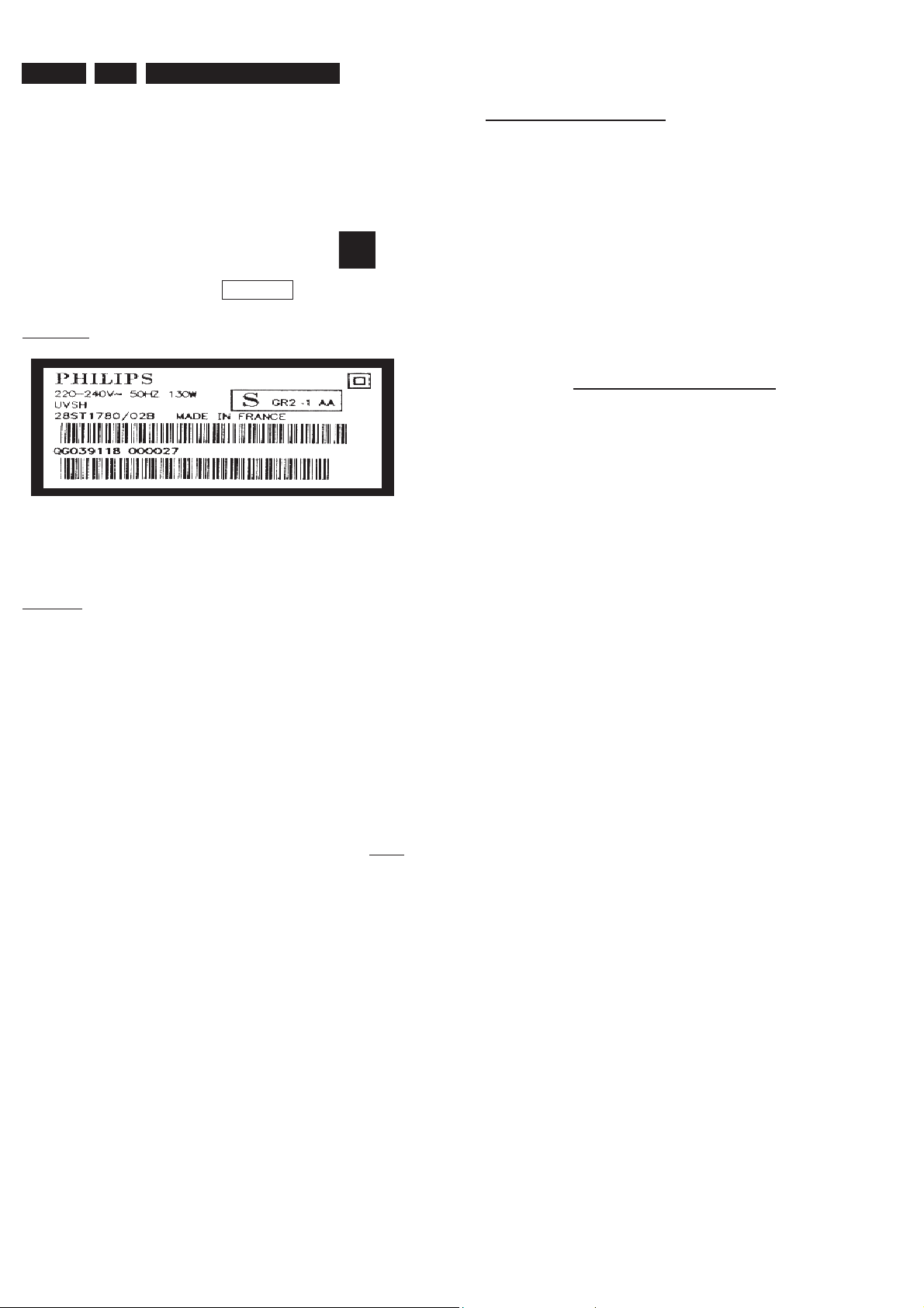
INDENTIFICATION:
Regardless of special logo (not always indicated)
One must treat all sets from 1 Jan 2005 onwards, according
next rules.
Example S/N:
Bottom line of typeplate gives a 14-digit S/N. Digit 5&6 is the year, digit 7&8 is
the week number, so in this case 1991 wk 18
So from 0501 onwards = from 1 Jan 2005 onwards
• Special information for BGA-ICs:
- always use the 12nc-recognizable soldering temperature
profi le of the specifi c BGA (for de-soldering always use the
lead-free temperature profi le, in case of doubt)
- lead free BGA-ICs will be delivered in so-called ‘drypackaging’ (sealed pack including a silica gel pack) to
protect the IC against moisture. After opening, dependent
of MSL-level seen on indicator-label in the bag, the
BGA-IC possibly still has to be baked dry. (MSL=Moisture
Sensitivity Level). This will be communicated via AYSwebsite.
Do not re-use BGAs at all.
• For sets produced before 1.1.2005 (except products of
2004), containing leaded solder-alloy and components,
all needed spare-parts will be available till the end of the
service-period. For repair of such sets nothing changes.
• On our website www.atyourservice.ce.Philips.com you
fi nd more information to:
BGA-de-/soldering (+ baking instructions)
Heating-profi les of BGAs and other ICs used in Philips-sets
You will fi nd this and more technical information within the
“magazine”, chapter “workshop news”.
For additional questions please contact your local repair-helpdesk.
Important note: In fact also products of year 2004 must be treated in this way as long as you
avoid mixing solder-alloys (leaded/ lead-free). So best to always use SAC305 and the higher
temperatures belong to this.
Due to lead-free technology some rules have to be respected by the
workshop during a repair:
• Use only lead-free solder alloy Philips SAC305 with order
code 0622 149 00106. If lead-free solder-pate is required,
please contact the manufacturer of your solder-equipment.
In general use of solder-paste within workshops should be
avoided because paste is not easy to store and to handle.
• Use only adequate solder tools applicable for lead-free
solder alloy. The solder tool must be able
o To reach at least a solder-temperature of 400°C,
o To stabilize the adjusted temperature at the solder-tip
o To exchange solder-tips for different applications.
• Adjust your solder tool so that a temperature around 360°C
– 380°C is reached and stabilized at the solder joint.
Heating-time of the solder-joint should not exceed ~ 4 sec.
Avoid temperatures above 400°C otherwise wear-out of
tips will rise drastically and fl ux-fl uid will be destroyed. To
avoid wear-out of tips switch off un-used equipment, or
reduce heat.
• Mix of lead-free solder alloy / parts with leaded solder alloy
/ parts is possible but PHILIPS recommends strongly to
avoid mixed solder alloy types (leaded and lead-free).
If one cannot avoid or does not know whether product is
lead-free, clean carefully the solder-joint from old solder
alloy and re-solder with new solder alloy (SAC305).
• Use only original spare-parts listed in the Service-Manuals.
Not listed standard-material (commodities) has to be
purchased at external companies.
Page 3
123456
0803 E4
1700 E1
2700 A2
2701 B3
2702 A2
2703 D3
A
1
B
A
C
B B
D
1700
TMQZ2
owner.
is prohibited without the written consent of the copyright
All rights reserved. Reproduction in whole or in parts
E
C
F
D
G
2705 E3
2707 C3
7701
BC857BW
I700
3704
100R
I701
1920
VIDOUT
RFAGC
TUNER
SIFOUT
VFV
to IOV,FOME
F705
18
AFT
GND2
VTU
NC5
MB
SDA
SCL
GND1
AOUT
NC4
NC3
NC2
NC1
BB
21
2708 C4
2709 B3
2710 C1
3706
2K2
17
16
15
14
13
12
10
11
9
8
7
6
5
4
3
2
1
2711 C1
2712 D4
3700 A2 5706 D4
3701 A2
3704 B1
3706 A1
5700 A22704 E3
5702 D3
5703 C4
23
5V
SIF1
to MSP
5700
22u
2711
2701
25V
22u
6.3V47u
F704
2710
F703
F702
2700
22n
3700
47K
3701
47K
I703
F701
2702
not used
100n
5704 C4
5705 D3
2709
I704
I706
10n
5705
10n
Bead
2703
7701 A1
F700 D1
F701 E3
5VSTBY
5VSTBY
2707
delete for DTTM
100n
F702 D3
F703 D3
F704 C3
from PS
5704
Bead
47p
not used
33VSTBY
5702
10u
F705 B1
I700 A1
I701 B1
I703 B2
I704 C3
I705 C4
I706 C3
I707 C4
A
4
5V
33VSTBY
B
5V
33VSTBY
A
C
D
E
C
F
D
G
2708
5703
Bead
47p
not used
2712
I705
I707
5706
10u
25V10u
for DTTM only
SCL_5V
from CU
SDA_5V
from/to CU
5VSTBY
-403A
E
H
I
CHN SETNAME dvdrw_2004
CLASS_NO
3PB120
J
2004-03-2623
NAME
1
Frontend Video FV
Friedreich
CHECK DATE
PB AB 04 E1
SUPERS.
123456
2003-01-13
50V4u7
10n
50V
2704
2705
0803
BARCODE
E
H
I
21
10
3
3103 603 3035
C
ROYAL PHILIPS ELECTRONICS N.V. 2005
130
4
2006-01-27
7
6
2005-07-07
0
2004-10-22
0
2004-05-07
0
2004-03-25
1
J
A4
Page 4
1 2 3 4 5 6 7 8 9 10 11 12 13 14 15 16 17 18 19
20
A
12VSTBY
5VSTBY
B
A
12VSTBY
5VSTBY
C
B
D
E
C
WU
to CU
BC857BW
I404
2402
220n
F
D
G
E
H
I
F
J
G
WSFI
to CU
K
AINFL
to IOA
AINFR
All rights reserved. Reproduction in whole or in parts
is prohibited without the written consent of the copyright
owner.
L
H
M
to IOA
1942
AINFR
GND
AINFL
CVBSFIN
GND
NC
CFIN
GND
from/to FRONT A/V
YFIN
1
2
3
4
5
6
7
8
9
B9B-PH-K
I
N
1
from PS
5V
5V
5VSTBY
7403
3K9
3408
I405
F4201
F4203
F4204
F4207
F4209
5NSTBY
5NSTBY
BC857BW
I406
3405
5VSTBY
7401
22K
from PROG
BC847BW
82K
3489
10u 16V
5NESD
5NESD
5VSTBY
7402
2450
I407
3406
not used
2428
2421
10u16V
100n
470K
2412
I409
3407
5NSTBY
10n
I408
3K3
3429
47K
CVBSIN
3446
3447
to FOME
47K
47K
2459
100n
2401
2410
3490
SCART 1
3404
100p
not used
100n
150R
2404
3435
I422
I423
F4021
1%
75R
6401
5NESD
100n
150R
I419
I420
CVBSIN1
GND
20A
21A
F4020
BZX384-C12
3445
I418
YCVBSOUT1
19A
F4019
6420
150R
1%
75R
3414
7412
NJM2234M
43
GND
GND
17A
18A
F4016
6414
BZX384-C6V8
BZX384-C6V8
3412
3-INPUT
VIDEO SW
1
VIN1
3
VIN2
5
VIN3
2
SW1
4
SW2
I421
NJM2235M
3-INPUT
VIDEO SW
1
VIN1
3
VIN2
5
VIN3
2
SW1
4
SW2
FBOUT
16A
F4015
3409
75R
Φ
GND
7413
Φ
GND
RCOUT
15A
6402
1%
75R
5V
V+
VOUT
8
5V
6
V+
VOUT
8
GND
GND
13A
14A
6403
BZX384-C6V8
2406
1u0
6
7
2407
1u0
5
NC
12A
F4011
BZX384-C6V8
3413
7
GOUT
11A
F4010
1%
75R
3422
I402
5VSTBY
5V
3437
P50
10A
3430
2403
10K
GND
9A
6423
BAT54 COL
820R
4K7
100n
5V
3438
8SC1
BOUT/CIN
8A
F4008
F4007
BZX384-C12
6421
6410
BAS316
7404
BC817-25W
10K
7A
F4006
5NESD
3403
AIN1L
6A
6404
1%
75R
62
GND
GND
4A
5A
F4003
BZX384-C12
2424
12VSTBY
7405
BC847BW
7407
BC847BW
2419
1u0
7416
BC847BW
AOUT1L
3A
F4002
470p
5NESD
I467
BC847BW
33K
3424
3410
75R
2413
1u0
AOUT1R
AIN1R
2A
F4001
6405
BZX384-C12
12VSTBY
7409
1%
5VSTBY
3451
2417
16V 10u
1A
10K
1940-1
2425
3421
3423
3450
ROW_A
27K
390R
BC847BW
3428
100K
7
AIN1R
MRC-021V-10 PC
6406
3443
3426
2447
10n
not used
1u0
from FV
VFV
3472
BZX384-C12
7414
BC857BW
47K
33K
3442
470p
5NESD
7415
2446
100K
to IOA,MSP
2426
100K
3441
470K
150K
5VSTBY
3439
F444
3433
100R
from/to CU
SDA_5V
3475
6407
470p
5NESD
3448
10K
I461
I462
I463
I464
I465
I466
I415
I416
I417
I468
I401
I403
I469
I470
3432
SCL_5V
from IOA
AOUT1R
100R
2429
BZX384-C12
3444
18K
100K
2411
34
33
40
41
1
43
28
42
44
2
14
16
18
38
37
100R
from/to CU
8
from IOA
AOUT1L
3476
100R
470p
6408
BZX384-C12
5NESD
5VSTBY
2414
100n
100n
20
36
VDD
VCCB-REC
R|PR|COUT-TV
G|YOUT-TV
B|PBOUT-TV
FBOUT-TV
Y|CVBSOUT-TV
CIN-TV
Y|CVBSIN-TV
Y|CVBSIN-TUN
CIN-TUN
C-GATE
1
VS
CS
2
3
DIGOUT
4
5
6
SDA
SCL
GNDB-REC
22
AIN1L
3471
8
VCC
to IOA,MSP
100K
I456
2435
7408
STV6618D
P50
from/to CU
6409
BZX384-C6V8
5VSTBY
5406
2434
100n
Φ
MRC-021V-10 PC
10u
6.3V47u
VIDEO SWITCH
MATRIX
Y|CVBSOUT-REC
Y|CVBSOUT-AUX
GND1
GND2
3
12
9
MT2
1940-3
MT1MT2
4401
not used
24
30
32
VCCB3
VCCB2
VCCB1
R|PR|CIN-ENC
G|YIN-ENC
B|PBIN-ENC
CVBSIN-ENC
CIN-ENC
YIN-ENC
DECV
COUT-AUX
R|PR|CIN-AUX
G|YIN-AUX
B|PBIN-AUX
FBIN-AUX
Y|CVBSIN-AUX
GNDB
GNDD
39
26
I414
2409
1029
1127
21
23
25
17
15
13
35
19
3427
5VSTBY
100n
931
4
6
7
5
SCART 2
1%
75R
6424
5NESD
10u
5402
2405
47u 6.3V
I483
2441
I482
1u0
I481
2437
1u0
I479
2438
I478
1u0
2433
47n
I476
3449
75R
2418
1u0
2427
1u0
3452
150R
GND
21B
F4121
F4120
BZX384-C12
2440
1u0
2436
1u0
2439
1u0
2423
1u0
3494
150R
10
YCVBSIN2
CVBSOUT2
20B
19B
F4119
3411
2416
1u0
GND
18B
6419
BZX384-C6V8
75R
GND
17B
FBIN
16B
F4116
GND
RCIN
15B
F4115
3401
75R
6415
BZX384-C12
6422
BZX384-C6V8
3417
75R
GND
14B
1%
5VSTBY
2408
11 12 13
13B
3491
3436
NC
12B
F4211
5NESD
5NESD
3492
150R
4K7
100n
GIN
P50
10B
11B
F4110
3402
1%
75R
6416
BZX384-C12
150R
3425
7406
BC817-25W
GND
9B
75R
F4108
5NESD
1%
8SC2
8B
F4107
3493
BIN/COUT
AIN2L
6B
7B
F4106
2431
150R
5NESD
GND
470p
6425
5NESD
6417
5B
GND
AOUT2L
3B
4B
F4103
3470
BZX384-C12
BZX384-C12
5VSTBY
3431
2422
AIN2R
F4102
100K
4K7
3434
4K7
10n
2B
F4101
2443
6418
100n
2415
AOUT2R
1940-2
1B
470p
6412
5NESD
BZX384-C12
I411
ROW_B
5V
3416
3418
to IOA
to IOA
AIN2L
AIN2R
MRC-021V-10 PC
3469
100K
BZX384-C12
F4720
5V
27K
22K
3415
I410
I412
3420
2442
F4701
F4703
F4705
F4707
F4709
F4712
F4714
F4716
F4718
F4721
F4722
1K0
3440
100R
7411
BC847BW
100R
I451
3478
6411
470p
5NESD
3419
100R
AOUT2L
14
from MSP
2444
1947
100n
I413
3477
470p
6413
5NESD
A_VR
GND
A_UB
GND
A_YG
GND
A_C
GND
A_YCVBS
GND
GND
D_CVBS
GND
D_Y
GND
D_C
GND
D_VR
GND
D_YG
GND
D_UB
5V
7410
BC857BW
2420
100R
BZX384-C12
1
2
3
4
5
6
7
8
9
10
11
12
13
14
15
16
17
18
19
20
21
22
22FMN-BTRK-A
2430
from MSP
AOUT2R
100R
BZX384-C12
2432
100n
1940-1 A7
1940-2 A13
1940-3 A9
1942 H1
1947 C14
2401 B3
2402 C1
2403 E5
2404 F3
2405 E9
2406 F5
2407 H5
2408 H11
2409 E9
A
2410 E3
2411 D8
2412 G2
2413 F6
2414 D8
2415 H12
2416 H10
2417 H6
2418 G9
2419 F6
2420 I14
2421 I2
2422 I12
B
2423 G10
2424 B6
2425 B7
8SC2
to CU
FB
to CU
2426 B7
2427 G9
2428 H2
2429 B8
2430 G14
2431 B12
2432 G14
2433 F9
2434 D8
C
2435 D8
2436 E10
2437 F9
2438 F9
2439 F10
2440 E10
2441 E9
2442 B13
2443 B12
2444 B14
2446 G7
2447 E7
2450 C2
D
2459 G3
3401 B11
3402 B11
3403 D6
3404 B3
3405 C1
3406 C2
3407 C2
from/to DIGTAL BOARD
3408 C1
3409 B4
3410 E6
3411 B10
3412 C4
E
D_VR
to PROG
D_YG
to PROG
D_UB
to PROG
D_CVBS
to PROG
3413 B5
3414 C4
3415 G13
3416 G13
3417 B11
3418 H13
3419 H14
3420 I13
3421 C6
3422 C5
3423 D6
D_Y
to PROG
F
3424 D6
3425 H11
3426 D7
3427 B9
3428 D7
3429 G2
3430 D5
3431 I12
3432 H7
3433 H7
3434 I13
3435 G3
3436 H11
3437 H5
G
3438 H5
3439 E7
3440 H13
22u 16V
3441 C7
3442 D7
3443 C7
3444 D8
3445 C4
3446 B3
3447 B3
3448 D7
3449 G9
3450 H7
H
3451 G6
3452 H9
3469 B13
3470 B12
3471 B8
3472 B7
3475 A7
3476 A8
3477 A14
3478 A13
3489 G2
CRout
to PROG
I
3490 F3
3491 C11
3492 C11
3493 C12
3494 G10
4401 A9
5402 D9
5406 D8
6401 B3
6402 B4
6403 B5
6404 B6
6405 B6
6406 B7
6407 B7
6408 B8
6409 B8
6410 C5
6411 B13
6412 B13
6413 B14
6414 B4
6415 B11
6416 B11
6417 C12
6418 C12
6419 B10
6420 B4
6421 C5
6422 B11
6423 B5
6424 B9
6425 B12
7401 C2
7402 B2
7403 C1
7404 D5
7405 C6
7406 H11
7407 D6
7408 E8
7409 D7
7410 H14
7411 H13
7412 G4
7413 I4
7414 C7
7415 D7
7416 H6
F4001 A6
F4002 A6
F4003 A6
F4006 A6
F4007 A5
F4008 A5
F4010 A5
F4011 A5
F4015 A4
F4016 A4
F4019 A4
F4020 A4
F4021 A3
F4101 A12
F4102 A12
F4103 A12
F4106 A12
F4107 A12
F4108 A11
F4110 A11
F4115 A10
F4116 A10
F4119 A10
F4120 A10
F4121 A10
F4201 H1
F4203 H1
F4204 H1
F4207 H1
F4209 I1
F4211 A11
F444 G7
F4701 C13
F4703 C13
F4705 D13
F4707 D13
F4709 D13
F4712 D13
F4714 D13
F4716 D13
F4718 E13
F4720 E13
F4721 E13
F4722 E13
I401 G7
I402 C5
I403 H7
I404 C1
I405 G1
I406 C2
I407 C2
I408 B2
I409 B2
I410 H13
I411 H13
I412 H13
I413 H14
I414 D9
I415 G7
I416 G7
I417 G7
I418 G4
I419 G4
I420 G4
I421 H4
I422 I3
I423 I3
I451 I13
I456 D8
I461 E7
I462 E7
I463 E7
I464 F7
I465 F7
I466 F7
I467 D6
I468 G7
I469 H7
I470 H7
I476 F9
I478 F9
I479 F9
I481 E9
I482 E9
I483 E9
A
B
C
D
E
F
G
H
I
J
K
L
M
N
O
P
1
2
3
4
65
7
8
9
654321 201918171615
10 11 12
CHN SETNAME dvdrw_2004
CLASS_NO
3PB120
1
2
2004-03-26
NAME
Neubauer
3
CHECK
1413121110987
13 14
PB AB 04 E1
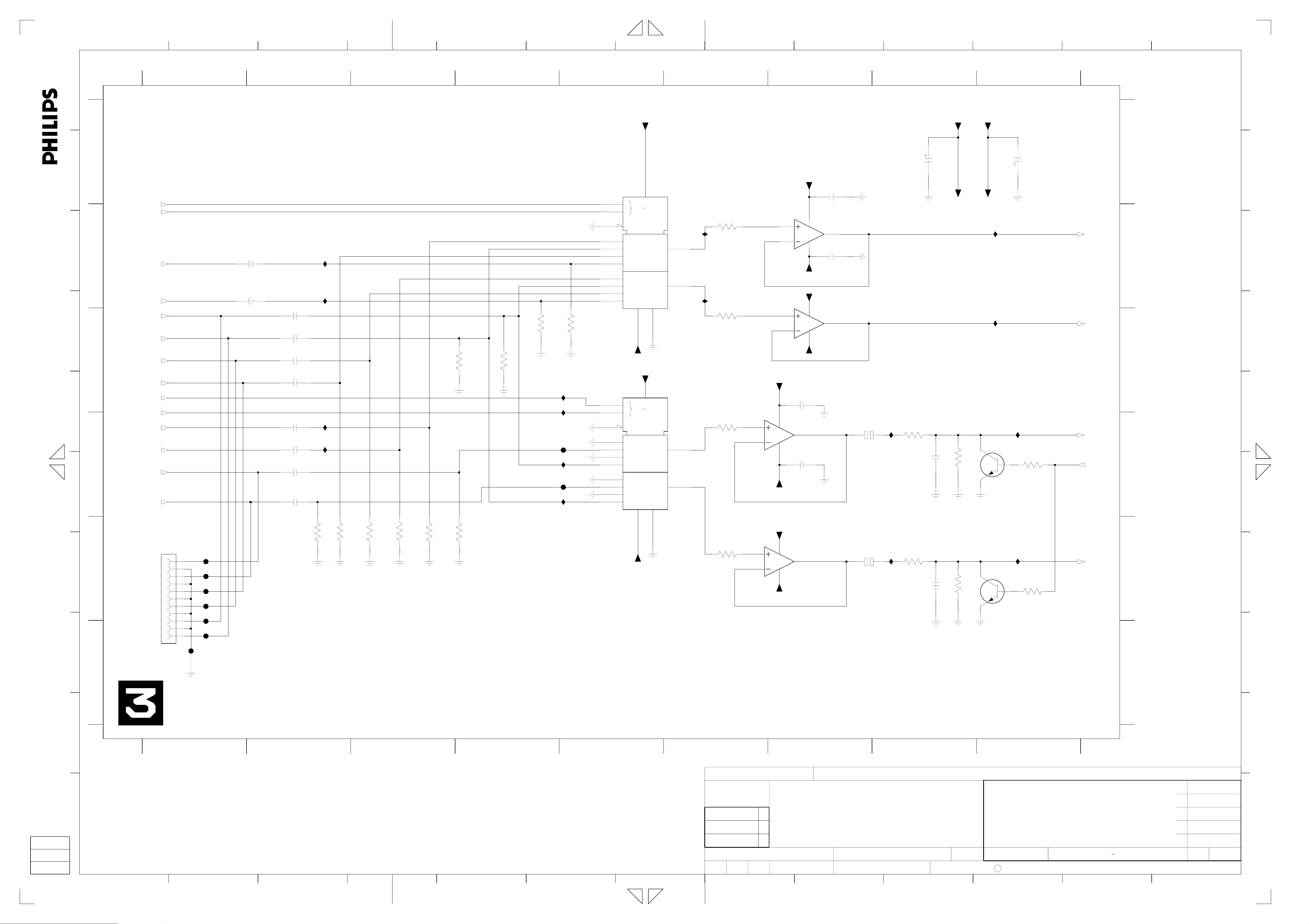
Video In/Out IOV
SUPERS.
DATE
2003-01-13
10
O
7
2006-01-27
6
2005-07-07
0
2004-10-22
3103 603 3035
0
2004-05-27
0
2004-05-07
2
130
C
ROYAL PHILIPS ELECTRONICS N.V. 2005
A2
P
Page 5
1234 56
A
A
B
RSA2
RSA1
from MSP
C
D
All rights reserved. Reproduction in whole or in parts
is prohibited without the written consent of the copyright
owner.
E
B
C
D
AINFR
from IOV
AINFL
from IOV
AIN2L
from IOV
AIN2R
from IOV
AIN1L
from IOV
AIN1R
from IOV
IMUTE
from CU
ASC1
from CU
AFER
from MSP
AFEL
from MSP
ALDAC
from DAC_ADC
F
ARDAC
from DAC_ADC
ALDAC
G
E
H
GND
ARDAC
GND
AIN1R
GND
AIN1L
GND
AIN2L
to AUX AV
GND
AIN2R
for RECEIVER only
1
F510
F509
F508
F507
F505
F506
F503
2508
1u0
2507
1u0
2
2501
1u0
2506
1u0
2504
1u0
2505
1u0
2525
1u0
2524
1u0
2513
1u0
X5R
2515
1u0
X5R
I514
I516
I502
I504
3507
3534
100K
100K
3510
100K
3
3516
100K
3514
100K
3504
3511
100K
100K
7
45
5VSTBY
7501
3503
100K
3506
100K
I527
I521
F502
I515
F501
I513
3505
100K
HEF4052B
10
9
6
12
14
15
11
1
5
2
4
7504
HEF4052B
10
9
6
12
14
15
11
1
5
2
4
0
1
G4
0
1
2
3
0
1
2
3
5NSTBY
0
1
G4
0
1
2
3
0
1
2
3
5NSTBY
16
VDD
0
4X
3
MDX
VEE VSS
7
8
5VSTBY
16
VDD
0
4X
3
MDX
VEE VSS
7
8
13
3
13
3
I518
I517
6
3509
1K0
3502
1K0
3523
1K0
3515
1K0
8 9 10 11 12 13
1950 E1
7
8
from PS
5VSTBY
6.3V
2510
47u
5VSTBY
2521
100n
7509-2
5
6
3
2
5VSTBY
7505-2
5
6
3
2
84
MC33078D
5NSTBY
5VSTBY
7505-1
84
MC33078D
5NSTBY
84
5NSTBY
5VSTBY
84
5NSTBY
2531
100n
7
2532
100n
1
MC33078D
7
2530
100n
7509-1
MC33078D
1
2526
100u 16V
2522
100u
16V
I540
I535
3525
220R
2527
3522
220R
2523
5VSTBY
1n0
3527
1n0
3524
5NSTBY
5NSTBY
I528
I505
7506
BC817-25W
820R
7508
BC817-25W
820R
2519
I506
I507
9
6.3V
47u
3517
4K7
3519
4K7
ARADC
to DAC_ADC
ALADC
to DAC_ADC
AOUT1L
to IOV
AKILL
from DAC_ADC
AOUT1R
to IOV
A
B
C
D
E
2501 C2
2504 C2
2505 C2
2506 C2
2507 B2
2508 B2
2510 A8
2513 D2
2515 D2
2519 A9
2521 A7
2522 E7
2523 E8
2524 D2
2525 D2
2526 D7
2527 D8
2530 B7
2531 C7
2532 D7
3502 C6
3503 C4
3504 C3
3505 C5
3506 C4
3507 E4
3509 B6
3510 E3
3511 E3
3514 E3
3515 E6
3516 E3
3517 D9
3519 E9
3522 E8
3523 D6
3524 E8
3525 D8
3527 D8
3534 E2
7501 A5
7504 C5
7505-1 D7
7505-2 E7
7506 D9
7508 E9
7509-1 B7
7509-2 C7
F501 D5
F502 D5
F503 F1
F505 E1
F506 E1
F507 E1
F508 E1
F509 E1
F510 F1
I502 D2
I504 D2
I505 C9
I506 D9
I507 E9
I513 D5
I514 B2
I515 D5
I516 B2
I517 B6
I518 B6
I521 D5
I527 C5
I528 B9
I535 E8
I540 D8
A
B
C
D
E
F
G
H
J
F
F
I
I
1
2
3
45
6
CHN SETNAME dvdrw_2004
CLASS_NO
3PB120
7
PB AB 04 E1
1
89
7
6
0
2006-01-27
2005-07-07
2004-10-22
J
3103 603 3035
2
Audio In/Out IOA
0
2004-05-07
2004-03-26
NAME
1 89
234 56
7
Fischer
3
CHECK DATE
SUPERS.
2003-01-13
10 11 12 13
10
0
130
C
ROYAL PHILIPS ELECTRONICS N.V. 2005
3
2004-03-25
A3
Page 6
A
123
1351 A3
1352 A3
1353 B3
1932 A1
2352 D3
2353 E1
3358 D4
3361 C3
3362 D3
3363 C1
3364 C1
3365 D1
3366 D3
3367 D1
3368 D1
3369 E3
4701 A33360 C1 F362 B4
5351 A3
5352 B3
5353 B3
6352 D1
6353 E1 F367 A1
7351 E3
7352 D3
7353 D2
7354 D2
7355 E4
9702 B3
9703 B3
9704 C3 F375 B3
F351 A4
F352 A4
F353 A3
F354 A3
456
F355 A1
F356 A2
F357 A2
F358 A1
F359 A2
F360 A1
F361 A2
F363 A1
F364 A1
F365 A1
F366 A2
F368 A1
F369 A1
F370 D3
F371 E2
F372 E4
F373 A1
F374 B3
I351 D3
I352 D1
I353 D1
A
1932
12VSTBY
B
A A
C
B
D
owner.
is prohibited without the written consent of the copyright
All rights reserved. Reproduction in whole or in parts
E
STBY
5VSTBY
DD_ON
3V3STBY
IPFAIL
5NSTBY
GND
33VSTBY
GND
from POWER SUPPLY
VGNSTBY
B11B-PH-K
C
12VSTBY
F
4K7
3365
D
G
6352
BZX384-C8V2
100n
2353
6353
BAS316
E
H
1
3368
100R
F352
5VSTBY
F362
3V3STBY
7355
BC847BW
4
12VSTBY
STBY
from CU
5VSTBY2
to CU
5VSTBY
to IOV,IOA,DAC_ADC,CU
DD_ON
from CU
3V3STBY
IPFAIL
to DAC_ADC
5NSTBY
to IOA,IOV,PROG,CU,
DAC_ADC
33VSTBY
to FV
VGNSTBY
to CU
to IOV,FOME,FV,MSP,
DAC_ADC,DIGIO,PROG,CU
10K
3358
F372
to IOV,CU
to CU
5V
3V3SW
to DAC_ADC
8VSTBY
to MSP
B
C
D
E
B
C
D
E
F
G
H
2
F357
F373
1
F368
2
F358
3
4
5
6
7
8
9
10
11
I353
F369
F360
F367
F363
F365
F355
F364
F359
F361
F366
F356
12VSTBY
3360
3363
3364
3367
I352
7354
BC847BW
47R
47R
33R
33R
F371
7353
PDTC124EU
3V3STBY
3361
I351
3366
1352
800mA
9702
1353
125mA
not used
2M2
2352
100n50V
2M2
3369
3
4701
1351
500mA
not used
F353
F374
5VSTBY
100K
7351
BC857BW
F354
F375
5353
10u
9704
not used
7352
SI2306DS
5351
22u
5352
10u
9703
not used
F370
3362
3K3
F351
12VSTBY
I
1
CHN SETNAME dvdrw_2004
CLASS_NO
3PB120
J
2004-03-2623
NAME
1
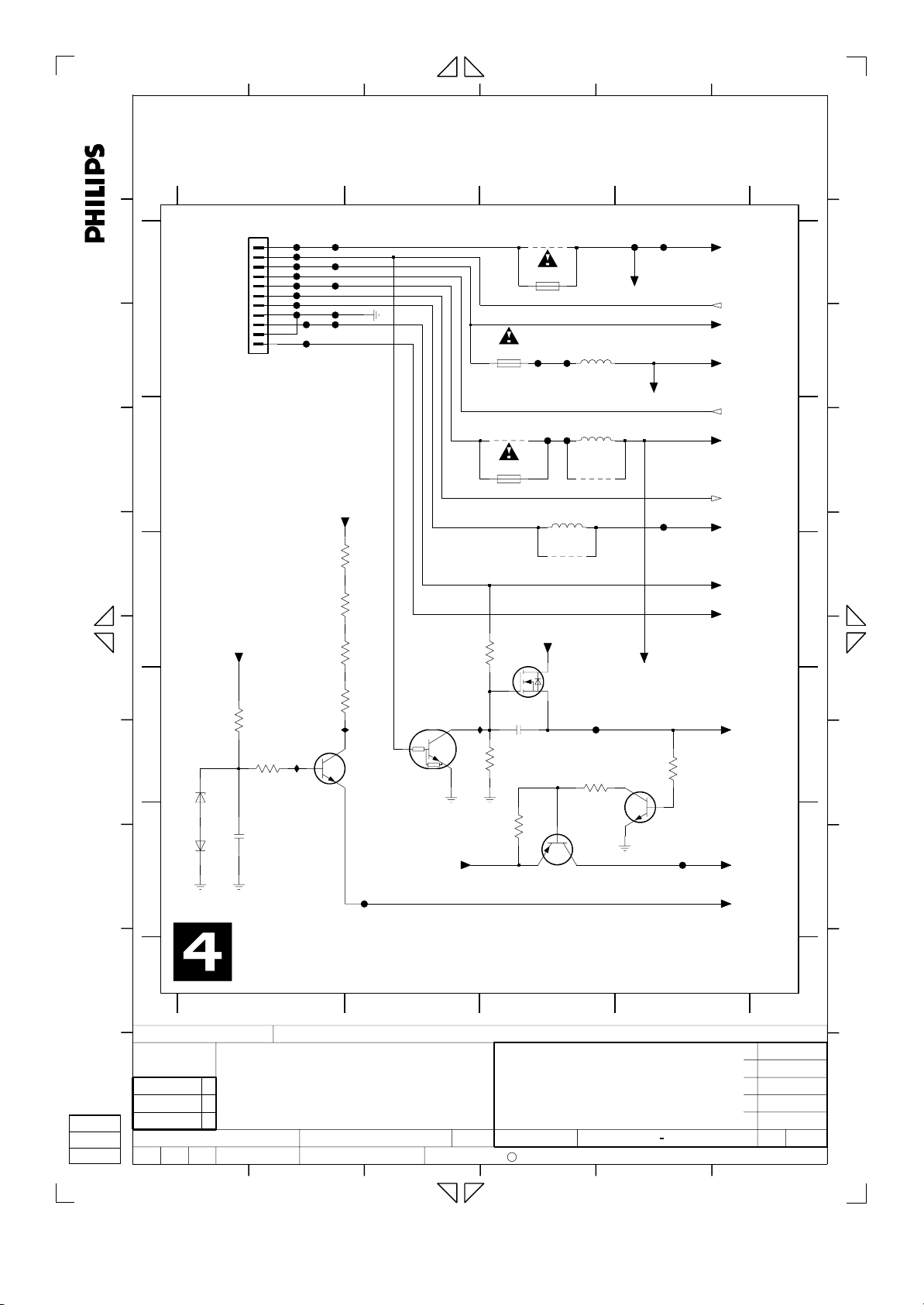
Power Supply PS
Folzberger
CHECK DATE
PB AB 04 E1
SUPERS.
123456
2003-01-13
I
2
10
34
3103 603 3035
4
130
C
ROYAL PHILIPS ELECTRONICS N.V. 2005
7
6
0
0
0
2006-01-27
2005-07-07
2004-10-22
2004-05-07
2004-03-25
A4
J
Page 7
1234 56
7
8 9 10 11
12 13
A
A
B
SCL_5V
from/to CU
SDA_5V
from/to CU
C
B
D
SIF1
C
All rights reserved. Reproduction in whole or in parts
is prohibited without the written consent of the copyright
owner.
E
from FV
D
AIN1R
from IOV
F
AIN1L AOUT2R
from IOV
ARDAC
from DAC_ADC
from DAC_ADC
ALDAC
E
G
H
F
I
3616
2K2
3617
2K2
1
8VSTBY
2624
2625
2u2 50V
from PS
3603
100R
50V2u2
5V8VSTBY
5V
3619
12K
3601
100R
I607
3618
2605
2626
12K
10u 25V
2607
56p
2609
56p
3614
1K0
3615
1K0
1u0
1u0 50V
2630
2627
1u0
2631
50V1u0
I615
I616
I606
I608
7600
MSP3415G
12
I2C_CL
13
I2C_DA
14
I2S_CL
15
I2S_WS
16
I2S_DA_OUT
17
I2S_DA_IN1
21
I2S_DA_IN2
3 ANA_IN-
2 ANA_IN+
43 MONO_IN
41 SC1_IN_R
40 SC1_IN_L
38 SC2_IN_R
37 SC2_IN_L
3
DEMODULATOR
VREF2
25
VREF1
29
AHVSS
35
18
ADR_CL
IDENT
A/D
A/D
ASG
39
I602
10
ADR_SEL
4
AVSS
44
RSA1
3611
I624
8
D_CTR_IO1
S1...4
FM1
FM2
NICAM A
NICAM B
IDENT
SCART-L
SCART-R
SCART
DVSS
20
to IOA
10K
3612
I625
52
RSA2
to IOA
10K
4
9
TESTEN
D_CTR_IO0
I2SL/R
DFP
Switching Facilities
NC
23
24
I2SL/R
LOUDSPEAKER R
LOUDSPEAKER L
HEADPHONE R
HEADPHONE L
28
5V
SCART-R
SCART-L
32
5602
10u
2600
AVSUP
1
I613
2623
25V10u
D/A
D/A
100n
10n
2601
42
VREFTOP
D/A
D/A
TP
7
6
8VSTBY
2602
33
AHVSUP
LOUDSPEAKER
XTAL_IN6XTAL_OUT
5
I610
2620
1600
18M432
3p3
10u 25V
34
CAPL_M
STBYQ
DVSUP
RESETQ
AGNDC
2603
2621
100n
2611
11
19
22
26DACM_R
27DACM_L
36
30SC1_OUT_R
31SC1_OUT_L
I611
3p3
7
16V47u
I614
I605
I617
I618
I619
2618
2612
I620
I623
2628
3604
12K
1n0
50V4u7
1n0
2610
2629
3605
2619
10n
1n0
22K
1n0
2613
2614
6600
25V10u
25V10u
5V
3602
BAS316
2608
I621
I622
8
PDTC124EU
4K7
10u
3606
220R
3607
220R
7601
2622
5V
5600
2606
2615
1n0
not used
10u
100n
I612
1n0
not used
I634
9
7602
BC817-25W
7603
BC817-25W
3609
3610
4K7
4K7
STBY
from CU
AFER
to IOA
AFEL
to IOA
to IOV
AKILL
from DAC_ADC
AOUT2L
to IOV
A
B
C
D
E
F
1600 F6
2600 A6
2601 A6
2602 A6
2603 A7
2605 A2
2606 B8
2607 C2
2608 C8
2609 C2
2610 D7
2611 A7
2612 D7
2613 D8
2614 E8
2615 E8
2618 C7
2619 C7
2620 F6
2621 F7
2622 F8
2623 F5
2624 D1
2625 D1
2626 E2
2627 E2
2628 E7
2629 E7
3601 B2
3602 B8
3603 B2
3604 A7
3605 A7
3606 D8
3607 E8
3608 E8
3609 E9
3610 E9
3611 A4
3612 A5
3613 F8
3614 D2
3615 D2
3616 E1
3617 E1
3618 E1
3619 E1
5600 B8
5602 F5
6600 B8
7600 A3
7601 A8
7602 E9
7603 F9
I602 A4
I603 A6
I604 A6
I605 B7
I606 C2
I607 C2
I608 C2
I609 D7
I610 F6
I611 F7
I612 D8
I613 F5
I614 B7
I615 B2
I616 B2
I617 B7
I618 C7
I619 C7
I620 D7
I621 D8
I622 E8
I623 E7
I624 A4
I625 A4
I626 D2
I627 D2
I628 D2
I629 D2
I630 E1
I631 E2
I632 E1
I633 E2
I634 F8
A
B
C
D
E
F
G
H
I
J
1
2
34
5
6
CHN SETNAME dvdrw_2004
CLASS_NO
3PB120
1
7
PB AB 04 E1
8
9
7
6
0
2006-01-27
2005-07-07
2004-10-22
3103 603 3035
2
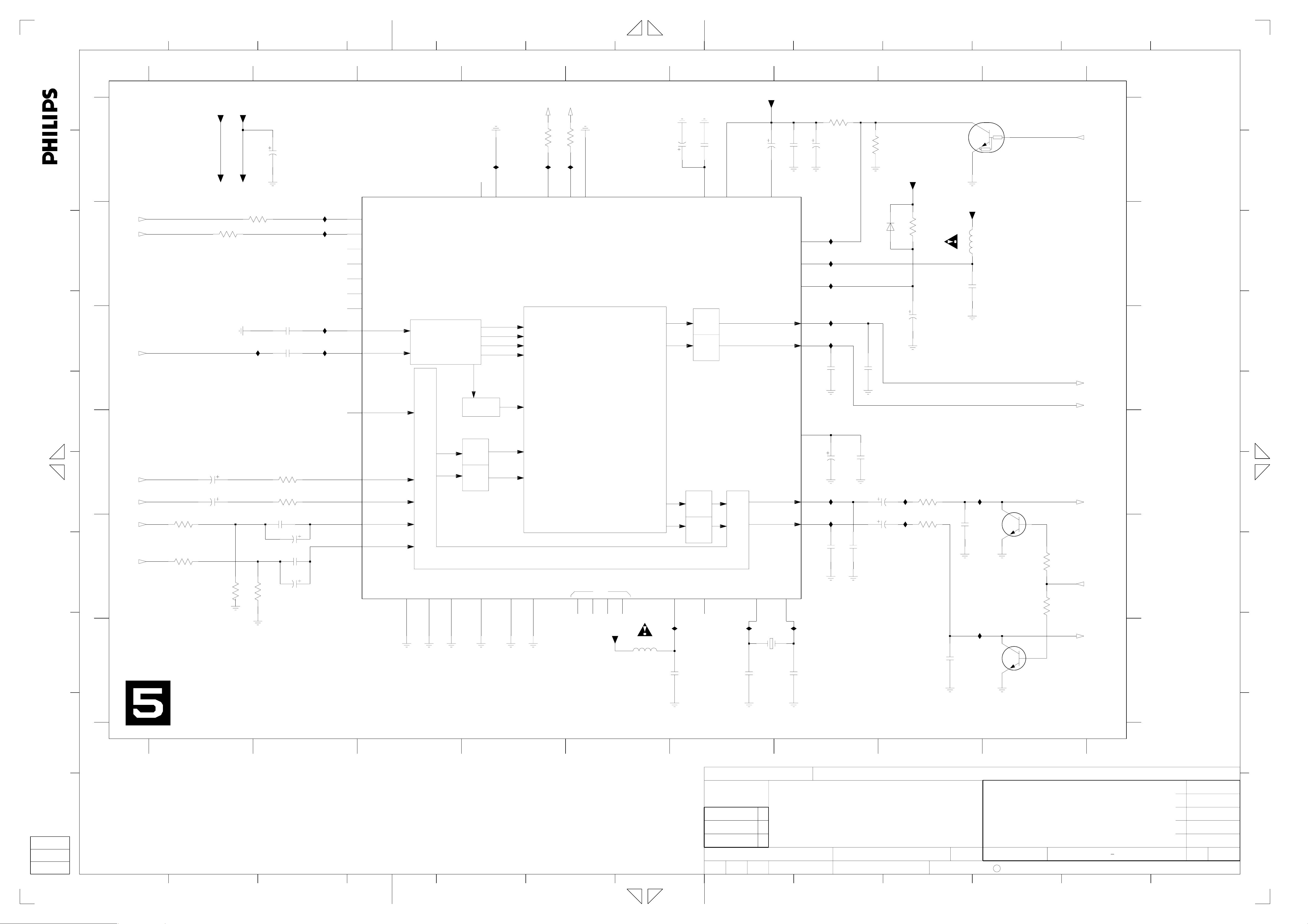
Multi Sound Processing MSP
2004-03-26
NAME
1 8 9 10 11 12 13
234 56
7
Posch K.H.
3
CHECK DATE
SUPERS.
2003-01-13
10
130
C
ROYAL PHILIPS ELECTRONICS N.V. 2005
5
0
0
2004-05-07
2004-03-25
J
A3
Page 8
1234 56
7
8 9 10 11 12 13
A
B
C
D
A
B
1920 A1 2216 B7
1921 C10 2217 C1
1922-A C5
1922-B A10
1922-C B5
1923 E5
2201 A8
2202 A4
2204 A7
2205 A3
2206 B2
2207 B5
2208 B7
1
1920
GND
Pr
GND
Pb
GND
Y
GND
from Digital Board
07FMN-BTRK-A
D_VR
from IOV
D_UB
from IOV
D_YG
from IOV
1
2
3
4
5
6
7
F203
F204
F205
2206
2210
22u 16V
2214
1u0
2209 B3
2210 B2
2211 B5
2212 B7
2213 B3
2214 B2
2215 B5
2 910
16V22u
2218 D2
2219 D3
2220 D7
2221 D8
2222 E72200 A5
2205
22u16V
2209
16V22u
2213
1u0
4601
I203
I207
I211
2223 E10
2224 E7
2225 E1
2226 E7
2227 E10
2228 E2
2229 E3
IPRO
from CU
3215
3216
3219
3
NJM2584M
I201
150R
150R
150R
2230 E7
2231 A9
2232 A9
2233 A9
2234 A9
2235 A10
2236 A10
7200
12
16
1
11
14
8
9
2237 A6
2239 A5
3200 A8
3201 B8
3202 B8
3203 B8
3204 C8
5V
5200
134
V+
Φ
3-CIRCUIT
VIDEO SW
CTL
IN1A
IN1B
IN2A
IN2B
IN3A
IN3B
GND
15
3205 D8
3206 C2
3208 D1
3209 D2
3210 E6
3211 E2
3213 E7
3214 E1
3215 C1
3216 C1
3217 E2
3218 E7
3219 C2
5200 A4
5201 D8
5202 C3
5203 E3
6200 B8
6201 B8
6202 B9
6203 D9
45
10u
F201
6.3V100u
2200
100n
I204
I208
I212
NC
OUT1
OUT2
OUT3
10
2
7
3
5
6
2202
100n
2239
2207
16V22u
2211
22u16V
2215
1u0
6204 D9
6205 D3
6206 D4
6207 E3
7200 A3
7201 A6
7202 D3
678
7201
NJM2580M
7
1
3
5
7203 D8
7204 E3
F201 A6
F202 A9
F203 A1
F204 A1
F205 A1
100n
2237
14
12
10
V+
Φ
3-CHANNEL
VIDEO AMP
PWR_SAVE
VIN1
VIN2
VIN3
GND
2
4
VSAG
VOUT1
VOUT2
VOUT3
6
13
11
F206 B9
F207 B9
F208 B9
F209 B9
F210 C8
F211 C8
F212 D9
F213 C4
F214 D4
F215 D8
F216 D4
I201 A3
I202 A7
I203 A3
I204 A6
I205 A7
I206 A8
I207 B3
I208 B6
I209 B7
I210 B8
I211 B3
I212 B6
I213 B7
I214 B8
I215 C7
I216 C1
I217 C2
I218 D2
I219 D7
I220 D8
I221 E9
I222 E8
I223 E1
I224 E2
I225 E8
I226 E9
I227 E8
I228 E2
A
from PS
5V
5NSTBY
B
3200
1K0
F202
2201
25V10u
2231
100n
2232
2233
100n
100n
2234
2235
100n
100n
2236
5NESD
to IOV
100n
A
5V
5NESD
I202
8
I205
I209
I213
9
2208
2212
2216
100u
6.3V470u
6.3V470u
6.3V
2204
47u 6.3V
I206
I210
I214
3201
75R
3202
75R
3203
75R
1%
1%
1%
F206
9
F207
10
F208
11
F209
1922-B
T-331520-10-10
V
U
Y
REAR OUT
B
8
C
D
All rights reserved. Reproduction in whole or in parts
is prohibited without the written consent of the copyright
owner.
E
C
F
ARDAC
from DAC_ADC
D
BKILL
G
H
E
from DAC_ADC
from DAC_ADC
2217
10u 16V
2225
16V10u
BKILL
from DAC_ADC
I216
3208
I223
3214
100K
100K
3206
270R
3209
470R
3211
270R
3217
470R
2218
I224
2228
I217
470p
I218
470p
I228
5202
Bead
7202
BC817-25W
5203
Bead
7204
BC817-25W
6205
5NESD
6207
5NESD
2219
470p
BZX384-C15
2229
470p
BZX384-C15
6206
5NESD
F213
F214
F216
BZX384-C12
REAR OUT
1922-C
T-331520-10-10
6
7
5
1922-A
T-331520-10-10
2
3
4
1
1923
1
2
3
4
LPR6520-G020G
Aud R
Aud L
CVBS
Aud R
Aud L
Aud R
Aud L
CVBS
for PROGRESSIVE only
I215
3210
75R
1%
I219
3213
100K
3218
2222
100u
6.3V
2224
6.3V100u
2226
100u 6.3V
2230
100u 6.3V
100K
3204
75R
2220
I220
I222
I225
I227
1%
F215
100n
2221
6200
5NESD
6201
BZX384-C12
5NESD
6202
BZX384-C12
5NESD
BZX384-C12
E
1921
TCS7927-24-401
1
5V
F210
F211
3
REAR OUT
4
S-VIDEO
F212
2
7
2223
4u7 50V
2227
50V4u7
5
6
CRout
from IOV
D_CVBSALDAC
from IOV
D_Y
from IOV
1%
6.3V47u
5201
V+
10u
7203
NJM2267M
7
Φ
3205
68R
6203
5NESD
6204
BZX384-C12
5NESD
BZX384-C12
DUAL 6dB
VIDEO AMP
4
3
5
6
VOUT1
VSAG1
VOUT2
VSAG2
GND
I221
VIN1
VIN2
2
1
I226
8
C
D
E
F
G
H
J
delete for PROGRESSIVE
I
I
12
3
4
5
6
CLASS_NO
3PB120
7
8
dvdrw_2004SETNAMECHN
9
PB AB 04 E1
1
10
7
6
0
2006-01-27
2005-07-07
2004-10-22
J
3103 603 3035
2004-03-26
NAME
Norbert Fischer
2
3
Progressive PROG
SUPERS.
DATECHECK
2003-01-13
10
130
C
ROYAL PHILIPS ELECTRONICS N.V. 2005
6
0
0
2004-05-07
2004-03-25
A3
1 8 9 10 11 12 13
234 56
7
Page 9
123456
2944 D4
2945 D2
2946 E1 3952 B3
2947 E3 7934-1 D1
from PS
5V
A
2941 B3
2942 D2
2943 D4
B
5V
A
C
B
D
owner.
is prohibited without the written consent of the copyright
All rights reserved. Reproduction in whole or in parts
E
C
5V
5V
F
2
7932
4K7
100n
7934-3
3
3945 E3
3946 E2
3948 A2
F950
2
LM339D5
to CU
FOME
4
3939
4K7
3950 A3
3953 B2
3950
12
I951
I952
100K
7933
BC847BW
3937 C1 7934-2 D3
3938 C1
3939 C2
3940 D1
3941 D3
3942 E1
3943 E1
1
7934-1
LM339D
14
3948
4K7
3951
22K
3953
4K7
5V
2940
BC847BW
3954
3937
2K2
3938
2K2
5V
5V
5V
3
3952
15K
2941
10u 25V
LM339D
7934-2
3954 C2
7932 B2
7933 B33947 E4
LM339D
7934-4
7
13
7934-3 A2
7934-4 A3
F950 A2
I951 B22940 A2
I952 B23951 B2
I956 D1
I957 D1
I958 D3
I959 D3
I960 E1
I961 E33944 E3
A
4
1
6
B
A
C
D
B
E
C
F
11
9
8
D
3940
G
E E
H
I
5V
10M
3942
I960
2946
CVBSIN
1
CHN SETNAME dvdrw_2004
CLASS_NO
3PB120
J
2004-03-2623
NAME
1
Follow Me FOME
Neubauer
CHECK DATE
PB AB 04 E1
SUPERS.
2942
I956 I958
2n2
2945
I957
33K
3943
1u0
from IOV
180p
33K
3946
33K
3941
5V
10M
2
10
2003-01-13
C
10
2944
2n2
2943
I959
180p
33K
33K
3945
3944
I961
2947
VFV
3
3947
33K
1u0
from FV
4
3103 603 3035
7
130
ROYAL PHILIPS ELECTRONICS N.V. 2005
123456
7
6
0
0
0
2006-01-27
2005-07-07
2004-10-22
2004-05-07
2004-03-25
A4
D
G
H
I
J
Page 10
1
A
A
B
C
B
DAINCOAX
to DAC_ADC
D
C
DAOUT
from DAC_ADC
All rights reserved. Reproduction in whole or in parts
is prohibited without the written consent of the copyright
owner.
E
D
F
DAINOPT
to DAC_ADC
E
G
0005
H
F
1
3253
750R
1%
BRACKET
234 56
I252
452
10n
10V1u0
2250
I254
3262
560R
1n0
2257
1924
HSJ1637-010510
5
4
3
2
1
F2401
3257
100K
3255
100K
G-Link
OUT
2255
100n
3254
100R
2256
100n
I258
IROUT
from CU
GLINK_TXD
from CU
GLINK_RXD
to CU
from PS
5V
5V
3266
3261
470R
560R
not used
3
7250-6
SN74HCU04D
I251
3265
100R
for DIGITAL COAX IN only
7250-1
SN74HCU04D
12
I256
3260
2K2
6251
6252
BZX384-C6V8
BZX384-C6V8
12
3258
10K
7250-3
SN74HCU04D
I253
56
7250-2
SN74HCU04D
34
7250-5
SN74HCU04D
11
7250-4
SN74HCU04D
98
for EPG only
6253
BZX384-C6V8
5V
3250
1
11
1
1
1
2267
470R
I250
2265
13
714
10
F2405
F2403
F2402
1n0
7
I255
3267
1K8
6
8 9 10 11 12 13
0001 E1
78
for DIGITAL COAX IN only
F251
2251
100n
6
2254
6250
150p
I257
3252
100R
5250
34
2
1
6RG
3264
100R
not used
3256
BZX384-C6V8
2266
100n
3259
75R
3251
82R
3269
180R
75R
F2503
F2502
5V
3263
2259
5V
3268
2262
47R
25V100n
47R
100n
F2603
F2602
F266
3
2
1
3
2
1
2
1
3
1926
YKC21-3416
1925
YKC21-3416
6255
VS
IN
GND
JFJ1000
for DIGITAL OPT IN only
F267
F250
1
3
2
6269
VS
OUT
GND
JFJ2000
9
DIGITAL
IN
CINCH
DIGITAL
OUT
CHINCH
DIGITAL
OUT
OPTICAL
DIGITAL
IN
OPTICAL
A
B
C
D
E
F
1924 E4
1925 C8
1926 B8
1927 A1
2250 A4
2251 B7
2252 B2
2254 C7
2255 C5
2256 C2
2257 D4
2259 E8
2262 F8
2265 A4
2266 C8
2267 F4
3250 A4
3251 C7
3252 B6
3253 C1
3254 C1
3255 B4
3256 B8
3257 A4
3258 B4
3259 C7
3260 C3
3261 C3
3262 C4
3263 D8
3264 D6
3265 B3
3266 C2
3267 F6
3268 E8
3269 F8
5250 C6
6250 B7
6251 F3
6252 F3
6253 F3
6255 D9
6269 E9
7250-1 C3
7250-2 C4
7250-3 C4
7250-4 D4
7250-5 D4
7250-6 B3
F2401 F4
F2402 F4
F2403 E4
F2405 E4
F250 F8
F2502 C8
F2503 C8
F251 D7
F2602 B8
F2603 B8
F266 D8
F267 E8
F2701 A1
F2702 A1
F2704 A1
F2706 A1
F2708 B2
I250 A4
I251 B3
I252 B4
I253 C3
I254 C4
I255 C6
I256 C3
I257 C7
I258 C2
A
B
C
D
E
F
G
H
J
I
I
1
2
3
4
5
6
CHN SETNAME dvdrw_2004
CLASS_NO
3PB120
78
PB AB 04 E1
**-**-**
1
9
7
6
0
2006-01-27
2005-07-07
2004-10-22
J
3103 603 3035
**-**-**
2004-03-26
NAME
1 8 9 10 11 12 13
234 56
7
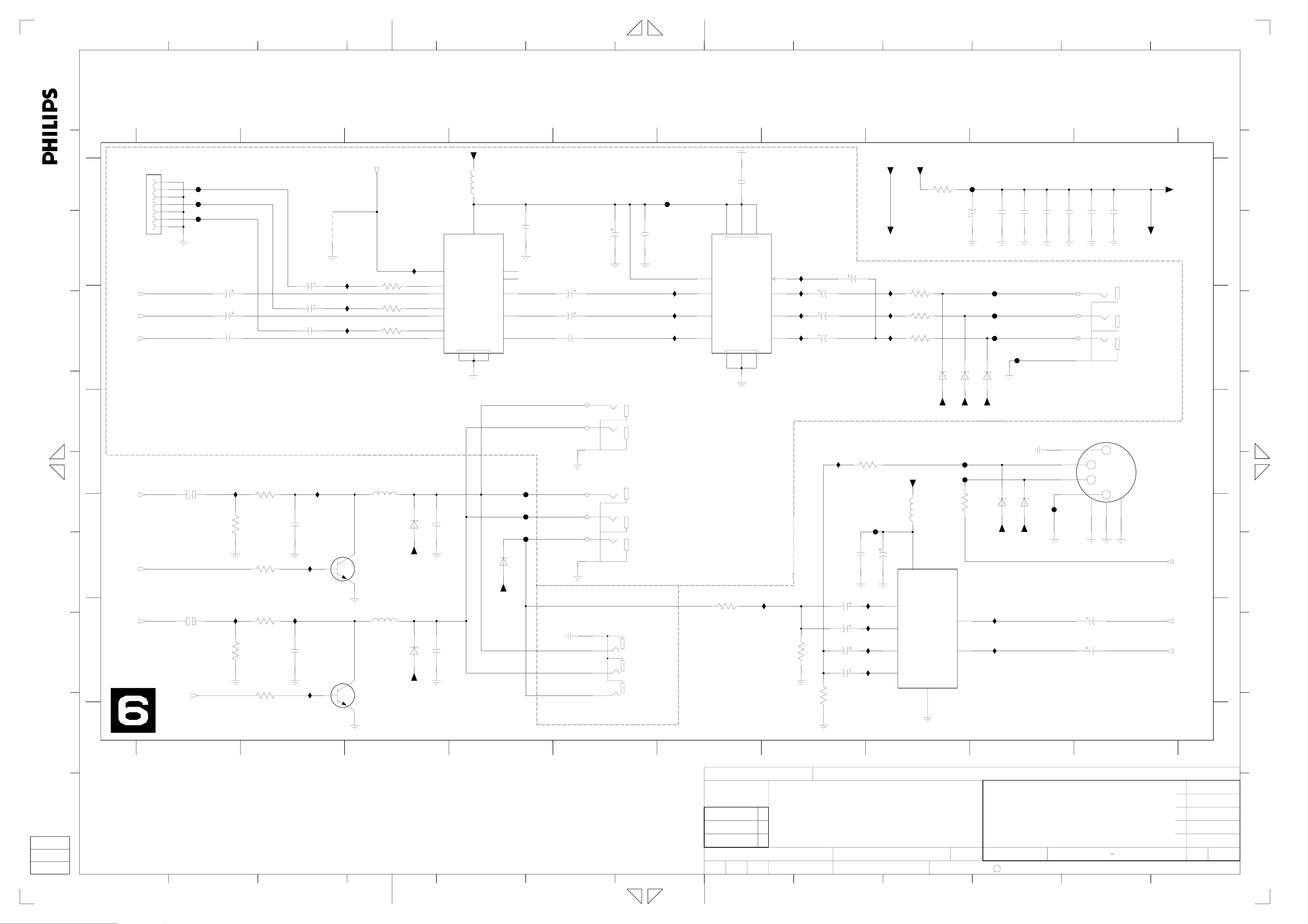
Fischer
2
3
CHECK DATE
Digital In/Out DIGIO
SUPERS.
**** *** *****
2003-01-13
10
0
0
130
C
ROYAL PHILIPS ELECTRONICS N.V. 2005
8
2004-05-07
2004-03-25
A3
Page 11
1234 56
7
8 9 10 11 12 13
A
1900 B1
2002 A5
2003 A5
2004 A6
2005 A1
2006 C8
2007 C9
2008 C8
2009 C9
2010 C10
2011 D10
2012 D10
2013 D9
2014 E10
B
AKILL
to IOA,MSP
A
C
IMUTE
from CU
IPFAIL
from PS
DAINOPT
from DIGIO
D
B
All rights reserved. Reproduction in whole or in parts
is prohibited without the written consent of the copyright
owner.
E
C
F
D
G
E
H
DAINCOAX
from DIGIO
DAOUT
to DIGIO
DAINCOAX
D_PCMCLK
D_DATA0
A_PCMCLK
from/to Digital Board
ARADC
from IOA
ALADC
from IOA
1900
GND
DAOUT
GND
DAINOPT
N.C.
D_KILL
GND
GND
D_WCLK
GND
D_BCLK
GND
GND
A_DAT
GND
A_WCLK
A_BCLK
GND
22FMN-BTRK-A
2015 A10
2017 C10
2018 C4
2019 C6
2020 C6
2021 C7
2023 C8
2025 C8
2030 D8
2032 D8
2033 D9
2035 D6
2037 D5
2038 D4
2041 E10
2042 E3
2043 E4
2045 E8
2047 E8
2048 E1
2050 D1
3001 B7
3003 D4
3004 C8 7003-1 B10
3005 B5
3006 B5
3007 E4
3008 B8
3009 C7
3010 B9
3011 A1
3012 C3
3013 C9
3014 D7
3015 A1
3016 C8
3017 C10
3018 E7
3019 C2
3020 B4
3021 B4
3022 C3
3023 C2
3024 C3
3025 A10
3026 D2
3027 D8
3028 D3
3029 A10
3030 D8
3031 B2
3032 D9
3033 D2
3034 C4
3036 E9
3037 A8
3039 E8
3040 E10
3046 A7
3047 E2
3050 A8
3053 D2
3054 C3
4001 E4
4002 E5
5000 A5
6003 B2
6004 B2
6005 B2
6006 A7
7001 B3
7002 A2
7003-2 D10
7004 A5
7005 A9
7006 C2
7007 D5
7010 A8
F001 B1
F002 B1
F003 B1
F004 C1
F005 C1
F006 A3
F007 C1
F008 C1
F009 D1
F010 C1
F012 D1
F013 D1
F014 D1
F015 C2
I001 B2
I002 C5
I004 C5
I005 B5
I006 B5
I007 B5
I009 A1
I010 A6
I011 A9
I012 A8
I013 D5
I014 D5
I015 D5
I017 B6
I018 D5
I019 B6
I020 B6
I020 B6
I021 E2
I022 E5
I023 C6
I024 B6
I025 B6
I026 B9
I027 B9
I028 D9
I030 D2
I031 E6
I032 E5
I033 D9
I034 D6
c001 E1
12345678910
I009
3011
GND
F001
F002
F003
22
21
20
19
18
17
16
15
14
13
12
11
10
9
8
7
6
5
4
3
2
1
F014
3015
100K
5NSTBY
GND
GND
GND
GND
GND
GND
GND
GND
2050
2048
47u 6.3V
GND
PDTA124EU
22K
2005
GND
F010
F004
F005
F007
F008
F009
F012
F013
GND
6.3V47u
c001
7002
22n
6005
5VSTBY
3031
F015
I030
I021
A
5VSTBY
6004
BAS316
4K7
I001
3053
10K
3047
10K
BAS316
3019
3023
22R
3026
22R
22R
6003
BAS316
7006
PDTC124EU
GND
22R
3033
3V3SW
F006
3V3SW
3054
22R
22R
3024
22R
3028
22R
from PS
5VSTBY
5V
5VSTBY
5V
PDTA124EU
7001
3022
5V
5NSTBY
5NSTBY
3012
GND
2042
10K
A
100n
5V
3020
2018
GND
2043
A
4K7
25V10u
47u 6.3V
5V
3021
3003
3007
A
10K
47K
3V3SW
47K
GND
GND
GND
3V3SW
3034
2038
A
4001
not used
GND
3005
4K7
3006
4K7
1R0
100u 6.3V
2003
2037
A
GND
100n
GND
5000
Bead
GND
I005
GND
I006
I007
I002
I004
100n
I015
I014
I018
I032
I022
4002
2002
GND
GND
6.3V
7004
100u
AD1852JRS
2
3
4
5
7
9
10
21
20
23
24
25
26
27
7007
UDA1361TS
8
3
2
1
6
7
14
GND
MCLK
CLATCH
CCLK
CDATA
192-48_
DEEMP
96-48_
IDPM0
IDPM1
MUTE
PD_-RST
LRCLK
BCLK
SDATA
SYSCLK
VINR
VREF
VINL
SFOR
PWON
MSSEL
5V
28
Φ
DVDD
DAC
DGND
1
GND
I013
16
VDDA VRP
24-BIT AUDIO
VSSA VSSD
15
A
Φ
ADC
VRN
4
A
AGND
11
A
5
GND
5V
AVDD
ZEROL
ZEROP
OUTL-
OUTL+
OUTR-
OUTR+
FILTR
FILTB
15 18
3V3SW
9
VDDD
DATAO
BCK
10
NC
WS
22
16
17
13
12
14
19
13
11
12
6
8
GND
2004
A
I010
I017
I019
I020
I024
I025
I023
2019
2035
100n
A
100n
I034
I031
GND
2020
10u 25V
5VSTBY
5VSTBY
22K
3046
I011
BAW56W
6006
3001
5K6
1%
25V10u
100n
2021
3009
A
A
5K6
1%
3014
5K6
1%
3018
5K6
1%
3037
100K
2006
A
2023
A
2030
A
2045
I012
7010
BC847BW
33K
3050
GND GND
3008
27K
1%
1n0
NP0 2%
3016
27K
1%
1n0
NP0 2%
3030
27K
1%
1n0
NP0 2%
3039
27K
1%
1n0
NP0 2%
2008
A
2025
A
2032
A
2047
NP0 2%
1n0
1n0
NP0 2%
1n0
1n0
GND
not used
not used
A
I026
2009
A
I028
2033
A
3010
6K8
1%
1%
33K
3004
AA
NP0 2%
3032
6K8
1%
1%
33K
3027
A
NP0 2%
2007
2013
2%
100p
2%
100p
I027
3013
I033
3036
6K8
6K8
7005
PDTA124EU
3
2
1%
5
6
1%
2015
7003-1
MC33078D
5VSTBY
8
4
5NSTBY
22n
3025
5NSTBY
1
2017
2%
100p
2010
not used
27p
3017
33K
1%
2011
100n
7003-2
MC33078D
7
2012
100n
2041
27p
33K
1%
2%
not used
100p
2014
3040
22K
A
A
3029
GND
BKILL
to PROG,CU
100K
ALDAC
to IOA,MSP,PROG
ARDAC
to IOA,MSP,PROG
A
B
C
D
E
A
B
C
D
E
F
G
H
J
A
A
I
I
1 456789
23
CHN SETNAME dvdrw_2004
CLASS_NO
3PB120
PB AB 04 E1
1
10
7
6
0
2006-01-27
2005-07-07
2004-12-07
J
3103 603 3035
2004-03-26
NAME
Fischer
2
3
Audio Converter DAC_ADC
CHECK DATE
SUPERS.
2003-01-13
10
0
0
130
C
ROYAL PHILIPS ELECTRONICS N.V. 2005
9
2004-10-22
2004-05-07
A3
1 8 9 10 11
234
56
7
12 13
Page 12
1
2
3
4
5
6
7
8
9
10 19
11
12
13
14
15
16
17
18
20
1
A
B
A
1911
GND
SDA_F
SCL_F
CSN_F
IPOR1
RC
C
B
5VSTBY
TEMP_SENSE
KEY1
12VSTBY
KEY2
F_IROUT
VGNSTBY
from/to FRONT PANEL
13FMN-BTRK-A
D
12VSTBY
1913
E
F
C
D
FAN_P
FAN_N
to FAN 1
B2B-EH-A
FAN_P
FAN_N
B2B-EH-A
to FAN 2
1
2
1916
1
2
not used
G
STBY
to PS,MSP
E
DD_ON
H
to PS
for EPG only
I
F
IROUT
to DIGIO
J
G
K
All rights reserved. Reproduction in whole or in parts
owner.
is prohibited without the written consent of the copyright
L
H
M
I
GLINK_TXD
to DIGIO
GLINK_RXD
from DIGIO
1914
RESET
RXD
TXD
INT
SDA0
SCL0
SCL0
N.C.
D_IROUT
FB
GND
10FMN-BTK-A
from/to DIGITAL BOARD
FB
from IOV
N
gedeeltelijk, is niet toegestaan dan met schriftelijke
toestemming van de auteursrechthebbende.
Alle rechten voorbehouden. Verveelvuldiging, geheel of
1
2
3
4
5
6
7
8
9
10
11
12
13
1
2
3
4
5
6
7
8
9
10
F1301
F1302
BC327-25
3123
100R
3124
1K0
3129
150R
F1102
F1103
F1104
F1105
F1108
F1109
F1111
F1112
12VSTBY
2110
7104
3145
1K0
F1401
F1402
F1403
F1404
F1405
F1406
F1407
F1408
5VSTBY
12VSTBY
VGNSTBY
25V10u
7109
BC857BW
I123
1K0
3132
3V3SW
3138
2116
5V
23
3108
I107
I120
100K
3142
1K0
100p
2121
100n
BC847BW
I114
2123
3V3SW
3139
2115
3106
100R
12VSTBY
3112
3116
7105
3161
100p
100K
100p
3V3SW
5VSTBY
12VSTBY
1%
3K3
1%1%
680R
1K0
5V
10K
3127
4K7
3128
3105
100R
5V
3113
3122
2124
3168
1K0
4K7
I108
1% 1%
4K7
100p
7114
BSN20
3162
4K7
910R
3107
47K
3141
1K0
1%
1%
3115
3158
1K0
7115
BSN20
4K7
3126
6106
BAT54 COL
2104
3118
100R
10K
3K3
3166
I118
3143
2114
100K
7111
PDTC124EU
3V3SW
4
7100
NCP301LSN
4
5
100n
3V3STBY
10K
3135
100n
2
45
VCC
NC RESET
GND
3
not used
56
7
8 9 10 11 12 13 14
1100 C9
1101 F8
1911 A1
5VSTBY
5VSTBY
IPRO
to PROG
1
10K
3159
1K0
3160
P50
from/to IOV
5VSTBY
5VSTBY
3100
I102
10K
BAT54 COL
6101
3102
470R
5VSTBY
2100
220n
I101
7101
PDTC124EU
F126
2101
10n
3101
10K
F124
5100
Bead
2102
220m 5.5V
6100
2103
BAT760
47u 6.3V
12VSTBY
12VSTBY
from PS
5V
5VSTBY
5VSTBY
5V
5NSTBY
5NSTBY
3V3STBY
3V3STBY
VGNSTBY
VGNSTBY
5VSTBY2
A
5VSTBY2
1913 C1
1914 H1
1915 G14
1916 D1
2100 A8
2101 A10
2102 A11
2103 A11
2104 A4
2105 B6
2106 B11
2107 B10
2108 B7
2109 H9
2110 C1
2111 H9
2112 F7
2113 F7
2114 G4
2115 G2
2116 G2
2117 H7
2118 D9
2119 I14
2120 I13
2121 E2
6102
BAS316
3103
27K
3183
220K
7112
BC847BW
3182
47K
5VSTBY
B
5VSTBY
2122 H6
2123 F2
2124 F3
2125 B10
2126 F7
3100 A7
3101 A10
3102 A7
3103 B6
3104 B9
3105 A3
3106 B2
3109 C6
3111 H13
3112 C2
3113 D3
3115 D3
3116 D2
3117 D8
3118 D4
3121 D8
3122 D3
3123 E1
3124 E1
3125 E7
3126 E4
3127 F2
3128 F2
3129 F1
3130 F6
3131 F6
3132 F2
3133 F9
3134 F8
3135 E4
3136 F9
3137 G5
3138 G2
3139 G2
3140 G6
3141 G3
3142 G2
3143 G4
3144 G7
3145 G1
3146 G7
3147 G7
3148 G7
3149 H7
3150 H7
3151 H8
3152 H8
3153 H8
3154 H8
3155 H8
3156 H9
3158 H3
3159 A5
3160 A5
3161 E2
3162 F3
3163 D6
3164 G5
3165 H5
3166 E4
3168 I3
3170 D12
3171 D12
5VSTBY
3164
3165
5VSTBY
1M0
not used
1M0
not used
3137
BC847BW
220R
1%
10K
3109
3163
33K
5V
3130
7102
3K9
2105
F100
220p
TPClock
5V
3131
3K9
3140
3180
1K0
10K
2122
5VSTBY
3181
5VSTBY
3147
10n
3184
47K
2126
6p0
not used
2K2
82K
2108
3125
-50p
5VSTBY
3148
2K2
2117
220p
3185
1K0
100R
3146
100R
10n
3144
3149
2M2
2112
18p
2113
18p
4K7
3150
6K8
5VSTBY
3151
3186
3121
1101
1K0
4K7
7113
BC847BW
32K768
1K0
3152
33K
I115
I117
3153
3117
100R
10K
3154
3134
100R
10K
3155
2118
100n
1K0
3136
100R
3133
100R
3156
3104
4K7
2109
10K
I110
I119
I112
I113
100n
8M01100
Version Detect
for MOBO
100n
2111
I103
I104
8
10
13
79
80
1
2
3
4
5
6
15
16
17
18
19
20
21
22
14
12
11
23
24
25
26
27
28
29
30
31
32
33
34
35
36
37
100n
2125
9
1
XTAL
2
RESET
TEST
SCK1
SI1
SO1
P0<0:7>
INT0
INT1
TC2
PPG
DVO
TC4
PDO
PWM
INT3
TC1
INT2
INT4
TC3
P1<0:7>
INT5
STOP
XTIN
XTOUT
P2<0:2>
SCL
SI0
SDA
SO0
SCK0
P3<0:2>
0
1
2
3
AIN
4
5
6
7
P4<0:7>
10
11
AIN
12
13
39
VAREF
2107
47u 6.3V
F125
40
Φ
MC
78
VDD
PD<0:4>
P6<0:7>
P7<0:7>
P8<0:7>
P9<0:7>
2106
100n
7108
TMP87CH74F
VKK
2
3
4
V3
5
6
0
1
2
3
V
4
5
6
7
8
9
10
11
V
12
13
14
15
16
17
18
19
V
20
21
22
23
24
25
26
27
V
28
29
30
31
73
74
75
76
77
41
42
43
44
45
46
47
48
49
50
51
52
53
54
55
56
57
58
59
60
61
62
63
64
65
66
67
68
69
70
71
72
*
VERSIONS
E1
E2
E3/5300H
not used
not used
3170
2k2
3170
2K2
3172
2K2
3174
2K2
3176
2K2
3178
2K2
3171
---
2k2
---
--- ---
*
3171
2K2
*
3173
2K2
3175
2K2
3177
2K2
3179
2K2
*
3172
2k2
5VSTBY2
4101
for DTTM only
F1209
F1208
5VSTBY
1915
1
2
3
4
5
6
7
07FMN-BTRK-A
SCL_5V
SDA_5V
GND
INT1
BKILL
IPOR_R
IRES_S
BKILL
from DAC_ADC
N.C.
SDA_5V
GND
INT1
BKILL
IPOR_R
5VSTBY2
from/to AUX AV Board
or DTTM Board
C
D
E
F
G
for RECEIVER or DTTM only
P5<0:3>
VSS
VASS
7
38
H
6106 G3
7100 A4
7101 A8
7102 C6
7104 D1
7105 D2
7108 C11
7109 F2
7111 H4
7112 B7
7113 C8
7114 I3
7115 I3
F100 E6
F1102 A1
F1103 A1
F1104 A1
F1105 B1
F1108 B1
F1109 B1
F1111 B1
F1112 B1
F1208 H13
F1209 G13
F124 A10
F125 C10
F126 A10
F1301 C1
F1302 C1
F1401 H1
F1402 H1
F1403 H1
F1404 H1
F1405 H1
F1406 H1
F1407 H1
F1408 I1
I101 A8
I102 A7
I103 C9
I104 C9
I107 D2
I108 D3
I110 E9
I112 E9
I113 F9
I114 F2
I115 F8
I117 F8
I118 G4
I119 E9
I120 E2
I123 F2
A
B
C
D
E
F
G
H
I
J
K
L
3172 D12
4102
3111
100R
for RECEIVER only
3173 E12
3174 E12
3175 E12
3176 E12
3177 E12
3178 E12
3179 F12
M
3180 E6
3181 D7
I
3182 B7
3183 B6
3184 B7
3185 C7
3186 C8
2120
22p
2119
22p
4101 G13
N
4102 H13
8SC2
from IOV
from IOV
WSFI
FOME
from FOME
WU
from IOV
to IOA
ASC1
IMUTE
to DAC_ADC
to FV,IOV,MSP
to FV,IOV,MSP
SCL_5V
SDA_5V
delete for RECEIVER
5100 B10
6100 A11
6101 A7
6102 B6
O
P
1
1
2
2
3
4
3
4
6
5
7
678
8
9
10
11
9
12
10
13
11 12
AV003415
CLASS_NO
3PB120
1
2
3
15
14
2004-03-26
NAME
Neubauer
13 14
dvdrw_2004SETNAMECHN
PB AB 04 E1
Control Unit CU
SUPERS.
DATECHECK
165
2003-01-13
17
10
3103 603 3035
130
C
KONINKLIJKE PHILIPS ELECTRONICS N.V. 2000
18
19
10
7
6
0
0
0
20
2006-01-27
2005-07-07
2004-06-09
2004-05-27
2004-05-07
A2
O
P
Page 13
Page 14
Page 15
Page 16

Philips Consumer Electronics
BLC Audio Video Systems
620A, Lorong 1 Toa Payoh, Singapore 319762
ATLAS_DSW
User Manual
Diagnostic Software
Document
Author : ATLAS_DSW team Date : 2005-09-02
Reference :
Version : 3.4 Archive : Atlas_dsw
Status : Draft Classification : COMPANY RESTRICTED
©
Philips E l e ct r o n i c s N. V . 2005
Project Documentation.dot, version 1.0
This information is furnished for guidance, and with no guarantee as to its accuracy or completeness; its publication con veys no
license under any patent or other right, nor does the publisher assume liability, for any consequence of its use; specifications and
availability of goods mentioned in it are subject to change without notice; it is not to be reprod uced, in whole or i n part, without
the written consent of the publisher.
SGP_AVS_SW_ATLAS-05-04
Filename : atlas_user_manual_DS_ver
3.4.doc
Page 1 of 168
Page 17

Reference : SGP_AVS_SW_ATLAS-05-04 Classification : COMPANY RESTRICTED
Version : 3.4 Project : ATLAS_DSW
Status : Draft Chapter : User Manual
Date : 2005-09-02 Section : Diagnostic Software
TABLE OF CONTENTS
DOCUMENT CHANGE HISTORY 4
1 INTRODUCTION 5
1.1 R
1.2 G
1.3 P
1.4 N
EFERENCES
LOSSARY
URPOSE, SCOPE AND SHORT DESCRIPTION
OTES
5
5
6
7
2 USER INTERFACE 8
2.1 N
2.2 E
2.3 C
2.3.1 SET-
2.3.2 A
2.3.3 U
2.3.4 T
2.4 END-U
2.4.1 SET-
2.4.2 A
2.4.3 U
2.4.4 T
UCLEI NUMERATION
RROR HANDLING
OMMAND LINE INTERFACE
UP OF PHYSICAL INTERFACE COMPONENTS
CTIVATION
SAGE
ERMINATION
SER/DEALER SCRIPT INTERFACE
UP PHYSICAL INTERFACE COMPONENTS
CTIVATION
SAGE
ERMINATION
10
10
11
11
8
9
10
11
11
10
11
11
3 DETAILED DESCRIPTION OF AVAILABLE NU CLEI 12
3.1 C
3.2 B
3.3 N
3.4 S
3.5 F
3.6 V
3.7 D
3.8 P
3.9 B
3.10 D
3.11 A
3.12 S
3.13 E
ODEC HOST CONTROLLER
OOT EEPROM
ON VOLATILE RAM
DRAM
(SDRAM) 23
(FLASH) 25
LASH
IDEO INPUT PROCESSOR
IGITAL VIDEO INPUT OUTPUT CIRCUIT
ROGRESSIVE SCAN CIRCUIT
ASIC ENGINE
ISPLAY AND CONTROL BOARD
NALOGUE BOARD
YSTEM
LECTRONIC PROGRAM GUIDE BOARD
(SYS) 67
3.14 PCMCIA I
3.15 H
3.16 A
3.17 A
3.18 V
3.19 A
3.20 F
3.21 H
3.22 D
3.23 U
3.24 S
IGH-DEFINITION MULTIMEDIA INTERFACE
NALOGUE SLAVE PROCESSOR
NALOGUE BOARD EEPROM (AROM
IDEO MATRIX
UDIO MATRIX (SOUND PROCESSOR
RONTEND (TUNER
ARD DISK DRIVE
IGITAL TERRESTRIAL TUNER MODULE
NIVERSAL SERIAL BUS
(SCRIPT) 154
CRIPT
(CHR) 12
(BROM) 19
(NVRAM) 20
(VIP) 27
(DVIO) 31
(PSCAN) 34
(BE) 37
(DCB) 52
(ANAB) 55
(EPGB) 87
NTERFACE
(PCMCIA) 88
(HDMI) 90
(ASP) 103
) 115
(VMIX) 116
) (AMIX) 123
) (FRE) 127
(HDD) 130
(DTTM) 139
(USB) 153
4 DIGITAL BOARD DIVERSITY 157
© Philip s Electronics N . V . 2005 Philips Digital Systems Laboratories Page 2 of 16 8
Page 18

Reference : SGP_AVS_SW_ATLAS-05-04 Classification : COMPANY RESTRICTED
Version : 3.4 Project : ATLAS_DSW
Status : Draft Chapter : User Manual
Date : 2005-09-02 Section : Diagnostic Software
APPENDIX A
TERMINAL INTERFACE 158
A.1 S
A.2 H
OFTWARE SETTINGS
ARDWARE CONNECTION
: 158
: 158
APPENDIX B LIST OF COMMANDS 159
© Philip s Electronics N . V . 2005 Philips Digital Systems Laboratories Page 3 of 16 8
Page 19

Reference : SGP_AVS_SW_ATLAS-05-04 Classification : COMPANY RESTRICTED
Version : 3.4 Project : ATLAS_DSW
Status : Draft Chapter : User Manual
Date : 2005-09-02 Section : Diagnostic Software
DOCUMENT CHANGE HISTORY
Date Person Version Reason
2002-08-27 T.J. Scheffel 1.0 Approved version for DS step 3
(P1_4) ( Release 0.2.1.)
2002-09-16 T.J. Scheffel 1.1 Approved version for DS step 4
(P1_4) (Release 0.5)
2002-11-22 T.J. Scheffel 1.2 Approved version for DS step 4
(P1_5) (Release 0.5.2)
2002-12-12 T.J. Scheffel 1.3 Approved version for DS step 5
(P1_5) (Pre-release 0.9) (DS version
6)
2003-01-14 T.J. Scheffel 1.4 Approved version for DS step 5
(P1_5) (Release 0.9 Full
Functionality) (DS version 7)
2003-04-04 T.J. Scheffel 2.0 Approved version for Release 1.0
Full Functionality (DS version 8 )
2003-05-28 M. Quik 2.1 Added chapters User Interface and
Digital Board Diversity. I-Step
update.
2003-10-15 M. Quik 2.2 Modified some small descriptions.
Added DS_HDD nuclei.
2003-12-04 T.J. Scheffel 2.3 Merged all existing variants into 1
document.
2004-01-22 T.J. Scheffel 2.4 Approved version for all variants.
2004-03-30 T.J. Scheffel 2.5
2004-03-30 M. Quik 2.6 Added DS_DTTM nuclei,
DS_SYS_UartSetup, and
DS_AMIX_Mute.
2004-05-24 J. Lekkerkerker 2.7 DS_DTTM updated.
Added DS_HDMI nuclei.
M. van der Ham Added HDD nuclei
2004-07-06 M. Quik 2.8 Modified some small things.
2004-09-17 M. Quik 3.0 Approved version.
2005-01-18 M. Quik 3.1 Updated for VCRCOMBI.
2005-03-10 M. Quik 3.2 Updated for SXC(+/-) and small
changes.
2005-04-06 M. Quik 3.3 Added and changed HDMI nuclei,
BE nuclei, and some small things.
2005-09-02 M. van der Ham 3.4 sgp29atl#47: correct error codes
DS_HDD
© Philip s Electronics N . V . 2005 Philips Digital Systems Laboratories Page 4 of 16 8
Page 20

Reference : SGP_AVS_SW_ATLAS-05-04 Classification : COMPANY RESTRICTED
Version : 3.4 Project : ATLAS_DSW
Status : Draft Chapter : User Manual
Date : 2005-09-02 Section : Diagnostic Software
1 INTRODUCTION
1.1 REFERENCES
[RW2_GLOSSARY] DVD+RW Generation 2, Standards, Methods and Tools,
Project Glossary
Mark Krom
AR6-106022 C05S00003
Version: V0.5, 2002-02-05
[RW2_DS_PP] ATLAS Competence Team Project Plan
Martie J.M. Timmers
AR6-106022 C02S00048
Version 1.0 2004-01-20
[RW2_FRS_DS] Functional Requirements Specification of Diagnostic and Service
M. Quik
Reference number AR6-106022 C6S11
Version 3.0, date 2003-10-15
[DTTM_UM] User Manual of IBOZapper Diagnostic Software.
Peter Jans, Michiel Visser
Reference number AHR-72-7DSW_IBOZapper_Man-0001
Version 0.4, date 02/04/2004
1.2 GLOSSARY
AC3 : Audio Compression format 3
ACK : Acknowledge
ADC : Analogue to Digital Conversion
AMIX : Audio Matrix (Audio switching)
ANAB : Analogue Board
AROM : Analogue Board EEPROM
ASP : Analogue Slave Processor
ATA : AT Attachment
ATAPI : AT Attachment Packet Interface
BE : Basic Engine
BROM : BOOT EEPROM
CHR : Codec Host Repository
CRC : Cyclic Redundancy Check
DAC : Digital to Analogue Conversion
DB : Digital Board
DCB : Display and Control Board
DENC : Digital (video) ENCoder
DMA : Direct Memory Access
DS : Diagnostic and Service Software
DSP : Digital Signal Processor
DTTM : Digital Terrestrial Tuner Module
© Philip s Electronics N . V . 2005 Philips Digital Systems Laboratories Page 5 of 16 8
Page 21

Reference : SGP_AVS_SW_ATLAS-05-04 Classification : COMPANY RESTRICTED
Version : 3.4 Project : ATLAS_DSW
Status : Draft Chapter : User Manual
Date : 2005-09-02 Section : Diagnostic Software
DV : Digital Video
DVIO : Digital Video Input Output
EPGB : Electronic Program Guide Board
FRE : Front End (Tuner)
HDD : Hard Disk Drive
HDMI : High Definition Multimedia Interface
IC : Integrated Circuit
IDE : Integrated Drive Electronics
IH : Interface Handler
IIC : Inter IC Communication
INT : Interrupt
LED : Light Emitting Diode
NVRAM : Non Volatile Random Access Memory
OPC : Optimal Power Control
PIO : Peripheral IO pin
PSCAN : Progressive Scan
RC : Remote Control
S2B : Serial to Basic Engine
SYS : System
TOC : Table Of Contents
UART : Universal Asynchronous Receiver Transmitter
UDF : Universal Disc Format
VIP : Video Input Processor
VMIX : Video Matrix (Video switching)
1.3 PURPOSE, SCOPE AND SHORT DESCRIPTION
This document is the user manual for the Diagnostic Software (DS).
Its goal is to facilitate the usage of the DS software.
The users of this document are typically the factory and service teams.
The Diagnostic Software consists of independent ‘atomic’ tests, called
nuclei
Each nucleus forms a test to indicate possible hardware failure.
Its purpose is to facilitate fault-finding in DVD+RW sets.
This document describes all tests that are currently available in the diagnostic software.
Different DVD+RW recorder sets containing different hardware become available all the time,
resulting in hardware diversity covered by chapter 4 :‘Digital Board Diversity’.
Apart from this there will be some different software-builds that define some hardware-specific
issues at compile-time.
As a result of this there will be parts in this document that will NOT be executable on your
specific DVD+RW recorder.
So if you execute a nucleus from one of these groups not currently in your software-build the
command-line will e.g. look like:
DS:> 1800
DS:>
This user manual is intended for an audience that is aware of the diversity in hardware and is
aware which hardware is encompassed in their DVD+RW recorder sets.
.
© Philip s Electronics N . V . 2005 Philips Digital Systems Laboratories Page 6 of 16 8
Page 22

Reference : SGP_AVS_SW_ATLAS-05-04 Classification : COMPANY RESTRICTED
Version : 3.4 Project : ATLAS_DSW
Status : Draft Chapter : User Manual
Date : 2005-09-02 Section : Diagnostic Software
Please note that the examples given in this user manual can differ from your actual hardware.
The error codes returned by the diagnostic software will ALWAYS be as indicated in the
nucleus-description. Should there be any discrepancy then please contact our team so we can
correct the issue.
1.4 NOTES
The OPC change is industrial/production change because it was reported to have high OPC
value (about 2 to 3%) in the production line. This change will help to improve the production fall
out due to high OPC value. So the drives that have went thru the production will have good
OPC value. As for the drives that are already in the market, they will not be affected. The
service centre must perform the drive calibration (nucleus 931; DS_BE_AdjustLaserControl) for
AV3.5 drive, which has firmware version 35 below. We do not think that the download SW
needs to change anything. Please issue the drive calibration in the service nucleus (931) after
the drive is upgrade with the newer firmware.
© Philip s Electronics N . V . 2005 Philips Digital Systems Laboratories Page 7 of 16 8
Page 23
Reference : SGP_AVS_SW_ATLAS-05-04 Classification : COMPANY RESTRICTED
Version : 3.4 Project : ATLAS_DSW
Status : Draft Chapter : User Manual
Date : 2005-09-02 Section : Diagnostic Software
2 USER INTERFACE
The table below shows an overview of the user interfaces of the DS. The table is based on
logical interface, interfaces as seen from user perspective. A logical interface can use one or
more physical interface components.
The DVD Recorder has only a single RS232 port (service port) available for diagnostic or
debugging purposes, implying that all interfaces using this port are mutually exclusive.
Logical
Interface
Command line
interface
Scripts
interface
In the next chapters the logical user interfaces are described in more detail including the exact
use of the physical interface components. To switch between interfaces, the DVD Recorder
needs to be switched off and on again.
Description Physical interface components
Used to send commands from the
Control PC or Service PC to the
DVD Recorder DS.
• Control PC or service PC,
running a program (e.g. Asterix,
Compair, HyperTerminal),
connected to service port of the
DVD Recorder
• Test pin
Used to execute End-user/Dealer
Test Script.
• Local-Keyboard
• Local-Display
2.1 NUCLEI NUMERATION
Each nucleus has a unique number of four digits. This number is the input of the command line
interface.
Figure 1 Unique number of a diagnostic nucleus.
The following groups are defined:
Group number Group name
0 Scripts
1 Codec (e.g. Chrysalis, Leco)
2 Boot EEPROM
3 NVRAM
4 SDRAM
5 FLASH
6 Video Input Processor
7 DVIO
8 Progressive Scan
9 Basic Engine
10 Display and Control Board
© Philip s Electronics N . V . 2005 Philips Digital Systems Laboratories Page 8 of 16 8
Page 24
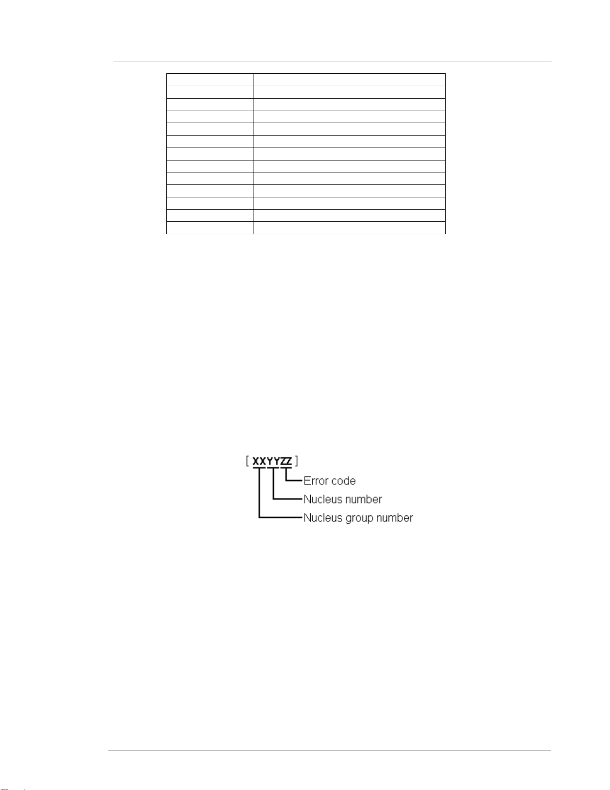
Reference : SGP_AVS_SW_ATLAS-05-04 Classification : COMPANY RESTRICTED
Version : 3.4 Project : ATLAS_DSW
Status : Draft Chapter : User Manual
Date : 2005-09-02 Section : Diagnostic Software
11 Analogue Board
12 System
13 Electronic Program Guide Board
14 PCMCIA
15 HDMI
16 Analogue Slave Processor
17 Analogue Board EEPROM
18 Video Matrix
19 Audio Matrix
20 Front End
21 Hard Disk
22 Digital Terrestrial Tuner Module
23 USB
2.2 ERROR HANDLING
Results returned from a diagnostic nucleus to the control/service PC are terminated by a 'CR'
character (included in the string length).
The result has the following layout
<number> <string> [Test OK | Erro r] @<C R>
The use of the “@” enables the Asterix system on the control PC to parse the output string of
each nucleus into a database. This system is used in the factory and automates the test
sequences needed to test each product using the Diagnostic and Service Software.
<number> is a 6-digit decimal number padded with leading zeros if its value is less than 6
digits. The first four digits identify the generating nucleus (group and nucleus); the latter two
digits indicate the error number.
Figure 2 Error-code of a diagnostic nucleus.
© Philip s Electronics N . V . 2005 Philips Digital Systems Laboratories Page 9 of 16 8
Page 25

Reference : SGP_AVS_SW_ATLAS-05-04 Classification : COMPANY RESTRICTED
Version : 3.4 Project : ATLAS_DSW
Status : Draft Chapter : User Manual
Date : 2005-09-02 Section : Diagnostic Software
2.3 COMMAND LINE INTERFACE
Via the command line interface the execution of diagnostic nuclei can be controlled.
2.3.1 Set-up of physical interface components
Hardware required:
• Control PC
• One free COM port on the Control PC
• Special cable to connect the DVD Recorder to the Control PC
The control PC must use the following port settings for the used COM port:
- 19200 bps,
data bits,
- 8
- no parity,
- 1 stop bit and
- no flow control.
The control PC is connected with a special cable (see chapter 4A.2) to the RS232 port of the
DVD Recorder. Via the same connection the ‘test pin’ will be connected to ground. Using this
pin the software can determine whether Diagnostic mode needs to be entered.
2.3.2 Activation
After power on the next text will be sent to the control PC
Factory Diagnostics and Service Software
DVD Video Recorder (Dec 13 2003, 10:55:37)
Version :258 Build :20031213_1030
Release :P1_7_b Buildtype :no
Baseline :I_P1_8_63 Variant :verum:dvdrw2_lib
DS:>
The first lines indicate that the DS has been activated and contains the version and build info of
the DS. The next line is the command line prompt (“DS:>”). The DS is now ready to receive
commands. Please note that this text will be different on your specific variant of the DVD+RW
recorder product range.
2.3.3 Usage
The commands that can be given are the numbers of the nuclei. A command must be
terminated with an <ENTER> character from the control PC. When typing commands, the
backspace key can be used to make corrections. Apart from this one can use the Up and Down
arrows to browse to previous commands.
When one enters non-supported commands, the interface returns the command line prompt.
If the command (the nucleus number) is recognised, the nucleus is executed. Result and output
of an activated (and terminated) nucleus will be sent back to the control PC.
Example in case the command is correct:
DS:> 1200
© Philip s Electronics N . V . 2005 Philips Digital Systems Laboratories Page 10 of 16 8
Page 26

Reference : SGP_AVS_SW_ATLAS-05-04 Classification : COMPANY RESTRICTED
Version : 3.4 Project : ATLAS_DSW
Status : Draft Chapter : User Manual
Date : 2005-09-02 Section : Diagnostic Software
120000: Hardware ID = 0x27
Test OK @
Example in case the result is an error (DVD+RW 2.1 example):
DS:> 1100
110002: Communication with Analogue Board fails
Error @
DS:>
2.3.4 Termination
To turn off the command line interface switch off the DVD Recorder.
2.4 END-USER/DEALER SCRIPT INTERFACE
This interface is used during execution of the script to display output and error messages.
The local display will be used to display the output and the error messages.
2.4.1 Set-up physical interface components
Hardware required:
• DVD Recorder
The DVD Recorder is tested stand-alone: no other equipment than the DVD Recorder is
needed.
2.4.2 Activation
Pressing the play-key on the keyboard of the DVD Recorder during power-on activates the
dealer script.
2.4.3 Usage
The test requires no user interaction. A number of nuclei will be run before a message is
returned indicating if there is a failure in the DVD Recorder (‘’PASS” will be indicated when the
product functions OK and “FAIL” when there has been an error during one of the tests).
During the execution of this script, a progress indicator is displayed on the display of the DVD
Recorder.
that from the command line interface this script can be started as well, by entering ‘script’
Note
on it.
2.4.4 Termination
To turn off the dealer test, the DVD Recorder must be powered down.
© Philip s Electronics N . V . 2005 Philips Digital Systems Laboratories Page 11 of 168
Page 27
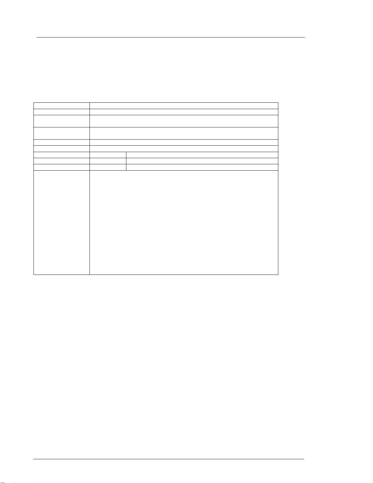
Reference : SGP_AVS_SW_ATLAS-05-04 Classification : COMPANY RESTRICTED
Version : 3.4 Project : ATLAS_DSW
Status : Draft Chapter : User Manual
Date : 2005-09-02 Section : Diagnostic Software
3 DETAILED DESCRIPTION OF A VAILABLE NUCLEI
3.1 CODEC HOST CONTROLLER (CHR)
Nucleus Name DS_CHR_DevTypeGet
Nucleus Number 100
Description Retrieves the device id , the module ids an d revisions of the Codec and returns
Technical - Determine the codec id by means of comparing version ids of the modules.
Execution Time Less than 1 second.
User Input None
Error Number Description
10000 Getting the information succeeded
10001 Wrong codec id detected
Example
them to the stdout port.
- Read the module-id registe r of every module and display it to the user.
DS:> 100
010000:
Device ID 7100
Codec ID PNX7100_C
F-BCU (0x0102) 1.0 INTC (0x011d) 1.0 PCI-XIO(0x0113) 1.0
SIF (0x013b) 1.0 EJTAG (0x0104) 0.1 S-BCU (0x0102) 1.0
BOOT (0x010a) 1.0 CONFIG (0x013f) 1.1 RESET (0x0123) 1.0
DEBUG (0x0116) 0.0 UART0 (0x0107) 0.1 UART1 (0x0107) 0.1
UART2 (0x0107) 0.1 UART3 (0x0107) 0.1 I2C0 (0x0105) 0.1
I2C1 (0x0105) 0.1 GPIO (0x013c) 1.0 SYNC (0x013a) 1.0
DISP0 (0xa015) 1.12 DISP1 (0xa00f) 1.1 OSD (0x0136) 0.1
SPU (0xa00e) 0.0 MIXER (0x0137) 1.0 DENC (0x0138) 1.0
CCIR (0x0139) 1.0 VDEC (0x0133) 0.2 PARSER (0xa00d) 0.0
DV (0xa00c) 0.0 BEI (0xa00a) 0.1 IDE (0xa009) 0.1
SGDX (0xa008) 1.0 BYTE (0xa00b) 0.1 OUTPUT (0xa003) 1.0
ACOMP (0xa000) 1.0 VFE (0xa001) 0.1 VCOMP (0xa002) 1.0
SCR (0x0000) 0.0 SIFF (0xa011) 0.1 WMD (0xa010) 0.0
AUDIO0 (0xa015) 1.12 AUDIO1 (0xa00f) 1.1 PSCAN (0xa018) 0.1
Test OK @
© Philip s Electronics N . V . 2005 Philips Digital Systems Laboratories Page 12 of 16 8
Page 28
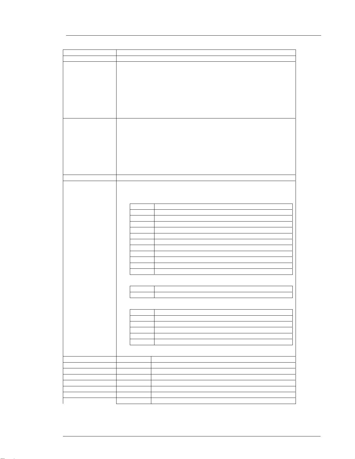
Reference : SGP_AVS_SW_ATLAS-05-04 Classification : COMPANY RESTRICTED
Version : 3.4 Project : ATLAS_DSW
Status : Draft Chapter : User Manual
Date : 2005-09-02 Section : Diagnostic Software
Nucleus Name DS_CHR_TestImageOn
Nucleus Number 101
Description Generates a test-image of a selected vid eo standard on selected video output
Technical - Validate the user input.
Execution Time 6 seconds.
User Input The user has to decide which test image , video stan dard and vid eo output mus t
Error Number Description
10100 Generating the test image succeeded.
10101 Invalid input was provided.
10102 The Codec SYNC-module cannot be initialised.
10103 The Codec MIXER-module cannot be initialised.
10104 The Codec VPP-module cannot be initialised.
10105 The Codec DENC-module cannot be initialised.
10106 The digital board hardware information is corrupt
on the digital board. When no input is given, the default values will be used (see
user input description below). Make sure to use the proper nuclei to route the
video signal on the analogue board to get the video signal to the proper output.
Note: Although a DTT has a Chrysalis C3, the codec IC may never use the
YUV functionality of the internal DENC. This is sp ecified by the hardware. The
digital boards for DTT do have a YUV- matrix. The signals from t his YUV-matrix
are not routed to the regular video output co nnector but to t he progr essive scan
output connector.
- Initialise the SYNC module.
- Initialise the DISPLAY module.
- Initialise the MIXER module.
- Initialise the DENC module.
- Set the selected video standard.
- Generate the selected test image in memory.
- Start the DISPLAY module.
- Start the MIXER module.
- Start the DENC module according to the selected test image id.
be used: < Test image i d > < Video standard > < Video output >
Test image id:
0 VERTICAL_COLOURBAR (default)
1 HORIZONTAL_COLOURBAR
2 WHITE
3 YELLOW
4 CYAN
5 GREEN
6 MAGENTA
7 RED
8 BLUE
9 BLACK
10 GRAY
11 TEST_IMAGE_FOR_PROGRESSIVE_SCAN
Video standard:
PAL Standard PAL 50 Hz (default)
NTSC Standard NTSC 60 Hz
Video output:
ALL CVBS and YC and RGB DACs are enabled (default)
CVBS CVBS DAC is enabled
YC Y and C DAC is enabled
RGB CVBS, R, G, and B DACs are enabled
YUV Y, U, and V DACs are enabled
PSCAN Progressive scan is enabled.
© Philip s Electronics N . V . 2005 Philips Digital Systems Laboratories Page 13 of 168
Page 29
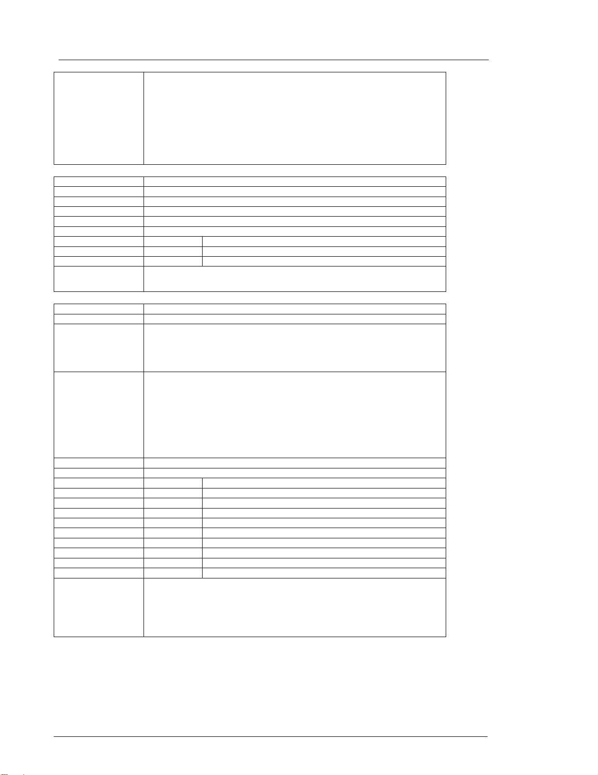
Reference : SGP_AVS_SW_ATLAS-05-04 Classification : COMPANY RESTRICTED
Version : 3.4 Project : ATLAS_DSW
Status : Draft Chapter : User Manual
Date : 2005-09-02 Section : Diagnostic Software
Example
DS:> 101
010100:
Test OK @
DS:> 101 0 pal cvbs
010100:
Test OK @
DS:> 101 4 ntsc yc
010100:
Test OK @
Nucleus Name
Nucleus Number 102
Description Switches the test-image off.
Technical - Stop the DENC module.
Execution Time Less than 1 second.
User Input None
Error Number Description
10200 Stopping the test image generation succeeded
10201 The Codec DENC-module failed.
Example
DS_CHR_TestImageOff
DS:> 102
010200:
Test OK @
Nucleus Name DS_CHR_SineOn
Nucleus Number 103
Description Generate an audio sine signal on the audio output of the digital board.
Note: Left channel 6kHz, right channel 12 kHz sine. Make sure to route the
signal first.
When ‘SPDIF’ is entered as a parameter, the SPDIF path will be activated
correctly to contain the sine wave.
Technical - De-mute the analogue board
- Set fifo parameters for audio
- Set the volume
- Set the I2S outputs and configuration paths
- Set the decoder mode
- Configure the audio decoder
- Put the AC3 audio in the fifo
- Send ‘prepare’ command to the audio decoder
- Send ‘play’ command to the audio decoder
Execution Time Less than 1 second
User Input None or ‘SPDIF’
Error Number Description
10300 The sine signal was successfully generated
10301 The analogue board could not be de-muted
10302 The audio decoder did not initialise
10303 The dsp2 (DUET) of the audio decoder did not configure
10304 The dsp1 (PALM) of the audio decoder did not configure
10305 There was a delay-error before starting
10306 Wrong input was given to the decoder function
10307 Wrong input was given to the decoder function @@@@@
10308 The audio decoder did not get into the ‘prepared’ state
Example
DS:> 103
010300:
Test OK @
DS:> 103 spdif
010300:
Test OK @
© Philip s Electronics N . V . 2005 Philips Digital Systems Laboratories Page 14 of 16 8
Page 30
Reference : SGP_AVS_SW_ATLAS-05-04 Classification : COMPANY RESTRICTED
Version : 3.4 Project : ATLAS_DSW
Status : Draft Chapter : User Manual
Date : 2005-09-02 Section : Diagnostic Software
Nucleus Name DS_CHR_SineOff
Nucleus Number 104
Description Stop generating the audio sine signal
Technical - Reset the audio block of the Codec
Execution Time Less than 1 second.
User Input None
Error Number Description
10400 Switching off the audio sine signal succeeded
10401 Failed to reset the audio decoder
Example
DS:> 104
010400:
Test OK @
Nucleus Name
Nucleus Number 105
Description Generate an audio sine signal on the audio output of the digital board for 4
Technical - Call the DS_CHR_SineOn nucleus
Execution Time 4 seconds
User Input None
Error Number Description
10500 The sine signal burst was successfully generated
10501 The delay did not succeed during the burst
10502 The audio sine could not be generated
Example
DS_CHR_SineBurst
seconds.
Note: Left channel 6kHz, right channel 12 kHz sine with some known hick-ups
- Delay for 4 seconds
- Call the DS_CHR_SineOff nucleus
DS:> 105
010500:
Test OK @
Nucleus Name
Nucleus Number 106
Description Mute the audio outputs of the digital board
Technical - Send the ‘Mute’ command to the audio decoder
Execution Time Less than 1 second.
User Input “PIO” to just us e the PIO pin mute. When muting using this, also d e-mute using
Error Number Description
10600 Muting the audio succeeded
10601 Muting the audio through the PIO-pin failed
Example
DS_CHR_MuteOn
- Activate the ‘audio mute’ PIO pin
this as this works ‘paired’.
DS:> 106
010600:
Test OK @
DS:> 106 PIO
010600:
Test OK @
© Philip s Electronics N . V . 2005 Philips Digital Systems Laboratories Page 15 of 168
Page 31

Reference : SGP_AVS_SW_ATLAS-05-04 Classification : COMPANY RESTRICTED
Version : 3.4 Project : ATLAS_DSW
Status : Draft Chapter : User Manual
Date : 2005-09-02 Section : Diagnostic Software
Nucleus Name DS_CHR_MuteOff
Nucleus Number 107
Description De-mute the audio outputs of the digital board
Technical - Send the ‘DeMute’ command to the audio decoder
- Deactivate the ‘audio mute’ PIO pin
Execution Time “PIO” to just use the PIO pin de-mut e. Only de-mute using this when you muted
using the PIO parameter, as this works ‘’paired.
User Input None
Error Number Description
10700 De-muting the audio succeeded
10701 De-muting the audio through the PIO-pin failed
Example
DS:> 107
010700:
Test OK @
DS:> 107 PIO
010700:
Test OK @
Nucleus Name DS_CHR_DvLedOn
Nucleus Number 108
Description Check the connection to the DV-LED on the digital board by switching it on
Technical - Write to the PIO pin to light the DV LED
Execution Time Less than 1 second.
User Input None
Error Number Description
10800 Switching the DV-LED on succeeded
10801 Switching the DV-LED on failed
Example
DS:> 108
010800:
Test OK @
Nucleus Name
Nucleus Number 109
Description Switch off the DV-LED on the digital board
Technical - Write to the PIO pin to s witch off the DV LED
Execution Time Less than 1 second.
User Input None
Error Number Description
10900 Switching the DV-LED off succeeded
10901 Switching the DV-LED off failed
Example
DS_CHR_DvLedOff
DS:> 109
010900:
Test OK @
Nucleus Name DS_CHR_MacroVisionOn
Nucleus Number 110
Description Turn on MacroVision.
Technical - Set some registers of the DENC module in the Codec.
Execution Time Less than 1 second.
User Input None
Error Number Description
11000 Turning on MacroVision succeeded
11001 Turning on MacroVision failed
Example
DS:> 110
011000:
Test OK @
© Philip s Electronics N . V . 2005 Philips Digital Systems Laboratories Page 16 of 16 8
Page 32

Reference : SGP_AVS_SW_ATLAS-05-04 Classification : COMPANY RESTRICTED
Version : 3.4 Project : ATLAS_DSW
Status : Draft Chapter : User Manual
Date : 2005-09-02 Section : Diagnostic Software
Nucleus Name DS_CHR_MacroVisionOff
Nucleus Number 111
Description Turn off MacroVision.
Technical - Set some registers of the DENC module in the Codec.
Execution Time Less than 1 second.
User Input None
Error Number Description
11100 Turning off MacroVision succeeded
11101 Turning off MacroVision failed
Example
DS:> 111
011100:
Test OK @
Nucleus Name DS_CHR_Peek
Nucleus Number 112
Description Peek a value on a specified address
Technical - Check the user input
- Read out the address specified
- Check whether the address to be read is align e d on 4 bytes
Execution Time Less than 1 second.
User Input The address to peek on
Error Number Description
11200 Peeking on the specified address succeeded
11201 Peeking on the specified address failed, wrong user input
11202 Peeking on the specified address failed due to misalignment
Example
DS:> 112 0xa0700000
011200: Value read = 0x000001BD
Test OK @
Nucleus Name
Nucleus Number 113
Description Poke a value on a specified address
Technical - Check the user input
Execution Time Less than 1 second.
User Input The address to poke and the valu e: <ad dress><value>
Error Number Description
11300 Poking the specified address succeeded
11301 Poking the specified address failed, wrong user input
11302 Poking the specified address failed due to misal ignment
Example
DS_CHR_Poke
- Change the value on the address specified
- Check whether the address to be modified is aligned on 4 bytes
DS:> 113 0xa0700000 0xaabbccdd
011300:
Test OK @
Nucleus Name DS_CHR_INT_PICInterrupts
Nucleus Number 114
Description Test all interrupts of the priority interrupt controller
Technical - Install interrupt handlers
- Generate interrupts
- Test whether all interrupts were received
Execution Time Less than 1 second.
User Input Error Number Description
11400 Testing all the PIC interrupts succeeded
11401 Testing all the PIC interrupts failed
Example
DS:> 114
011400:
Test OK @
© Philip s Electronics N . V . 2005 Philips Digital Systems Laboratories Page 17 of 168
Page 33

Reference : SGP_AVS_SW_ATLAS-05-04 Classification : COMPANY RESTRICTED
Version : 3.4 Project : ATLAS_DSW
Status : Draft Chapter : User Manual
Date : 2005-09-02 Section : Diagnostic Software
Nucleus Name DS_CHR_DMA_TestDMA
Nucleus Number 115
Description Test the memory to memory DMA transfer
Technical - Create a block with known data in memory
Execution Time Less than 2 seconds.
User Input Error Number Description
11500 The testing of the DMAs succeeded
11501 The initialisation of the DMAs failed for one or more DMA
11502 One or more DMAs failed the test
Example
- Copy this block to the consecutive area using 3 different DMAs
- Check whether all DMAs transferred the data properly
DS:> 115
011500:
Test OK @
© Philip s Electronics N . V . 2005 Philips Digital Systems Laboratories Page 18 of 16 8
Page 34

Reference : SGP_AVS_SW_ATLAS-05-04 Classification : COMPANY RESTRICTED
Version : 3.4 Project : ATLAS_DSW
Status : Draft Chapter : User Manual
Date : 2005-09-02 Section : Diagnostic Software
3.2 BOOT EEPROM (BROM)
Nucleus Name DS_BROM_Communication
Nucleus Number 200
Description Check the com munication between th e IIC cont roller of t he Codec a nd the bo ot
Technical - Initialise IIC
Execution Time Less than 1 second.
User Input None
Error Number Description
20000 The data is properly read so the communication is OK
20001 The IIC bus was not accessible
20002 There was a timeout reading the device
20003 The IIC acknowledge was not received
20004 An IIC-bus error occurred
20005 The IIC bus initialisation failed
20006 An unexpected IIC error occurred
Example
Nucleus Name
Nucleus Number 201
Description Check whether the Boot EEPROM can be written to and read from
Technical - Initialise IIC
Execution Time Less than 1 second.
User Input None
Error Number Description
20100 The write-read test succeeded
20101 The write-read test failed
20102 An IIC-bus error occurred
20103 There was a timeout reading the device
20104 The IIC bus was not accessible
20105 The IIC acknowledge was not received
20106 Got unknown IIC bus error
20107 The IIC bus initialisation failed
Example
EEPROM
- Read something from the EEPROM
DS:> 200
020000:
Test OK @
DS_BROM_WriteRead
- Write something to the EEPROM
- Read from the same location and check whether it is the same as written
DS:> 201
020100:
Test OK @
© Philip s Electronics N . V . 2005 Philips Digital Systems Laboratories Page 19 of 168
Page 35

Reference : SGP_AVS_SW_ATLAS-05-04 Classification : COMPANY RESTRICTED
Version : 3.4 Project : ATLAS_DSW
Status : Draft Chapter : User Manual
Date : 2005-09-02 Section : Diagnostic Software
3.3 NON VOLATILE RAM (NVRAM)
Nucleus Name DS_NVRAM_Communication
Nucleus Number 300
Description Check the communication between the IIC controller of the Codec and the
Technical - Initialise IIC
Important note: This nucleus only checks the physical connection between the Codec and IIC
Execution Time Less than 1 second.
User Input None
Error Number Description
30000 Something is properly read so the communication is OK
30001 The IIC bus was not accessible
30002 There was a timeout reading the device
30003 The IIC acknowledge was not received
30004 The communication with the device failed
30005 The IIC bus initialisation failed
Example
Nucleus Name DS_NVRAM_WriteRead
Nucleus Number 301
Description Check whether the EEPROM can be written to and read from
Technical - Initialise IIC
Execution Time Less than 1 second
User Input None
Error Number Description
30100 The write-read test succeeded
30101 The IIC bus could not be initialised
30102 There was an NVRAM IO error
30103 The value could not be read back from the NVRAM
Example
NVRAM EEPROM
- Read from a location in the NVRAM EEPROM device
EEPROM. If no EEPROM is mounted this test will fail. However other NVRAM
nuclei might still work because the software will store NVM data into flash
memory
DS:> 300
030000:
Test OK @
- If no IIC EEPROM was found then initialise flash memory to use NVM
pages
- Backup data from location to modify
- Write to location and read it back again
- Write back the backed up data to the location to leave the NVRAM as
found
DS:> 301
030100:
Test OK @
© Philip s Electronics N . V . 2005 Philips Digital Systems Laboratories Page 20 of 16 8
Page 36

Reference : SGP_AVS_SW_ATLAS-05-04 Classification : COMPANY RESTRICTED
Version : 3.4 Project : ATLAS_DSW
Status : Draft Chapter : User Manual
Date : 2005-09-02 Section : Diagnostic Software
Nucleus Name DS_NVRAM_Clear
Nucleus Number 302
Description Make the EEPROM empty, containing all zeroes.
Technical - Initialise IIC
Important note:
Execution Time 16 seconds
User Input None
Error Number Description
30200 The clearing of the NVRAM succeeded
30201 There was an IIC error
30202 Clearing the NVRAM failed
Example
- If no IIC EEPROM was found then initialise flash memory to use NVM
pages
- Read the DVID and diversity string from NVM (either EEPROM or Flash)
- Create a memory block filled with zeroes
- Write this block to the NVRAM (either EEPROM or Flash)
- Write back the Read the DVID and diversity string to NVM (either
EEPROM or Flash)
The Hardware Diversity Information and unique identification number
(IEE1394-specific) of the Digital Video processing part is NOT cleared b y this
nucleus!
DS:> 302
030200:
Test OK @
Nucleus Name DS_NVRAM_Modify
Nucleus Number 303
Description Modifies one or more loca tions in NVRAM and updates the checksum of the
Technical - Initialise IIC
Execution Time Less than 1 second
User Input 1. The location that mus t be modif ie d
Error Number Description
30300 Modifying the NVRAM contents succeeded
30301 Unable to initialise NVM
30302 Modifying the NVRAM contents failed
30303 length out of range
30304 unable to decode length
30305 offset out of range
30306 unable to decode offset
30307 unknown location specified
30308 no location is specified
30309 number of values incorrect
30310 There was an IIC error
Example
section modified
- If no IIC EEPROM was found then initialise flash memory to use NVM
pages
- Decode user input
- Modify the NVRAM as indicated
- Validate the NVRAM by calculating the checksum and storing it
i.e. "ALL" "BOOT" "DIAGNOSTICS" "DOWNLOAD" "CONFIG"
"RECORDER" or no string if an offset from the base address of the
NVRAM is required
2. The offset and data which to put on the selected location
<offset> <length> <data>
DS:> 303 DIAGNOSTICS 5 1 0x5a
030300: Section is modified successfully
Test OK @
© Philip s Electronics N . V . 2005 Philips Digital Systems Laboratories Page 21 of 168
Page 37

Reference : SGP_AVS_SW_ATLAS-05-04 Classification : COMPANY RESTRICTED
Version : 3.4 Project : ATLAS_DSW
Status : Draft Chapter : User Manual
Date : 2005-09-02 Section : Diagnostic Software
Nucleus Name DS_NVRAM_Read
Nucleus Number 304
Description Read out one or more locations in the NVRAM
Technical - Initialise IIC
Execution Time Less than 1 second
User Input 1. The location which mus t be read
Error Number Description
30400 Value read
30401 Unable to initialise NVM
30402 Reading the NVRAM contents failed
30403 Length out of range
30404 Unable to decode length
30405 Offset out of range
30406 Unable to decode offset
30407 Unknown location specified
30408 No location is specified
Example
- If no IIC EEPROM was found then initialise flash memory to use NVM
pages
- Decode user input
- Read from the NVRAM and return this info to the user
i.e. "ALL" "BOOT" "DIAGNOSTICS" "DOWNLOAD" "CONFIG"
"RECORDER" or no string if an offset from the base address of the
NVRAM is required
2. The offset and number of bytes to read
<offset> <length>
304 DIAGNOSTICS 0 6
030400: Value read = 0x00 0x00 0x00 0x00 0x00 0x5A
Test OK @
© Philip s Electronics N . V . 2005 Philips Digital Systems Laboratories Page 22 of 16 8
Page 38

Reference : SGP_AVS_SW_ATLAS-05-04 Classification : COMPANY RESTRICTED
Version : 3.4 Project : ATLAS_DSW
Status : Draft Chapter : User Manual
Date : 2005-09-02 Section : Diagnostic Software
3.4 SDRAM (SDRAM)
Nucleus Name DS_SDRAM_WriteRead
Nucleus Number 400
Description Check all data lines, address lines and memory locations of the SDRAM
Technical - Test the data bus
Execution Time 11 seconds for 32 Mb
User Input None
Error Number Description
40000 The write-read test succeeded
40001 The data bus contains an error
40002 The address bus contains an error
40003 The SDRAM itself contains an error
Example
Nucleus Name
Nucleus Number 401
Description Check all data lines and address lines of the SDRAM
Technical - Test the data bus
Execution Time Less than 1 second
User Input None
Error Number Description
40100 The write-read test succeeded
40101 The data bus contains an error
40102 The address bus contains an error
Example
Nucleus Name DS_SDRAM_Write
Nucleus Number 402
Description Write to a specific un-cached memory address
Technical - Decode the user input and check its ranges and alignment on 4 bytes
Execution Time Less than 1 second
User Input 1. The location that mus t be modif ie d
Error Number Description
40200 Writing to the SDRAM succeeded
40201 Writing to the SDRAM failed; Wrong user input
40202 Address is not dividable by 4
Example
- Test the address bus
- Test the integrity of the device itself (memory locations)
23 seconds for 64 Mb
DS:> 400
040000:
Test OK @
DS_SDRAM_WriteReadFast
- Test the address bus
DS:> 401
040100:
Test OK @
- Write the data to the SDRAM
(SDRAM starts at address 0xA0000000)
2. The value to put on the selected location
DS:> 402 0xa1000010 0xad112222
040200:
Test OK @
© Philip s Electronics N . V . 2005 Philips Digital Systems Laboratories Page 23 of 168
Page 39

Reference : SGP_AVS_SW_ATLAS-05-04 Classification : COMPANY RESTRICTED
Version : 3.4 Project : ATLAS_DSW
Status : Draft Chapter : User Manual
Date : 2005-09-02 Section : Diagnostic Software
Nucleus Name DS_SDRAM_Read
Nucleus Number 403
Description Read from a specific un-cached memory address
Technical - Decode the user input and check the ranges
Execution Time Less than 1 second
User Input The location from which the data must be read
Error Number Description
40300 Reading from the SDRAM succeeded
40301 Reading from the SDRAM failed; Wrong user input
40302 Address is not dividable by 4
Example
- Read from the SDRAM and return this info to the user
(SDRAM starts at address 0xA0000000)
DS:> 403 0xa1000010
040300: Value read = 0xAD112222
Test OK @
Nucleus Name DS_SDRAM_DmaWriteRead
Nucleus Number 404
Description Write a pattern to the entire SDRAM using DMA and check the data
Technical - Check if the Stack pointer is not in the write range
Execution Time 24 seconds
User Input None.
Error Number Description
40400 Writing to the SDRAM succeeded
40401 Stack area definition ERROR!
40402 DMA controller could not be initialised.
40403 Not all data was transferred correctly
Example
- Clear a 64kb block and then fill it with a pattern
- Initialise the DMA controller and writ e the dat a to th e SDRAM
- Then check if all the data was written correctly (except descriptor tables)
- Repeat the process 4 times with 4 different patterns
DS:> 404
040400:
Test OK @
© Philip s Electronics N . V . 2005 Philips Digital Systems Laboratories Page 24 of 16 8
Page 40

Reference : SGP_AVS_SW_ATLAS-05-04 Classification : COMPANY RESTRICTED
Version : 3.4 Project : ATLAS_DSW
Status : Draft Chapter : User Manual
Date : 2005-09-02 Section : Diagnostic Software
3.5 FLASH (FLASH)
Nucleus Name DS_FLASH_DevTypeGet
Nucleus Number 500
Description Get the device (revision) type information of the FLASH ICs. (type,
Technical - Set the timing for the flash writing
Execution Time Less than 1 second
User Input None
Error Number Description
50000 Getting the information from the FLASH succeeded
50001 Getting the information from the FLASH failed
Example
Nucleus Name DS_FLASH_WriteRead
Nucleus Number 501
Description Check whether the FLASH can be written to and read from
Technical - Find the test segment in flash
Execution Time Less than 1 second.
User Input None
Error Number Description
50100 The FLASH write-read test succeeded
50101 The test segment could not be found
50102 All bits in the TEST region are filled with 0 (region exhausted)
50103 The Write Read test failed
50104 The Write Failed
Example
Nucleus Name
Nucleus Number 502
Description Read from a specific memory address in FLASH
Technical - Deco de the user input and check th e ranges and whether the address is
Execution Time Less than 1 second.
User Input The location from which data must be read
Error Number Description
50200 Reading the FLASH succeeded
50201 Reading the FLASH failed; Wrong user input
50202 Address is not dividable by 4
Example
manufacturer, device ID and size)
- Write a command sequence to determine device type information
- Return the information to th e user
DS:> 500
050000: Found FLASH memory:
NOR AMD 29DL640G 8MB,NOR AMD 29DL640G 8MB
Test OK @
- Read the data into SDRAM
- Modify the data
- Write this data from SDRAM to FLASH and verify it by reading back again
DS:> 501
050100:
Test OK @
DS_FLASH_Read
aligned on 4 bytes
- Read the data and return this to the user
(FLASH starts at address 0xB8000000)
DS:> 502 0xb8000000
050200: Value read = 0x3C08A000
Test OK @
© Philip s Electronics N . V . 2005 Philips Digital Systems Laboratories Page 25 of 168
Page 41

Reference : SGP_AVS_SW_ATLAS-05-04 Classification : COMPANY RESTRICTED
Version : 3.4 Project : ATLAS_DSW
Status : Draft Chapter : User Manual
Date : 2005-09-02 Section : Diagnostic Software
Nucleus Name DS_FLASH_ChecksumProgram
Nucleus Number 503
Description Check the checksum of the application partitions by recalculating and
comparing partition checksums
Technical - Determine the number of segments
- Find the application in each segment and det e rmin e it s check su m
- Check whether the checksums stored match the newly calculated
Execution Time 6 seconds
User Input None
Error Number Description
50300 The checksum is valid, the test succeeded
50301 The checksum is invalid
Example
DS:> 503
050300:
BootCode checksum is: 0xBABE5B6F, which is correct
Diagnostics checksum is: 0xBABEBAFF, which is correct
Download checksum is: 0xBABEEDBF, which is correct
Application checksum is: 0xBABE8EEC, which is correct
Test OK @
Nucleus Name DS_FLASH_CalculateChecksum
Nucleus Number 504
Description Calculate the checksum over all memory addresses. Used to check entire
FLASH contents
Technical - Run the checksum calculation algorithm on all flash memory addresses
Execution Time 6 seconds
User Input None
Error Number Description
50400 Calculating the checksum over all addresses succeeded
Example
DS:> 504
050400: The Checksum = 0xBABE30A4
Test OK @
Nucleus Name DS_FLASH_CalculateChecksumFast
Nucleus Number 505
Description Calculate a checksum over a selected number of address locations
Technical - Run the checksum calculation algorithm on a sele cted number of flash
memory addresses
Execution Time 6 seconds
User Input None
Error Number Description
50500 Calculating the checksum over selected addresses succeeded
Example
DS:> 505
050500: The Checksum = 0xBABEB064
Test OK @
© Philip s Electronics N . V . 2005 Philips Digital Systems Laboratories Page 26 of 16 8
Page 42

Reference : SGP_AVS_SW_ATLAS-05-04 Classification : COMPANY RESTRICTED
Version : 3.4 Project : ATLAS_DSW
Status : Draft Chapter : User Manual
Date : 2005-09-02 Section : Diagnostic Software
3.6 VIDEO INPUT PROCESSOR (VIP)
Nucleus Name DS_VIP_DevTypeGet
Nucleus Number 600
Description Get the device (revision) type information of the VIP IC
Technical - Initialise IIC
Execution Time Less than 1 second
User Input None
Error Number Description
60000 Getting the information from the VIP succeeded
60001 The IIC bus initialisation failed
60002 The was an error getting the information from the VIP
60003 Type not according to type stored in HW diversit y string
Example
Nucleus Name DS_VIP_Communication
Nucleus Number 601
Description Check the co mmunication betwee n the IIC control ler of the Codec and the VIP
Technical - Initialise IIC
Execution Time Less than 1 second
User Input None
Error Number Description
60100 Communicating with the VIP succeede d
60101 The IIC bus was not accessible
60102 There was a timeout reading the device
60103 The IIC acknowledge was not received
60104 The communication with the device failed
60105 The IIC bus initialisation failed
Example
Nucleus Name DS_VIP_ClockOutputOn
Nucleus Number 602
Description Switch the clock output on
Technical - Initialise IIC
Execution Time Less than 1 second
User Input None
Error Number Description
60200 Switching the clock output on succeeded
60201 Switching the clock output on failed
Example
- Read out the device (revision) type information of the VIP IC
DS:> 600
060000: Found SAA7118
Test OK @
IC
- Read data from a location in the VIP
DS:> 601
060100:
Test OK @
- Set the clock output through IIC
DS:> 602
060200:
Test OK @
© Philip s Electronics N . V . 2005 Philips Digital Systems Laboratories Page 27 of 168
Page 43

Reference : SGP_AVS_SW_ATLAS-05-04 Classification : COMPANY RESTRICTED
Version : 3.4 Project : ATLAS_DSW
Status : Draft Chapter : User Manual
Date : 2005-09-02 Section : Diagnostic Software
Nucleus Name DS_VIP_ClockOutputOff
Nucleus Number 603
Description Switch the clock output off
Technical - Initialise IIC
Execution Time Less than 1 second
User Input None
Error Number Description
60300 Switching the clock output off succeeded
60301 Switching the clock output off failed
Example
- Reset the clock output through IIC
DS:> 603
060300:
Test OK @
© Philip s Electronics N . V . 2005 Philips Digital Systems Laboratories Page 28 of 16 8
Page 44

Reference : SGP_AVS_SW_ATLAS-05-04 Classification : COMPANY RESTRICTED
Version : 3.4 Project : ATLAS_DSW
Status : Draft Chapter : User Manual
Date : 2005-09-02 Section : Diagnostic Software
Nucleus Name DS_VIP_SelectInput
Nucleus Number 604
Description Select an input video path to be s witched to the analogue outp ut pin (AOUT) of
Technical - Check the user input
Execution Time Less than 1 second
User Input The input to select, see table below.
Error Number Description
the VIP
- Initialise IIC
- Read out the VIP id
- Write the set of registers required for the input specified
Available channels for input of the 7118 and their description:
Channel number Description
1 CVBS_Y_IN_A
2 CVBS_OUT_B
3 CVBS_Y_IN_B
4 CVBS_Y_IN_C
6 C_IN
8 G_IN
9 Y_IN
13 B_IN
14 U_IN
18 R_IN
19 V_IN
Available channels for input of the 7115 and their description:
Channel number Description
1 CVBS_Y_IN_B
2 CVBS_OUT_B_VIP
4 C_IN_VIP
7 CVBS_Y_IN_B
Available channels for input of the 7119 and their descrip tio n:
Channel number Description
1 Y / CVBS
3 CVBS
4 Y3
6 C / CVBS
8 G
9 Y
12 Y2
13 B
14 U
17 C
18 R
19 V
Available channels for input of the 7173 and their description:
Channel number Description
1 CVBS_TUNER_IN
2 CVBS_REAR_IN
3 CVBS_FRONT_IN
4 C_REAR_IN
5 Y_REAR_IN
6 Y_FRONT_IN
7 C_FRONT_IN
8 AL_REAR_IN
9 AL_FRONT_IN
10 AR_FRONT_IN
11 AR_REAR_IN
12 SIF_TUNER_IN
© Philip s Electronics N . V . 2005 Philips Digital Systems Laboratories Page 29 of 168
Page 45

Reference : SGP_AVS_SW_ATLAS-05-04 Classification : COMPANY RESTRICTED
Version : 3.4 Project : ATLAS_DSW
Status : Draft Chapter : User Manual
Date : 2005-09-02 Section : Diagnostic Software
60400 Selecting the input of the VIP succeeded
60401 The user provided wrong input
60402 The VIP was not accessible
60403 An unsupported VIP was found
Example
DS:> 604 1
060400:
Test OK @
© Philip s Electronics N . V . 2005 Philips Digital Systems Laboratories Page 30 of 16 8
Page 46

Reference : SGP_AVS_SW_ATLAS-05-04 Classification : COMPANY RESTRICTED
Version : 3.4 Project : ATLAS_DSW
Status : Draft Chapter : User Manual
Date : 2005-09-02 Section : Diagnostic Software
3.7 DIGITAL VIDEO INPUT OUTPUT CIRCUIT (DVIO)
Nucleus Name DS_DVIO_LinkDevTypeGet
Nucleus Number 700
Description Get the device (revision) type information of the 1394 Link layer IC
Technical - Initialise the PIO pins on the Codec
Execution Time Less than 1 second
User Input None
Error Number Description
70000 Getting the information from the link layer IC succeeded
70001 Getting the information from the link layer IC failed
70002 Type not according to type stored in HW diversit y string
Example
Nucleus Name
Nucleus Number 701
Description Get the device (revision) type information of the 1394 Physical layer IC
Technical - Initialise the PIO pins of the Codec
Execution Time Less than 1 second
User Input None
Error Number Description
70100 Getting the information from the physical layer IC succeeded
70101 The physical layer IC was not accessible
70102 Getting the information from the physical la ye r IC faile d
70103 Type not according to type stored in HW diversit y
Example
Nucleus Name DS_DVIO_LinkCommunication
Nucleus Number 702
Description Check the access ibility of the 1394 L ink layer IC by writing to and re ading from
Technical - Initialise the PIO pins of the Codec
Execution Time Less than 1 second
User Input None
Error Number Description
70200 Communicating with the link layer IC succee ded
70201 Communicating with the link layer IC failed
70202 Result of nucleus not according to HW diversity string
Example
- Read out the ID register
DS:> 700
070000: Device type of the link layer IC: ffc00301
Test OK @
DS_DVIO_PhyDevTypeGet
- Write the PHY-access register in the Link chip to indicate phy read access
- Wait until the link chip has obtained the val u e f rom the phy-chip
- Read this out and filter the data to be returned to the user
DS:> 701
070100: Physical layer IC: VendorID: 0x006037, ProductID: 0x412801
Test OK @
a specific address
- Write a pattern to the CYCTM register of the link chip
- Read back and verify the pattern
DS:> 702
070200:
Test OK @
© Philip s Electronics N . V . 2005 Philips Digital Systems Laboratories Page 31 of 168
Page 47

Reference : SGP_AVS_SW_ATLAS-05-04 Classification : COMPANY RESTRICTED
Version : 3.4 Project : ATLAS_DSW
Status : Draft Chapter : User Manual
Date : 2005-09-02 Section : Diagnostic Software
Nucleus Name DS_DVIO_PhyCommunication
Nucleus Number 703
Description Check the accessibility of the 1394 Ph ysical layer IC by writing to and reading
Technical - Initialise the PIO pins of the Codec
Execution Time Less than 1 second
User Input None
Error Number Description
70300 Communicating with the physical layer IC succeeded
70301 The physical layer IC was not accessible
70302 Communicating with the physical layer IC failed
70303 Result of nucleus not according to HW diversity string
Example
from a specific address
- Initialise IIC
- Write the data to be written to the PHY-chip to the link chip first
- Wait until the link chip indicates that the data has been written to the PHY
- Write the PHY-access register in the Link chip to indicate PHY read access
- Wait until the link chip has obtained the value from the PHY-chip
- Test whether the value read back equals the one pr evi ous l y wri tten
DS:> 703
070300:
Test OK @
Nucleus Name DS_DVIO_Routing
Nucleus Number 704
Description Route a DV stream containing an audio and video signal through the physical
Technical - Initialise the DMA to transfer 5 frames PAL/NTSC
Execution Time 6-10 seconds (6 when OK, 10 when no stream o r error)
User Input None
Error Number Description
70400 Routing the signals succeeded
70401 The 1394 link chip could not be initialised pro perly
70402 There was a syntax error in the DV stream
70403 DMA could not copy DV stream to memory. Stream connected?
70404 DMA not working properly
Example
and link layer ICs to the Codec. This test works for both NTSC and PAL.
- Initialise the DV de-multiplexer
- Initialise the 1394 interface and start reception of the DV stream
- Check whether the stream was copied to memory properly by the byte
input interface (port to memory type DMA)
DS:> 704
070400:
Test OK @
Nucleus Name
Nucleus Number 705
Description Check whether a DV node can be detected b y the hard ware. Th is tes t wor ks for
Technical - Initialise the 1394 interface
Execution Time 3 or 5 seconds (3 when OK, 5 when no stream or error)
User Input None
Error Number Description
70500 The node was detected OK
70501 The 1394 link chip could not be initialised pro perly
70502 Unable to write to 1394 PHY chip
70503 Unable to read from 1394 PHY chip
70504 No node was detected
Example
DS_DVIO_DetectNode
both NTSC and PAL.
- Detect whether a node is in range
DS:> 705
070500:
Test OK @
© Philip s Electronics N . V . 2005 Philips Digital Systems Laboratories Page 32 of 16 8
Page 48

Reference : SGP_AVS_SW_ATLAS-05-04 Classification : COMPANY RESTRICTED
Version : 3.4 Project : ATLAS_DSW
Status : Draft Chapter : User Manual
Date : 2005-09-02 Section : Diagnostic Software
Nucleus Name DS_DVIO_DetectStream
Nucleus Number 706
Description Check whether a DV stream can be de tected by the hardware. This test wo rks
Technical - Initialise the 1394 interface
Execution Time 3 or 5 seconds (3 when OK, 5 when no stream or error)
User Input None
Error Number Description
70600 The stream was detected
70601 The 1394 link chip could not be initialised pro perly
70602 No stream detected
Example
for both NTSC and PAL.
- Start receiving the stream
- Detect whether the stream is OK
DS:> 706
070600:
Test OK @
© Philip s Electronics N . V . 2005 Philips Digital Systems Laboratories Page 33 of 168
Page 49
Reference : SGP_AVS_SW_ATLAS-05-04 Classification : COMPANY RESTRICTED
Version : 3.4 Project : ATLAS_DSW
Status : Draft Chapter : User Manual
Date : 2005-09-02 Section : Diagnostic Software
3.8 PROGRESSIVE SCAN CIRCUIT (PSCAN)
Nucleus Name
Nucleus Number 800
Description Get the device (revision) type information of the progressive scan ic.
Technical - Initialise the progressive scan ic.
Execution Time 1 second
User Input None
Error Number Description
80000 Everything went well.
80001 The communication with the device failed
80002 No chip was expected
Example
Nucleus Name
Nucleus Number 801
Description Check the communication between the IIC controller of the Codec and the
Technical - Initialise IIC
Execution Time Less than 1 second
User Input None
Error Number Description
80100 Communicating with the progressive scan ic succeeded
80101 The IIC bus was not accessible
80102 There was a timeout reading the device
80103 The IIC acknowledge was not received
80104 Communicating with the progressive scan ic failed
80105 The initialisation of the IIC bus failed
80106 The read data is not the same as the written data
80107 No chip was expected
Example
Nucleus Name DS_PSCAN_TestImageOn
Nucleus Number 802
Description Generate the test images that are present on the progressive scan IC.
Technical - Determine whether the user wanted a HATCH or a FRAME image pattern
Execution Time Less than 1 second
DS_PSCAN_DevTypeGet
- Try to read the version register of the progressive scan ic.
DS:> 800
080000:
Chip name : 2300
Chip version : 1
Test OK @
DS:> 800
080000:
Chip name : ADV7196
Test OK @
DS:> 800
080000:
Chip name : ADV7302
Test OK @
DS_PSCAN_Communication
progressive scan IC
- Write data to a register of the progressive scan ic through IIC
DS:> 801
080100:
Test OK @
- Initialise the PIO pins of the Codec
- Initialise IIC
- Reset the DENC
- Enable the 27Mhz clock
- Send all settings for the pattern to the DENC through IIC
© Philip s Electronics N . V . 2005 Philips Digital Systems Laboratories Page 34 of 16 8
Page 50

Reference : SGP_AVS_SW_ATLAS-05-04 Classification : COMPANY RESTRICTED
Version : 3.4 Project : ATLAS_DSW
Status : Draft Chapter : User Manual
Date : 2005-09-02 Section : Diagnostic Software
User Input In case of ADV7196:
Error Number Description
80200 The generation of the test image succeeded
80201 Unable to initialise PSCAN IC
80202 Unable to reset DENC
80203 Unable to generate image
80204 No chip was expected
Example
When no input is given “HATCH” is the default
-“HATCH”
-“FRAME”
Remark:
“HATCH” is a crosshatch test pattern (horizontal and vertical white lines are
displayed against a black background)
“FRAME” is a uniform coloured frame/field test pattern (default white).
In case of FLI2300: Nothing.
DS:> 802 HATCH
080200:
Test OK @
Nucleus Name
Nucleus Number 803
Description Switch off the generated test image
Technical - Initialise IIC
Execution Time Less than 1 second
User Input None
Error Number Description
80300 Turning off the test image succeeded
80301 Unable to initialise PSCAN IC
80302 IIC Error during writing PSCAN IC
80303 No chip was expected
Example
DS_PSCAN_TestImageOff
- Send the default DENC settings to the DENC through IIC
DS:> 803
080300:
Test OK @
Nucleus Name DS_PSCAN_TestImageColourSettingsSet
Nucleus Number 804
Description Set the colour of the hatch- or the frame- field to a different value than the
default white
Technical - Determine which colour must be set.
- Initialise IIC.
- Enable 27 MHz PSCAN Clock.
- Send all settings to the DENC through IIC.
Execution Time Less than 1 second.
User Input A colour string of one of the nex t non-case sensitive strings ( WHITE, BLACK,
RED, GREEN, BLUE, YELLOW, CYAN, MAGENTA ) or Y Cr Cb (hexa-)
decimal values.
Error Number Description
80400 Setting the new colour-settings succeeded
80401 The user provided wrong input
80402 Unable to initialise PSCAN IC
80403 Unable to set colour
80404 No chip was expected
Example
DS:> 804 yellow
080400:
Test OK @
DS:> 804 0x6a 0xde 0xca
080400:
Test OK @
© Philip s Electronics N . V . 2005 Philips Digital Systems Laboratories Page 35 of 168
Page 51

Reference : SGP_AVS_SW_ATLAS-05-04 Classification : COMPANY RESTRICTED
Version : 3.4 Project : ATLAS_DSW
Status : Draft Chapter : User Manual
Date : 2005-09-02 Section : Diagnostic Software
Nucleus Name DS_PSCAN_TestImageColourSettingsGet
Nucleus Number 805
Description Get the colour settings of the hatch- or the frame- field.
Technical - Initialise IIC.
- Read the colour settings from the DENC through IIC.
Execution Time Less than 1 second.
User Input None
Error Number Description
80500 Getting the colour-settings succeeded
80501 The progressive scan DENC-IC was not accessible through IIC
80502 Unable to get colour
80503 No chip was expected
Example
DS:> 805
080500: Colour Y Cr Cb values: 0xD2 0x92 0x10
Test OK @
Nucleus Name DS_PSCAN_Routing
Nucleus Number 806
Description Route a video signal from the codec host processor through the progressive
scan ICs to the progressive scan output of the set.
Note: To route the progressive scan to the output of the set, first call the
nucleus to do the video routing on the analogue (part of the) board.
Technical - Initialise the PIO pins of the codec
- Initialise IIC
- Reset the DENC
- Enable the 27Mhz clock
- Send all settings to the DENC through IIC.
Execution Time Less than 1 second.
User Input None
Error Number Description
80600 Routing path is created successfully.
80601 Unable to initialise the Codec.
80602 Unable to access DENC
80603 Unable to access de-interlacer.
80604 Wrong chips were expected.
Example
DS:> 806
080600:
Test OK @
Nucleus Name DS_PSCAN_DevTypeGetDeinterlacer
Nucleus Number 807
Description See nucleus 800.
Example
DS:> 807
080700:
Chip name : 2300
Chip version : 1
Test OK @
Nucleus Name DS_PSCAN_CommunicationDeinterlacer
Nucleus Number 808
Description See nucleus 801.
Example
DS:> 808
080800:
Test OK @
© Philip s Electronics N . V . 2005 Philips Digital Systems Laboratories Page 36 of 16 8
Page 52

Reference : SGP_AVS_SW_ATLAS-05-04 Classification : COMPANY RESTRICTED
Version : 3.4 Project : ATLAS_DSW
Status : Draft Chapter : User Manual
Date : 2005-09-02 Section : Diagnostic Software
3.9 BASIC ENGINE (BE)
Nucleus Name
Nucleus Number 900
Description Check the communica tion between the digital board and the basic engine b y
Technical - Check if an AV2 or AV3 is connected
Execution Time Less than 1 second
User Input None
Error Number Description
90000 Communicating with the BE over the S2B interface succeeded
90001 There was a time-out while communic ating
90002 The Basic Engine returned an unexpected result
90003 The Basic Engine returned an error code
90004 No acknowledge received from BE
90005 Communicating with the Basic Engine failed
90006 Echo check failed, no echo received
90007 Echo check failed, received wrong pattern
Example
DS_BE_CommunicationEcho
issuing an echo command
- In case of an AV2 Check the communic ation bet ween the digi tal board an d
the basic engine by issuing an echo command over the S2B interface
- Check if the BE returned the string 0x00 0xAA 0x55
- In case of an AV3 send an ATAPI TEST_UNIT_READY command
DS:> 900
090000:
Test OK @
Nucleus Name DS_BE_Reset
Nucleus Number 901
Description Reset the basic engine
Technical - Check if an AV2 or AV3 is connected
Execution Time 2 seconds on AV2
User Input None
Error Number Description
90100 Resetting the Basic Engine succeeded
90101 Resetting the Basic Engine failed
Example
- In case of an AV2 Toggle the reset pin of the I2S interface
- In case of an AV3 Toggle the reset pin of the IDE interface
9 seconds on AV3 (when disc inside)
DS:> 901
090100:
Test OK @
© Philip s Electronics N . V . 2005 Philips Digital Systems Laboratories Page 37 of 168
Page 53

Reference : SGP_AVS_SW_ATLAS-05-04 Classification : COMPANY RESTRICTED
Version : 3.4 Project : ATLAS_DSW
Status : Draft Chapter : User Manual
Date : 2005-09-02 Section : Diagnostic Software
Nucleus Name DS_BE_GetSelftestResult
Nucleus Number 902
Description Return the self-test results through the service port
Technical - Check if an AV2 or AV3 is connected
- In case of an AV2 Send the S2B GET_SELF_TEST_RESULT command
- In case of an AV3 Send the ATAPI REPORT_DRIVE_DIAGNOSTICS
command
- On error display the specific error codes received from the BE
Execution Time Less than 1 second
User Input None
Error Number Description
90200 Self test succeeded, no errors
90201 There was a time-out while communicating
90202 The Basic Engine returned an unexpected result
90203 The BE returned an error code
90204 No acknowledge received from BE
90205 Communicating with the Basic Engine failed
90206 Basic Engine returned no info
90207 Self test failed, errors are echoed
Example
DS:> 902
090200:
Self-test result byte : 00000000
Self-test result byte : 00000000
Self-test result byte : 00000000
Test OK @
Nucleus Name DS_BE_VersionGet
Nucleus Number 903
Description Get the version of the basic engine and that of the optical unit
Technical - Check if an AV2 or AV3 is connected
- In case of an AV2 send the S2B GET_VERSION_NUMBER command
- In case of an AV3 send the ATAPI INQUIRY command
- Send the GET_OPU_VERSION command
- Display the returned version information
Execution Time Less than 1 second
User Input None
Error Number Description
90300 BE version OK
90301 There was a time-out while communicating
90302 The Basic Engine returned an unexpected result
90303 The BE returned an error code
90304 No acknowledge received from BE
90305 Communicating with the Basic Engine failed
90306 The BE returned no info
Example (AV2)
Example (AV3)
DS:> 903
090300: BE version = 20.09.18 Optical unit version = 3C.00.09.41.08
Test OK @
DS:> 903
090300:
BE version = 31.30.24. PHILIPS ,VAD8031
,31302400,REL_8031_313024 2073,
Optical unit version = 00.06.82.19.00
Test OK @
© Philip s Electronics N . V . 2005 Philips Digital Systems Laboratories Page 38 of 16 8
Page 54

Reference : SGP_AVS_SW_ATLAS-05-04 Classification : COMPANY RESTRICTED
Version : 3.4 Project : ATLAS_DSW
Status : Draft Chapter : User Manual
Date : 2005-09-02 Section : Diagnostic Software
Nucleus Name DS_BE_TrayOut
Nucleus Number 904
Description Open the tray of the basic engine
Technical - Check if an AV2 or AV3 is connected
- In case of an AV2 Send the S2B TRAY_OUT command
- In case of an AV3 send an ATAPI START_STOP_UNIT command
Execution Time Approximately 2 seconds
User Input None
Error Number Description
90400 The command executed successfully
90401 There was a time-out while communic ating
90402 The Basic Engine returned an unexpected result
90403 The BE returned an error code
90404 No acknowledge received from BE
90405 Unable to enter normal mode
90406 Communicating with the Basic Engine failed
Example
DS:> 904
090400:
Test OK @
Nucleus Name DS_BE_TrayIn
Nucleus Number 905
Description Close the tray of the basic engine
Technical - Check if an AV2 or AV3 is connected
- Send the S2B TRAY_IN command
- In case of an AV3 send an ATAPI START_STOP_UNIT command
Execution Time Approximately 1 - 2 seconds
User Input None
Error Number Description
90500 The command executed successfully
90501 There was a time-out while communic ating
90502 The Basic Engine returned an unexpected result
90503 The BE returned an error code
90504 No acknowledge received from BE
90505 Unable to enter normal mode
90506 Communicating with the Basic Engine failed
Example
DS:> 905
090500:
Test OK @
© Philip s Electronics N . V . 2005 Philips Digital Systems Laboratories Page 39 of 168
Page 55

Reference : SGP_AVS_SW_ATLAS-05-04 Classification : COMPANY RESTRICTED
Version : 3.4 Project : ATLAS_DSW
Status : Draft Chapter : User Manual
Date : 2005-09-02 Section : Diagnostic Software
Nucleus Name DS_BE_WriteReadDvdRw
Nucleus Number 906
Description Write data to and read data from a DVD+RW or DVD-RW disc through the
basic engine for verification of the writing
Technical - Check if an AV2 or AV3 is connected
- Execute DS_BE_GetSelftestResults
- Send the TRAY_IN command
- Send the READ_TOC command
- Generate a random disc location
- Generate test data to write to the DVD+RW
- In case of an AV2 Transfer the test data to the disc location using DMA
- In case of an AV3 Transfer the test data to the disc location using PIO
mode ATAPI WRITE_10
- In case of an AV2 Read back the data from disc using DMA
- In case of an AV3 Transfer the test data to the disc location using PIO
mode ATAPI READ_10
- Compare the two data areas and check whether the are as are eq ual
Execution Time Approximately 20 seconds
User Input None
Error Number Description
90600 The command executed successfully
90601 This nucleus cannot be executed because the Self-Test failed
90602 The BE cannot enter normal operating mode
90603 Unable to send the tray in
90604 Unable to read TOC from disc
90605
Invalid disc is loaded, please insert a DVD+RW or DVD-RW
disc
90606 Writing the test pattern to DVD+RW or DVD-RW failed
90607 Reading back the test pattern from DVD+RW of DVD-RW fail ed
90608 Compare check failed
90609 Calibrating DVD+RW or DVD-RW failed
Example
DS:> 906
090600: DVD+RW test on sector 0x5dbe0: OK
Test OK @
DS:> 906
090600: DVD-RW test on sector 0x304e0: OK
Test OK @
© Philip s Electronics N . V . 2005 Philips Digital Systems Laboratories Page 40 of 16 8
Page 56

Reference : SGP_AVS_SW_ATLAS-05-04 Classification : COMPANY RESTRICTED
Version : 3.4 Project : ATLAS_DSW
Status : Draft Chapter : User Manual
Date : 2005-09-02 Section : Diagnostic Software
Nucleus Name DS_BE_WriteReadDvdR
Nucleus Number 907
Description Write data to and re ad data from a DVD+R or DVD-R disc through the basic
engine for verification of the writing
Technical - Check if an AV2 or AV3 is connected
- Execute DS_BE_GetSelftestResults
- Send the TRAY_IN command
- Send the READ_TOC command
- Use the OPC area to test if the DVD+R or DVD-R is (still) writable
- Generate test data to write to the DVD+R or DVD-R
- In case of an AV2 Transfer the test data to the disc location using DMA
- In case of an AV3 Transfer the test data to the disc location using PIO
mode ATAPI WRITE_10
- In case of an AV2 Read back the data from disc using DMA
- In case of an AV3 Transfer the test data to the disc location using PIO
mode ATAPI READ_10
- Compare the two data areas and check whether the areas are equal
Execution Time Approximately 20 seconds
User Input None
Error Number Description
90700 The command executed successfully
90701 This nucleus cannot be executed because the Self-Test failed
90702 The BE cannot enter normal operating mode
90703 Unable to send the tray in
90704 Unable to read TOC from disc
90705 Invalid disc is loaded, please insert a DVD+RW disc
90706 Unable to write, the DVD+R or DVD-R disc is full
90707 No writable DVD+R or DVD-R sector found
90708 Writing the test pattern to DVD failed
90709 Reading back the test pattern from DVD failed
90710 Compare check failed
Example
DS:> 907
090700: DVD+R test on sector 0x36210: OK
Test OK @
DS:> 907
090700: DVD-R test on sector 0x30000: OK
Test OK @
© Philip s Electronics N . V . 2005 Philips Digital Systems Laboratories Page 41 of 168
Page 57

Reference : SGP_AVS_SW_ATLAS-05-04 Classification : COMPANY RESTRICTED
Version : 3.4 Project : ATLAS_DSW
Status : Draft Chapter : User Manual
Date : 2005-09-02 Section : Diagnostic Software
Nucleus Name DS_BE_StatisticalInformationGet
Nucleus Number 908
Description Retrieve the statistical information from the basic engine
Technical - Check if an AV2 or AV3 is connected
- In case of an AV2 Send the S2B GET_STATISTICAL_INFO command
- In case of an AV3 Send the transparent BIT engine
GET_STATISTICAL_INFO command
- Display the info returned from the BE
Execution Time Less than 1 second on AV2
2 seconds on AV3
User Input None
Error Number Description
90800 The command executed successfully
90801 There was a time-out while communicating
90802 The Basic Engine returned an unexpected result
90803 The BE returned an error code
90804 No acknowledge received from BE
90805 Communicating with the Basic Engine failed
90806 The BE returned no info
Example (AV2)
Example (AV3)
DS:> 908
Number of times Tray went Open/Closed : 4
Total minutes the CD laser was on : 0
Total minutes the DVD laser was on : 0
Total minutes the write laser was on : 0
090800:
Test OK @
DS:> 908
Number of times Tray went Open/Closed
4
Total time the power power on (HR:MIN)
0:0h
Total time of reading CDROM discs (HR:MIN)
0:0h
Total time of reading high speed CD-R discs (HR:MIN) 0:0h
Total time of reading other CD-R discs (HR:MIN) 0:0h
Total time of reading high speed CD-RW discs (HR:MIN) 0:0h
Total time of reading other CD-RW discs (HR:MIN) 0:0h
Total time of reading high speed DVD SL discs (HR:MIN) 0:0h
Total time of reading other DVD SL discs (HR:MIN) 0:0h
Total time of reading high speed DVD DL discs (HR:MIN) 0:0h
Total time of reading other DVD DL discs (HR:MIN) 0:0h
Total time of reading high speed DVD+R discs (HR:MIN) 0:0h
Total time of reading other DVD+R discs (HR:MIN) 0:2h
Total time of reading high speed DVD+RW discs (HR:MIN) 0:0h
Total time of reading other DVD+RW discs (HR:MIN) 0:35h
Total time of writing DVD+R discs at 2.4 x (HR:MIN) 0:0h
Total time of writing DVD+R discs at 4 x (HR:MIN) 0:0h
Total time of writing DVD+RW discs at 2.4 x (HR:MIN) 0:0h
Total time of writing DVD+RW discs at 4 x (HR:MIN) 0:0h
090800:
Test OK @
© Philip s Electronics N . V . 2005 Philips Digital Systems Laboratories Page 42 of 16 8
Page 58

Reference : SGP_AVS_SW_ATLAS-05-04 Classification : COMPANY RESTRICTED
Version : 3.4 Project : ATLAS_DSW
Status : Draft Chapter : User Manual
Date : 2005-09-02 Section : Diagnostic Software
Nucleus Name DS_BE_StatisticalInformationReSet
Nucleus Number 909
Description Reset the statistical information in the basic engine
Technical - Check if an AV2 or AV3 is connected
- In case of an AV2
- Send the S2B RESET_STATISTICAL_INFO comman d
- Send the S2B POWER_DOWN command
- Toggle the reset pin of the I2S interface
- In case of an AV3 Send the transparent BIT engine
RESET_STATISTICAL_INFO command
Execution Time 2 seconds
User Input None
Error Number Description
90900 The command executed successfully
90901 There was a time-out while communic ating
90902 The Basic Engine returned an unexpected result
90903 The BE returned an error code
90904 No acknowledge received from BE
90905 Communicating with the Basic Engine failed
Example
DS:> 909
090900:
Test OK @
Nucleus Name DS_BE_ErrorLogGet
Nucleus Number 910
Description Get the error log from the basic engine
Technical - Check if an AV2 or AV3 is connected
- In case of an AV2 Send the S2B GET_ERROR command
- In case of an AV3 Send the transparent BIT engine GET_ERROR and
GET_FATAL commands
- Display the returned info
Execution Time Less than 1 second
User Input None
Error Number Description
91000 The command executed successfully
91001 There was a time-out while communic ating
91002 The Basic Engine returned an unexpected result
91003 The BE returned an error code
91004 No acknowledge received from BE
91005 Communicating with the Basic Engine failed
91006 The BE returned no info
Example (AV2)
Example (AV3)
DS:> 910
Momentary errors (Byte 1 - Byte 7) : 0x00 0x00 0x00 0x00 0x00
0x00 0x00
Cumulative errors (Byte 1 - Byte 7) : 0x00 0x00 0x00 0x20 0x00
0x00 0x00
Fatal errors (Oldest - Youngest) : 0x00 0x00 0x00 0x00 0x00
091000:
Test OK @
DS:> 910
Momentary errors (0-9): 0x00 0x00 0x 00 0x00 0x00 0x00 0x00 0x00
0x00 0x00
Cumulative errors (1-9) : 0x00 0x80 0x20 0x00 0x00 0x00 0x00 0x00
0x00
Software fatal assert : 799 engineproxy.cpp
091000:
Test OK @
© Philip s Electronics N . V . 2005 Philips Digital Systems Laboratories Page 43 of 168
Page 59

Reference : SGP_AVS_SW_ATLAS-05-04 Classification : COMPANY RESTRICTED
Version : 3.4 Project : ATLAS_DSW
Status : Draft Chapter : User Manual
Date : 2005-09-02 Section : Diagnostic Software
Nucleus Name DS_BE_ErrorLogReset
Nucleus Number 911
Description Reset the error log in the basic engine
Technical - Check if an AV2 or AV3 is connected
- In case of an AV2
- Send theS2B RESET_STATISTICAL_INFO command
- Send the S2B POWER_DOWN command
- Toggle the reset pin of the I2S interface
- In case of an AV3 Send the transparent BIT engine
RESET_STATISTICAL_INFO command
Execution Time 2 seconds
User Input None
Error Number Description
91100 The command executed successfully
91101 There was a time-out while communicating
91102 The Basic Engine returned an unexpected result
91103 The BE returned an error code
91104 No acknowledge received from BE
91105 Communicating with the Basic Engine failed
Example
DS:> 911
091100:
Test OK @
Nucleus Name DS_BE_JitterOptimise
Nucleus Number 912
Description Perform jitter optimisation:
A formatted DVD must be loaded into the engin e be fo re ex e cuting thi s nucleu s
Technical - Check if an AV2 or AV3 is connected
- Send the TRAY_IN command
- Send the READ_TOC command
- In case of an AV2
- Send the JITTER_COMMAND command with parameter 0x00 0x00
- Send the JITTER_COMMAND command with parameter 0x00 0x01
- Send the JITTER_COMMAND command with parameter 0x00 0x02
until offset 0x80 is received
- In case of an AV3 Send the MEASURE_JITTER_BLER_PPN command
and display the average jitter and bler values
Execution Time Approximately 20 seconds
User Input None
Error Number Description
91200 Optimising jitter succeeded
91201 There was a time-out while communicating
91202 The Basic Engine returned an unexpected result
91203 The Basic Engine returned an error code
91204 No acknowledge received from BE
91205 Unable to send tray in
91206 Unable to read the disc
91207 No disc is loaded
91208 Unknown disc is loaded
91209 Unable to enter service mode
Example (AV2)
Example (AV3)
DS:> 912
091200: Jitter bathtub: (-42,135)(-40,127)(-38,106)(-36,106)(34,101)(-32,97)(-30,92)(-28,92)(-26,92)(-24,92)(-22,86)(-20,80)(18,86)(-16,86)(-14,80)(-12,80)(-10,80)(-8,80)(-6,80)(-4,86)(2,86)(0,86)(2,86)(4,92)(6,92)(8,101)(10,106)(12,111)(14,120)(16,12
3)(18,127)(20,142)
Test OK @
DS:> 912
091200: Average Jitter, Bler C1, Bler C2: (92,4,254)
Test OK @
© Philip s Electronics N . V . 2005 Philips Digital Systems Laboratories Page 44 of 16 8
Page 60

Reference : SGP_AVS_SW_ATLAS-05-04 Classification : COMPANY RESTRICTED
Version : 3.4 Project : ATLAS_DSW
Status : Draft Chapter : User Manual
Date : 2005-09-02 Section : Diagnostic Software
Nucleus Name DS_BE_FocusOn
Nucleus Number 913
Description Put the laser of the BE into focus
Technical - Check if an AV2 or AV3 is connected
- In case of an AV2 Send the FOCUS comman d with parameter 0x01
- In case of an AV3 Send the transparent BIT engine FOCUS command
Execution Time 3 seconds
User Input None
Error Number Description
91300 Focus on succeeded
91301 There was a time-out while communic ating
91302 The Basic Engine returned an unexpected result
91303 The BE returned an error code
91304 No acknowledge received from BE
91305 Communicating with the Basic Engine failed
91306 Unable to enter service mode
Example
DS:> 913
091300:
Test OK @
Nucleus Name DS_BE_FocusOff
Nucleus Number 914
Description Turn off putting the laser of the BE into focus
Technical - Check if an AV2 or AV3 is connected
- In case of an AV2 Send the FOCUS comman d with parameter 0x00
- In case of an AV3 Send the transparent BIT engine FOCUS command
Execution Time Less than 1 second on AV2
2 seconds on AV3
User Input None
Error Number Description
91400 Focus off succeeded
91401 There was a time-out while communic ating
91402 The Basic Engine returned an unexpected result
91403 The BE returned an error code
91404 No acknowledge received from BE
91405 Communicating with the Basic Engine failed
91406 Unable to enter service mode
Example
DS:> 914
091400:
Test OK @
Nucleus Name DS_BE_MotorOn
Nucleus Number 915
Description Turn on the turntable motor
Technical - Check if an AV2 or AV3 is connected
- In case of an AV2 Send the TURN_TABLE_MOTOR_ON command
- In case of an AV3 Send the transparent BIT engine TTM command
Execution Time Less than 1 second on AV2
4 seconds on AV3
User Input None
Error Number Description
91500 Turn table motor is on
91501 There was a time-out while communic ating
91502 The Basic Engine returned an unexpected result
91503 The BE returned an error code
91504 No acknowledge received from BE
91505 Communicating with the Basic Engine failed
91506 Unable to enter service mode
Example
DS:> 915
091500:
Test OK @
© Philip s Electronics N . V . 2005 Philips Digital Systems Laboratories Page 45 of 168
Page 61

Reference : SGP_AVS_SW_ATLAS-05-04 Classification : COMPANY RESTRICTED
Version : 3.4 Project : ATLAS_DSW
Status : Draft Chapter : User Manual
Date : 2005-09-02 Section : Diagnostic Software
Nucleus Name DS_BE_MotorOff
Nucleus Number 916
Description Turn off the turntable motor
Technical - Check if an AV2 or AV3 is connected
- In case of an AV2 Send the TURN_TABLE_MOTOR_OFF command
- In case of an AV3 Send the transparent BIT engine TTM command
Execution Time Less than 1 second on AV2
4 seconds on AV3
User Input None
Error Number Description
91600 Turn table motor is off
91601 There was a time-out while communicating
91602 The Basic Engine returned an unexpected result
91603 The BE returned an error code
91604 No acknowledge received from BE
91605 Communicating with the Basic Engine failed
91606 Unable to enter service mode
Example
DS:> 916
091600:
Test OK @
Nucleus Name DS_BE_Tilt
Nucleus Number 920
Description Test the tilt mechanism control loop, or allow its proper functioning to be
measured.
Before executing this nucleus a non-empty disc must be loaded in the recorder
Technical - Check if an AV2 or AV3 is connected
- In case of an AV2
- Send the TRAY_IN command
- Send the READ_TOC command
- Send the TILT_COMMAND command with parameter 0x00 0x00
- Send the TILT_COMMAND command with parameter 0x00 0x01
- Send the TILT_COMMAND command with parameter 0x00 0x02
- In case of an AV3 display a “not supported” message
Execution Time Approximately 15 seconds
User Input None
Error Number Description
92000 The command executed successfully
92001 There was a time-out while communicating
92002 The Basic Engine returned an unexpected result
92003 The Basic Engine returned an error code
92004 No acknowledge received from BE
92005 Unable to send tray in
92006 Unable to read the disc
92007 No disc is loaded
92008 Unknown disc is loaded
92009 Unable to enter service mode
92010 This nucleus is not supported by the engine
Example (AV2)
Example (AV3)
DS:> 920
092000: Tilt sensor bathtub: (71,-12,145)(68,-12,135)(62,-
10,120)(56,-92,97)(50,-75,86)(44,-59,80)(41,-52,80)(35,-
37,86)(29,-22,86)(23,-
7,92)(17,8,111)(11,23,135)(8,31,138)(5,39,158)
Test OK @
DS:> 920
092010: Tilt function is not supported by the engine
Error @
© Philip s Electronics N . V . 2005 Philips Digital Systems Laboratories Page 46 of 16 8
Page 62

Reference : SGP_AVS_SW_ATLAS-05-04 Classification : COMPANY RESTRICTED
Version : 3.4 Project : ATLAS_DSW
Status : Draft Chapter : User Manual
Date : 2005-09-02 Section : Diagnostic Software
Nucleus Name DS_BE_CheckDisc
Nucleus Number 921
Description Check whether there is a disc inside the BE
Technical - Send the TRAY_IN co mm an d
- Send the READ_TOC command
- Display the Disc type info
- If Disc type is a DVD+R(W), then read ADIP info.
- Display manufacturer and media type.
Execution Time Approximately 10 seconds
User Input None
Error Number Description
92100 There was a disc inside the set
92101 Unable to load the tray
92102 Error received from BE
Example
DS:> 921
092100:
Disc type: DVD+RW disc
Disc manufacturer id: PHILIPS
Media type id: 010
Test OK @
DS:> 921
090500:
Disc type: None
Test OK @
DS:> 921
092100:
Disc type: DVD+R disc
Disc manufacturer id: RICOHJPN
Media type id: R00
Test OK @
Nucleus Name DS_BE_SledgeMotor
Nucleus Number 922
Description Send the sledg e to its ho me positio n, then to the middle of the disc, an d then to
the end.
Technical - Send the PCS_COMMAND command with parameter 0x03 0x00
- Send the PCS_COMMAND command with parameter 0x02 0x00
- Send the PCS_COMMAND command with parameter 0x00 0x01
- Send the PCS_JUMP_SLEGE_STEPS command for 3 times
- Send the PCS_COMMAND command with parameter 0x00 0x00
Execution Time 4 seconds on AV2
11 seconds on AV3
User Input None
Error Number Description
92200 The command executed successfully
92201 There was a time-out while communic ating
92202 The Basic Engine returned an unexpected result
92203 The BE returned an error code
92204 No acknowledge received from BE
92205 Communicating with the Basic Engine failed
92206 Unable to enter service mode
Example
DS:> 922
092200:
Test OK @
© Philip s Electronics N . V . 2005 Philips Digital Systems Laboratories Page 47 of 168
Page 63

Reference : SGP_AVS_SW_ATLAS-05-04 Classification : COMPANY RESTRICTED
Version : 3.4 Project : ATLAS_DSW
Status : Draft Chapter : User Manual
Date : 2005-09-02 Section : Diagnostic Software
Nucleus Name DS_BE_ReadTocInfo
Nucleus Number 924
Description Read the TOC from the disc. This gives a good indication if the BE works
properly.
Technical - Send the TRAY_IN command
- Send the READ_TOC command
- Display the TOC info.
Execution Time Approximately 10 seconds
User Input None
Error Number Description
92400 A disc is loaded, TOC info if echoed
92401 Unable to load the tray
92402 The BE has not returned TOC info
92403 Error received from BE
Example
DS:> 924
092400: TOC info [hex] = 91 3A 0C
Test OK @
DS:> 924
092403: The BE returned: 0x10 #{no_disc_error} No disc is detected
Error @
DS:> 924
092403: The BE returned: 0x1e #{illegal_medium_error} Engine
unable to handle current disc. Probably illegal medium.
Error @
Nucleus Name DS_BE_DiscErase
Nucleus Number 925
Description Perform a DC-erase on a DVD+RW disc.
Technical - Check if an AV2 or AV3 is connected
- In case of an AV2
- Execute DS_BE_GetSelftestResults
- Send the TRAY_IN command
- Send the READ_TOC command
- Send the SET_INPUT_TYPE command with parameter DC_ERASE
- Overwrite the header of the DVD+RW disc with DC erase data.
- Send the SET_INPUT_TYPE command with parameter NORMAL.
- In case of an AV3 display a “not supported” message
Execution Time Approximately 1:15 minute
User Input None
Error Number Description
92500 A DVD+RW disc is erased
92501 This nucleus cannot be executed because the Self-Test failed
92502 The BE cannot enter normal operating mode
92503 Unable to send the tray in
92504 Unable to read TOC from disc
92505 Invalid disc is loaded, please insert a DVD+RW disc
92506 Calibrating DVD+RW failed
92507 Set Input Type command failed
92508 Erasing the DVD+RW disc failed
92509 Erasing is aborted by user
92510 This nucleus is not supported by the engine
Example (AV2)
Example (AV3)
DS:> 925
The entirely disc will be erased.
Are you sure you want this?[y/n]
092500:
Test OK @
092510: This nucleus is not supported by the engine
Error @
© Philip s Electronics N . V . 2005 Philips Digital Systems Laboratories Page 48 of 16 8
Page 64

Reference : SGP_AVS_SW_ATLAS-05-04 Classification : COMPANY RESTRICTED
Version : 3.4 Project : ATLAS_DSW
Status : Draft Chapter : User Manual
Date : 2005-09-02 Section : Diagnostic Software
Nucleus Name DS_BE_RegionCodeSet
Nucleus Number 928
Description Set the region code in the AV3.
Technical - Check if an AV2 or AV3 is connected
- In case of anAV2 display a “not supported” message
- In case of an AV3 send the ATAPI SEND_KEY command
Execution Time
User Input Region code
Error Number Description
92800 The command executed successfully
92801 There was a time-out while communic ating
92802 The Basic Engine returned an unexpected result
92803 The BE returned an error code
92804 No acknowledge received from BE
92805 Communicating with the Basic Engine failed
92806 No disc is present, please insert disc
92807 Region code out of range
92808 User input wrong
92809 Region counter expired
92810 This nucleus is not supported by the engine
Example (AV2)
Example (AV2)
DS:> 928
092810: This nucleus is not supported by the engine
Error @
DS:> 928 1
092800:
Test OK @
Nucleus Name
Nucleus Number 929
Description Read the region code from the AV3.
Technical - Check if an AV2 or AV3 is connected
Execution Time
User Input None
Error Number Description
92900 The command executed successfully
92901 There was a time-out while communic ating
92902 The Basic Engine returned an unexpected result
92903 The BE returned an error code
92904 No acknowledge received from BE
92905 Communicating with the Basic Engine failed
92906 This nucleus is not supported by the engine
Example (AV2)
Example (AV3)
DS_BE_RegionCodeGet
- In case of an AV2 display a “not supported” message
- In case of an AV3 send the ATAPI REPORT_KEY command
DS:> 929
092906: This nucleus is not supported by the engine
Error @
DS:> 929
092900: DVD region 1
Test OK @
© Philip s Electronics N . V . 2005 Philips Digital Systems Laboratories Page 49 of 168
Page 65

Reference : SGP_AVS_SW_ATLAS-05-04 Classification : COMPANY RESTRICTED
Version : 3.4 Project : ATLAS_DSW
Status : Draft Chapter : User Manual
Date : 2005-09-02 Section : Diagnostic Software
Nucleus Name DS_BE_RegionCounterReset
Nucleus Number 930
Description Reset the region counter in the AV3.
Technical - Check if an AV2 or AV3 is connected
- In case of an AV2 display a “not supported” message
- In case of an AV3 send a special ATAPI RESET_REGION_COUNTER
command
Execution Time
User Input None
Error Number Description
93000 The command executed successfully
93001 There was a time-out while communicating
93002 The Basic Engine returned an unexpected result
93003 The BE returned an error code
93004 No acknowledge received from BE
93005 Communicating with the Basic Engine failed
93006 This nucleus is not supported by the engine
Example (AV2)
Example (AV3)
DS:> 930
093006: This nucleus is not supported by the engine
Error @
DS:> 930
093000:
Test OK @
Nucleus Name DS_BE_AdjustLaserControl
Nucleus Number 931
Description Adjust the DVD-M (with the OPU) with PCBA. (So adjusts the two PCBS to
Technical - Check if an AV2 or AV3 is connected
Execution Time 30 seconds
User Input None
Error Number Description
93100 The command executed successfully
93101 There was a time-out while communicating
93102 The Basic Engine returned an unexpected result
93103 The BE returned an error code
93104 No acknowledge received from BE
93105 Communicating with the Basic Engine failed
93106 Unable to enter service mode
93107 This nucleus is not supported by the engine
Example (AV2)
Example (AV3)
each other)
- In case of an AV2 display a “not supported” message
- In case of an AV3 adjust the DVD-M (with the OPU) with P CBA by sendin g
a S2B command to align the PCBs to each other.
DS:> 931
093107: This nucleus is not supported by the engine
Error @
DS:> 931
093100:
Test OK @
© Philip s Electronics N . V . 2005 Philips Digital Systems Laboratories Page 50 of 16 8
Page 66

Reference : SGP_AVS_SW_ATLAS-05-04 Classification : COMPANY RESTRICTED
Version : 3.4 Project : ATLAS_DSW
Status : Draft Chapter : User Manual
Date : 2005-09-02 Section : Diagnostic Software
Nucleus Name DS_BE_WriteReadDvdRDualLayer
Nucleus Number 932
Description Write data to and read d ata from both layers of a DVD +R DL disc through the
Technical - Send the TRAY_IN co mm an d
Execution Time Approximately 30 seconds
User Input None
Error Number Description
93200 The command executed successfully
93201 This nucleus cannot be executed because the Sel f-Test failed
93202 The BE cannot enter normal operating mode
93203 Unable to send the tray in
93204 Unable to read TOC from disc
93205 Invalid disc is loaded, please insert a DVD+R DL disc
93206 Unable to write, the DVD+R DL disc is full
93207 No writable sector found
93208 Writing the test pattern to Layer 0 failed
93209 Writing the test pattern to Layer 1 failed
93210 Reading back the test pattern from Layer 0 failed
93211 Reading back the test pattern from Layer 1 failed
93212 Compare check for Layer 0 failed
93213 Compare check for Layer 1 failed
Example
basic engine for verification of the writing
- Send the READ_TOC command
- Use READ_TRACK_INFORMATION to determine the next free writable
address on Layer 0.
- In case of address 0, reserve a track of 0x1FD800 sectors for Layer 0
- Use command SEND_OPC_INFORMATION to calibrate Layer 0
- Generate test data to write to the disc
- Transfer the test data to Layer 0 using PIO mode ATAPI WRITE_12
- Use READ_TRACK_INFORMATION to determine the next free writable
address on Layer 1
- Use command SEND_OPC_INFORMATION to calibrate Layer 1
- Transfer the test data to Layer 1 using PIO mode ATAPI WRITE_12
- Read back the data of Layer 0 using PIO mode ATAPI READ_12
- Compare the original data with the read data and check whether the are as
are equal
- Read back the data of Layer 1 using PIO mode ATAPI READ_12
- Compare the original data with the read data and check whether the are as
are equal
DS:> 932
093200: Dual Layer DVD+R test on LBA 0x750 and 0x1fdf60 OK
Test OK @
© Philip s Electronics N . V . 2005 Philips Digital Systems Laboratories Page 51 of 168
Page 67

Reference : SGP_AVS_SW_ATLAS-05-04 Classification : COMPANY RESTRICTED
Version : 3.4 Project : ATLAS_DSW
Status : Draft Chapter : User Manual
Date : 2005-09-02 Section : Diagnostic Software
3.10 DISPLAY AND CONTROL BOARD (DCB)
Nucleus Name DS_DCB_CommunicationEcho
Nucleus Number 1000
Description Chec k the c ommu nication betwe en the di gital b oard an d the DCB by issu ing an
Technical - Send an e cho command to the DCB via the analogue board and wait for
Execution Time Less than 1 second.
User Input None
Error Number Description
100000 Communicating with the DCB succeeded
100001 The analogue board could not access the DCB.
100002 There was no response from the analogue board.
100003 The returned error code from the analogue board is unknown
100004 Unknown error code returned by the DCB.
Example
Nucleus Name DS_DCB_VersionGet
Nucleus Number 1001
Description Get the version of the DCB
Technical - Issu e the DCB version get command to the analogue board and wait for
Execution Time Less than 1 second.
User Input None
Error Number Description
100100 Retrieving the version of the DCB succeeded
100101 The analogue board could not access the DCB.
100102 There was no response from the analogue board.
100103 The returned error code from the analogue board is unknown
100104 Unknown error code returned by the DCB.
Example
echo command
the result
DS:> 1000
100000:
Test OK @
the result
DS:> 1001
100100: DCB version: 13
Test OK @
© Philip s Electronics N . V . 2005 Philips Digital Systems Laboratories Page 52 of 16 8
Page 68

Reference : SGP_AVS_SW_ATLAS-05-04 Classification : COMPANY RESTRICTED
Version : 3.4 Project : ATLAS_DSW
Status : Draft Chapter : User Manual
Date : 2005-09-02 Section : Diagnostic Software
Nucleus Name DS_DCB_LightDisplay
Nucleus Number 1002
Description Light the entire display of the DCB, and clear the display after confirmation.
Technical - First issue a command to clear the display and wait for the result
Execution Time Until user confirmation.
User Input None
Error Number Description
100200 Lighting the entire display succeeded
100201 The analogue board could not access the DCB.
100202 There was no response from the analogue board.
100203 The returned error code from the analogue board is unknown
100204 The analogue board could not access the DCB.
100205 There was no response from the analogue board.
100206 The DCB did not light all labels.
100207 The user skipped the rest of the DCB_Light_D isp lay test.
100208 The user returned an unknown confirmation:
100209 The returned error code from the analogue board is unknown
Example
User confirmation is necessary.
The REC and PLAY keys on the local keyboard are used f or this confirmation.
The PLAY key confirms that the test pattern is OK and the REC k ey indicates
an error. The STOP key is used to exit this nucleus at any time. The keyboard
can also be used for the same purpose. T he O or o key confirms that the test
pattern is OK and the N or n key indicates the user wants t o go to the next test
or that there is an error. The rest of the ke ys of the keyboard are used to exit
this nucleus at any time.
- Then issue the command to light the entire display and wait for
confirmation by the user
DS:> 1002
100200:
Test OK @
Nucleus Name
Nucleus Number 1004
Description Check all keys of the keyboard by confirming the key-code displayed of each
Technical - Initialise the display
Execution Time Until user confirmation.
User Input None
Error Number Description
100400 All the keys on the keyboard have been pressed
100401 DCB Keyboard; test failed
100402 DCB Keyboard; test aborted by the user
100403 The analogue board could not access the DCB.
Example
DS_DCB_Keyboard
key.
The PLAY key is used to confirm this nucleus . However, this ke y is also part of
the keyboard test itself. Also the REC and STOP k eys are used to exit the tes t.
With the REC key the user signals a failure , while the STOP key signals the
abortion of the test by the user. To use one o f thes e three keys for confirmation,
failure or abortion, the user needs to hold the key pressed do wn for more than
one second.
- Display the key pressed by the user on the display
- Monitor the service port for an abort and get the next key pressed
- Update the display and repeat previous steps until user sto ps / confir ms
DS:> 1004
100400:
Test OK @
© Philip s Electronics N . V . 2005 Philips Digital Systems Laboratories Page 53 of 168
Page 69

Reference : SGP_AVS_SW_ATLAS-05-04 Classification : COMPANY RESTRICTED
Version : 3.4 Project : ATLAS_DSW
Status : Draft Chapter : User Manual
Date : 2005-09-02 Section : Diagnostic Software
Nucleus Name DS_DCB_RemoteControl
Nucleus Number 1005
Description Check the interface between the remote control and the DCB by checking the
Technical - Initialise the display
Execution Time Until user confirmation.
User Input None
Error Number Description
100500 Remote Control test succeeded
100501 DCB Remote control; test failed
100502 DCB Remote control; test aborted
100503 The analogue board could not access the DCB.
100504 DCB Remote control; no user input received
Example
key-code displayed
At least one key must be tested. The test can be exited by pressing the ST OP-,
REC-, or PLAY-key on the local keyboard. The user should press PLAY to
indicate a successful test. The REC-key is pressed if the test failed, and STOP
can be pressed to abort the test.
- Display the key pressed by the user on the display
- Monitor the service port for an abort and get the next key pressed
- Update the display and repeat previous steps until user stops / confirms
DS:> 1005
100500:
Test OK @
Nucleus Name
Nucleus Number 1006
Description Switch the record LED on, and after confirmation off.
Technical - Issue the command to light the record LED via the analogue board and
Execution Time Until user confirmation.
User Input None
Error Number Description
100600 Switching Led on succeeded
100601 The analogue board could not access the DCB.
100602 There was no response from the analogue board.
100603 The DCB did not light the record LED.
100604 The user skipped the rest of the DCB_Led test.
100605 The user returned an unknown confirmation:
100606 The returned error code from the analogue board is unknown
Example
DS_DCB_Led
The user confirms by pressing the REC key, ST O P k e y, or the PLAY key on the
local keyboard. The PLAY key confirms that the LED is on and th e REC key
indicates an error. The STOP key signals the abortion of the test by the user.
The keyboard can also be used for the same pur pose. T he O or o k ey confirms
that the test pattern is OK and the N or n key indicates an error or that the us er
wants to go to the next test. The rest of the keys of the keyboard are used to
exit this nucleus at any time. After that the nucleus switches the LED off.
wait for confirmation by the user
DS:> 1006
100600:
Test OK @
© Philip s Electronics N . V . 2005 Philips Digital Systems Laboratories Page 54 of 16 8
Page 70

Reference : SGP_AVS_SW_ATLAS-05-04 Classification : COMPANY RESTRICTED
Version : 3.4 Project : ATLAS_DSW
Status : Draft Chapter : User Manual
Date : 2005-09-02 Section : Diagnostic Software
3.11 ANALOGUE BOARD (ANAB)
Nucleus Name DS_ANAB_CommunicationEcho
Nucleus Number 1100
Description Chec k the co mmunic ation b etween the digital bo ard and the analo gue boar d by
Technical Send command P_DS_ANACOM_ECHO with the parameter string “Hello
Execution Time Less than 1 second
User Input None
Error Number Description
110000 Communicating with the analogue bo ard suc ceed ed
110001 The test returned the wrong string
110002 Communicating with the analogue bo ard failed
110103 The analogue board returned an unexpected resul t
Example
Nucleus Name
Nucleus Number 1101
Description Check the communication between the digital board and the NVRAM on the
Technical Send command P_DS_ANACOM_NVRAM with no parameters to the analo gue
Execution Time Less than 3 seconds
User Input None
Error Number Description
110100 Communicating with the NVRAM on the analogue board
110101 The analogue board could not communicate with the NVRAM
110102 Communicating with the analogue bo ard failed
110103 The analogue board returned an unexpected resul t
Example
Nucleus Name DS_ANAB_CommunicationIicTuner
Nucleus Number 1102
Description Check the communication between the digital board and the tuner on the
Technical Send command P_DS_ANACOM_TUNER with no parameters to the analogue
Execution Time Less than 1 second
User Input None
Error Number Description
110200 Communicating with the tuner on the analogue board
110201 The analogue board could not communicate with the tuner
110202 There was an error communicating with the analogue board
110203 The analogue board returned an unexpected resul t
Example
issuing some echo string.
Analogue board” to the analogue board and read back the result
DS:> 1100
110000:
Test OK @
DS_ANAB_CommunicationIicNvram
analogue board.
board and read back the result
succeeded
DS:> 1101
110100:
Test OK @
analogue board
board and read back the result
succeeded
DS:> 1102
110200:
Test OK @
© Philip s Electronics N . V . 2005 Philips Digital Systems Laboratories Page 55 of 168
Page 71

Reference : SGP_AVS_SW_ATLAS-05-04 Classification : COMPANY RESTRICTED
Version : 3.4 Project : ATLAS_DSW
Status : Draft Chapter : User Manual
Date : 2005-09-02 Section : Diagnostic Software
Nucleus Name DS_ANAB_CommunicationIicDataSlicer
Nucleus Number 1103
Description Check the communica tion between the digital board and the data slic er on the
Technical Send command P_DS_ANACOM_DATA_SLICER with no parameters to the
Execution Time Less than 1 second
User Input None
Error Number Description
110300 Communicating with the data slicer on the analogue board
110301 The analogue board could not communicate with the data slicer
110302 There was an error communicating with the analogue board
110303 The analogue board returned an unexpected resul t
Example
analogue board
analogue board and read back the result
succeeded
DS:> 1103
110300:
Test OK @
Nucleus Name DS_ANAB_CommunicationIicSoundProcessor
Nucleus Number 1104
Description Check the communication between the d igital board and the sound process or
Technical Send command P_DS_ANACOM_SOUND_PROCESSOR with no parameters
Execution Time Less than 1 second
User Input None
Error Number Description
110400 Communicating with the sound processor on the analogue
110401 The analogue board could not communicate with the sound
110402 There was an error communicating with the analogue board
110403 The analogue board returned an unexpected resul t
Example
on the analogue board
to the analogue board and read back the result
board succeeded
processor
DS:> 1104
110400:
Test OK @
Nucleus Name
Nucleus Number 1105
Description Check the communication between the digital board and the A/V-selector on
Technical Send command P_DS_ANACOM_AV_SELECT OR with no parameters to the
Execution Time Less than 1 second
User Input None
Error Number Description
110500 Communicating with the A/V selector on the analogue board
110501 The analogue board could not communicate with the A/V
110502 There was an error communicating with the analogue board
110503 The analogue board returned an unexpected resul t
Example
DS_ANAB_CommunicationIicAVSelector
the analogue board
analogue board and read back the result
succeeded
selector
DS:> 1105
110500:
Test OK @
© Philip s Electronics N . V . 2005 Philips Digital Systems Laboratories Page 56 of 16 8
Page 72

Reference : SGP_AVS_SW_ATLAS-05-04 Classification : COMPANY RESTRICTED
Version : 3.4 Project : ATLAS_DSW
Status : Draft Chapter : User Manual
Date : 2005-09-02 Section : Diagnostic Software
Nucleus Name DS_ANAB_HardwareVersionGet
Nucleus Number 1106
Description Get the hardware version of the analogue board
Technical Send command P_DS_ANACOM_HARD WARE_VERSION with no parameters
Execution Time Less than 1 second
User Input None
Error Number Description
110600 Reading the hardware version succeeded
110601 The segment containing the hardware version could not be
110602 There was an error communicating with the analogue board
110603 The analogue board returned an unexpected resul t
Example
to the analogue board and read back the result
found
DS:> 1106
110600: Analogue hardware version : 11
Test OK @
Nucleus Name
Nucleus Number 1107
Description Get the software version of the boot software of the analogue board
Technical Send command P_DS_ANACOM_SOFTWARE_VERSION with no parameters
Execution Time Less than 1 second
User Input None
Error Number Description
110700 Reading the boot-software version succeeded
110701 The segment containing the boot-software version could not be
110702 There was an error communicating with the analogue board
110703 The analogue board returned an unexpected resul t
Example
DS_ANAB_SoftwareVersionBootGet
to the analogue board and read back the result
found
DS:> 1107
110700: Bootcode application version : 11.00.11
Test OK @
Nucleus Name DS_ANAB_SoftwareVersionDownloadGet
Nucleus Number 1108
Description Get the software version of the download software o f th e analo gu e boar d
Technical Send command P_DS_ANACO M_SW_VERSION_DOWN with no parameters
Execution Time Less than 1 second
User Input None
Error Number Description
110800 Reading the download-software version succeeded
110801 The segment containing the download-software version could
110802 There was an error communicating with the analogue board
110803 The analogue board returned an unexpected resul t
Example
to the analogue board and read back the result
not be found
DS:> 1108
110800: Download application version : 11.00.06
Test OK @
© Philip s Electronics N . V . 2005 Philips Digital Systems Laboratories Page 57 of 168
Page 73

Reference : SGP_AVS_SW_ATLAS-05-04 Classification : COMPANY RESTRICTED
Version : 3.4 Project : ATLAS_DSW
Status : Draft Chapter : User Manual
Date : 2005-09-02 Section : Diagnostic Software
Nucleus Name DS_ANAB_SoftwareVersionApplGet
Nucleus Number 1109
Description Get the software version of the application soft ware of the ana log ue board
Technical Send command P_DS_ANACOM_SW_VE RSION_APPL with no p arameters to
the analogue board and read back the result
Execution Time Less than 1 second
User Input None
Error Number Description
110900 Reading the application-software version succeeded
110901 The segment containing the applicatio n-software version could
not be found
110902 There was an error communicating with the analogue board
110903 The analogue board returned an unexpected resul t
Example
DS:> 1109
110900: Recorder application version : 11.00.23
Test OK @
Nucleus Name
Nucleus Number 1110
Description Get the software version of the diagnostic software of the analogue board
Technical Send command P_DS_ANACOM_SW_VERSION_DIAG with no parameters to
Execution Time Less than 1 second
User Input None
Error Number Description
111000 Reading the diagnostics-software version succeeded
111001 The seg ment containing the diagnos tics-software version could
111002 There was an error communicating with the analogue board
111003 The analogue board returned an unexpected resul t
Example
DS_ANAB_SoftwareVersionDiagnosticsGet
the analogue board and read back the result
not be found
DS:> 1110
111000: Diagnostics application version : 11.00.13
Test OK @
Nucleus Name DS_ANAB_ChecksumProgram
Nucleus Number 1111
Description Check the checksum of the several partitions by recalculating and comparing
partition checksums
Technical Send c ommand P_DS_ANACOM_FLASH_CHECKSUM with no par ameters to
the analogue board and read back the result
Execution Time Less than 5 seconds
User Input None
Error Number Description
111100 Checksum calculation succeeded
111101 The FLASH was not accessible
111102 The checksum stored in FLASH is not correct
111103 There was an error communicating with the analogue board
111104 The analogue board returned an unexpected resul t
Example
DS:> 1111
111100:
BootCode checksum is: 0xBABE6240, which is correct
Diagnostics checksum is: 0xBABEBEAD, which is correct
Download checksum is: 0xBABEA6B7, which is correct
Application checksum is: 0xBABEB277, which is correct
Test OK @
© Philip s Electronics N . V . 2005 Philips Digital Systems Laboratories Page 58 of 16 8
Page 74

Reference : SGP_AVS_SW_ATLAS-05-04 Classification : COMPANY RESTRICTED
Version : 3.4 Project : ATLAS_DSW
Status : Draft Chapter : User Manual
Date : 2005-09-02 Section : Diagnostic Software
Nucleus Name DS_ANAB_VideoRouting
Nucleus Number 1112
Description Perform the routing of the video paths on the analogue board
Technical Send command P_DS_ANACOM_ROUTE_VIDEO with parameters to the
Execution Time Less than 1 second
User Input The user has to input the paramet er for the routing (see Table 1 and Table 2
Error Number Description
111200 Routing the video on the analogue board succeeded
111201 Routing the video on the analogue board failed
111202 The user provided wrong input
111203 There was an error communicating with the analogue board
111204 The analogue board returned an unexpected resul t
Example
analogue board and read back the result
below)
DS:> 1112 00
111200:
Test OK @
Table 1: The paths that are available fo r vide o rout ing an d thei r de sc ri pti on (Europe region)
Path ID Description
00 Input signal is VIDEO(CVBS) from digital board and will be re-routed back to
01 Input signal is from FRONT VIDEO(CVBS) IN and will be routed to the digital
02 No routing.
03 Input signal is from FRONT S-VIDEO(Y/C) and will be routed to the digital
04 No routing.
05 Input signal is CVBS from SCART1 and will be routed to the digital board.
06 Input signal is CVBS from SCART2 and will be routed to the digital board.
07 Input Signal is CVBS from Digital Board and it will be routed to Scart1 and
08 Input signal is VIDEO(CVBS) from ANTENNA IN and will be routed to
09 Input signal is VIDEO(CVBS) from SCART1 and will be routed to SCART2.
10 Input signal is VIDEO(CVBS) from SCART2 and will be routed to SCART1.
11 Signal path is routed Fast Blank from Scart 2 pin16 and will be routed Scart1
12 Input Signal is YC from Digital Board and it will be routed to Scart1.
13 No routing.
14 No routing.
15 Input Signal is CVBS from TUNER and it will be routed to Digital .
16 No routing.
17 Input Signal is routed from digital board YC to REAR S-VIDEO(YC) OUT
18 Signal path is routed from digital board RGB to RGB SCART1 and from digital
19 No routing.
20 Input RGB Signal is routed from Digital Board to SCA RT1(RGB),Input CVBS
21 Input Y/C Sign al from Digital Board is routed to Rear Y/C Connector and In put
the digital board.
board.
board.
Scart2.
SCART2.
pin16
board CVBS to digital board CVBS.
Signal from Digital Board to Digital Board and Fas t Blanking Sig nal from Scart
2 to Scart1.
Y/c Signal from Front Y/C connector is routed to Digital Board.
© Philip s Electronics N . V . 2005 Philips Digital Systems Laboratories Page 59 of 168
Page 75

Reference : SGP_AVS_SW_ATLAS-05-04 Classification : COMPANY RESTRICTED
Version : 3.4 Project : ATLAS_DSW
Status : Draft Chapter : User Manual
Date : 2005-09-02 Section : Diagnostic Software
Table 2: The paths that are available for video routing and thei r description (
Nafta
region)
Path ID Description
00 Input signal is VIDEO(CVBS) from digital board and will be re-routed back to
01 Input signal is from FRONT VIDEO(CVBS) IN and will be routed to the digital
02 Input signal is from REAR VIDEO(CVBS) IN and will be routed to the digital
03 Inpu t signal is from FRONT S-VIDEO(Y/C) IN and the signal received will be
04 Input signal is fro m REAR S-VIDEO(Y/C) IN and will be routed to the digital
05 No Routing.
06 No routing.
07 No routing.
08 Input signal is VIDEO(CVBS) fro m TUNER and will be rou ted to Y Pin of Rear
09 Input signal is from YUV IN and will be routed to YUV OUT.This is possible
10 No routing.
11 No routing.
12 No Routing.
13 No Routing.
14 No Routing.
15 Input CVBS Signal from Tuner is routed to Digital Board..
16 No Routing.
17 Input RGB Signal is routed from Digital Board to RGB Rear Out and Input
18 Input Signal from CVBS Rear In is routed to Digital Board. This is the same as
19 Input Y/C signal from Digital Board is routed to Y/C Rear Out
20 Y/C signal from Digital Board is routed to Y/C Rear Out Connec tor and Input
23 The Video si gnal received from the Digital board will be output on Modulator
24 The Video si gnal received from the Digital board will be output on Modulator
the digital board.A Cinch Cable needs to be conn ected from Rear C inch Out to
Front Cinch In for this Test.(Direct routing on anal ogue board from YUV In to
YUV Out is not Possible)
board.This routing is same as the above path id.
board.
routed to the digital board.
board.
Y/C Connector.This will give only black/White Picture .
only if Digital Board routes back YUV signal received back to the Analogue
board(DENC)
CVBS Signal is routed from Rear Cinch In 1 to Digital Board (This second step
is for routing Input CVBS Signal from Digital Board to Digital Board again – A
Cinch cable needs to be connected from Rear Cinch Out1 to Rear Cinch In 1 )
path id 02.
Connector and Input signal from Y/C Front In Connector is routed to Y/C
Digital Board.
signal from Y/C Rear In Connector is routed to Y/C Digital Board.
channel 3.
channel 4.
© Philip s Electronics N . V . 2005 Philips Digital Systems Laboratories Page 60 of 16 8
Page 76

Reference : SGP_AVS_SW_ATLAS-05-04 Classification : COMPANY RESTRICTED
Version : 3.4 Project : ATLAS_DSW
Status : Draft Chapter : User Manual
Date : 2005-09-02 Section : Diagnostic Software
Nucleus Name DS_ANAB_AudioRouting
Nucleus Number 1113
Description Perform the routing of the audio paths on the analogue board
Technical Send command P_DS_ANACOM_ROUTE_AUDIO with parameters to the
Execution Time Less than 1 second
User Input The user has to input the paramet er for the routing (see Table 3 and Table 4
Error Number Description
111300 Routing the audio on the analogue board succeeded
111301 Routing the audio on the analogue board failed
111302 The user provided wrong input
111303 There was an error communicating with the analogue board
111304 The analogue board returned an unexpected resul t
Example
analogue board and read back the result
below)
DS:> 1113 00
111300:
Test OK @
Table 3: The paths that are available for audio routing and the ir description (Europe region)
Path ID Description
00 Input signal is from FRONT AUDIO IN and will be routed to the digital board.
01 Input signal is from FRONT AUDIO IN and will be routed to the digital board.
02 No routing.
03 Input signal is AUDIO from SCART1 and will be routed to the digital board.
04 Input signal is AUDIO from SCART2 and will be routed to the digital board.
05 No routing.
06 No routing.
07 Input Audio signal is from the digital B oard and it will be routed to the Scart 1
08 Input AUDIO signal from TUNER and will be routed to SCART2.
09 Input signal is AUDIO from SCART1 and will be routed to SCART2.
10 Input audio signal from Scart2 is routed to Scart1.
11 Input Audio signal is routed from DVIO to Scart2.
12 No routing.
13 No routing.
14 Input is Audio Signal from DVIO and it will be routed to Digital Board.
15 Input is Audio Signal from TUNER and it will be routed to Digital Board..
16 No routing.
17 No routing.
18 Input signal is from FRONT AUDIO IN and will be routed to SCART2.
21 Input signal is from FRONT AUDIO IN and will be routed to the digital board.
and Scart2
© Philip s Electronics N . V . 2005 Philips Digital Systems Laboratories Page 61 of 168
Page 77

Reference : SGP_AVS_SW_ATLAS-05-04 Classification : COMPANY RESTRICTED
Version : 3.4 Project : ATLAS_DSW
Status : Draft Chapter : User Manual
Date : 2005-09-02 Section : Diagnostic Software
Table 4: The paths that are available fo r audi o rout in g and th e i r desc ri ptio n ( Nafta region)
Path ID Description
00 No routing.
01 Input signal is from FRONT AUDIO IN and will be routed to the digital board.
02 Input signal is from REAR AUDIO IN 2 and will be routed to the digital board.
03 Input Audio Signal is routed from FRONT Cinch In to Digital Board.(This is
04 Input Signal is from Rear Cinch In1 and it will be routed to Digital Board..
05 No routing.
06 No routing.
07 No routing.
08 No routing.
09 No routing.
10 No routing.
11 No routing.
12 No routing.
13 Input Signal is from Digital Board and it will be routed to the digital board.
14 No routing.
15 Input is Audio Signal from TUNER and it will be routed to Digital Board.
16 Input signal is AUDIO from DVIO board and will be routed to Digital Board.
17 No routing.
18 No routing.
19 No routing.
20 Input signal is from REAR AUDIO IN 2 and will be routed to the digital board.
21 Input signal is from REAR AUDIO IN 1 and will be routed to the digital board.
22 Input signal is from REAR AUDIO IN 1 and will be routed to the digital board.
23 The Audio si gnal received from the Digital board will be output on Modulator
24 The Audio si gnal received from the Digital board will be output on Modulator
same as path id 01)
channel 3.
channel 4.
© Philip s Electronics N . V . 2005 Philips Digital Systems Laboratories Page 62 of 16 8
Page 78

Reference : SGP_AVS_SW_ATLAS-05-04 Classification : COMPANY RESTRICTED
Version : 3.4 Project : ATLAS_DSW
Status : Draft Chapter : User Manual
Date : 2005-09-02 Section : Diagnostic Software
Nucleus Name DS_ANAB_SelectTunerChannel
Nucleus Number 1114
Description Set the tuner to receive a valid audio and video signal
Technical Send command P_DS_ANACOM_TUNER_FREQ_SELECT with parameters to
the analogue board and read back the result
Execution Time Less than 1 second
User Input <Frequency*16> <vi deo standard id>
Tuner frequency: to tune the tuner to e.g. 216 MHz, t his parameter must b e
3456. (Since 216*16 = 3456. This is to avoid the decimal points to the
parameter list.)
Video standard id:
Video standard id Europe Nafta
16 PAL_BG NTSC
32 PAL_I Invalid
48 PAL_DK Invalid
64 SEC_L Invalid
80 SEC_LS Invalid
96 SEC_BG Invalid
112 SEC_DK Invalid
Error Number Description
111400 Setting the tuner channel succeeded
111401 Setting the tuner channel failed
111402 The user provided wrong input
111403 There was an error communicating with the analogue board
111404 The analogue board returned an unexpected resul t
Example
DS:> 1114 3456 16
111400:
Test OK @
Nucleus Name DS_ANAB_IICWriteRead
Nucleus Number 1115
Description Perform an IIC write and read action on the analogue board
Technical Send command P_DS_ANA COM_I2C_WRR with parameters to the analogue
board and read back the result
Execution Time Less than 1 second
User Input Writing:
[<W>|<w>] [I2C address] [number of data bytes to write]
with
<data[0]...data[n]> Max 16 data bytes (n < 16).
Reading:
[<R>|<r>] [I2C address] [number of data bytes to read]
Max 16 data bytes (n < 16).
Error Number Description
111500 Reading and writing IIC on the analogue board succeeded
111501 The user provided wrong input
111502 Reading and writing IIC on the analogue board failed
111503 There was an error communicating with the analogue board
111504 The analogue board returned an unexpecte d resul t
Example
DS:> 1115 w 0x94 2 0x06 0x02
111500:
Test OK @
© Philip s Electronics N . V . 2005 Philips Digital Systems Laboratories Page 63 of 168
Page 79

Reference : SGP_AVS_SW_ATLAS-05-04 Classification : COMPANY RESTRICTED
Version : 3.4 Project : ATLAS_DSW
Status : Draft Chapter : User Manual
Date : 2005-09-02 Section : Diagnostic Software
Nucleus Name DS_ANAB_ClockAdjust
Nucleus Number 1116
Description Set the clock to the value passed through i n the YYYY MM DD HH MM SS
format
Technical Send command P_DS_ANACOM_CLOCK_ADJUST with parameters to the
analogue board and read back the result
Execution Time Less than 1 second
User Input <YYYY> <MM> <DD> <HH> <MM> <SS>
Error Number Description
111600 Adjusting the clock succeeded
111601 Adjusting the clock failed
111602 The user provided wrong input
111603 There was an error communicating with the analogue board
111604 The analogue board returned an unexpected resul t
Example
DS:> 1116 2002 11 11 11 11 11
111600:
Test OK @
Nucleus Name DS_ANAB_ClockReference
Nucleus Number 1117
Description Generate a 1 kHz signal on pin 7 (INT) of the clock IC
Technical Send command P_DS_ANACOM_CLOCK_REFERENCE with no parameters
to the analogue board and read back the result
Execution Time Less than 1 second
User Input None
Error Number Description
111700 Generating the signal on the designated pin succeeded
111701 Generating the signal on the designated pin faile d
111702 There was an error communicating with the analogue board
111703 The analogue board returned an unexpected resul t
Example
DS:> 1117
111700:
Test OK @
Nucleus Name DS_ANAB_ClockCorrection
Nucleus Number 1118
Description Store the clock IC correction value in NVRAM
Technical Send command P_DS_ANACO M_CLOCK_CORRECTION with parameters to
the analogue board and read back the result
Execution Time Less than 1 second
User Input The correction value for the clock
Error Number Description
111800 Storing the correction value for the clock in NVRAM succeeded
111801 Storing the correction value for the clock in NVRAM failed
111802 Value out of range: default value stored
111803 The user provided wrong input
111804 There was an error communicating with the analogue board
111805 The analogue board returned an unexpected resul t
Example
DS:> 1118 1000023
111800:
Test OK @
© Philip s Electronics N . V . 2005 Philips Digital Systems Laboratories Page 64 of 16 8
Page 80

Reference : SGP_AVS_SW_ATLAS-05-04 Classification : COMPANY RESTRICTED
Version : 3.4 Project : ATLAS_DSW
Status : Draft Chapter : User Manual
Date : 2005-09-02 Section : Diagnostic Software
Nucleus Name DS_ANAB_TunerAFCReferenceVoltage
Nucleus Number 1119
Description Store the reference voltage for the tuner in NVRAM
Technical Send command P_DS_ANACOM_AFC_REFERENCE_TUNER with no
parameters to the analogue board and read back the result
Execution Time Less than 1 second
User Input The reference voltage, between 0 and 255
Error Number Description
111900 Storing the reference voltage for the tuner in NVRAM
succeeded
111901 Storing the reference voltage for the tuner in NVRAM failed
111902 The user provided wrong input
111903 There was an error communicating with the analogue board
111904 The analogue board returned an unexpected resul t
Example
DS:> 1119 5
111900:
Test OK @
Nucleus Name DS_ANAB_TunerFrequencyDownload
Nucleus Number 1120
Description Store the frequency table in NVRAM. The fre quency table is passed through
Technical Send command P_DS_ANACOM_FREQ_DOWNLOAD with parameters to the
Execution Time Less than 3 seconds
User Input The user input should con form to:
Error Number Description
112000 Downloading the frequency table in NVRA M succ e ed ed
112001 Downloading the frequency table in NVRAM fail ed
112002 The user provided wrong input
112003 There was an error communicating with the analogue board
112004 The analogue board returned an unexpected resul t
Example
the error-string provided to the nucleus.
analogue board and read back the result
“X(XXX)_VVWW_ZZ_HH_IIJJKKLLMM”.
Where ‘X(XXX)’ is a decimal value in the range of 0 to 255.
V, W, Z, H, I, J, K, L, M are hex values with out the pre fix ‘0x’ (in the ran ge 0...
9,A ... F)
“ _” Denotes a space character.
See Table 5 below.
DS:> 1120 1 2233 00 02 4E45442031
112000:
Test OK @
© Philip s Electronics N . V . 2005 Philips Digital Systems Laboratories Page 65 of 168
Page 81

Reference : SGP_AVS_SW_ATLAS-05-04 Classification : COMPANY RESTRICTED
Version : 3.4 Project : ATLAS_DSW
Status : Draft Chapter : User Manual
Date : 2005-09-02 Section : Diagnostic Software
Table 5: Format of user input in case of a frequency download
Format description remarks
X(XXX) Preset number
VVWW VV: Channel number
WW : Channel offset
ZZ Byte containing 8 bit fields for
TRUE/FALSE :
BIT 0: Decoder
BIT 1: Modulation
BIT 2 : NICAM
SAP
BIT 3: Satpreset
BIT 4: Presetdefined
Channelpreferred
Nicam/stereo bit for Europe
SAP/stereo bit for Nafta
Preset defined bit is only used for Europe. Fo r Nafta,
it is renamed as channelpreferred to indicate if a
channel is preferred or not.
TRUE if preset is defined from P50 as extern [TGA]
BIT 5: ExtPreset
BIT 6: NameManuallyChanged
BIT 7: ChannelPreset
HH HfSystemFineTuning HfS: 4 bit, FT: -4,...,4
IIJJKKLLMM Netname Range: A,..,Z,0,..,9,_,.. Netname length exists for
Europe only
‘II’ is the HEX-value for the first character, ‘J J’ for the
second, …
Remarks:
CHANNEL_SYSTEM is for Nafta
PRESET_SYSTEM is for Europe
Nucleus Name DS_ANAB_StoreExternalPresets
Nucleus Number 1121
Description Store the external presets in NVRAM
Technical Send command P_DS_ANACOM_STORE_EXT_PRESETS with no
parameters to the analogue board and read back the result
Execution Time Less than 1 second
User Input None
Error Number Description
112100 Storing the external presets in NVRAM succeeded
112101 Storing the external presets in NVRAM failed
112102 There was an error communicating with the analogue board
112103 The analogue board returned an unexpected resul t
Example
DS:> 1121
112100:
Test OK @
Nucleus Name DS_ANAB_BargraphLevelAdjust
Nucleus Number 1122
Description Measure the audio signal corresponding to 0dB per channel and store it as
Technical Send command P_DS_ANACOM_BARGRAPH_LEVEL_ADJUSTMENT with
Execution Time Less than 1 second
User Input None
Error Number Description
112200 Storing the bargraph adjustment values in NVRAM succeeded
112201 Storing the bargraph adjustment values in NVRAM failed
112202 There was an error communicating with the analogue board
112203 The analogue board returned an unexpected resul t
Example
correction value in NVRAM
no parameters to the analogue board and read back the result
DS:> 1122
112200:
Test OK @
© Philip s Electronics N . V . 2005 Philips Digital Systems Laboratories Page 66 of 16 8
Page 82

Reference : SGP_AVS_SW_ATLAS-05-04 Classification : COMPANY RESTRICTED
Version : 3.4 Project : ATLAS_DSW
Status : Draft Chapter : User Manual
Date : 2005-09-02 Section : Diagnostic Software
3.12 SYSTEM (SYS)
Nucleus Name DS_SYS_HardwareVersionGet
Nucleus Number 1200
Description Get the hardware version and type of the digital board
Technical - Initialise the PIO pins of the Codec
Execution Time Less than 1 second
User Input None
Error Number Description
120000 Getting the hardware version and type of the digital board
120001 Getting the hardware version and type of the digital bo ard failed
120002 Wrong hardware version read from FLASH
Example
Nucleus Name DS_SYS_SoftwareVersionBootGet
Nucleus Number 1201
Description Get the version of the boot software on the digital board
Technical - Read the segment header in FLASH and determine Boot software version
Execution Time Less than 1 second
User Input None
Error Number Description
120100 Getting the Boot software version succee de d
120101 Getting the Boot software version failed
Example
Nucleus Name DS_SYS_SoftwareVersionDownloadGet
Nucleus Number 1202
Description Get the version of the download software on the digital board
Technical - Read the segment header in FLASH and determine Download software
Execution Time Less than 1 second
User Input None
Error Number Description
120200 Getting the Download software versio n suc ceeded
120201 Getting the Download software version fail e d
Example
Nucleus Name DS_SYS_SoftwareVersionApplGet
Nucleus Number 1203
Description Get the version of the application software on the digital board
Technical - Read the segment header in FLASH and determine Application software
Execution Time Less than 1 second
User Input None
Error Number Description
120300 Getting the Application software version succ eeded
120301 Getting the Application software version failed
Example
- Read the segment header in FLASH and determine hardware version
succeeded
DS:> 1200
120000: Hardware ID = 0x29
Test OK @
DS:> 1201
120100: Software Boot Version = 0331
Test OK @
version
DS:> 1202
120200: Software Download Version = 0001
Test OK @
version
DS:> 1203
120300: Software Application Version = 0001
Test OK @
© Philip s Electronics N . V . 2005 Philips Digital Systems Laboratories Page 67 of 168
Page 83

Reference : SGP_AVS_SW_ATLAS-05-04 Classification : COMPANY RESTRICTED
Version : 3.4 Project : ATLAS_DSW
Status : Draft Chapter : User Manual
Date : 2005-09-02 Section : Diagnostic Software
Nucleus Name DS_SYS_SoftwareVersionDiagnosticsGet
Nucleus Number 1204
Description Get the version of the diagnostics software on the digital board
Technical - Rea d the segment header in FLASH and determine Diagnostics software
version
Execution Time Less than 1 second
User Input None
Error Number Description
120400 Getting the Diagnostics software versi on suc ceed ed
120401 Getting the Diagnostics software versi on failed
Example
DS:> 1204
120400: Software Diagnostics Version = 0001
Test OK @
Nucleus Name
Nucleus Number 1205
Description Upload the contents of the NVRAM on the analogue bo ard or the digital board
Technical - Decode the user input
Execution Time This depends on the chosen NVRAM and the User.
User Input Choose one of the foll owing parameters for the nucleus:
Error Number Description
120500 Download succeeded.
120501 User input is not valid.
120502 Something went wrong while copying the data from NVRAM to
120503 Something went wrong while transferring the data.
120504 User cancelled the upload.
Example
DS_SYS_EepromUpload
to the service PC, by using the X-modem protocol
- Determine whether to upload the analogue board or digital board NVRAM
- Start uploading using the XMODEM protocol
- Determine whether all was uploaded OK
1. Upload the contents of the NVRAM of the digital board
2. Upload the contents of the NVRAM of the analogue board
Choose in the terminal on the control PC
-> transfer -> receive file
.
Select X-modem pr otocol. Then click receive in the di alogue and fill in the file
name in which you want to store the data.
Note: If no analogue board NVRAM i s in the product no user input is needed.
SDRAM .
DS:> 1205 1
120500:
Test OK @
© Philip s Electronics N . V . 2005 Philips Digital Systems Laboratories Page 68 of 16 8
Page 84

Reference : SGP_AVS_SW_ATLAS-05-04 Classification : COMPANY RESTRICTED
Version : 3.4 Project : ATLAS_DSW
Status : Draft Chapter : User Manual
Date : 2005-09-02 Section : Diagnostic Software
Nucleus Name DS_SYS_EepromDownload
Nucleus Number 1206
Description Download a file with the contents of the NVRAM for the analogue board or the
digital board from the service PC to the recorder, by using the X-modem
protocol
Technical - Decode the user input and determine what EEPROM to fill: digital /
analogue
- Store the downloaded (using XMODEM) bytes in SDRAM first
- Then copy these contents into the EEPROM after verification
Execution Time This depends on the chosen NVRAM and the User.
User Input Choose one of the foll owing parameters for the nucleus:
1. Download the contents of the NVRAM of the digital board
2. Download the contents of the NVRAM of the analogue board
Choose in the terminal of the control PC -> transfer -> send file.
Select X-modem protocol. Then choose a file with the Browse button in the
dialogue and click on send.
: If no analogue board NVRAM is in the product no user input is needed.
Note
Error Number Description
120600 Download succeeded
120601 The write to NVRAM failed.
120602 Timeout. Too many retries.
120603 A file was sent with a wrong header.
120604 User cancelled the download.
120605 User input is not valid.
120606 Unknown Error
Example
DS:> 1206 1
120600:
Test OK @
Nucleus Name DS_SYS_DvIdNumberSet
Nucleus Number 1207
Description Set the IEEE 1394 unique ID
Technical - Decode the user input
- Store the id (<b4><b3><b2> <b1><b0>) into NVRAM (offset +
<b4><b3><b2><b1><b0>)
- Validate the segment of storage by updating the checksum
Execution Time Less than 1 second.
User Input The unique ID to be set.
Error Number Description
120700 Setting the unique DV ID succeeded
120701 User input is not valid.
120702 Setting the unique DV ID failed.
120703 Write succeeded, but checksum is corrupt.
Example
DS:> 1207 1234567890
120700:
Test OK @
Nucleus Name DS_SYS_DvIdNumberGet
Nucleus Number 1208
Description Get the IEEE1394 unique ID
Technical - Read out the ID from the configuration segment and return this info to the
user
Execution Time Less than 1 second.
User Input None
Error Number Description
120800 Getting the unique DV ID succeeded
120801 Getting the unique DV ID failed
120802 Reading an unexpected section version in NVRAM
Example
DS:> 1208
120800: The DvIdNumber is: 1234567890
Test OK @
© Philip s Electronics N . V . 2005 Philips Digital Systems Laboratories Page 69 of 168
Page 85

Reference : SGP_AVS_SW_ATLAS-05-04 Classification : COMPANY RESTRICTED
Version : 3.4 Project : ATLAS_DSW
Status : Draft Chapter : User Manual
Date : 2005-09-02 Section : Diagnostic Software
Nucleus Name DS_SYS_IicWrite
Nucleus Number 1209
Description Perform an IIC write action on the digital board
Technical - Deter mine bus ID, slave address, number of bytes to be written and th e
byte array of data from the user input
- Initialise IIC
- Write the data to the slave specified through IIC
Execution Time Less than 1 second
User Input The user input the number of bytes to write followed by the bytes to write:
<BusID><Slave address to write to><number of bytes to
write><d1><d2><..><dx>
Where the bus id is either 0 (normally used) or 1
Error Number Description
120900 Writing the data over IIC succeeded
120901 The IIC bus was not accessible
120902 There was a timeout writing to the device
120903 The IIC acknowledge was not received
120904 The communication with the device failed
120905 Got unknown IIC bus error:
120906 Unable to initialise IIC bus
120907 Decoding bus ID unsigned value failed
120908 Decoding slaveAddr unsigned value failed
120909 Decoding nrBytes unsigned value failed
120910 Bus ID out of range
120911 nrBytes out of range
120912 Unable to decode parameters
Example
DS:> 1209 0 0xa0 1 0x6
120900: 1 Bytes written
Test OK @
Nucleus Name DS_SYS_IicRead
Nucleus Number 1210
Description Perform an IIC read action on the digital board
Technical - Deter mine the bus ID, s lave address and number of b ytes to read from the
Execution Time Less than 1 second
User Input The user inputs the bus number, the address to read them from and the
Error Number Description
121000 Reading the data over IIC succeeded
121001 The IIC bus was not accessible
121002 There was a timeout writing to the device
121003 The IIC acknowledge was not received
121004 The communication with the device failed
121005 There was an unknown IIC bus error
121006 IIC bus initialisation failed
121007 Decoding bus ID unsigned value failed
121008 Decoding slave address unsigned value failed
121009 Decoding number of bytes unsigned value fa iled
121010 Bus ID out of range
121011 nrBytes out of range
Example
user input
- Initialise IIC
- Read the data form the slave specified
number of bytes to read:
<BusID><Slave address to read from><Number of bytes to read>
Where the bus id is either 0 (normally used) or 1
DS:> 1210 0 0xa0 0x20
Read :
0x0000: 0x00 0x00 0x00 0x00 0x00 0x00 0x00 0x00
0x0008: 0x00 0x00 0x00 0x00 0x00 0x00 0x00 0x00
0x0010: 0x00 0x00 0x00 0x00 0x00 0x00 0x00 0x00
0x0018: 0x00 0x00 0x00 0x00 0x00 0x00 0x00 0x00
121000: 0 0xa0 0x20
Test OK @
© Philip s Electronics N . V . 2005 Philips Digital Systems Laboratories Page 70 of 16 8
Page 86

Reference : SGP_AVS_SW_ATLAS-05-04 Classification : COMPANY RESTRICTED
Version : 3.4 Project : ATLAS_DSW
Status : Draft Chapter : User Manual
Date : 2005-09-02 Section : Diagnostic Software
Nucleus Name DS_SYS_UartWrite
Nucleus Number 1211
Description Perform an UART write action on the digital board on a specified UART
Technical - Decode the user input for the proper port to use
Execution Time Less than 1 second.
User Input The user inputs the UART to write to, the number o f b ytes and the b ytes to be
Error Number Description
121100 Writing the bytes to the UART succeeded
121101 The user provided wrong input
121102 Writing to the UART failed
Example
- Write out the bytes through the indicated port
written to the UART.
1=UART port 1 : not used
2=UART port 2 : Bit Engine
3=UART port 3 : Analogue board
<UartNr><Number of bytes to write><d1><d2><..><dx>
DS:> 1211 2 2 0xd1 0x01
121100:
Test OK @
Nucleus Name DS_SYS_UartRead
Nucleus Number 1212
Description Perform an UART read action on the digital boa rd on a specified UART
Technical - Decode the user input for the port to read from
Execution Time Less than 1 second.
User Input The user inputs the UART to read from .
Error Number Description
121200 Reading the data from the UART succeeded
121201 The user provided wrong input
121202 Reading the data from the UART failed
Example
- Read from the port and return data read to the user
1=UART port 1 : not used
2=UART port 2 : Bit Engine
3=UART port 3 : Analogue board
<UartNr >
DS:> 1212 2
121200: The HEX value that was read is: 0x50 0xD1 0x00
Test OK @
Nucleus Name
Nucleus Number 1213
Description The video signal, which is conform the user input , is rou te d from the input to the
Technical - Decode the videosignal: PAL / NTSC and Y/C, RGB, CVBS,YUV
Execution Time Less than 1 second, but stays running.
Note: When a DTT module is in the set use DS_DTTM_SwitchCVBSPath as well !
DS_SYS_VideoLoopThroughStart
output. The input is s et using the proper nucleus to route the signal on the
board(s). All outputs are enabled.
- Initialise the Video Input Processor and check for valid signal
- Initialise the Video Front End and start capturing frames to memory
- Initialise the SYNC module
- Initialise the Video Post Processing and retrieve frames from memory
- Initialise the mixer
- Initialise the DENC module
- Route the signal to all outputs
© Philip s Electronics N . V . 2005 Philips Digital Systems Laboratories Page 71 of 168
Page 87

Reference : SGP_AVS_SW_ATLAS-05-04 Classification : COMPANY RESTRICTED
Version : 3.4 Project : ATLAS_DSW
Status : Draft Chapter : User Manual
Date : 2005-09-02 Section : Diagnostic Software
User Input <vipInput> <VideoOutp u t> <Vide oStan dard >
Error Number Description
121300 Video LoopthroughStart succeeded
121301 User input is not valid.
121302 Initialisation of the VIP failed.
121303 Unable to stop the loop through before restarting.
121304 Video Signal on the input is not a valid signal.
121305 Initialisation of the VFE failed.
121306 The digital board hardware information is corrupt
Example
1. vipInput (see table below).
GEN, OLAX, DXC, DTT specific
User input Video input Data path to VIP
CVBS RGB CVBS from
analogue board
YC YC YC from analogue
board
YUV CVBS YUV from analogue
board
RGB CVBS RGB from analogue
board
10 XPORT Digital video from
DTT module
OLAL22LITE specific
User input Video input Data path to VIP
R_CVBS CVBS Rear CVBS
F_CVBS CVBS Front CVBS
T_CVBS CVBS Tuner CVBS
R_YC YC Rear YC
F_YC YC Front YC
OLAL22PREMIER specific
User input Video input Data path to VIP
1 RGB SCART aux RGB in
2 YC SCART aux YC in
3 CVBS SCART aux CVBS
4 CVBS Tuner
5 YC Front YC
6 CVBS Front CVBS
7 CVBS SCART TV CVBS
8 YC CE mode YC in
9 CVBS CE mode CVBS in
OLAL22MKII (mark II) specific
User input Video input Data path to VIP
F_CVBS CVBS Front CVBS
T_CVBS CVBS Tuner CVBS
E1_CVBS CVBS SCART 1 CVBS in
E2_CVBS CVBS SCART 2 CVBS in
F_YC YC Front YC
OLAL22VCRCOMBI specific:
Same as Premier, exept User input nr 4 is for tuner and VCR module
2. VideoOutput (YUV, RGB).
3. VideoStandard (PAL, NTSC).
DS:> 1213 CVBS RGB PAL
121300:
Test OK @
Nucleus Name DS_SYS_VideoLoopThroughStop
Nucleus Number 1214
Description Stop routing the video input to all the outputs.
© Philip s Electronics N . V . 2005 Philips Digital Systems Laboratories Page 72 of 16 8
Page 88

Reference : SGP_AVS_SW_ATLAS-05-04 Classification : COMPANY RESTRICTED
Version : 3.4 Project : ATLAS_DSW
Status : Draft Chapter : User Manual
Date : 2005-09-02 Section : Diagnostic Software
Technical - Stop the DENC and the Video Front End
Execution Time Less than 1 second.
User Input None
Error Number Description
121400 VideoLoopthroughStop succeeded
121401 DENC module on Codec failed.
Example
DS:> 1214
121400:
Test OK @
Nucleus Name DS_SYS_VideoLoop
Nucleus Number 1215
Description The Codec ge nerates a video signal with a specific signature and sends it to
Technical - Evaluate user input.
Execution Time 3 seconds.
NOTE!! MORE INFO ON NEXT PAGES
the output of the digital board. The user selects which video input path must be
routed on the digital board and a video standard. The Codec encodes the video
signal, checks the signature, and returns a conclusion.
: Before executing this nucleus the user must route the video signal on the
Note
analog board with the proper nucleus.
- Reset the global variables, video memory.
- Fill the video memory with a vertical colourbar.
- Initialise the Codec SYNC-module.
- Initialise the Codec MIXER-module.
- Initialise the Codec VPP-module.
- Initialise the Codec DENC-module.
- Display the original image.
- Initialise the VIP.
- Initialise the Codec VFE-module.
- Try to detect a sync in the VIP input.
- Catch the received image in memory.
- Display the received image.
- Compare the received image with original image.
- Create a conclusion.
© Philip s Electronics N . V . 2005 Philips Digital Systems Laboratories Page 73 of 168
Page 89

Reference : SGP_AVS_SW_ATLAS-05-04 Classification : COMPANY RESTRICTED
Version : 3.4 Project : ATLAS_DSW
Status : Draft Chapter : User Manual
Date : 2005-09-02 Section : Diagnostic Software
User Input <vipinput> <video standard>
Error Number Description
121500 Videoloop test succeeded.
121501 Wrong user input.
121502 The Codec SYNC-module cannot be initialised.
121503 The Codec MIXER-module cannot be initialised.
121504 The Codec VideoPostProcessor-module cannot be initialised.
121505 The Codec DENC-module cannot be initialised.
121506 The VideoInputProcessor cannot be initialised.
121507 The VideoInputProcessor cannot detect a sync-signal.
121508 The Codec VideoFrontEnd-module cannot be initialised.
121509 The Codec VideoFrontEnd-module cannot capture a video
1 Vip input of the digital board:
GEN, OLAX, DXC, DTT specific
User input Video input Data path to VIP
CVBS RGB CVBS from
analogue board
YC YC YC from analogue
board
YUV CVBS YUV from analogue
board
RGB CVBS RGB from analogue
board
TEST CVBS CVBS from host
controller.
10 XPORT Digital video from
DTT module
OLAL22LITE specific
User input Video input Data path to VIP
R_CVBS CVBS Rear CVBS
F_CVBS CVBS Front CVBS
T_CVBS CVBS Tuner CVBS
R_YC YC Rear YC
F_YC YC Front YC
OLAL22PREMIER specific
User input Video input Data path to VIP
1 RGB SCART aux RGB in
2 YC SCART aux YC in
3 CVBS SCART aux CVBS
4 CVBS Tuner
5 YC Front YC
6 CVBS Front CVBS
7 CVBS SCART TV CVBS
8 YC CE mode YC in
9 CVBS CE mode CVBS in
OLAL22MKII (mark II) specific
User input Video input Data path to VIP
F_CVBS CVBS Front CVBS
T_CVBS CVBS Tuner CVBS
E1_CVBS CVBS SCART 1 CVBS in
E2_CVBS CVBS SCART 2 CVBS in
F_YC YC Front YC
2 Video standard:
- PAL
- NTSC
When no input is given, the nucleus will take TEST for video input and PAL for
video standard.
field.
© Philip s Electronics N . V . 2005 Philips Digital Systems Laboratories Page 74 of 16 8
Page 90

Reference : SGP_AVS_SW_ATLAS-05-04 Classification : COMPANY RESTRICTED
Version : 3.4 Project : ATLAS_DSW
Status : Draft Chapter : User Manual
Date : 2005-09-02 Section : Diagnostic Software
121510 When selected the RGB video input:
121511 The digital board hardware information is corrupt
Example
DS:> 1215 cvbs ntsc
121500:
Test OK @
DS:> 1215 cvbs pal
121508: The VideoInputProcessor cannot detect a sync-signal.
Error @
DS:> 1215 yuv ntsc
121511:
Error in luminance signal(Y)
Error in chrominance signal(U)
Error in chrominance signal(V)
Error @
Error in colour red signal and/or
Error in colour green signal and/or
Error in colour blue signal.
When selected one of the other video inputs:
Error in luminance signal (Y) and/or
Error in chrominance signal (U) and/or
Error in chrominance signal (V).
Nucleus Name DS_SYS_AudioLoop
Nucleus Number 1216
Description The user first needs to select how the audio path must be routed on the
Technical - The user needs to route the signal to the audio inputs so the test can
Execution Time Approximately 9 seconds
User Input InputType:
Error Number Description
121600 Testing the components on the audio signal path succeeded
121601 The audio encoder did not initialise.
121602 No audio could be generated.
121603 The audio encoder did not encode audio.
121604 The audio could not be decoded.
121605 Frequency on left channel out of range.
121606 Frequency on right channel out of range.
121607 The frequencies on both channels are out of range.
121608 Frequency on left channel out of range. Right channel silent.
121609 Right channel is silent.
121610 Frequency on right channel out of range. Left channel silent.
121611 Left channel is silent.
121612 Both channels are silent.
analogue board and/or digital boar d before calling this nucleus. The user also
has to route the audio outputs back to the inputs by means of cables.
In this nucleus the Codec generates an audio sine signal with a specific
signature and sends it to the output of the digita l board. The Codec encodes
the audio signal to MPEG I layer II and after this the signature of the signal will
be checked.
encode the audio to MPEG I layer II
- An audio signal is generated, resulting in a sine of 6kHz on the left and
12kHz on the right channel.
- Then the signal is decoded in memory.
- When both signals are detected correctly in the MPEG, the test succ eede d.
- I2S (default, when no user input is given)
- SPDIF: This input needs a second parameter:
- OPT (optical, default, when no user input is given)
- COAX
© Philip s Electronics N . V . 2005 Philips Digital Systems Laboratories Page 75 of 168
Page 91

Reference : SGP_AVS_SW_ATLAS-05-04 Classification : COMPANY RESTRICTED
Version : 3.4 Project : ATLAS_DSW
Status : Draft Chapter : User Manual
Date : 2005-09-02 Section : Diagnostic Software
Example
DS:> 1216
121600:
Test OK @
DS:> 1216 spdif coax
121600:
Test OK @
DS:> 1216 spdif opt
121600:
Test OK @
Nucleus Name DS_SYS_SlashVersionSet
Nucleus Number 1217
Description Set the slash version of the system
Technical - Decode the user input for the slash version to set
- Issue the command to set the slash version to the analogue board
Execution Time Less than 1 second.
User Input The slash version
Error Number Description
121700 Setting the slash version succeeded
121701 Invalid slash version, no slash version is set.
121702 Setting the slash version on the Analogue Board fails.
121703 Invalid input.
121704 The returned error code from the analogue board is unknown:
121705 No DS error code known for analogue board error:
121706 There was no response from the analogue board.
121707 Retrieving the current version failed
121708 Unknown recorder layout type
121709 Validating the section where the version is stored failed
121710 Getting the configuration section from NVRAM failed
121711 Initialisation of IIC or reaching NVRAM failed
Example
DS:> 1217 82
121700:
Test OK @
Nucleus Name DS_SYS_SlashVersionGet
Nucleus Number 1218
Description Get the slash version of the system
Technical - Issue the command to get the slash version to the analogue board
- Return the received information to the user
Execution Time Less than 1 second.
User Input None
Error Number Description
121800 Getting the slash version succeeded
121801 Getting the slash version failed
121802 The IIC write failed
121803 The IIC read failed
121804 There was no response from the analogue board.
121805 No DS error code known for analogue board error:
121806 Reading the slash version fai led
121807 Initialisation of IIC or reaching NVRAM failed
121808 Reading an unexpected section version in NVRAM
Example
DS:> 1218
121800: The slash version is: 82
Test OK @
Nucleus Name
Nucleus Number 1219
Description (Re-) Virginize the rec order. User data in the NVRA M of the analogue bo ard is
Technical - Issue the command to return to the factory defaults to the analogue board
Execution Time 1 second.
User Input None
DS_SYS_Virginize
cleared
© Philip s Electronics N . V . 2005 Philips Digital Systems Laboratories Page 76 of 16 8
Page 92

Reference : SGP_AVS_SW_ATLAS-05-04 Classification : COMPANY RESTRICTED
Version : 3.4 Project : ATLAS_DSW
Status : Draft Chapter : User Manual
Date : 2005-09-02 Section : Diagnostic Software
Error Number Description
121900 Virginization succeeded
121901 Virginization on the Analogue Board failed.
121902 The returned error code from the analogue board is unknown:
121903 No DS error code known fo r analogue board error:
121904 There was no response from the analogue board.
Example
DS:> 1219
121900:
Test OK @
Nucleus Name DS_SYS_VirginModeOn
Nucleus Number 1220
Description Turn on the virgin mode func tionality (e.g. the auto channel search upon start-
up)
Technical - Issue the command to set the bit for the virgin mode to the analogue board
Execution Time Less than 1 second.
User Input None
Error Number Description
122000 Turning on the virgin mode succeeded
122001 Turning on VirginMode on the Analogue Board failed.
122002 The returned error code from the analogue board is unknown:
122003 No DS error code known fo r analogue board error:
122004 There was no response from the analogue board.
122005 Section validation or write failed in NVRAM
122006 Reading the CONFIG section from NVRAM failed
122007 Initialisation of IIC or reaching NVRAM failed
Example
DS:> 1220
122000:
Test OK @
Nucleus Name DS_SYS_VirginModeOff
Nucleus Number 1221
Description Turn off the virgin mode funct ionality (e.g. the auto channel s earch upon start-
up)
Technical - Issue the command to reset the bit for the virgin mode to the analogue
board
Execution Time Less than 1 second.
User Input None
Error Number Description
122100 Turning off the virgin mode succeeded
122101 Turning off VirginMode on the Analogue Board failed.
122102 The returned error code from the analogue board is unknown:
122103 No DS error code known fo r analogue board error:
122104 There was no response from the analogue board.
122105 Section validation or write failed in NVRAM
122106 Reading the CONFIG section from NVRAM failed
122107 Initialisation of IIC or reaching NVRAM failed
Example
DS:> 1221
122100:
Test OK @
Nucleus Name
Nucleus Number 1222
Description Get the virgin mode functionality status (e.g. the auto channel search upon
Technical - Issue the command to reset the bit for the virgin mode to the analogue
Execution Time Less than 1 second.
User Input None
Error Number Description
122200 Getting the virgin mode succeeded
122201 Reading the Virgin Mode flag from NVRAM failed
122202 Initialisation of IIC or reaching the NVRAM failed
122203 Reading an unexpected version of the section in NVRAM
DS_SYS_VirginModeGet
start-up)
board
© Philip s Electronics N . V . 2005 Philips Digital Systems Laboratories Page 77 of 168
Page 93

Reference : SGP_AVS_SW_ATLAS-05-04 Classification : COMPANY RESTRICTED
Version : 3.4 Project : ATLAS_DSW
Status : Draft Chapter : User Manual
Date : 2005-09-02 Section : Diagnostic Software
Example
DS:> 1222
122200: The Virgin Mode functionality is: ON
Test OK @
Nucleus Name DS_SYS_DisplayFatalOn
Nucleus Number 1223
Description Turn on the d isplay-fatal functionality which displa ys debug-information on the
display when encountering a fatal error condition from which could not be
recovered automatically
Technical - Issue the command to use the display-fatal functionality to the analogue
board
Execution Time Less than 1 second.
User Input None
Error Number Description
122300 Turning on the display-fatal functionality succeeded
122301 Turning on the display-fatal functionality failed
122302 The returned error code from the analogue board is unknown:
122303 No DS error code known for analogue board error:
122304 There was no response from the analogue board.
122305 Section validation or write failed in NVRAM
122306 Reading the section from NVRAM failed
122307 Initialisation of IIC or reaching NVRAM failed
Example
DS:> 1223
122300:
Test OK @
Nucleus Name
Nucleus Number 1224
Description Turn off the display-fatal functionality which displays debug-information on the
Technical - Issue the command to stop using the display-fatal functionality to the
Execution Time Less than 1 second.
User Input None
Error Number Description
122400 Turning off the display-fatal functionality succeeded
122401 Turning off the display-fatal functionality failed
122402 The returned errorcode from the analogue board is unknown:
122403 No DS errCode known for analogue board error:
122404 There was no response from the analogue board.
122405 Section validation or write failed in NVRAM
122406 Reading the section from NVRAM failed
122407 Initialisation of IIC or reaching NVRAM failed
Example
DS_SYS_DisplayFatalOff
display when encountering a fatal error condition from which could not be
recovered automatically
analogue board
DS:> 1224
122400:
Test OK @
© Philip s Electronics N . V . 2005 Philips Digital Systems Laboratories Page 78 of 16 8
Page 94

Reference : SGP_AVS_SW_ATLAS-05-04 Classification : COMPANY RESTRICTED
Version : 3.4 Project : ATLAS_DSW
Status : Draft Chapter : User Manual
Date : 2005-09-02 Section : Diagnostic Software
Nucleus Name DS_SYS_DisplayFatalGet
Nucleus Number 1225
Description Get the display-fatal flag of the recorder
Technical - Issu e the command to get the status of the displa y-fatal functionality to the
Execution Time Less than 1 second.
User Input None
Error Number Description
122500 Getting the display-fatal flag succeede d
122501 Getting the display-fatal flag failed
122502 The returned errorcode from the analogue board is unk n own:
122503 No DS errCode known for analogue board error:
122504 There was no response from the analogue board.
122505 Reading the display fatal flag failed
122506 Initialisation of IIC or reaching NVRAM failed
122507 Unexpected version read from NVRAM section
122508 Reading the fatal flag from NVRAM failed
Example
analogue board
DS:> 1225
122500: The Display Fatal functionality is ON
Test OK @
Nucleus Name DS_SYS_SettingsSet
Nucleus Number 1226
Description Programs the digital board settings into the boot EEPROM on the digital board.
Technical - Evaluate user input.
Execution Time 1 second
User Input A large hexadecimal value that represen ts the digital board settings obtained
Error Number Description
122600 The settings were successfully programmed.
122601 User input is invalid.
122602 IIC access failed.
Example
- Set-up IIC-bus.
- Write data to boot EEPROM.
- Update checksum.
from the XDIVTOOL.exe program or from a reference set.
DS:> 1226 646961677473746201010200010101010101000020080000
122600:
Test OK @
© Philip s Electronics N . V . 2005 Philips Digital Systems Laboratories Page 79 of 168
Page 95

Reference : SGP_AVS_SW_ATLAS-05-04 Classification : COMPANY RESTRICTED
Version : 3.4 Project : ATLAS_DSW
Status : Draft Chapter : User Manual
Date : 2005-09-02 Section : Diagnostic Software
Nucleus Name DS_SYS_SettingsDisplay
Nucleus Number 1228
Description Show the settings that are programmed in the BROM on the digital board.
Technical - Set-up IIC-bus.
- Read Digital Board Settings from boot EEPROM.
- Display the settings.
Execution Time 1 second
User Input None.
Error Number Description
122800 The settings were successfully displayed.
122801 IIC access failed.
122802 Invalid settings
Example
DS:> 1228
Settings ID:
444248491D9420014E46332B0000000029040303000101020001010040080800
Board name: NF3+
Hardware ID: 29
Codec IC: PNX7100_C2/C3
Video Input Processor IC: SAA7118
Progressive Scan Deinterlacer IC: S2301
Progressive Scan Denc IC: None
I-Link physical layer circuit IC: PDI1394P25
I-Link link layer circuit IC: PDI1394P40
Audio clock: Clock scheme 1
Bit engine connector: not available
IDE connector 1: available
IDE connector 2: available
PCI connector: not available
RAM size 64MByte
ROM size (NOR FLASH bank 1) 8MByte
ROM size (NOR FLASH bank 2) 8MByte
ROM size (NAND FLASH) Not available
Bit Engine: AV 3.1
122800:
Test OK @
Nucleus Name DS_SYS_SettingsGet
Nucleus Number 1229
Description Get the digital board diversity settings string that is programmed in the BROM
Technical - Set-up IIC-bus.
Execution Time 1 second
User Input None.
Error Number Description
122900 The settings were successfully displayed.
122901 IIC access failed.
122902 The settings are invalid
Example
on the digital board.
- Read Digital Board Settings from boot EEPROM.
- Read System Settings from boot EEPROM.
- Display the settings.
DS:> 1229
122900: 6D7920626F6172640002030001010102010100002 0080 000
Test OK @
© Philip s Electronics N . V . 2005 Philips Digital Systems Laboratories Page 80 of 16 8
Page 96

Reference : SGP_AVS_SW_ATLAS-05-04 Classification : COMPANY RESTRICTED
Version : 3.4 Project : ATLAS_DSW
Status : Draft Chapter : User Manual
Date : 2005-09-02 Section : Diagnostic Software
Nucleus Name DS_SYS_AudioLoopThroughStart
Nucleus Number 1230
Description Description: Th e audio input is routed from the input to all outputs. Th e input is
set routing the signal with the proper nucleus. All outpu ts are enabled.
Technical - Encode the audio to AC3 in memory
- Decode the AC3 in memory to audio on the outputs
Execution Time 1second buffer time and 30 seconds playing.
User Input
Available for all sets except for sets with a SAA7173 VIP onboard
InputType:
- I2S (default)
- SPDIF (Only for recorders with 5.1 input and DTT module)
InputPort: (Only for recorders with 5.1 input. For DTT modules no parameter
should be filled in, so default is chosen )
- OPT : Optical input path is selected (default)
- COAX : Coax input path is selected
Available only for sets with a SAA7173 VIP onboard
User input Data path to VIP
R_A Rear Cinch
F_A Front Cinch
T_A Tuner
Error Number Description
123000 AudioLoopthroughStart succeeded
123001 Resetting the audio decoder failed
123002 Resetting the audio encoder failed
123003 Encoding the audio failed
123004 Decoding the audio failed
Example
Example DTT
Example 5.1 input
Example SAA7173
DS:> 1230
123000:
Test OK @
DS:> 1230 spdif
123000:
Test OK @
DS:> 1230 spdif coax
123000:
Test OK @
DS:> 1230 T_A
123000:
Test OK @
Nucleus Name
Nucleus Number 1231
Description Stop routing the audio input to all the outputs
Technical - Send the ‘Mute’ command to the audio decoder and reset the audio
Execution Time Less than 1 second.
User Input None.
Error Number Description
123100 AudioLoopthroughStop succeeded
123101 Resetting the audio decoder failed
123102 Resetting the audio encoder failed
Example
DS_SYS_AudioLoopThroughStop
decoder
DS:> 1231
123100:
Test OK @
© Philip s Electronics N . V . 2005 Philips Digital Systems Laboratories Page 81 of 168
Page 97

Reference : SGP_AVS_SW_ATLAS-05-04 Classification : COMPANY RESTRICTED
Version : 3.4 Project : ATLAS_DSW
Status : Draft Chapter : User Manual
Date : 2005-09-02 Section : Diagnostic Software
Nucleus Name DS_SYS_SettingsHwIdSet
Nucleus Number 1232
Description This nucleus sets the HW-Id in the HW-diversity string
Technical - Read out the HW-diversity string
- Modify the HW-ID in that string as requested
- Write the modified HW-diversity string to the EEPROM
Execution Time Less than 1 second.
User Input - <HW-ID> - The hardware ID to set
- No input - The user will be asked for the ID
Error Number Description
123200 Setting the hardware ID succeeded
123201 Setting the hardware ID failed
123202 The user aborted setting the hardware ID, no changes made
Example
DS:> 1232
Enter the new HW ID of the digital board (Currently equals 21)
Enter a value between 0 and 99:
> 22
The HW ID will be set to: 22. Is that correct? ([Y/N]):y
123200:
Test OK @
DS:> 1232
Enter the new HW ID of the digital board (Currently equals 22)
Enter a value between 0 and 99:
>
The HW ID will be set to: 0. Is that correct? ([Y/N]):N
123202: Setting the HW ID was aborted by the user.
Error @
DS:> 1232 99
123200:
Test OK @
© Philip s Electronics N . V . 2005 Philips Digital Systems Laboratories Page 82 of 16 8
Page 98

Reference : SGP_AVS_SW_ATLAS-05-04 Classification : COMPANY RESTRICTED
Version : 3.4 Project : ATLAS_DSW
Status : Draft Chapter : User Manual
Date : 2005-09-02 Section : Diagnostic Software
Nucleus Name DS_SYS_SettingsDoubleCheck
Nucleus Number 1233
Description Double check whether stored HW-string equals actual HW as far
as we can automatically detect this. An automatic and a manual mode is
supported.
Technical - Read out the HW diversity string
- Check whether these settings correspond the actual hardware
- In case of modification: Write back the new HW-diversity settings.
Execution Time 4 seconds in auto mode when everything matches
User Input - ‘manual’ or ‘MANUAL’ to enter manual mode
- default is automatic mode where the nuc leus stops upon and reports the
first encountered error
Error Number Description
123300 Double checking the HW-diversity settings succeeded
123301 Double check failed, a difference in settings was encountered
123302 Reading the HW-diversity settings failed
123303 Writing the modified HW-diversit y settin gs fa iled
Example
DS:> 1233
123300:
Test OK @
DS:> 1233 manual
123300:
Test OK @
DS:> 1233
123301:
Hardware ID mismatch: in HW-Diversity string:99, actual in FLASH:0
Error @
DS:> 1233 manual
Hardware ID mismatch! in HW-Diversity string:99, actual in FLASH:0
Enter the correct HW ID of the digital board.
> 0
The HW-diversity string has been modified by you. Settings:
Board name: DIAG
Hardware ID: 0
Codec IC: PNX7100_MF3
Video Input Processor IC: SAA7118
Progressive Scan Deinterlacer IC: None
Progressive Scan Denc IC: ADV7196
I-Link physical layer circuit IC: PDI1394P25
I-Link link layer circuit IC: PDI1394P40
Audio clock: Clock scheme 1
Bit engine connector: available
IDE connector 1: available
IDE connector 2: not available
PCI connector: not available
RAM size 32MByte
ROM size (NOR FLASH bank 1) 8MByte
ROM size (NOR FLASH bank 2) Not available
ROM size (NAND FLASH) Not available
Is it OK to program this in
the new HW-diversity string? ([y]es/[n]o):y
Diversity HW-string programmed successfully.
123300:
Test OK @
DS:>
© Philip s Electronics N . V . 2005 Philips Digital Systems Laboratories Page 83 of 168
Page 99

Reference : SGP_AVS_SW_ATLAS-05-04 Classification : COMPANY RESTRICTED
Version : 3.4 Project : ATLAS_DSW
Status : Draft Chapter : User Manual
Date : 2005-09-02 Section : Diagnostic Software
Nucleus Name DS_SYS_SettingsDlTableFilenameSet
Nucleus Number 1234
Description This nucleus sets the Download table filename in the HW-diversity string
Technical - Retrieve the new filename from the user
- Ask the user whether the filename is correct before setting it
- Update the diversity settings to use the newly entered filename
Execution Time Dependent on the user confirmation
User Input - The filename to be set
- No input - No new filename will be set
Error Number Description
123400 Setting the new filename succeeded
123401 Unsupported setting of the current HW-diversity settings
123402 Setting the filename was aborted by the user.
Example
DS:> 1234
Enter the new Download Table Filename (Currently equals
DVDR2001.001)
Enter a filename:
>
The Download Table Filename will be set to: DVDR2001.001. Is that
correct? ([Y/N]):
123402: Setting the filename was aborted by the user.
Error @
DS:> 1234
Enter the new Download Table Filename (Currently equals
DVDR2001.001)
Enter a filename:
>DVDR2002.001
The Download Table Filename will be set to: DVDR2002.001. Is that
correct? ([Y/N]):Y
123400:
Test OK @
Nucleus Name DS_SYS_IicWriteRead
Nucleus Number 1235
Description Perform an IIC write-read action on the digital board
Technical - Deter mine bus ID, slave address, number of bytes to be written and the
byte array of data from the user input
- Initialise IIC
- Write the data to the IIC slave
- Read the data from the IIC slave
Execution Time Less than 1 second
User Input The user inputs the Bus ID, Slave Address, number of bytes to read,
number of bytes to writ e and the bytes to be written
<NucNr><BusId><SlaveAddr><ReadLen><WriteLen><WrByte0...WrByteN>
Max number of bytes to write: 255
Max number of bytes to read: 255
Error Number Description
123500 Writing data to and reading data from the IIC slave succeeded
123501 The IIC bus was not accessible
123502 There was a bus timeout reading the device
123503 The IIC acknowledge was not received
123504 Unable to initialise IIC bus
123505 The communication with the device failed
123506 Unknown IIC bus error received
123507 Decoding bus ID unsigned value failed
123508 Decoding slave address unsigned value failed
123509 Decoding number of bytes unsigned value fa iled
123510 Bus ID out of range
123511 Number of bytes out of range
Example
DS:> 1235 0 0xa0 0xf 1 0
0x0000: 0x00 0x00 0x00 0x00 0x00 0x00 0x00 0x00
0x0008: 0x00 0x00 0x00 0x00 0x00 0x00 0x00
123500:
Test OK @
© Philip s Electronics N . V . 2005 Philips Digital Systems Laboratories Page 84 of 16 8
Page 100

Reference : SGP_AVS_SW_ATLAS-05-04 Classification : COMPANY RESTRICTED
Version : 3.4 Project : ATLAS_DSW
Status : Draft Chapter : User Manual
Date : 2005-09-02 Section : Diagnostic Software
Nucleus Name DS_SYS_BuildInfoGet
Nucleus Number 1236
Description Retrieve the software build information of the Diagnostics & Service application
Technical - Show the information that is stored in the DVDR_BuildInfoType structure
Execution Time Less than 1 second
User Input None
Error Number Description
123600 Retrieving build info succeeded
123601 Retrieving build info failed
Example
DS:> 1236
123600:
Version :560
Build :20040614_0510
Release :C1
Buildtype :no
Baseline :F_P1_9_152
Variant :verum:dvdrw2_lib
Test OK @
Nucleus Name DS_SYS_UartSetup
Nucleus Number 1237
Description Set up a configuration for the selected UART
Technical - Parse user input
- Use MIS_UART_Setup to setup the selected UART with the requested
parameters
Execution Time Less than 1 second
User Input The user inputs 6 parameters:
<UartNr><baudrate><flowcontrol><databits><parity><stopbits>
UartNr:
1=UART port 1 : not used (Chrysalis only)
2=UART port 2 : Bit Engine or DTTM (Chrysal i s only)
3=UART port 3 : Analogue boar d
baudrate:
115200,62500,57600,38400,19200,9600,4800,2400,1200
flowcontrol:
0=disabled 1=enabled
databits:
7 or 8
parity:
“NO”, “ODD” or “EVEN”
stopbits:
1 or 2
Error Number Description
123700 Setting up the selected UART succeeded
123701 User provided Invalid setup parameters
123702 Setting up the selected UART Failed
123703 Selected UART is not available
Example (Chrysalis)
Example (Leco)
DS:> 1237 2 38400 0 8 NO 1
123700:
Test OK @
DS:> 1237 2 38400 0 8 NO 1
123703: The selected UART is not available
Error @
© Philip s Electronics N . V . 2005 Philips Digital Systems Laboratories Page 85 of 168
 Loading...