

Philips DVDR7250H05, DVDR7250H, DVDR7250H31, DVDR7250H58 Service Manual

HDD & DVD Recorder
Service Instruction
CLASS 1
LASER PRODUCT
Jeanne van Woerkom electra
DVDR7250H/05/31/58
Contents Page
1 Technical Specifications and Connection Facilities 2
2 Test Disc & Repair Hints 6
3 Firmware Upgrading & Diagnostic Software 7
4 Service Flow chart 8
5 Directions For Use 13
The 2006 range DVD Recorder products are repaired centrally.
Defective sets must be identified, labelled and stored for pick-up.
This document gives full instructions for a functional check.
Technical information to repair faulty sets is therefore not provided in this document.
To test in-coming sets the following must be performed:
1. Verify / Reproduce the customer’s problem
2. Verify that set has latest Firmware (see chapter 3) and upgrade if it is not the latest version.
3. Full functional check
©
Copyright 2006 Philips Consumer Electronics B.V. Eindhoven, The Netherlands.
All rights reserved. No part of this publication may be reproduced, stored in a
retrieval system or transmitted, in any form or by any means, electronic,
mechanical, photocopying, or otherwise without the prior permission of Philips.
Published by KC-TE 0611 AV Systems Printed in the Netherlands Subject to modification EN 3139 785 31800
Version 1.0

EN 2
3139 785 31800
Jeanne van Woerkom electra
1.
Technical Specifications and Connection Facilities
1. Technical Specifications and Connection Facilities
1.1 PCB Locations
Fronts Boards
(Behind the Front Plate)
Digital Board
1.2 Read / Write Speed
Type of Disc (Function) Disc Rotation Speed
Read Speed CD 7X CA
Read Speed DVD 4X CA
Write Speed DVD+R/RW 2.4X ZCAV
Write Speed DVD-R/RW 2X
1.3 General:
Analogue Board
PSU Board
(Below HDD)
V
V
DTTM
Figure 1-1
1.4 RF Tuner (Analogue)
1.4.1.1 System:
PAL B/G, PAL D/K, SECAM L/L’, PAL I
1.4.1.2 RF – Loop Through:
Frequency range : 45MHz – 860MHz
Gain: (ANT IN - ANT OUT) : -6dB to 0dB
1.4.1.3 Receiver:
Mains voltage : 198V – 276V
Mains frequency : 47Hz – 63Hz
Power consumption (record) : <75W
Standby Power Consumption : <4W
Eco stand-by : <3W
PLL tuning with AFC for optimum reception
Frequency range : 45.25MHz – 857MHz
Sensitivity at 40dB S/N
(video unweighted) : ≤ 60dBμV at 75Ω
1.4.1.5 Video Performance:
Channel 25 / 503,25 MHz,
Test pattern: PAL BG PHILIPS standard test pattern,
RF Level 74dBV
Measured on SCART 1
Frequency response : 0.1MHz – 4MHz ± 3dB
Group delay (0.1 MHz - 4.4 MHz) : 0 nsec ± 150 nsec

Technical Specifications and Connection Facilities
Jeanne van Woerkom electra
3139 785 31800
1.
EN 3
1.4.1.6 Audio Performance:
Audio Performance Analogue - HiFi:
Frequency response at SCART 1
(L+R) output : 100Hz – 12kHz / 0 ±
3dB
S/N according to DIN 45405,7,1967
and PHILIPS standard test pattern
video signal : ≥ 50dB
Harmonic distortion (1 kHz, ± 25
kHz deviation) : ≤ 1.5%
Audio Performance NICAM:
Frequency response at SCART 1
(L+R) output : 40Hz – 15kHz / 0 ±
3dB
S/N according to DIN 45405,7,1967
and PHILIPS standard test pattern
video signal : ≥ 60dB
Harmonic distortion (1kHz) : ≤ 0.5%
1.4.1.7 RF Tuning
Automatic Search Tuning
Scanning time without antenna : 3min. typical
Stop level (vision carrier) : ≥ 37dBμV
Maximum tuning error (drift) during
operation : ±100kHz
Tuning Principle:
Automatic B, G, I, DK and L/L’ detection.
Manual selection in “STORE” mode
1.5 Analogue Inputs / Outputs
1.5.1 SCART 1(Connected to TV)
Pin Signals:
1 – Audio-out R 1.8V RMS
2 – Audio-out R
3 – Audio-out L 1.8V RMS
4 – Audio GND
5 – Blue / Chroma GND
6 – Audio- in L
7 – Blue-out 0.7Vpp ± 0.1V into 75 Ω
8 – Function switch < 2V = TV
< 4.5V / < 7V = asp. Ratio 16:9 DVD
> 9.5V / < 12V = asp. Ratio 4:3 DVD
9 – Green GND
10 – P50 control not use
11 – Green out 0.7Vpp ± 0.1V into 75Ω
12 – NC
13 – Red / Chroma GND
14 – Fast switch GND
15 – Red-out / Chroma-out 0.7Vpp ± 0.1V into 75Ω
16 – Fast switch
RGB / CVBS or Y out < 0.4V into 75Ω = CVBS
>1V / < 3V into 75Ω = RGB
17 – Y/CVBS GND OUT
18 – CVBS GND IN
19 – CVBS-out 1Vpp ± 0.1V into 75Ω
20 – CVBS-in
21 – Shield
1.4.2 RF TUNER (Digital Terrestial)
1.4.2.1 DVB – T – Tuner
Frequency range : 448-861MHz
Gain(Ant IN – Ant OUT) : -1dB to 3dB
Auto Search scanning time
(without Antenna input signal) : 40 sec typical
1.4.2.2 DVB – T – Video Performance
DVB-T-RF antenna signal IN :Video Performance measured
at Rear Cinch Audio Out:
- S/N(Unweighted,5MHz-BW limitation SC trap ON): ≥ 55dB
- Frequency response 0.1 to 4.8MHz : +1/-3dB
- Y/Chroma delay : ≤ 55ns
- 2-T-K-factor : ≤ 2%
1.4.2.3 DVB-T-Audio Performance
DVB-T-RF antenna signal IN;Audio performance measured
at Rear Cinch Audio Out:
- S/N(A-weighted,
22kHz-BW limited) : ≥ 88dB
- Frequency response 20Hz
to 20kHz : ± 1dB
- THD + Noise (at 1kHz) : ≥ 85dB
- THD + noise (ratio) for 16Hz to 20kHz
- Channel Separation(at 1kHz) : ≥ 100dB
1.5.2 SCART 2(Connected to AUX)
Pin Signals:
1 – Audio-out R 1.8V RMS
2 – Audio-in R
3 – Audio-out L 1.8V RMS
4 – Audio GND
5 – Blue / Chroma GND
6 – Audio-in L
7 – Blue-in
8 – Function switch
9 – Green GND
10 – NC
11 – Green-in
12 – NC
13 – Red / Chroma GND
14 – Fast switch GND
15 – Red-in / Chroma-in
16 – Fast switch
RGB / CVBS or Y in
17 – CVBS GND
18 – Y/CVBS GND
19 – CVBS out sync 1Vpp ± 0.1V into 75Ω
20 – CVBS-in / Y-in
21 – Shield

EN 4
3139 785 31800
Jeanne van Woerkom electra
1.
Technical Specifications and Connection Facilities
1.5.3 Audio/Video Front Input Connectors
Audio - Cinch
Input voltage : 2.2Vrms
Input impedance : > 10kΩ
Video - Cinch
Input voltage : 1Vpp ± 3dB
Input impedance : 75Ω
Video - YC (Hosiden)
According to IEC 933-5
Superimposed DC-level on pin 4 (load > 100kΩ)
< 2.4V is detected as 4:3 aspect ratio
> 3.5V is detected as 16:9 aspect ratio
Input voltage Y : 1Vpp ± 3dB
Input impedance Y : 75Ω
Input voltage C : burst 300 mVpp ± 3dB
Input impedance C : 75Ω
1.5.4 Audio/Video Output rear Connectors
Audio - Cinch
Output voltage : 2.2Vrms max.
Output impedance : > 10kΩ
Video - Cinch
Output voltage : 1Vpp ± 3dB
Output impedance : 75Ω
Video - YC (Hosiden)
According to IEC 933-5
Superimposed DC-level on pin 4 (load > 100kΩ)
< 2.4V is detected as 4:3 aspect ratio
> 3.5V is detected as 16:9 aspect ratio
Output voltage Y : 1Vpp ± 10/-15%
Input impedance : 75Ω
Output voltage C : 300 mVpp ± 1/-4dB
Input impedance : 75Ω
1.6 Video Performance
All outputs loaded with 75Ω
SNR measurements over full bandwidth without weighting.
1.7.4 G-Link (for IR-remote transmitting device)
Output voltage : 5 ± 0.5V (high level)
0.4 ± 0.3V (low level)
Output impedance : 150Ω
1.7.5 SCART (RGB)
SNR : ≥ -65dB on all output
Bandwidth : 4.8MHz ± 2dB
1.8 Audio Performance CD
1.8.1 Cinch Output Rear
Output voltage 2 channel mode : 2Vrms ± 2dB
Channel unbalance (1kHz) : < 0.22dB
Crosstalk 1kHz : > 100dB
Crosstalk 16Hz-20kHz : > 87dB
Frequency response 20Hz-20kHz : ± 0.5dB max
Signal to noise ratio : > 85dB
Dynamic range 1kHz : > 83dB
Distortion and noise 1kHz : > 83dB
Distortion and noise 16Hz-20kHz : > 75dB
Intermodulation distortion : > 70dB
Mute : > 95dB
1.8.2 Scart Audio
Output voltage 2 channel mode : 1.6Vrms ± 2dB
Channel unbalance (1kHz) : < 1dB
Crosstalk 1kHz : > 85dB
Crosstalk 16Hz-20kHz : > 70dB
Frequency response 20Hz-20kHz : ± 0.5dB max
Signal to noise ratio : > 80dB
Dynamic range 1kHz : > 75dB
Distortion and noise 1kHz : > 75dB
Distortion and noise 16Hz-20kHz : > 50dB
Intermodulation distortion : > 70dB
Mute : > 80dB
1.9 Digital Output
1.9.1 Coaxial
1.7 Digital Inputs / Outputs
1.7.1 Digital Output
Digital Audio – Coaxial / Optical
LCM : according IEC 60958
MPEG 1, MPEG 2, AC3 : according IEC 61937
DTS : according IEC 61937 +
addendum
1.7.2 HDMI Output
Type A connector (19 pins)
1.7.3 Digital Video Input (IEEE 1394)
Implementation Standard according:
IEEE Std 1394-1995
IEC61883 - Part 1
IEC61883 - Part 2 SD-DVCR (02-01-1997)
Specification of consumer use digital VCR’s using 6.3mm
magnetic tape – dec.1994
Mechanical connection according to Annex of IEC 61883-1
CDDA / LPCM (incl MPEG1) : according
IEC958,IEC60958-1,-3
MPEG2, AC3 audio : according IEC1937,
IEC61937
DTS : according IEC1937,
IEC 61937
amendment 1
1.10 Dimensions and Weight
Height of feet : 5.5mm
Apparatus tray closed : WxDxH: 435 x 350 x
89mm
Apparatus tray open : WxDxH: 435 x 487 x
89mm
Weight without packaging : app.5.0kg ± 0.5kg
Weight with packaging : app.8kg

Technical Specifications and Connection Facilities
Jeanne van Woerkom electra
1.1
1 Laser Output Power & Wavelength
1.11.1 DVD
Output power during reading : 0.8mW
Output power during writing : 20mW
Wavelength : 650nm
1.11.2 CD
Output power : 0.3mW
Wavelength : 780nm
1.12 Playability
DVDR7250H
Video Playback
1. Disc Media:
CD-R/CD-R
DVD+R/+RW, DVD-R/-RW,
DVD-Video, Video CD/SVCD
2. Compression Format:
MPEG1, MPEG2
Audio Playback
1. Disc Media:
Audio CD, CD-R/R
2. Compression Format:
Dolby Digital, MP3, MPEG2
Multi-channel, PCM
Still Picture Playback
1. Disc Media:
CD-R/R
2. Picture Compression Format:
JPEG
W, DVD+R DL,
W
W
x
x
x
x
x
x
3139 785 31800
1.
EN 5
EN 6
3139 785 31800
Jeanne van Woerkom electra
2.
Test Disc & Repair Hints
2. Test Disc & Repair Hints
Test Disc
2.1
1) 7104 099 96611 CD-RW printed Audio Disc
2) 9965 000 25728 DVD Player Test Pack
3) - Blank DVD+RW
4) - Blank DVD-RW
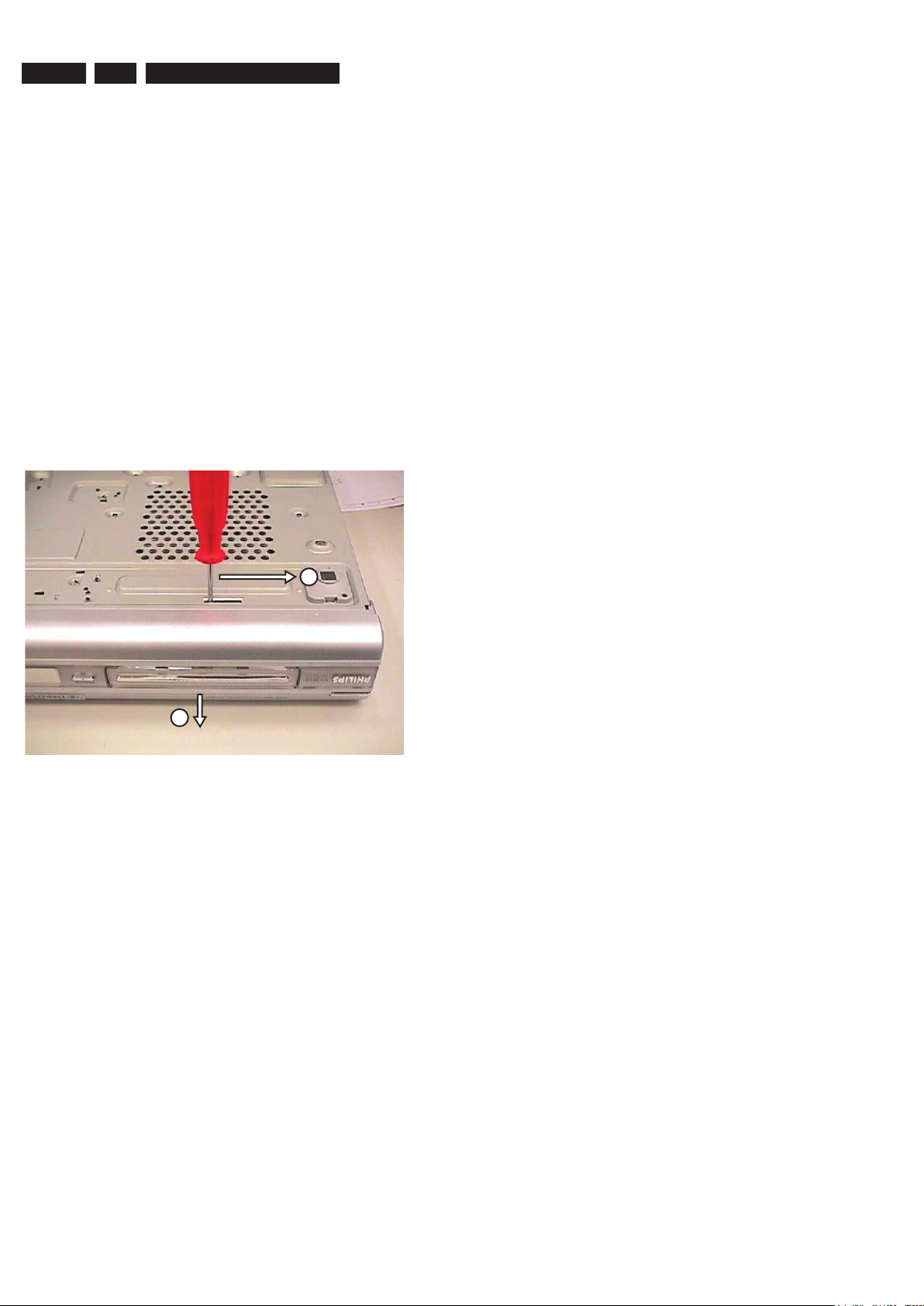
2.2 Open the DVD Tray manually
Note: This procedure needs to be performed on
condition that:
- a customer’s Disc is jammed in the DVD Tray
- the DVD Tray cannot be open via the normal
open/close button on the set.
1) Place the set on the table with the bottom faced upwards
2) Insert a screw driver into the slot and open the DVD Tray
as shown below.
by sliding the screw driver in the direction shown.
1
2
Figure 2-1

Firmware Upgrading & Diagnostic Software
Jeanne van Woerkom electra
3139 785 31800
3.
EN 7
3. Firmware Upgrading & Diagnostic Software
3.1 Firmware Upgrading
A. Preparation to upgrade firmware:
1. Unzip the zip-archive file
2. Start the CD Burning software and create a new CD project (data disc) with the following settings:
File system : Joliet
Format : MODE 2: CDROM XA
Recording mode : SINGLE SESSION (TRACK-AT-ONCE), FINALIZED CD
Note: Long file name is necessary for the preparation of the upgrade disc
3. Place the content of the zip-archive into the root directory of the new CD project.
4. Burn the data onto a blank CDR or CD-RW
B. Procedure to apply the firmware upgrade:
1. Hold the <Record> + <Open/Close> buttons down and Power up the set.
2. The tray opens and set will display:
FORCE DL −>…. INSERT DISC
3. Insert the prepared Upgrade CDROM and close the tray.
4. The set will display:
INIT DSC −> ………. SYS VER −> READ FILES …. DOWNLOAD BE
The whole process takes less than 15 minutes
Note: Do not press any buttons or interrupt the mains supply during the upgrading process, otherwise the set may becomes
defective.
5. When the upgrade is completed the tray will open automatically and the set will display:
REMOVE DISC
6. Close the tray and the set will display:
DONE
7
The set will go into Standby mode.
C. How to read out the firmware version to confirm set has been upgraded:
1. Power up the set.
2. Press <System> button on the Remote control and select {Setup} option
3. Press <Right> button to select {System}
4. The set will prompt you about clearing the Time Shift Buffer
5. Select {Yes} and press <OK> button
6. Press <Down> button several times to select {Version info}
7. Press <OK> button
8. The TV connected to the set will display:
(C) PHILIPS 2006 VERSION INFORMATION:
DIF05_8/7028 AN SV11226
BE 43.3.7.9 ASP 1,18,1,10FP
DTTM HW:01020102 DTTM
SW:00040206
SIT7250H-FF5F-S28_F604
20060203-1650 pro sxcplusint
EPG:3.06 DPMS:P_DPM
9. Press <System> button to exit
EN 8
3139 785 31800
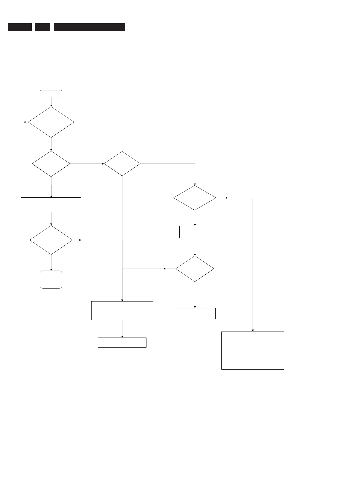
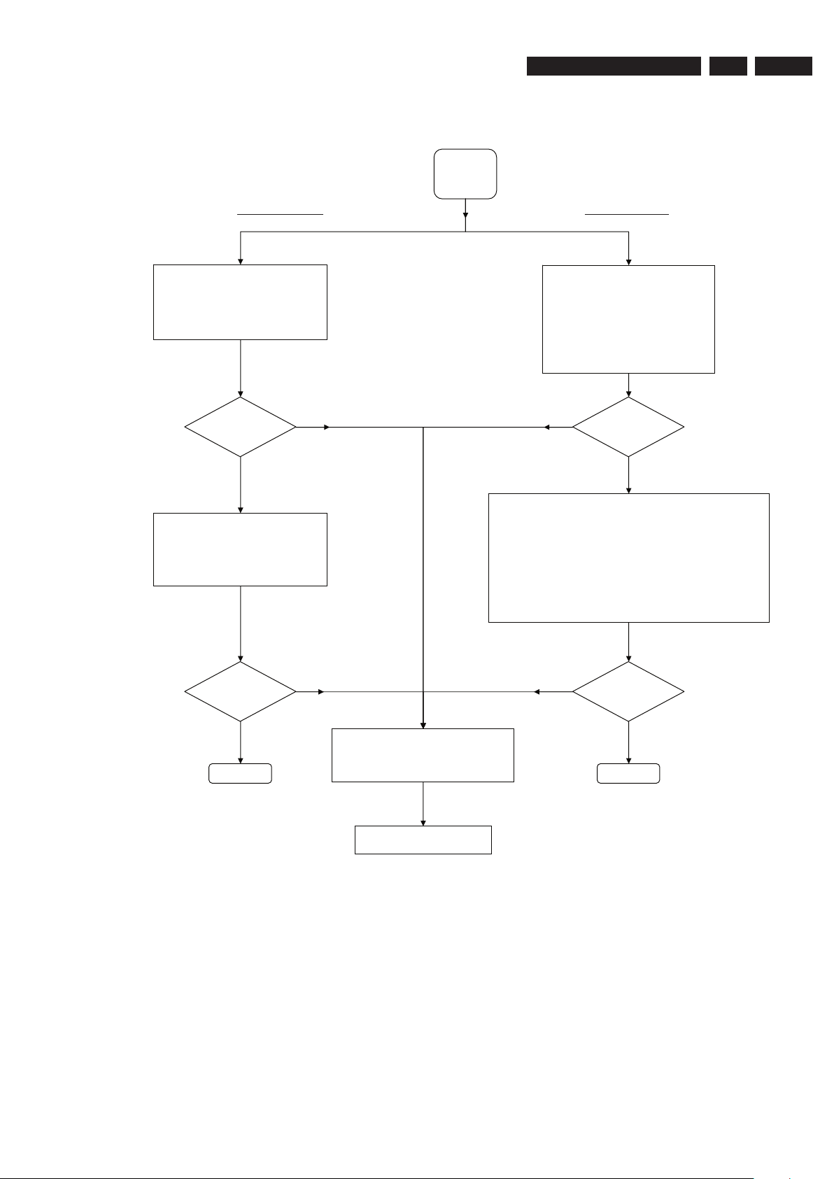
Start
A
(Verification
Test)
Is it a
Hardware
problem ?
Upgrade to latest
Firmware
Is it a known
complaint ?
Is Firmware
solution
available ?
Yes
No
Yes
No
Yes
No
Is the
complaint
solved ?
Return set to Customer with
Report on action done
Yes
No
Is the
complaint
documented ?
Yes
No
Service W/S to contact the Trade /
Customer to work out an action plan.
Examples:
- explain them that the Firmware
solution is not ready
- Upgrade disc will be send to them the
moment a solution is ready
- etc.
Does the set
pass the
Dealer Test ?
Pass
Fail
Perform built-in Dealer Test
(Press & hold Play button on Front Panel
down + Power-up the set)
Send refurbished set from pool
stock to Trade / customer
- Attached Defect Description Report
and Proof of Purchase.
- Pack defective set
- Store defective set for pick-up
Jeanne van Woerkom electra
4.
4. Service Flow Chart
4.1 Start Process
Service Flow Chart
4.2
* If complaint is related to
System Menu setting
Connect up the Recorder
to TV antenna, TV set
and an External source
Check the Firmware
version on the set
Can the set
Start-up ?
Yes
No
A
(Verification
Test)
B
Recording
Check
C
Playback
Check
D *
System Menu
Send refurbished set from pool
stock to Trade / customer
Return set to Customer with
Report on action done
- Attached Defect Description Report and
Proof of Purchase.
- Pack defective set
- Store defective set for pick-up
No
Yes
Is Firmware the
last released
version ?
Upgrade to latest
Firmware
Are the
checks result
ok ?
Yes
No
Jeanne van Woerkom electra
Verification Process
Service Flow Chart
3139 785 31800
4.
EN 9
EN 10
3139 785 31800
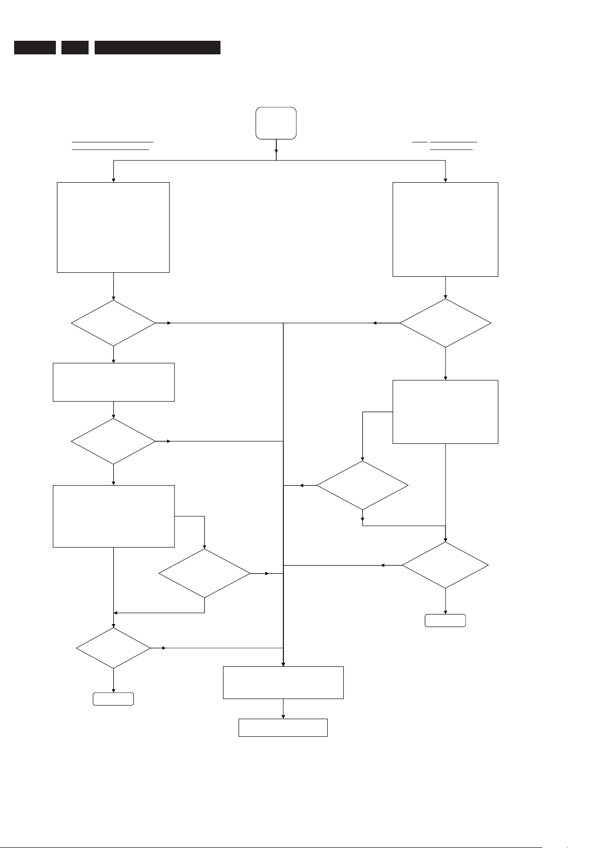
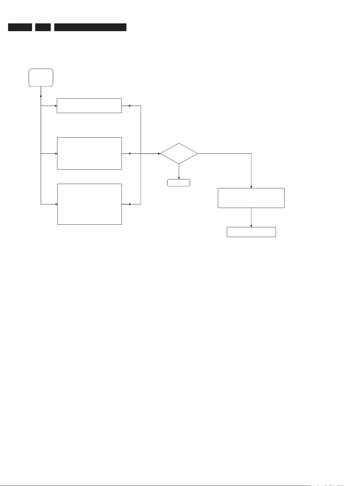
Manual Recording during TSVB HDD: Manual Recording
Copy to DVD Recordable disc Timer Recording
Does Timer
recording
functions ?
Yes
No
Does manual
recording
No
functions ?
Yes
B
Recording
Check
Make a Timer recording with:
- VPS/PDC on and off
- Guide Plus+ System
- Show View System
- manual selection
Playback the recorded title from HDD
browser
A
re Timer edit &
delete feature
working ?
Yes
No
Make a manual recording to the HDD
using different recording source:
- Cam (DV-in)
- Cam 1 (Front CVBS/S-Video)
- Tuner
- Rear Ext 1/2 (external Cable
Box/Satellite Receiver/VCR/DVD)
From the HDD browser select the
recorded title and check the following:
- edit title feature
- play the title
Does the
TSB feature
works ?
1) Switch the Recorder to Tuner source
- The active Tuner channel will be
recorded into the TSB (time shift
buffer), a temporary HDD storage
area.
2) By pressing the "INFO" button the
Time Shift video bar (TSVB) appears
on the screen, check the following
features:
- search forward / backward
- instant replay, pause, etc. on the
live TV function
1) Make a short recording (stop > 1 minute)
by during Time Shift video bar display.
2) Playback the recorded title from the
HDD browser
Does the
recording
functions ?
Continue
Continue
Yes
No
Yes
No
Send refurbished set from pool
stock to Trade / customer
- Attached Defect Description Report and
Proof of Purchase.
- Pack defective set
- Store defective set for pick-up
1) Insert a DVD+RW disc
2) In the HDD browser select the recorded
title for copy to recordable DVD
3) From the Disc Menu select the copied
title and check the following:
- edit features
- play the title
4) Repeat with DVD-RW
Does copy
function ?
Yes
No
Is the Disc
Library feature
working ?
Yes
No
Jeanne van Woerkom electra
Recording Process
4.3
4.
Service Flow Chart
4.4
HDD playback Check Disc playback Check
Yes
No
C
Playback
Check
Playing other type of disc:
1) Use discs of DVD PLAYER TEST PACK for:
- (Super) Video CD
- MP3 disc
- Picture disc (slide show)
- special DVD playback check by layer change test u
DVD disc of this package
2) For AUDIO CD use of CD-RW printed Audio Disc to check:
- Track 3 finger print
- Track 8: 600u black dot (max. after 1 min.)
sing
From the DVD Menu or DVD Browser go
through the Content, Title & Toolbar
options.
Play a DVD video disc title and check the
following:
- Pause, Search Fwd/Rev & Next /
Previous chapter
- Edit features
- T/C search
Yes
No
Does the set
work ?
From the HDD browser check the
following features:
- Sorting
- Titles: Delete, Copy & Protect
- Play / Edit features
Does the set
work ?
ContinueContinue
Yes
No
Send refurbished set from pool
stock to Trade / customer
- Attached Defect Description Report and
Proof of Purchase.
- Pack defective set
- Store defective set for pick-up
Does the set
work ?
Play a title from the HDD browser and
check the following features:
- Pause, Search Fwd/Rev & Next /
Previous chapter
- Editing features
-
Yes
No
Does the set
work ?
Jeanne van Woerkom electra
Playback Process
Service Flow Chart
3139 785 31800
4.
EN 11
EN 12
3139 785 31800
D
System Menu
Check
Does the
set work ?
Continue
Yes
No
Toolbar - check the following features:
- Option
Setup - check the following features:
- System
- Time-date
- Analogue Ch
- Digital Ch
- Video output
- Audio output
- Audio input
- Language
Preferences - check the following features:
- Recording
- DV Specials
- Sound
- Disc
- Access
- Features
Send refurbished set from pool
stock to Trade / customer
- Attached Defect Description Report and
Proof of Purchase.
- Pack defective set
- Store defective set for pick-up
Jeanne van Woerkom electra
4.5
4.
System Menu
Service Flow Chart
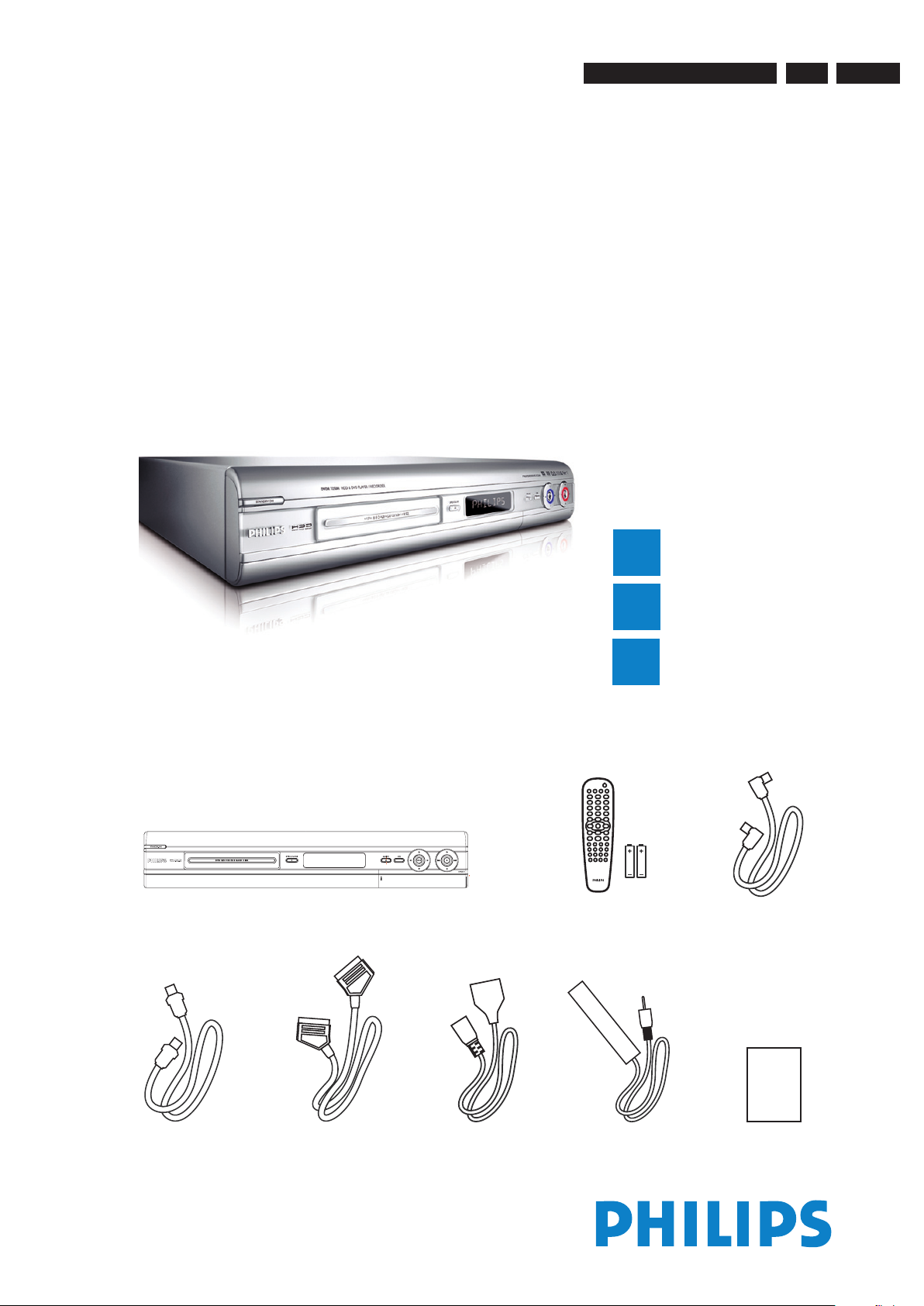
Directions For Use
HDD & DVD Player / Recorder DVDR7250H
Quick Start Guide
Connect
Set up
Enjoy
1
2
3
What’s in the box?
HDD & DVD Player / Recorder
RF coaxial cable
Remote Control
and 2 batteries
User ManualScart cable
Tuner interlink cable
Power cable G-LINK cable &
transmitter
Jeanne van Woerkom electra
3139 785 31800
5. Directions For Use
The following except of the Quick Use Guide serves as an introduction to the set.
The Complete Direction for the Use can be downloaded in different languages from the internet site of Philips Customer care Center:
www.p4c.philips.com
5.
EN 13
EN 14
3139 785 31800
1
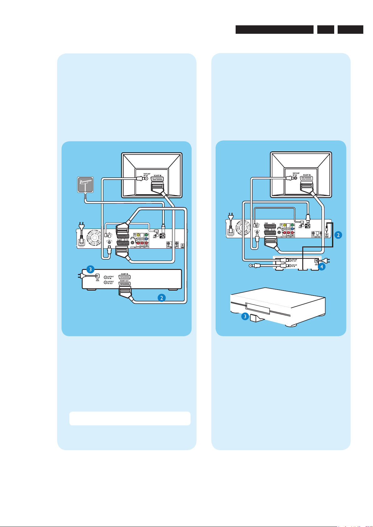
Connect
Start with the ‘Basic connection’.
If you have a VCR, follow the instructions for ‘Connection with VCR or similar device’.
If you have a set-top box, follow the instructions for ‘Connection with set-top box’.
Basic Connection
A
Before Connecting
Unplug the antenna cable that is currently connected to
your TV.
If you have only a single off-air antenna, follow ‘B1’
connection.
If you have both the off-air antenna and digital terrestrial
antenna, follow ‘B2’ connection.
Connecting
A Disconnect the antenna cable from your TV and
connect it to the ANTENNA
socket on this
recorder.
B Use the supplied RF coaxial cable to connect the TV
socket on this recorder to the Antenna In socket
on the TV.
C Use the supplied Tuner interlink cable to connect
the two ‘A’-sockets on this recorder.
D Use the supplied scart cable to connect the
EXT1 TO TV-I/O scart socket on this recorder to
the SCART IN socket on your TV.
E Plug in the power cable from the recorder to an AC
power outlet
A Disconnect the antenna cable from your TV and
connect it to the
socket on this recorder.
B Connect the indoor DVB-T antenna cable to the
ANTENNA
socket on this recorder.
C Use the supplied RF coaxial cable to connect the
TV
socket on this recorder to the Antenna In
socket on the TV.
D Use the supplied scart cable to connect the
EXT1 TO TV-I/O scart socket on this recorder to
the SCART IN socket on your TV.
E Plug in the power cable from the recorder to an AC
power outlet
A Follow step 1 to 5 of ‘Basic connection’ to connect
this recorder before you proceed to step 2 below.
Above illustration shown the connection without
the digital terrestrial antenna.
B Use another scart cable (not supplied) to connect
the EXT2 AUX-I/O scart socket on this recorder to
the SCART OUT socket on your VCR.
C Connect the power cable from the VCR to an AC
power outlet.
B1
Connecting (with digital terrestrial
antenna)
B2
Connection with VCR or
similar device
A
Your new Philips Recorder replaces the VCR for your
recording needs. First, unplug all the connections from
your VCR.
B
From an off-air
antenna or
cable box
Television ( rear)
Television (rear)
From an offair antenna or
cable box
Philips Recorder (rear)
Philips Recorder (rear)
From digital
terrestrial
antenna
Note See the accompanying user manual for other possible connections (e.g. S-Video, Component Video)
Philips Recorder
(rear)
Setup External Receiver 1
Has the External Receiver 1 changed to
Programme Number 101?
From an off-air
antenna or cable box
Jeanne van Woerkom electra
5.
Directions For Use
Directions For Use
2
A
A Presss STANDBY-ON on the recorder.
B Turn on the TV.
C In case you don’t see the recorder’s setting menu,
B
Use the recorder’s remote control and follow the on-
screen instructions to complete the installation.
A Select the desired menu language, your country and
B Activate automatic channel search for analogue and
C Check the date and time and press
D To continue with the GUIDE Plus+ installation,
C
A Follow the on-screen instructions to select your
A Follow step 1 to 5 of ‘Basic connection’ to connect
this recorder before you proceed to step 2 below.
Above illustration shown the connection without
the digital terrestrial antenna.
B Use another scart cable (not supplied) to connect
the EXT2 AUX-I/O scart socket on this recorder to
the SCART OUT socket on your VCR.
C Connect the power cable from the VCR to an AC
power outlet.
Note In this setup, the VCR cannot record TV
programmes.
Connection with set-top box
Your new Philips Recorder provides a G-LINK
transmitter which allows you to control the tuner of the
set-top box (satellite receiver, cable TV box) through
the GUIDE Plus+ system. You can record the TV
programmes that are received through the set-top box.
Connecting
To source
A Follow step 1 to 5 of ‘Basic connection’ to connect
this recorder before you proceed to step 2 below.
Above illustration shown the connection without
the digital terrestrial antenna.
B Connect the supplied G-LINK cable to the G-LINK
socket on this recorder.
C Place the G-LINK transmitter in front of your set-
top box in such a way that it can acquire the signal
broadcasted by the transmitter.
D Connect the power cable from the set-top box to
an AC power cable.
Connection with VCR or
similar device
A
Before Connecting
Your new Philips Recorder replaces the VCR for your
recording needs. First, unplug all the connections from
your VCR.
B
Connecting
Television ( rear)
Television ( rear)
VCR or similar
device (rear)
Philips Recorder
(rear)
G-LINK transmitter
Set-top box
Positioning of G-LINK
transmitter
Set-Top Box (rear)
Setup External Receiver 1
Has the External Receiver 1 changed to
Programme Number 101?
From an off-air
antenna or cable box
Jeanne van Woerkom electra
3139 785 31800
5.
EN 15

EN 16
3139 785 31800
2
Set up
A
Finding the viewing channel
A Presss STANDBY-ON on the recorder.
The recorder will display ‘IS THE TV ON?’.
B Turn on the TV.
You should see the { EASY SETUP } menu.
Note If your VCR is connected to this recorder,
ensure it is turned off or in standby before proceeding.
C In case you don’t see the recorder’s setting menu,
press the Channel Down button on the TV’s remote
control repeatedly (or AV, SELECT, ° button) until
you see the menu. This is the correct viewing
channel for the recorder.
B
Start basic setup
Use the recorder’s remote control and follow the onscreen instructions to complete the installation.
A Select the desired menu language, your country and
the TV shape.
Note Select { Done } in the menu and press
to go
to the next screen.
B Activate automatic channel search for analogue and
digital tuner/radio.
C Check the date and time and press
.
D To continue with the GUIDE Plus+ installation,
select { Continue } and press
.
Otherwise, select { Do not install now } and press
. Wait until the recorder has finished initialising
the system, then press
again.
C
Install the GUIDE Plus+ system
A Follow the on-screen instructions to select your
language, country and enter the postal code of your
area.
Note If no or wrong postal code is entered, it will
cause no GUIDE Plus+ (EPG) service information.
D
Install the set-top box
If you do not have a set-top box, skip ‘D’ and go to ‘E’.
A Press � down to select ‘External Receiver 1’ and
press
.
B Press again to continue.
C Select the type of reception, service provider and
brand name of the connected set-top box.
Note Press
to go to the next screen. Select
{ None } if none of the entries are applicable.
D Select the recorder socket through which your set-
top box is connected (e.g. ‘EXT2’ for EXT2 AUX-I/O
socket) and press
.
E Turn on your set-top box and select channel
number 02 on the set-top box.
F Read the instructions on the TV and press .
Setup External Receiver 1
Has the External Receiver 1 changed to
Programme Number 101?
G If the set-top box has switched to the same
programme number as displayed on the TV, select
{ Yes } in the menu and press
.
Note If not, select { No } and press
to try a
different code.
H Your set-top box is now installed. Press the green
button to exit.
Note To switch the GUIDE Plus+ system’s host
channel manually, go to { Host Channel Setup }.
E
Load the TV listing data
A Press GUIDE
to exit GUIDE Plus+ system.
Leave the recorder in ‘standby’ mode and turn ‘on’
the set-top box overnight to collect the TV listing
data, this may take up to 24 hours.
Note If you tune to your Host Channel before going
to ‘standby’ mode, this recorder will start downloading
the TV listings data immediately.
B Check the { Editor } screen the next day to ensure
the source and programme numbers are matching
for all channels.
Jeanne van Woerkom electra
5.
Directions For Use
3
Enjoy
About the Time Shift Buffer
(TSB)
Once you turn on the recorder, the selected TV
programme will be stored in a temporary hard disk
storage called the ‘TSB’ (Time Shift Buffer). The ‘TSB’
can store up to 6 hours of programmes temporarily.
Press
INFO
once to display the Time Shift video bar.
23:13
21:00
The contents in the time shift video bar will be cleared
when you press STANDBY ON (2).
Note A con rmation message on clearing the Time
Shift Video bar will be appeared if you press the CAM
button on the remote control or access the { Setup }
or { Record mode } option in the setup menu.
Watch TV – Pause live TV
Your Philips Recorder allows you to control the TV
programme. You can PAUSE it as if you were in control
of the live broadcast.
A Turn on your recorder and press TUNER to switch
between analogue and digital tuner, then press
CHANNEL +/- to select a TV programme.
B Press PAUSE
to suspend it.
C Press PLAY
to continue.
D Press TUNER to return to the live broadcast.
Help text information bar
The help text bar located at the bottom of the screen is
providing the information on:
remote control keys that can be used at the current
state.
brief information of the selected item.
Need help?
GUIDE Plus+ system
Go to www.europe.guideplus.com
User Manual
See the user manual that came with your Philips Recorder
Online
Go to www.philips.com/support
Record to hard disk
A
Contents in the temporary HDD
storage
A Press INFO to view what is temporarily stored
in the hard disk storage.
B Press up or down to choose the title you
want to record.
C Press to search for the scene where you want
to start recording, then press the red
button.
Note Pressing the red
button again will cancel
the recording.
D Press STOP to end the recording.
Note The title will be marked in red and the
recording will only take effect when you turn off the
recorder.
B
Current TV programme
A Press REC
to start recording. It can record up
to 6 hours.
Note To set the recording time, press
repeatedly
to extend the recording time in 30-minute increments,
up to 6 hours. If GUIDE Plus+ system is available,
‘Record 1 program’ is displayed and the current
programme will be recorded.
B To stop the recording before the scheduled time,
press STOP
.
Start playback
A
From the hard disk
A Press HDD-BROWSER , then press right
until you see the { TITLES } and { INFO } menus.
B Press up or down to select a title.
C Press PLAY
B
From a disc
A Hold down STOP
Load a disc and close the disc tray.
B Press HDD-BROWSER to go to the content
menu. Select { Disc Tray } and press right until
you see the { TITLES }, { TRACKS } or { PHOTO
ROLLS } menu, depending on the disc type.
C Press up or down to select a title.
D Press PLAY to start playback.
Current time of
playback
End time of
the buffer
Selected clips for
recording
Programmes
stored in the ‘TSB’
Start time of the
programme
Programme
information
GUIDE
Jeanne van Woerkom electra
Directions For Use
3139 785 31800
5.
EN 17
EN 18
Need help?
GUIDE Plus+ system
Go to www.europe.guideplus.com
User Manual
See the user manual that came with your Philips Recorder
Online
Go to www.philips.com/support
Start playback
A
From the hard disk
A Press HDD-BROWSER , then press right
until you see the { TITLES } and { INFO } menus.
B Press up or down to select a title.
C Press PLAY
to start playback.
B
From a disc
A Hold down STOP
until the disc tray opens.
Load a disc and close the disc tray.
B Press HDD-BROWSER to go to the content
menu. Select { Disc Tray } and press right until
you see the { TITLES }, { TRACKS } or { PHOTO
ROLLS } menu, depending on the disc type.
C Press up or down to select a title.
D Press PLAY to start playback.
Using the GUIDE Plus+ system
Make sure that the analogue tuner installation and TV
listing data download is completed.
Record TV programmes
A Press GUIDE
.
B Press down to select a TV channel.
Note Press the yellow
button to see an overview
of all the available channels and choose from there.
C Press left or right to select a TV programme.
Note Press
to go directly to a day before or
the next day TV listings.
D Press the red
button to set the highlighted
programme for recording.
Note You can store up to 25 programmes for
recording.
2005 © Koninklijke Philips N.V.
All rights reserved.
12 NC 3139 246 19731
www.philips.cocm
HDD & DVD Player / Recorder DVDR7250H
Quick Start Guide
What’s in the box?
RF coaxial cable
GUIDE
Jeanne van Woerkom electra
5.
3139 785 31800
Directions For Use

123456
Jeanne van Woerkom electra
0803 E4
1700 E1
2700 A2
2701 B3
2702 A2
2703 D3
A
1
B
A
C
B B
D
1700
TMQZ2
owner.
is prohibited without the written consent of the copyright
All rights reserved. Reproduction in whole or in parts
E
C
F
D
G
2705 E3
2707 C3
7701
BC857BW
I700
3704
I701
1920
VIDOUT
RFAGC
TUNER
SIFOUT
100R
18
GND2
GND1
AOUT
21
VFV
AFT
VTU
NC5
SDA
SCL
NC4
NC3
NC2
NC1
2708 C4
2709 B3
2710 C1
to IOV,FOME
F705
17
16
15
14
13
MB
12
11
BB
2711 C1
2712 D4
3700 A2 5706 D4
3701 A2
3704 B1
3706 A1
23
5V
SIF1
to MSP
2702
3706
2K2
8
7
6
5
4
3
2
1
100n
2700
22n
3700
47K
3701
47K
not used
I703
10
9
F701
5700
5700 A22704 E3
5702 D3
5703 C4
22u
2701
2711
25V
22u
6.3V47u
F704
2710
F703
F702
5704 C4
5705 D3
2709
I704
I706
10n
5705
10n
2703
Bead
100n
7701 A1
F700 D1
F701 E3
5VSTBY
5VSTBY
47p
2707
delete for DTTM
33VSTBY
F702 D3
F703 D3
F704 C3
from PS
5V
5V
5704
Bead
not used
10u
5702
2708
F705 B1
I700 A1
I701 B1
4
33VSTBY
33VSTBY
5703
Bead
47p
not used
2712
I705
I707
5706
10u
25V10u
for DTTM only
I703 B2
I704 C3
I705 C4
from/to CU
SCL_5V
from CU
SDA_5V
5VSTBY
I706 C3
I707 C4
A
B
A
C
D
E
C
F
D
G
-403A
E
H
I
CHN SETNAME dvdrw_2004
CLASS_NO
3PB120
J
2004-03-2623
NAME
1
Frontend Video FV
Friedreich
CHECK DATE
PB AB 04 E1
SUPERS.
123456
2003-01-13
50V4u7
10n
50V
2704
2705
0803
BARCODE
E
H
I
21
10
3
3103 603 3035
C
ROYAL PHILIPS ELECTRONICS N.V. 2005
130
4
2006-01-27
7
6
2005-07-07
0
2004-10-22
0
2004-05-07
0
2004-03-25
1
J
A4
1 2 3 4 5 6 7 8 9 10 11 12 13 14 15 16 17 18 19
Jeanne van Woerkom electra
20
A
12VSTBY
5VSTBY
B
A
12VSTBY
5VSTBY
C
B
D
E
C
WU
to CU
BC857BW
I404
2402
220n
F
D
G
E
H
I
F
J
G
WSFI
to CU
K
AINFL
to IOA
AINFR
All rights reserved. Reproduction in whole or in parts
is prohibited without the written consent of the copyright
owner.
L
H
M
to IOA
1942
AINFR
GND
AINFL
CVBSFIN
GND
NC
CFIN
GND
from/to FRONT A/V
YFIN
1
2
3
4
5
6
7
8
9
B9B-PH-K
I
N
1
from PS
5V
5V
5VSTBY
7403
3K9
3408
I405
F4201
F4203
F4204
F4207
F4209
5NSTBY
5NSTBY
BC857BW
I406
3405
5VSTBY
7401
22K
from PROG
5NESD
5NESD
BC847BW
82K
3489
10u 16V
5VSTBY
7402
2450
I407
3406
not used
2428
2421
10u16V
100n
470K
2412
I409
3407
5NSTBY
10n
I408
3K3
3429
47K
CVBSIN
3446
3447
to FOME
47K
47K
2459
100n
2401
2410
3490
SCART 1
3404
100p
not used
100n
150R
2404
3435
I422
I423
F4021
1%
75R
6401
5NESD
100n
150R
I419
I420
CVBSIN1
GND
21A
F4020
BZX384-C12
3445
I418
YCVBSOUT1
19A
20A
F4019
150R
3414
7412
NJM2234M
43
GND
GND
18A
6414
6420
BZX384-C6V8
1%
75R
1
VIN1
3
VIN2
5
VIN3
2
SW1
4
SW2
I421
NJM2235M
1
VIN1
3
VIN2
5
VIN3
2
SW1
4
SW2
RCOUT
FBOUT
17A
F4016
BZX384-C6V8
3412
16A
F4015
3409
75R
Φ
15A
6402
1%
75R
5V
V+
3-INPUT
VIDEO SW
VOUT
GND
8
5V
6
7413
V+
Φ
3-INPUT
VIDEO SW
VOUT
GND
8
GND
GND
13A
14A
6403
BZX384-C6V8
2406
1u0
6
7
2407
1u0
5
NC
12A
F4011
BZX384-C6V8
3413
7
GOUT
11A
F4010
1%
75R
3422
I402
5VSTBY
5V
3437
P50
10A
3430
2403
10K
GND
9A
6423
BAT54 COL
820R
4K7
100n
5V
3438
8SC1
BOUT/CIN
8A
F4008
F4007
BZX384-C12
6421
6410
BAS316
7404
BC817-25W
10K
7A
F4006
3403
AIN1L
6A
6404
5NESD
1%
75R
62
GND
GND
4A
5A
F4003
BZX384-C12
2424
12VSTBY
7405
BC847BW
7407
BC847BW
2419
1u0
7416
BC847BW
AOUT1L
3A
F4002
470p
5NESD
I467
BC847BW
33K
3424
3410
75R
2413
1u0
AOUT1R
AIN1R
2A
F4001
6405
BZX384-C12
12VSTBY
7409
1%
5VSTBY
3451
2417
16V 10u
1A
10K
1940-1
2425
3421
3423
3450
ROW_A
27K
390R
BC847BW
3428
100K
7
AIN1R
MRC-021V-10 PC
6406
3443
3426
2447
10n
not used
1u0
from FV
VFV
3472
BZX384-C12
7414
BC857BW
47K
33K
3442
470p
5NESD
7415
2446
100K
to IOA,MSP
2426
100K
3441
470K
150K
5VSTBY
3439
F444
3433
100R
from/to CU
SDA_5V
3475
6407
470p
5NESD
3448
10K
I461
I462
I463
I464
I465
I466
I415
I416
I417
I468
I401
I403
I469
I470
3432
SCL_5V
from IOA
AOUT1R
100R
2429
BZX384-C12
3444
18K
100K
2411
34
33
40
41
1
43
28
42
44
2
14
16
18
38
37
100R
from/to CU
8
from IOA
AOUT1L
3476
100R
470p
6408
BZX384-C12
5NESD
5VSTBY
2414
100n
100n
20
36
VDD
VCCB-REC
R|PR|COUT-TV
G|YOUT-TV
B|PBOUT-TV
FBOUT-TV
Y|CVBSOUT-TV
CIN-TV
Y|CVBSIN-TV
Y|CVBSIN-TUN
CIN-TUN
C-GATE
1
VS
CS
2
3
DIGOUT
4
5
6
SDA
SCL
GNDB-REC
22
AIN1L
3471
8
VCC
to IOA,MSP
100K
I456
2435
7408
STV6618D
P50
from/to CU
6409
BZX384-C6V8
5VSTBY
5406
2434
100n
Φ
MRC-021V-10 PC
10u
6.3V47u
VIDEO SWITCH
MATRIX
Y|CVBSOUT-REC
Y|CVBSOUT-AUX
GND1
GND2
3
12
9
MT2
1940-3
MT1MT2
4401
not used
24
30
32
VCCB3
VCCB2
VCCB1
R|PR|CIN-ENC
G|YIN-ENC
B|PBIN-ENC
CVBSIN-ENC
CIN-ENC
YIN-ENC
DECV
COUT-AUX
R|PR|CIN-AUX
G|YIN-AUX
B|PBIN-AUX
FBIN-AUX
Y|CVBSIN-AUX
GNDB
GNDD
39
26
I414
2409
1029
1127
21
23
25
17
15
13
35
19
3427
5VSTBY
100n
931
4
6
7
5
SCART 2
1%
75R
6424
5NESD
10u
5402
2405
47u 6.3V
I483
2441
I482
1u0
I481
2437
1u0
I479
2438
I478
1u0
2433
47n
I476
3449
75R
2418
1u0
2427
1u0
3452
150R
GND
21B
F4121
F4120
BZX384-C12
2440
1u0
2436
1u0
2439
1u0
2423
1u0
3494
150R
10
YCVBSIN2
CVBSOUT2
20B
19B
F4119
75R
3411
2416
1u0
GND
18B
6419
BZX384-C6V8
GND
17B
FBIN
16B
F4116
GND
RCIN
15B
F4115
3401
75R
6415
BZX384-C12
6422
BZX384-C6V8
3417
75R
GND
14B
1%
5VSTBY
2408
11 12 13
13B
3491
3436
NC
12B
F4211
5NESD
5NESD
3492
150R
4K7
100n
GIN
P50
10B
11B
F4110
3402
1%
75R
6416
BZX384-C12
150R
3425
7406
BC817-25W
GND
9B
75R
F4108
5NESD
1%
8SC2
8B
F4107
3493
BIN/COUT
AIN2L
6B
7B
F4106
2431
150R
5NESD
GND
470p
6425
5NESD
6417
5B
GND
AOUT2L
3B
4B
F4103
3470
BZX384-C12
BZX384-C12
5VSTBY
3431
2422
AIN2R
F4102
100K
4K7
3434
4K7
10n
2B
F4101
2443
6418
100n
2415
AOUT2R
1940-2
1B
470p
6412
5NESD
BZX384-C12
I411
ROW_B
5V
3416
3418
to IOA
to IOA
AIN2L
AIN2R
MRC-021V-10 PC
3469
100K
BZX384-C12
F4720
5V
27K
22K
3415
I410
I412
3420
2442
F4701
F4703
F4705
F4707
F4709
F4712
F4714
F4716
F4718
F4721
F4722
1K0
3440
100R
7411
BC847BW
100R
I451
3478
6411
470p
5NESD
3419
100R
AOUT2L
14
from MSP
2444
1947
100n
I413
3477
470p
6413
5NESD
A_VR
GND
A_UB
GND
A_YG
GND
A_C
GND
A_YCVBS
GND
GND
D_CVBS
GND
D_Y
GND
D_C
GND
D_VR
GND
D_YG
GND
D_UB
5V
7410
BC857BW
2420
100R
BZX384-C12
1
2
3
4
5
6
7
8
9
10
11
12
13
14
15
16
17
18
19
20
21
22
22FMN-BTRK-A
2430
from MSP
AOUT2R
100R
BZX384-C12
2432
100n
1940-1 A7
1940-2 A13
1940-3 A9
1942 H1
1947 C14
2401 B3
2402 C1
2403 E5
2404 F3
2405 E9
2406 F5
2407 H5
2408 H11
2409 E9
A
2410 E3
2411 D8
2412 G2
2413 F6
2414 D8
2415 H12
2416 H10
2417 H6
2418 G9
2419 F6
2420 I14
2421 I2
2422 I12
B
2423 G10
2424 B6
2425 B7
8SC2
to CU
FB
to CU
2426 B7
2427 G9
2428 H2
2429 B8
2430 G14
2431 B12
2432 G14
2433 F9
2434 D8
C
2435 D8
2436 E10
2437 F9
2438 F9
2439 F10
2440 E10
2441 E9
2442 B13
2443 B12
2444 B14
2446 G7
2447 E7
2450 C2
D
2459 G3
3401 B11
3402 B11
3403 D6
3404 B3
3405 C1
3406 C2
3407 C2
from/to DIGTAL BOARD
3408 C1
3409 B4
3410 E6
3411 B10
3412 C4
E
D_VR
to PROG
D_YG
to PROG
D_UB
to PROG
D_CVBS
to PROG
3413 B5
3414 C4
3415 G13
3416 G13
3417 B11
3418 H13
3419 H14
3420 I13
3421 C6
3422 C5
3423 D6
D_Y
to PROG
F
3424 D6
3425 H11
3426 D7
3427 B9
3428 D7
3429 G2
3430 D5
3431 I12
3432 H7
3433 H7
3434 I13
3435 G3
3436 H11
3437 H5
G
3438 H5
3439 E7
3440 H13
22u 16V
3441 C7
3442 D7
3443 C7
3444 D8
3445 C4
3446 B3
3447 B3
3448 D7
3449 G9
3450 H7
H
3451 G6
3452 H9
3469 B13
3470 B12
3471 B8
3472 B7
3475 A7
3476 A8
3477 A14
3478 A13
3489 G2
CRout
to PROG
I
3490 F3
3491 C11
3492 C11
3493 C12
3494 G10
4401 A9
5402 D9
5406 D8
6401 B3
6402 B4
6403 B5
6404 B6
6405 B6
6406 B7
6407 B7
6408 B8
6409 B8
6410 C5
6411 B13
6412 B13
6413 B14
6414 B4
6415 B11
6416 B11
6417 C12
6418 C12
6419 B10
6420 B4
6421 C5
6422 B11
6423 B5
6424 B9
6425 B12
7401 C2
7402 B2
7403 C1
7404 D5
7405 C6
7406 H11
7407 D6
7408 E8
7409 D7
7410 H14
7411 H13
7412 G4
7413 I4
7414 C7
7415 D7
7416 H6
F4001 A6
F4002 A6
F4003 A6
F4006 A6
F4007 A5
F4008 A5
F4010 A5
F4011 A5
F4015 A4
F4016 A4
F4019 A4
F4020 A4
F4021 A3
F4101 A12
F4102 A12
F4103 A12
F4106 A12
F4107 A12
F4108 A11
F4110 A11
F4115 A10
F4116 A10
F4119 A10
F4120 A10
F4121 A10
F4201 H1
F4203 H1
F4204 H1
F4207 H1
F4209 I1
F4211 A11
F444 G7
F4701 C13
F4703 C13
F4705 D13
F4707 D13
F4709 D13
F4712 D13
F4714 D13
F4716 D13
F4718 E13
F4720 E13
F4721 E13
F4722 E13
I401 G7
I402 C5
I403 H7
I404 C1
I405 G1
I406 C2
I407 C2
I408 B2
I409 B2
I410 H13
I411 H13
I412 H13
I413 H14
I414 D9
I415 G7
I416 G7
I417 G7
I418 G4
I419 G4
I420 G4
I421 H4
I422 I3
I423 I3
I451 I13
I456 D8
I461 E7
I462 E7
I463 E7
I464 F7
I465 F7
I466 F7
I467 D6
I468 G7
I469 H7
I470 H7
I476 F9
I478 F9
I479 F9
I481 E9
I482 E9
I483 E9
A
B
C
D
E
F
G
H
I
J
K
L
M
N
O
P
1
2
3
4
65
7
8
9
654321 201918171615
10 11 12
CHN SETNAME dvdrw_2004
CLASS_NO
3PB120
1
2
2004-03-26
NAME
Neubauer
3
CHECK
1413121110987
13 14
PB AB 04 E1
Video In/Out IOV
SUPERS.
DATE
2003-01-13
10
O
7
2006-01-27
6
2005-07-07
0
2004-10-22
3103 603 3035
0
2004-05-27
0
2004-05-07
2
130
C
ROYAL PHILIPS ELECTRONICS N.V. 2005
A2
P
1234 56
Jeanne van Woerkom electra
A
A
B
RSA2
RSA1
from MSP
C
D
All rights reserved. Reproduction in whole or in parts
is prohibited without the written consent of the copyright
owner.
E
B
C
D
AINFR
from IOV
AINFL
from IOV
AIN2L
from IOV
AIN2R
from IOV
AIN1L
from IOV
AIN1R
from IOV
IMUTE
from CU
ASC1
from CU
AFER
from MSP
AFEL
from MSP
ALDAC
from DAC_ADC
F
ARDAC
from DAC_ADC
ALDAC
G
E
H
GND
ARDAC
GND
AIN1R
GND
AIN1L
GND
AIN2L
to AUX AV
GND
AIN2R
for RECEIVER only
1
F510
F509
F508
F507
F505
F506
F503
2508
1u0
2507
1u0
2
2501
1u0
2506
1u0
2504
1u0
2505
1u0
2525
1u0
2524
1u0
2513
1u0
X5R
2515
1u0
X5R
I514
I516
I502
I504
3507
3534
100K
100K
3510
100K
3
3516
100K
3514
100K
3504
3511
100K
100K
7
45
5VSTBY
7501
3503
100K
3506
100K
I527
I521
F502
I515
F501
I513
3505
100K
HEF4052B
10
9
6
12
14
15
11
1
5
2
4
7504
HEF4052B
10
9
6
12
14
15
11
1
5
2
4
0
1
G4
0
1
2
3
0
1
2
3
5NSTBY
0
1
G4
0
1
2
3
0
1
2
3
5NSTBY
16
VDD
0
4X
3
MDX
VEE VSS
7
8
5VSTBY
16
VDD
0
4X
3
MDX
VEE VSS
7
8
13
3
13
3
I518
I517
6
3509
1K0
3502
1K0
3523
1K0
3515
1K0
8 9 10 11 12 13
1950 E1
7
8
from PS
5VSTBY
6.3V
2510
47u
5VSTBY
2521
100n
7509-2
5
6
3
2
5VSTBY
7505-2
5
6
3
2
84
MC33078D
5NSTBY
5VSTBY
7505-1
84
MC33078D
5NSTBY
84
5NSTBY
5VSTBY
84
5NSTBY
2531
100n
7
2532
100n
1
MC33078D
7
2530
100n
7509-1
MC33078D
1
2526
100u 16V
2522
100u
16V
I540
I535
3525
220R
2527
3522
220R
2523
5VSTBY
1n0
3527
1n0
3524
5NSTBY
5NSTBY
I528
I505
7506
BC817-25W
820R
7508
BC817-25W
820R
2519
I506
I507
9
6.3V
47u
3517
4K7
3519
4K7
ARADC
to DAC_ADC
ALADC
to DAC_ADC
AOUT1L
to IOV
AKILL
from DAC_ADC
AOUT1R
to IOV
A
B
C
D
E
2501 C2
2504 C2
2505 C2
2506 C2
2507 B2
2508 B2
2510 A8
2513 D2
2515 D2
2519 A9
2521 A7
2522 E7
2523 E8
2524 D2
2525 D2
2526 D7
2527 D8
2530 B7
2531 C7
2532 D7
3502 C6
3503 C4
3504 C3
3505 C5
3506 C4
3507 E4
3509 B6
3510 E3
3511 E3
3514 E3
3515 E6
3516 E3
3517 D9
3519 E9
3522 E8
3523 D6
3524 E8
3525 D8
3527 D8
3534 E2
7501 A5
7504 C5
7505-1 D7
7505-2 E7
7506 D9
7508 E9
7509-1 B7
7509-2 C7
F501 D5
F502 D5
F503 F1
F505 E1
F506 E1
F507 E1
F508 E1
F509 E1
F510 F1
I502 D2
I504 D2
I505 C9
I506 D9
I507 E9
I513 D5
I514 B2
I515 D5
I516 B2
I517 B6
I518 B6
I521 D5
I527 C5
I528 B9
I535 E8
I540 D8
A
B
C
D
E
F
G
H
J
F
F
I
I
1
2
3
45
6
CHN SETNAME dvdrw_2004
CLASS_NO
3PB120
7
PB AB 04 E1
1
89
7
6
0
2006-01-27
2005-07-07
2004-10-22
J
3103 603 3035
2
Audio In/Out IOA
0
2004-05-07
2004-03-26
NAME
1 89
234 56
7
Fischer
3
CHECK DATE
SUPERS.
2003-01-13
10 11 12 13
10
0
130
C
ROYAL PHILIPS ELECTRONICS N.V. 2005
3
2004-03-25
A3
A
Jeanne van Woerkom electra
123
1351 A3
1352 A3
1353 B3
1932 A1
2352 D3
2353 E1
3358 D4
3361 C3
3362 D3
3363 C1
3364 C1
3365 D1
3366 D3
3367 D1
3368 D1
3369 E3
4701 A33360 C1 F362 B4
5351 A3
5352 B3
5353 B3
6352 D1
6353 E1 F367 A1
7351 E3
7352 D3
7353 D2
7354 D2
7355 E4
9702 B3
9703 B3
9704 C3 F375 B3
F351 A4
F352 A4
F353 A3
F354 A3
456
F355 A1
F356 A2
F357 A2
F358 A1
F359 A2
F360 A1
F361 A2
F363 A1
F364 A1
F365 A1
F366 A2
F368 A1
F369 A1
F370 D3
F371 E2
F372 E4
F373 A1
F374 B3
I351 D3
I352 D1
I353 D1
A
1932
12VSTBY
B
A A
C
B
D
owner.
is prohibited without the written consent of the copyright
All rights reserved. Reproduction in whole or in parts
E
STBY
5VSTBY
DD_ON
3V3STBY
IPFAIL
5NSTBY
GND
33VSTBY
GND
from POWER SUPPLY
VGNSTBY
B11B-PH-K
C
12VSTBY
F
4K7
3365
D
G
6352
BZX384-C8V2
100n
2353
6353
BAS316
E
H
1
3368
100R
F352
5VSTBY
F362
3V3STBY
7355
BC847BW
4
12VSTBY
STBY
from CU
5VSTBY2
to CU
5VSTBY
to IOV,IOA,DAC_ADC,CU
DD_ON
from CU
3V3STBY
IPFAIL
to DAC_ADC
5NSTBY
to IOA,IOV,PROG,CU,
DAC_ADC
33VSTBY
to FV
VGNSTBY
to CU
to IOV,FOME,FV,MSP,
DAC_ADC,DIGIO,PROG,CU
10K
3358
F372
to IOV,CU
to CU
5V
3V3SW
to DAC_ADC
8VSTBY
to MSP
B
C
D
E
B
C
D
E
F
G
H
2
F357
F373
1
F368
2
F358
3
4
5
6
7
8
9
10
11
I353
F369
F360
F367
F363
F365
F355
F364
F359
F361
F366
F356
12VSTBY
3360
3363
3364
3367
I352
7354
BC847BW
47R
47R
33R
33R
F371
7353
PDTC124EU
3V3STBY
3361
I351
3366
1352
800mA
9702
1353
125mA
not used
2M2
2352
100n50V
2M2
3369
3
4701
1351
500mA
not used
F353
F374
5VSTBY
100K
7351
BC857BW
F354
F375
5353
10u
9704
not used
7352
SI2306DS
5351
22u
5352
10u
9703
not used
F370
3362
3K3
F351
12VSTBY
I
CHN SETNAME dvdrw_2004
CLASS_NO
3PB120
J
2004-03-2623
Folzberger
NAME
I
1
PB AB 04 E1
1
Power Supply PS
SUPERS.
CHECK DATE
2003-01-13
2
10
34
3103 603 3035
4
130
C
ROYAL PHILIPS ELECTRONICS N.V. 2005
7
6
0
0
0
2006-01-27
2005-07-07
2004-10-22
2004-05-07
2004-03-25
A4
J
123456
 Loading...