

Page 1

Published by KC-TE 0635 AV Systems Printed in the Netherlands Subject to modification EN 3139 785 31801
DVDR7250H/05/31/58
HDD & DVD Recorder
Service Instruction
CLASS 1
LASER PRODUCT
Contents Page
1 Technical Specifications and Connection Facilities 2
2 Test Disc & Repair Hints 5
3 Firmware Upgrading & Diagnostic Software 6
4 Service Flow chart 7
5 Directions For Use 12
©
Copyright 2006 Philips Consumer Electronics B.V. Eindhoven, The Netherlands.
All rights reserved. No part of this publication may be reproduced, stored in a
retrieval system or transmitted, in any form or by any means, electronic,
mechanical, photocopying, or otherwise without the prior permission of Philips.
Version 1.1
The 2006 range DVD Recorder products are repaired centrally.
Defective sets must be identified, labelled and stored for pick-up.
This document gives full instructions for a functional check.
Technical information to repair faulty sets is therefore not provided in this document.
To test in-coming sets the following must be performed:
1. Verify / Reproduce the customer’s problem
2. Verify that set has latest Firmware (see chapter 3) and upgrade if it is not the latest version.
3. Full functional check
DVDR7260H/05/31/58
Page 2

EN 2
1.
3139 785 3180x
Technical Specifi cations and Connection Facilities
1. Technical Specifi cations and Connection Facilities
1.1 Read / Write Speed
Type of Disc (Function) Disc Rotation Speed
Read Speed CD 7X CAV
Read Speed DVD 4X CAV
Write Speed DVD+R/RW 2.4X ZCAV
Write Speed DVD-R/RW 2X
1.2 General:
Mains voltage : 198V – 276V
Mains frequency : 47Hz – 63Hz
Power consumption (record) : <75W
Standby Power Consumption : <4W
Eco stand-by : <3W
1.3 RF Tuner (Analogue)
1.3.1.1 System:
PAL B/G, PAL D/K, SECAM L/L’, PAL I
1.3.1.2 RF – Loop Through:
Frequency range : 45MHz – 860MHz
Gain: (ANT IN - ANT OUT) : -6dB to 0dB
1.3.1.3 Receiver:
PLL tuning with AFC for optimum reception
Frequency range : 45.25MHz – 857MHz
Sensitivity at 40dB S/N
(video unweighted) : ≤ 60dBμV at 75Ω
1.3.1.5 Video Performance:
Channel 25 / 503,25 MHz,
Test pattern: PAL BG PHILIPS standard test pattern,
RF Level 74dBV
Measured on SCART 1
Frequency response : 0.1MHz – 4MHz ± 3dB
Group delay (0.1 MHz - 4.4 MHz) : 0 nsec ± 150 nsec
1.3.1.7 RF Tuning
Automatic Search Tuning
Scanning time without antenna : 3min. typical
Stop level (vision carrier) : ≥ 37dBμV
Maximum tuning error (drift) during
operation : ±100kHz
Tuning Principle:
Automatic B, G, I, DK and L/L’ detection.
Manual selection in “STORE” mode
1.3.2 RF TUNER (Digital Terrestial)
1.3.2.1 DVB – T – Tuner
Frequency range : 448-861MHz
Gain(Ant IN – Ant OUT) : -1dB to 3dB
Auto Search scanning time
(without Antenna input signal) : 40 sec typical
1.3.2.2 DVB – T – Video Performance
DVB-T-RF antenna signal IN :Video Performance measured
at Rear Cinch Audio Out:
- S/N(Unweighted,5MHz-BW limitation SC trap ON): ≥ 55dB
- Frequency response 0.1 to 4.8MHz : +1/-3dB
- Y/Chroma delay : ≤ 55ns
- 2-T-K-factor : ≤ 2%
1.3.2.3 DVB-T-Audio Performance
DVB-T-RF antenna signal IN;Audio performance measured
at Rear Cinch Audio Out:
- S/N(A-weighted,
22kHz-BW limited) : ≥ 88dB
- Frequency response 20Hz
to 20kHz : ± 1dB
- THD + Noise (at 1kHz) : ≥ 85dB
- THD + noise (ratio) for 16Hz to 20kHz
- Channel Separation(at 1kHz) : ≥ 100dB
1.3.1.6 Audio Performance:
Audio Performance Analogue - HiFi:
Frequency response at SCART 1
(L+R) output : 100Hz – 12kHz / 0 ±
S/N according to DIN 45405,7,1967
and PHILIPS standard test pattern
video signal : ≥ 50dB
Harmonic distortion (1 kHz, ± 25
kHz deviation) : ≤ 1.5%
Audio Performance NICAM:
Frequency response at SCART 1
(L+R) output : 40Hz – 15kHz / 0 ±
S/N according to DIN 45405,7,1967
and PHILIPS standard test pattern
video signal : ≥ 60dB
Harmonic distortion (1kHz) : ≤ 0.5%
3dB
3dB
Page 3

Technical Specifi cations and Connection Facilities
3139 785 3180x
1.
EN 3
1.4 Analogue Inputs / Outputs
1.4.1 SCART 1(Connected to TV)
Pin Signals:
1 – Audio-out R 1.8V RMS
2 – Audio-out R
3 – Audio-out L 1.8V RMS
4 – Audio GND
5 – Blue / Chroma GND
6 – Audio- in L
7 – Blue-out 0.7Vpp ± 0.1V into 75 Ω
8 – Function switch < 2V = TV
< 4.5V / < 7V = asp. Ratio 16:9 DVD
> 9.5V / < 12V = asp. Ratio 4:3 DVD
9 – Green GND
10 – P50 control not use
11 – Green out 0.7Vpp ± 0.1V into 75Ω
12 – NC
13 – Red / Chroma GND
14 – Fast switch GND
15 – Red-out / Chroma-out 0.7Vpp ± 0.1V into 75Ω
16 – Fast switch
RGB / CVBS or Y out < 0.4V into 75Ω = CVBS
>1V / < 3V into 75Ω = RGB
17 – Y/CVBS GND OUT
18 – CVBS GND IN
19 – CVBS-out 1Vpp ± 0.1V into 75Ω
20 – CVBS-in
21 – Shield
1.4.2 SCART 2(Connected to AUX)
Pin Signals:
1 – Audio-out R 1.8V RMS
2 – Audio-in R
3 – Audio-out L 1.8V RMS
4 – Audio GND
5 – Blue / Chroma GND
6 – Audio-in L
7 – Blue-in
8 – Function switch
9 – Green GND
10 – NC
11 – Green-in
12 – NC
13 – Red / Chroma GND
14 – Fast switch GND
15 – Red-in / Chroma-in
16 – Fast switch
RGB / CVBS or Y in
17 – CVBS GND
18 – Y/CVBS GND
19 – CVBS out sync 1Vpp ± 0.1V into 75Ω
20 – CVBS-in / Y-in
21 – Shield
1.4.3 Audio/Video Front Input Connectors
Audio - Cinch
Input voltage : 2.2Vrms
Input impedance : > 10kΩ
Video - Cinch
Input voltage : 1Vpp ± 3dB
Input impedance : 75Ω
Video - YC (Hosiden)
According to IEC 933-5
Superimposed DC-level on pin 4 (load > 100kΩ)
< 2.4V is detected as 4:3 aspect ratio
> 3.5V is detected as 16:9 aspect ratio
Input voltage Y : 1Vpp ± 3dB
Input impedance Y : 75Ω
Input voltage C : burst 300 mVpp ± 3dB
Input impedance C : 75Ω
1.4.4 Audio/Video Output rear Connectors
Audio - Cinch
Output voltage : 2.2Vrms max.
Output impedance : > 10kΩ
Video - Cinch
Output voltage : 1Vpp ± 3dB
Output impedance : 75Ω
Video - YC (Hosiden)
According to IEC 933-5
Superimposed DC-level on pin 4 (load > 100kΩ)
< 2.4V is detected as 4:3 aspect ratio
> 3.5V is detected as 16:9 aspect ratio
Output voltage Y : 1Vpp ± 10/-15%
Input impedance : 75Ω
Output voltage C : 300 mVpp ± 1/-4dB
Input impedance : 75Ω
1.5 Video Performance
All outputs loaded with 75Ω
SNR measurements over full bandwidth without weighting.
1.6 Digital Inputs / Outputs
1.6.1 Digital Output
Digital Audio – Coaxial / Optical
LCM : according IEC 60958
MPEG 1, MPEG 2, AC3 : according IEC 61937
DTS : according IEC 61937 +
addendum
1.6.2 HDMI Output
Type A connector (19 pins)
1.6.3 Digital Video Input (IEEE 1394)
Implementation Standard according:
IEEE Std 1394-1995
IEC61883 - Part 1
IEC61883 - Part 2 SD-DVCR (02-01-1997)
Specifi cation of consumer use digital VCR’s using 6.3mm
magnetic tape – dec.1994
Mechanical connection according to Annex of IEC 61883-1
Page 4

EN 4
1.
3139 785 3180x
Technical Specifi cations and Connection Facilities
1.6.4 G-Link (for IR-remote transmitting device)
Output voltage : 5 ± 0.5V (high level)
0.4 ± 0.3V (low level)
Output impedance : 150Ω
1.6.5 SCART (RGB)
SNR : ≥ -65dB on all output
Bandwidth : 4.8MHz ± 2dB
1.7 Audio Performance CD
1.7.1 Cinch Output Rear
Output voltage 2 channel mode : 2Vrms ± 2dB
Channel unbalance (1kHz) : < 0.22dB
Crosstalk 1kHz : > 100dB
Crosstalk 16Hz-20kHz : > 87dB
Frequency response 20Hz-20kHz : ± 0.5dB max
Signal to noise ratio : > 85dB
Dynamic range 1kHz : > 83dB
Distortion and noise 1kHz : > 83dB
Distortion and noise 16Hz-20kHz : > 75dB
Intermodulation distortion : > 70dB
Mute : > 95dB
1.7.2 Scart Audio
Output voltage 2 channel mode : 1.6Vrms ± 2dB
Channel unbalance (1kHz) : < 1dB
Crosstalk 1kHz : > 85dB
Crosstalk 16Hz-20kHz : > 70dB
Frequency response 20Hz-20kHz : ± 0.5dB max
Signal to noise ratio : > 80dB
Dynamic range 1kHz : > 75dB
Distortion and noise 1kHz : > 75dB
Distortion and noise 16Hz-20kHz : > 50dB
Intermodulation distortion : > 70dB
Mute : > 80dB
1.10.2 CD
Output power : 0.3mW
Wavelength : 780nm
1.11 Playability
DVDR7250H DVDR7260H
Video Playback
1. Disc Media:
CD-R/CD-RW, DVD+R DL,
DVD+R/+RW, DVD-R/-RW,
DVD-Video, Video CD/SVCD
2. Compression Format:
MPEG1, MPEG2
Audio Playback
1. Disc Media:
Audio CD, CD-R/RW
2. Compression Format:
Dolby Digital, MP3, MPEG2
Multi-channel, PCM
Still Picture Playback
1. Disc Media:
CD-R/RW
2. Picture Compression Format:
JPEG
xx
xx
xx
xx
x
x
1.8 Digital Output
1.8.1 Coaxial
CDDA / LPCM (incl MPEG1) : according
MPEG2, AC3 audio : according IEC1937,
DTS : according IEC1937,
IEC958,IEC60958-1,-3
IEC61937
IEC 61937
amendment 1
1.9 Dimensions and Weight
Height of feet : 5.5mm
Apparatus tray closed : WxDxH: 435 x 350 x
Apparatus tray open : WxDxH: 435 x 487 x
Weight without packaging : app.5.0kg ± 0.5kg
Weight with packaging : app.8kg
89mm
89mm
1.10 Laser Output Power & Wavelength
1.10.1 DVD
Output power during reading : 0.8mW
Output power during writing : 20mW
Wavelength : 650nm
Page 5
Test Disc & Repair Hints
2. Test Disc & Repair Hints
2.1 Test Disc
1) 7104 099 96611 CD-RW printed Audio Disc
2) 9965 000 25728 DVD Player Test Pack
3) - Blank DVD+RW
4) - Blank DVD-RW
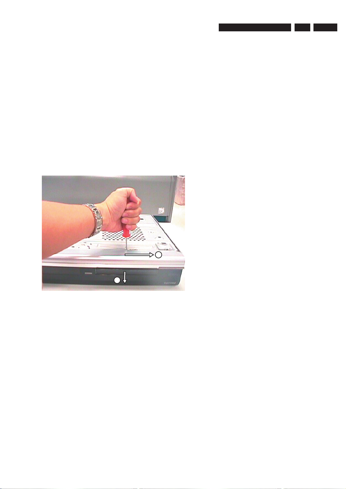
2.2 Open the DVD Tray manually
Note: This procedure needs to be performed on
condition that:
- a customer’s Disc is jammed in the DVD Tray
- the DVD Tray cannot be open via the normal
open/close button on the set.
3139 785 3180x
2.
EN 5
1) Place the set on the table with the bottom faced upwards
2) Insert a screw driver into the slot and open the DVD Tray
as shown below.
by sliding the screw driver in the direction shown.
1
2
Figure 2-1
Page 6

EN 6
3.
3139 785 3180x
Firmware Upgrading & Diagnostic Software
3. Firmware Upgrading & Diagnostic Software
3.1 Firmware Upgrading
A. Preparation to upgrade fi rmware:
1. Unzip the zip-archive fi le
2. Start the CD Burning software and create a new CD project (data disc) with the following settings:
File system : Joliet
Format : MODE 2: CDROM XA
Recording mode : SINGLE SESSION (TRACK-AT-ONCE), FINALIZED CD
Note: Long fi le name is necessary for the preparation of the upgrade disc
3. Place the content of the zip-archive into the root directory of the new CD project.
4. Burn the data onto a blank CDR or CD-RW
B. Procedure to apply the fi rmware upgrade:
1. Hold the <Record> + <Open/Close> buttons down and Power up the set.
2. The tray opens and set will display:
FORCE DL −>…. INSERT DISC
3. Insert the prepared Upgrade CDROM and close the tray.
4. The set will display:
INIT DSC −> ………. SYS VER −> READ FILES …. DOWNLOAD BE
The whole process takes less than 15 minutes
Note: Do not press any buttons or interrupt the mains supply during the upgrading process, otherwise the set may becomes
defective.
5. When the upgrade is completed the tray will open automatically and the set will display:
REMOVE DISC
6. Close the tray and the set will display:
DONE
7 The set will go into Standby mode.
C. How to read out the fi rmware version to confi rm set has been upgraded:
1. Power up the set.
2. Press <System> button on the Remote control and select {Setup} option
3. Press <Right> button to select {System}
4. The set will prompt you about clearing the Time Shift Buffer
5. Select {Yes} and press <OK> button
6. Press <Down> button several times to select {Version info}
7. Press <OK> button
8. The TV connected to the set will display:
(C) PHILIPS 2006 VERSION INFORMATION:
DIF05_8/7028 AN SV11226
BE 43.3.7.9 ASP 1,18,1,10FP
DTTM HW:01020102 DTTM
SW:00040206
SIT7250H-FF5F-S28_F604
20060203-1650 pro sxcplusint
EPG:3.06 DPMS:P_DPM
9. Press <System> button to exit
Page 7

4. Service Flow Chart
4.1 Start Process
Start
Service Flow Chart
3139 785 3180x
4.
EN 7
No
(Press & hold Play button on Front Panel
Is the
complaint
documented ?
Yes
Is it a known
complaint ?
No
Perform built-in Dealer Test
down + Power-up the set)
Does the set
pass the
Dealer Test ?
Pass
Yes
Fail
A
(Verification
Test)
Is it a
Hardware
problem ?
Yes
No
No
No
Is Firmware
solution
available ?
Yes
Upgrade to latest
Firmware
Is the
complaint
solved ?
Yes
- Attached Defect Description Report
and Proof of Purchase.
- Pack defective set
- Store defective set for pick-up
Send refurbished set from pool
stock to Trade / customer
Return set to Customer with
Report on action done
Service W/S to contact the Trade /
Customer to work out an action plan.
Examples:
- explain them that the Firmware
solution is not ready
- Upgrade disc will be send to them the
moment a solution is ready
- etc.
Page 8

EN 8
4.
3139 785 3180x
4.2 Verifi cation Process
Service Flow Chart
A
(Verification
Test)
Connect up the Recorder
to TV antenna, TV set
and an External source
B
Recording
Check
Can the set
Start-up ?
Yes
Check the Firmware
version on the set
Is Firmware the
last released
version ?
Yes
C
Playback
Check
No
No
Upgrade to latest
Firmware
D *
System Menu
Are the
checks result
ok ?
Yes
Return set to Customer with
Report on action done
* If complaint is related to
System Menu setting
No
- Attached Defect Description Report and
Proof of Purchase.
- Pack defective set
- Store defective set for pick-up
Send refurbished set from pool
stock to Trade / customer
Page 9

4.3 Recording Process
A
Manual Recording during TSVB HDD: Manual Recording
Copy to DVD Recordable disc Timer Recording
Service Flow Chart
B
Recording
Check
3139 785 3180x
4.
EN 9
1) Switch the Recorder to Tuner source
- The active Tuner channel will be
recorded into the TSB (time shift
buffer), a temporary HDD storage
area.
2) By pressing the "INFO" button the
Time Shift video bar (TSVB) appears
on the screen, check the following
features:
- search forward / backward
- instant replay, pause, etc. on the
live TV function
Does the
TSB feature
works ?
Yes
1) Make a short recording (stop > 1 minute)
by during Time Shift video bar display.
2) Playback the recorded title from the
HDD browser
Does the
recording
functions ?
Yes
1) Insert a DVD+RW disc
2) In the HDD browser select the recorded
title for copy to recordable DVD
3) From the Disc Menu select the copied
title and check the following:
- edit features
- play the title
4) Repeat with DVD-RW
No
No
Is the Disc
Library feature
working ?
Yes
Make a manual recording to the HDD
using different recording source:
- Cam (DV-in)
- Cam 1 (Front CVBS/S-Video)
- Tuner
- Rear Ext 1/2 (external Cable
Box/Satellite Receiver/VCR/DVD)
From the HDD browser select the
recorded title and check the following:
- edit title feature
- play the title
No
Make a Timer recording with:
- VPS/PDC on and off
- Guide Plus+ System
- Show View System
- manual selection
Playback the recorded title from HDD
browser
No
No
re Timer edit &
delete feature
working ?
Yes
No
Does manual
recording
functions ?
Yes
Does Timer
recording
functions ?
Yes
Continue
Does copy
function ?
Yes
Continue
No
- Attached Defect Description Report and
Proof of Purchase.
- Pack defective set
- Store defective set for pick-up
Send refurbished set from pool
stock to Trade / customer
Page 10

EN 10
4.
4.4 Playback Process
HDD playback Check Disc playback Check
3139 785 3180x
Service Flow Chart
C
Playback
Check
From the HDD browser check the
following features:
- Sorting
- Titles: Delete, Copy & Protect
- Play / Edit features
Does the set
work ?
Yes
Play a title from the HDD browser and
check the following features:
- Pause, Search Fwd/Rev & Next /
Previous chapter
- Editing features
-
No
From the DVD Menu or DVD Browser go
through the Content, Title & Toolbar
options.
Play a DVD video disc title and check the
following:
- Pause, Search Fwd/Rev & Next /
Previous chapter
- Edit features
- T/C search
No
Playing other type of disc:
1) Use discs of DVD PLAYER TEST PACK for:
- (Super) Video CD
- MP3 disc
- Picture disc (slide show)
- special DVD playback check by layer change test u
DVD disc of this package
2) For AUDIO CD use of CD-RW printed Audio Disc to check:
- Track 3 finger print
- Track 8: 600u black dot (max. after 1 min.)
Does the set
work ?
Yes
sing
Does the set
work ?
Yes
No
- Attached Defect Description Report and
Proof of Purchase.
- Pack defective set
- Store defective set for pick-up
Send refurbished set from pool
stock to Trade / customer
No
Does the set
work ?
Yes
ContinueContinue
Page 11

4.5 System Menu
D
System Menu
Check
Toolbar - check the following features:
- Option
Preferences - check the following features:
- Recording
- DV Specials
- Sound
- Disc
- Access
- Features
Service Flow Chart
Does the
set work ?
Yes
3139 785 3180x
No
4.
EN 11
Setup - check the following features:
- System
- Time-date
- Analogue Ch
- Digital Ch
- Video output
- Audio output
- Audio input
- Language
Continue
- Attached Defect Description Report and
Proof of Purchase.
- Pack defective set
- Store defective set for pick-up
Send refurbished set from pool
stock to Trade / customer
Page 12

EN 12
5. Directions For Use
The following except of the Quick Use Guide serves as an introduction to the set.
The Complete Direction for the Use can be downloaded in different languages from the internet site of Philips Customer care Center:
www.p4c.philips.com
HDD & DVD Player / Recorder DVDR7250H
5.
3139 785 3180x
Directions For Use
Quick Start Guide
What’s in the box?
HDD & DVD Player / Recorder
1
2
3
Remote Control
and 2 batteries
Connect
Set up
Enjoy
Tuner interlink cable
RF coaxial cable
Power cable G-LINK cable &
transmitter
User ManualScart cable
Page 13

Connect
1
Basic Connection
Before Connecting
A
Unplug the antenna cable that is currently connected to
your TV.
If you have only a single off-air antenna, follow ‘B1’
connection.
If you have both the off-air antenna and digital terrestrial
antenna, follow ‘B2’ connection.
Connecting
B1
Television ( rear)
Start with the ‘Basic connection’.
If you have a VCR, follow the instructions for ‘Connection with VCR or similar device’.
If you have a set-top box, follow the instructions for ‘Connection with set-top box’.
Directions For Use
Connecting (with digital terrestrial
B2
antenna)
Television (rear)
3139 785 3180x
From an offair antenna or
cable box
5.
EN 13
From an off-air
antenna or
cable box
Philips Recorder (rear)
A Disconnect the antenna cable from your TV and
connect it to the ANTENNA socket on this
recorder.
B Use the supplied RF coaxial cable to connect the TV
socket on this recorder to the Antenna In socket
on the TV.
C Use the supplied Tuner interlink cable to connect
the two ‘A’-sockets on this recorder.
D Use the supplied scart cable to connect the
EXT1 TO TV-I/O scart socket on this recorder to
the SCART IN socket on your TV.
E Plug in the power cable from the recorder to an AC
power outlet
From digital
terrestrial
antenna
Philips Recorder (rear)
A Disconnect the antenna cable from your TV and
connect it to the
B Connect the indoor DVB-T antenna cable to the
ANTENNA socket on this recorder.
C Use the supplied RF coaxial cable to connect the
TV socket on this recorder to the Antenna In
socket on the TV.
D Use the supplied scart cable to connect the
EXT1 TO TV-I/O scart socket on this recorder to
the SCART IN socket on your TV.
E Plug in the power cable from the recorder to an AC
power outlet
socket on this recorder.
Note See the accompanying user manual for other possible connections (e.g. S-Video, Component Video)
Page 14

EN 14
5.
3139 785 3180x
Directions For Use
Connection with VCR or
similar device
Before Connecting
A
Your new Philips Recorder replaces the VCR for your
recording needs. First, unplug all the connections from
your VCR.
Connecting
B
Television ( rear)
From an off-air
antenna or cable box
Connection with set-top box
Your new Philips Recorder provides a G-LINK
transmitter which allows you to control the tuner of the
set-top box (satellite receiver, cable TV box) through
the GUIDE Plus+ system. You can record the TV
programmes that are received through the set-top box.
Connecting
Television ( rear)
Philips Recorder
(rear)
VCR or similar
device (rear)
A Follow step 1 to 5 of ‘Basic connection’ to connect
this recorder before you proceed to step 2 below.
Above illustration shown the connection without
the digital terrestrial antenna.
B Use another scart cable (not supplied) to connect
the EXT2 AUX-I/O scart socket on this recorder to
the SCART OUT socket on your VCR.
C Connect the power cable from the VCR to an AC
power outlet.
Note In this setup, the VCR cannot record TV
programmes.
To source
Set-Top Box (rear)
Positioning of G-LINK
transmitter
Set-top box
G-LINK transmitter
A Follow step 1 to 5 of ‘Basic connection’ to connect
this recorder before you proceed to step 2 below.
Above illustration shown the connection without
the digital terrestrial antenna.
B Connect the supplied G-LINK cable to the G-LINK
socket on this recorder.
C Place the G-LINK transmitter in front of your set-
top box in such a way that it can acquire the signal
broadcasted by the transmitter.
D Connect the power cable from the set-top box to
an AC power cable.
Page 15

2
Set up
Directions For Use
3139 785 3180x
5.
EN 15
Finding the viewing channel
A
A Presss STANDBY-ON on the recorder.
The recorder will display ‘IS THE TV ON?’.
B Turn on the TV.
You should see the { EASY SETUP } menu.
Note If your VCR is connected to this recorder,
ensure it is turned off or in standby before proceeding.
C In case you don’t see the recorder’s setting menu,
press the Channel Down button on the TV’s remote
control repeatedly (or AV, SELECT, ° button) until
you see the menu. This is the correct viewing
channel for the recorder.
Start basic setup
B
Use the recorder’s remote control and follow the onscreen instructions to complete the installation.
A Select the desired menu language, your country and
the TV shape.
Note Select { Done } in the menu and press to go
to the next screen.
B Activate automatic channel search for analogue and
digital tuner/radio.
C Check the date and time and press
D To continue with the GUIDE Plus+ installation,
select { Continue } and press
Otherwise, select { Do not install now } and press
. Wait until the recorder has finished initialising
the system, then press
Install the GUIDE Plus+ system
C
again.
.
.
Install the set-top box
D
If you do not have a set-top box, skip ‘D’ and go to ‘E’.
A Press T down to select ‘External Receiver 1’ and
press
B Press again to continue.
C Select the type of reception, service provider and
brand name of the connected set-top box.
D Select the recorder socket through which your set-
top box is connected (e.g. ‘EXT2’ for EXT2 AUX-I/O
socket) and press .
E Turn on your set-top box and select channel
number 02 on the set-top box.
F Read the instructions on the TV and press .
G If the set-top box has switched to the same
programme number as displayed on the TV, select
{ Yes } in the menu and press
H Your set-top box is now installed. Press the green
E
A Press GUIDE
Leave the recorder in ‘standby’ mode and turn ‘on’
the set-top box overnight to collect the TV listing
data, this may take up to 24 hours.
.
Note Press to go to the next screen. Select
{ None } if none of the entries are applicable.
Setup External Receiver 1
Has the External Receiver 1 changed to
Programme Number 101?
.
Note If not, select { No } and press to try a
different code.
button to exit.
Note To switch the GUIDE Plus+ system’s host
channel manually, go to { Host Channel Setup }.
Load the TV listing data
to exit GUIDE Plus+ system.
Note If you tune to your Host Channel before going
to ‘standby’ mode, this recorder will start downloading
the TV listings data immediately.
A Follow the on-screen instructions to select your
language, country and enter the postal code of your
area.
Note If no or wrong postal code is entered, it will
cause no GUIDE Plus+ (EPG) service information.
B Check the { Editor } screen the next day to ensure
the source and programme numbers are matching
for all channels.
Page 16

EN 16
3
5.
Enjoy
3139 785 3180x
Directions For Use
About the Time Shift Buffer
(TSB)
Once you turn on the recorder, the selected TV
programme will be stored in a temporary hard disk
storage called the ‘TSB’ (Time Shift Buffer). The ‘TSB’
can store up to 6 hours of programmes temporarily.
Press INFO
Start time of the
programme
Selected clips for
recording
The contents in the time shift video bar will be cleared
when you press STANDBY ON (2).
once to display the Time Shift video bar.
Programme
information
21:00
Programmes
stored in the ‘TSB’
Current time of
playback
Note A con rmation message on clearing the Time
Shift Video bar will be appeared if you press the CAM
button on the remote control or access the { Setup }
or { Record mode } option in the setup menu.
23:13
End time of
the buffer
Record to hard disk
Contents in the temporary HDD
A
storage
A Press INFO to view what is temporarily stored
in the hard disk storage.
B Press S up or T down to choose the title you
want to record.
C Press to search for the scene where you want
to start recording, then press the red
Note Pressing the red button again will cancel
the recording.
D Press STOP to end the recording.
Note The title will be marked in red and the
recording will only take effect when you turn off the
recorder.
button.
Watch TV – Pause live TV
Your Philips Recorder allows you to control the TV
programme. You can PAUSE it as if you were in control
of the live broadcast.
A Turn on your recorder and press TUNER to switch
between analogue and digital tuner, then press
CHANNEL +/- to select a TV programme.
B Press PAUSE to suspend it.
C Press PLAY
D Press TUNER to return to the live broadcast.
to continue.
Help text information bar
The help text bar located at the bottom of the screen is
providing the information on:
l remote control keys that can be used at the current
state.
l brief information of the selected item.
Current TV programme
B
A Press REC
to 6 hours.
Note To set the recording time, press repeatedly
to extend the recording time in 30-minute increments,
up to 6 hours. If GUIDE Plus+ system is available,
‘Record 1 program’ is displayed and the current
programme will be recorded.
B To stop the recording before the scheduled time,
press STOP .
to start recording. It can record up
Page 17

Directions For Use
3139 785 3180x
5.
EN 17
Start playback
From the hard disk
A
A Press HDD-BROWSER , then press X right
until you see the { TITLES } and { INFO } menus.
B Press S up or T down to select a title.
C Press PLAY
From a disc
B
A Hold down STOP
Load a disc and close the disc tray.
to start playback.
until the disc tray opens.
Using the GUIDE Plus+ system
Make sure that the analogue tuner installation and TV
listing data download is completed.
Record TV programmes
A Press GUIDE
B Press T down to select a TV channel.
Note Press the yellow button to see an overview
of all the available channels and choose from there.
C Press W left or X right to select a TV programme.
Note Press to go directly to a day before or
the next day TV listings.
D Press the red
programme for recording.
Note You can store up to 25 programmes for
recording.
.
button to set the highlighted
B Press HDD-BROWSER to go to the content
menu. Select { Disc Tray } and press X right until
you see the { TITLES }, { TRACKS } or { PHOTO
ROLLS } menu, depending on the disc type.
C Press S up or T down to select a title.
D Press PLAY to start playback.
Need help?
GUIDE Plus+ system
Go to www.europe.guideplus.com
User Manual
See the user manual that came with your Philips Recorder
Online
Go to www.philips.com/support
GUIDE
2005 © Koninklijke Philips N.V.
All rights reserved.
12 NC 3139 246 19731
www.philips.cocm
 Loading...