

Page 1

Color Television Chassis
Service
Service
2064
Service
ServiceManual
Contents Contents
1. Technical Specifications 00
2. Safety & Maintenance Instructions, Warnings and Notes 00
4. Mechanical Instructions 00
5. Service Modes, Error Codes and Faultfinding 00
7. Electrical Diagrams and PWB's Diagram PWB
Block Diagram Schematic 1
Overall Block Diagram Digital Board 2.1 Chrysalis 2
Wiring Diagram Schematic 3
Display Panel Schematic 4 39
Front Connector Schematic 5 0
Standby Panel Schematic 6 41
Tray Left Panel Schematic 7 43
Tray Right Panel Schematic 8 45
An. Board: Frontend Video Schematic 9 47
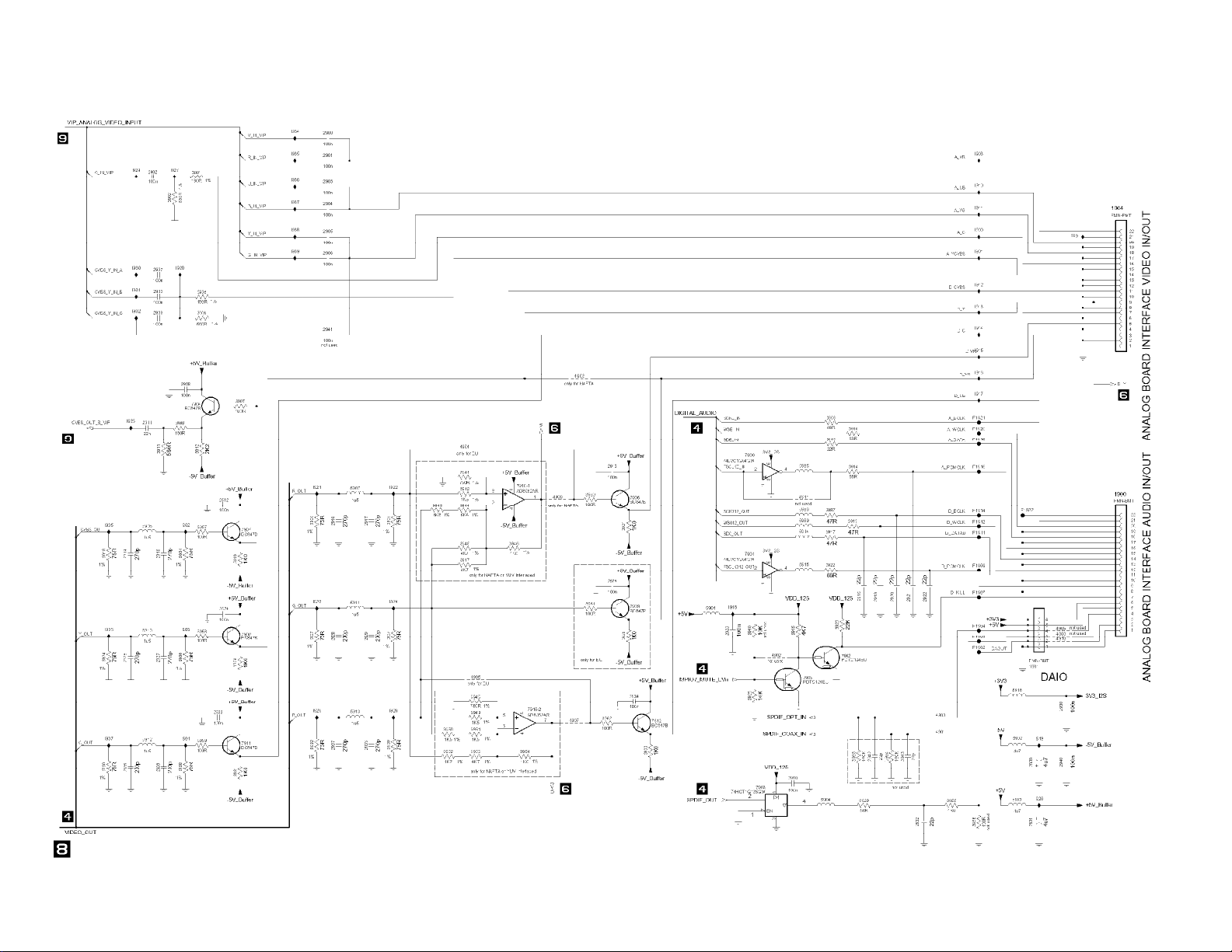
An. Board: In/Out Video Schematic 10 47
An. Board: In/Out Audio Schematic 11 47
An. Board: Power Supply Schematic 12 47
An. Board: Multi Sound Processing Schematic 13 47
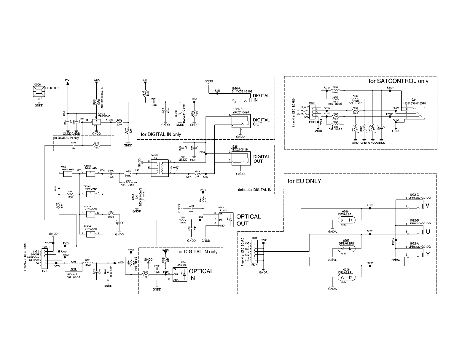
An. Board: Digital In/Out Schematic 14 47
An. Board: Audio Converter Schematic 15 47
UP Sub Board: Central Controller Schematic 16 49
UP Sub Board: Fan Control Schematic 17 49
In/Out Extension Board Schematic 18 51
DVIO Board: 1394 Interface Schematic 19 53
DVIO Board: Link + Codec Schematic 20 53
DVIO Board: uP-Part Schematic 21 53
DVIO Board: Interface + DAC Schematic 22 53
DVIO Board: Clock Schematic 23 53
Dig. Board: VSM, Buffer Memory Schematic 24 54
Dig. Board: AV Decoder STI5519 Schematic 25 54
Dig. Board: AV Decoder Memory Schematic 26 54
Dig. Board: Video Enc. Empress Schematic 27 54
Dig. Board: VIP CVBS Y/C Video Input Schem atic 28 54
Dig. Board: An. Board Cons. Video In/Out Schematic 29 54
Dig. Board: Progressive Scan Schematic 30 54
Dig. Board: Progressive Scan Schematic 31 54
Dig. Board: Power Clock and Reset Audio Schematic 32 54
Digital Board Chrysalis 2.1: IDE, UARTS, RESET, BE 33 72
Digital Board Chrysalis 2.1: 1394 34 72
Digital Board Chrysalis 2.1: Audio PLL 35 72
Digital Board Chrysalis 2.1: Chrysalis 36 72
Digital Board Chrysalis 2.1: 4.8V Power 37 72
Digital Board Chrysalis 2.1: Prog. scan DAC 38 72
Digital Board Chrysalis 2.1: Flash SDRAM EEPROM 39 72
Digital Board Chrysalis 2.1: Video IO 40 72
Digital Board Chrysalis 2.1: VIPs 41 72
Digital Board Chrysalis F: IDE, UARTS, RESET, BE 42 86
Digital Board Chrysalis F: 1394 43 86
Digital Board Chrysalis F: Audio PLL 44 86
Digital Board Chrysalis F: Chrysalis 45 86
Digital Board Chrysalis F: 1.8V Power 46 86
Digital Board Chrysalis F: Prog. Scan Output Filter 47 86
Digital Board Chrysalis F: Flash SDRAM EEPROM 48 86
Digital Board Chrysalis F: Video IO 49 86
Digital Board Chrysalis F: VIPs 50 86
Digital Board Chrysalis F: Faroudja 51 86
Digital Board Chrysalis F: IDE 2 52 86
EPG Board: GS501 RAM, Flash Schematic 53 56
©
Copyrig ht 2001 Philips Consumer Electronics B.V. Eindhoven, The Netherlands.
All rights reser ved. No p art of this p ublication may be reproduced, stored in a
retrieval system or transmitted, in any form or by means, electronic, m echanical,
photographic, or otherwise w ithout the prior permission of Philips.
Published by Philips Consumer Electronics Subject to modification 2005 Nov 02
EPG Board: PIP Codec,Port Expander Schematic 54 56
EPG Board: Controller Schematic 55 56
EPG Board: Power Supply Schematic 56 56
EPG Board: In/Out Schematic 57 56
EPG Board: RGB Converter Schematic 58 56
EPG Board: Glink, Syncsep Schematic 59 56
Layout Display Panel (Top View) 60
Layout Display Panel (Bottom View) 61
Layout Standby Panel (Top View) 62
Layout Standby Panel (Botom View) 63
Layout Tray Left Panel (Top View) 64
Layout Tray Left Panel (Bottom View) 65
Layout Tray Right Panel (Top View) 66
Layout Tray Right Panel (Bottom View) 67
Layout An. Board (Top View) 68
Layout An. Board (Overview Bottom View) 69
Layout UP Sub Board (Top View) 70
Layout UP Sub Board (Bottom View) 71
Layout In/Out Extension Board (Top View) 72
Layout In/Out Extension Board (Bottom View) 73
Layout DVIO Board (Overview Top View) 74
Layout Dig. Board (Overview Top View) 75
Layout Dig. Board (Overview Bottom View) 76
Layout Digital Board Chrysalis 2.1 (Top View) 77
Layout Digital Board Chrysalis 2.1 (Bottom View) 78
Layout Digital Board Chrysalis F (Top View) 79
Layout Digital Board Chrysalis F (Bottom View) 80
Layout EPG Board (Top View) 81
Layout EPG Board (Bottom View) 82
Testpoints Overview An. Board 83
Testpoints Overview UP Sub Board 84
Testpoints Overview DVIO Board 85
Testpoints Overview Dig. Board 86
Testpoints Overview EPG Board 87
8. Adjustments 00
9. Circuit Description 00
10. Spare Parts List 00
Diagram PWB
Page 2

Digital Board Chrysalis 2.1
The Digital Board Chrysalis 2.1_N1 replaces Digital Board 1.5 Empress and
DVIO 1.8 board in DVDR75/17. In this update the circuit diagrams, print layout,
block diagram and the associated parts list are added.
Digital Board Chrysalis F
The Digital Board Chrysalis NF2 replaces Digital Board 1.5 Empress and DVIO
1.8 board in DVDR80/17. Added DVDR72/17. In this update the circuit
diagrams, print layout, block diagram and the associated parts list are added.
DVDR72/17, DVDR75/17 and DVDR80/17
Note that models DVDR72/17 and DVDR75/17 are essentially identical, so when
servicing DVDR72/17, refer to the DVDR75/17 service information.
The DVD+RW Module Basic Engines (VAE8015 and VAE8020) used with the
above models are covered in service manual 2065. Refer to manual 2065 for all
Basic Engine information.
Page 3
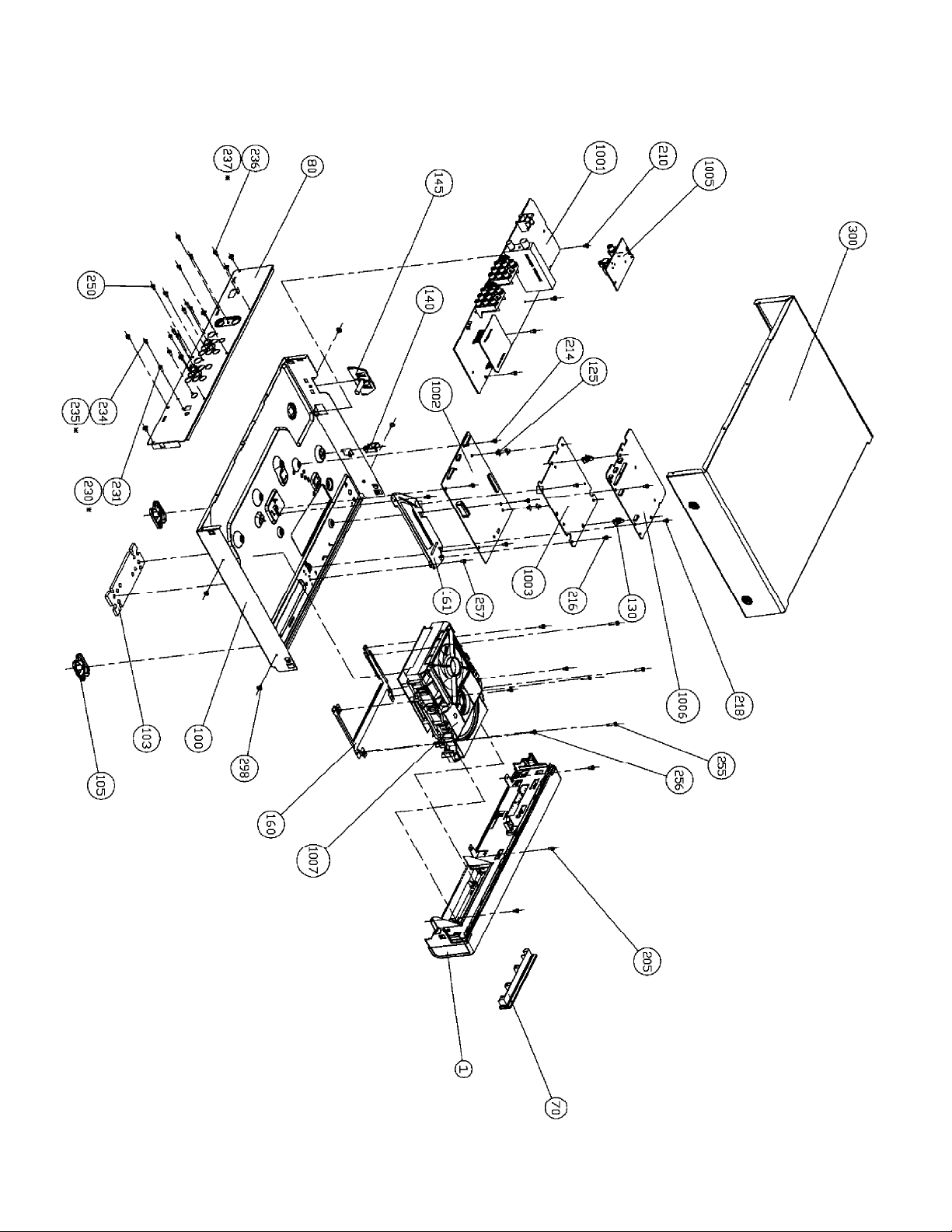
Exploded View of the Set
Page 4
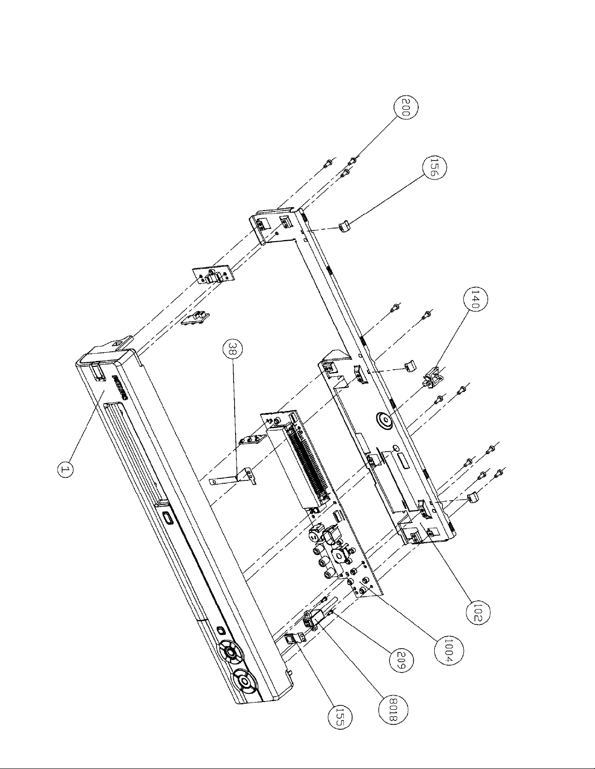
Exploded View of the Front Panel Complete
Page 5
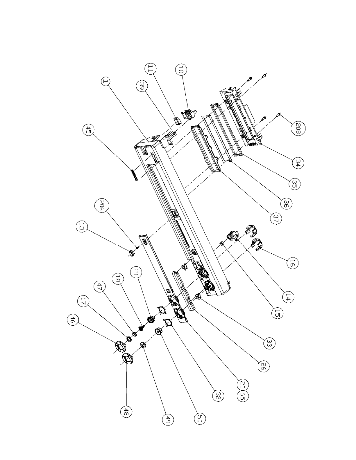
Exploded View of the Front without PWBs
Page 6
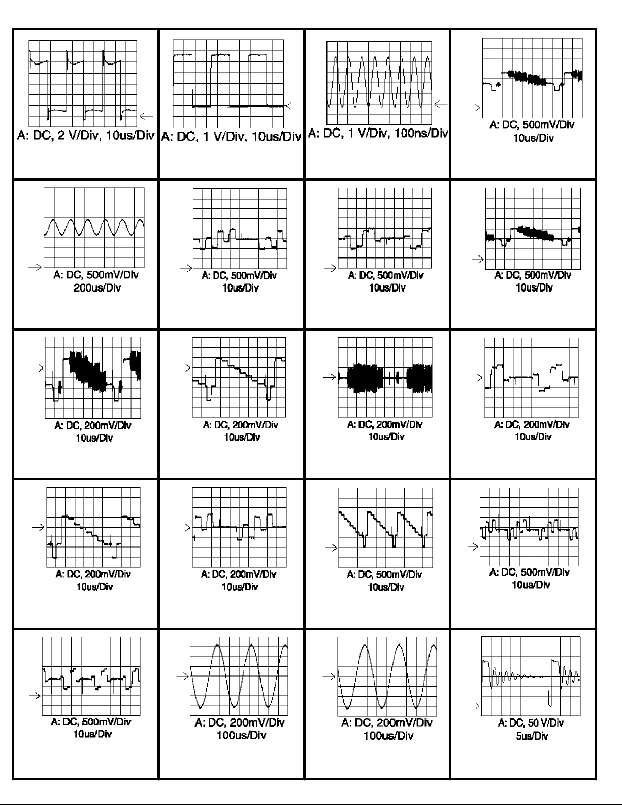
(2064)
)
7106/7108-Emitter IC7103-19 IC7103-8 VID_OUT I701
AMCO I705 Uout I463 Vout I462 A_YCVBS F4709
D_CVBS F4712 D_Y F4714 D_C F4716 D_VR F4718
D_YG F4720 D_UB F4722 Y I419 U I405
V I402 I502/I504 I517/I529 Vdrain F327 (Standby) (110V
Page 7
(2064)
V
Vdrain F327 (No Disc) (110V)VGate I324 (Standby) (110V)VGate I324 (No Disc) (110V)Vsource I325 (Standby) (110
Vsource I325 (No Disc) (110VI014/I032 ARDAC/ALDAC F010/F011 F410
F411 F400/F401 F800 F801
F527 F529 F551 F552
F536 F603 F610 F609
Page 8
(2064)
F620 acc_aclk_pll VSM_M_CLK Sysclk_VSM
R_OUT G_OUT B_OUT CVBS_OUT
Y_OUT C_OUT EMI_PROCCLK Sysclk_5505
I401 VIP_VS VIP_ICKL AD_WCLK; AE_WCLK AD_BCLK; AE_BCLK
AD_ACLK AD_DATAO; AE_DATAO; AE_DATAIAD_SPDIF R_OUT
Page 9
(2064)
G_OUT B_OUT CVBS_OUT Y_OUT
C_OUT Y_OUT; Cr_OUT; Cb_OUT HS_IN VS_IN
DAC-B DAC-A/Y DAC-C HSOUT
VSOUT I215 I216 I217
I218 I232 I402 I403
Page 10
(2064)
I408 I409 I414 I415
I522 I525 I527 A_YCVBS F5109
D_CVBS F5112 D_Y F5114 D_C F5116 D_V F5118
D_Y F5120 D_U F5122 E_Y F5302 U F5304
V F5306 F5002, V F5003, U F5004, Y
Page 11
(2064)
F604, Guide on F605, Guide on F606 F607, CSYNC
F600, Guide on F601, Guide on F602, Guide on F603, Guide on
F702, HSYNC F703, VSYNC I818 A_CVBS F8008
SYNC F843 I623 I618/I619 A_YCVBS F4709
D_CVBS F4712 D_Y F4714 D_C F4716 D_VR F4718
Page 12
(2064)
D_YG F4720 D_UB F4722 AD_WCLK; AE_WCLK AD_BCLK; AE_BCLK
AD_ACLK A_YCVBS F4709 D_CVBS F4712 D_Y F4714
D_C F4716 D_VR F4718 D_YG F4720 D_UB F4722
IC7703 pin 34 IC7703 pin 36 HS_IN Y 1704-2
PB 1704-4 PR 1704-6 IC7402 pin 3, F405 IC7200 pin 60, F203
Page 13
(2064)
X1001 A_YCVBS 1904-14 D_YCVBS 1904-11 D_Y 1904-9
IC7501 pin 5 IC7501 pin 6 IC7703 pin 25 D_C 1904-7
D_VR 1904-5 D_YG 1904-3 VS_IN 1704-2, F1702
IC7703 pin 32 D_UB 1904-1 IC7200 pin 60, F203 HS_IN
VS_IN IC7402 pin 3, F405 IC7501 pin 5 IC7501 pin 6
Page 14
(2064)
Y 1704-2 PR 1704-6 IC7005 pin 173 Y_FAROUDJAPB 1704-4
IC7005 pin 170 PB_FAROUDJAIC7005 pin 176 PR_FAROUDJAA_YCVBS 1904-14 D_YCVBS 1904-11
D_Y 1904-9 D_C 1904-7 D_VR 1904-5 D_YG 1904-3
D_UB 1904-1 X1001 IC7005 pin 170 PB_FAROUDJAIC7005 pin 173 Y_FAROUDJA
IC7005 pin 176 PR_FAROUDJA
Page 15
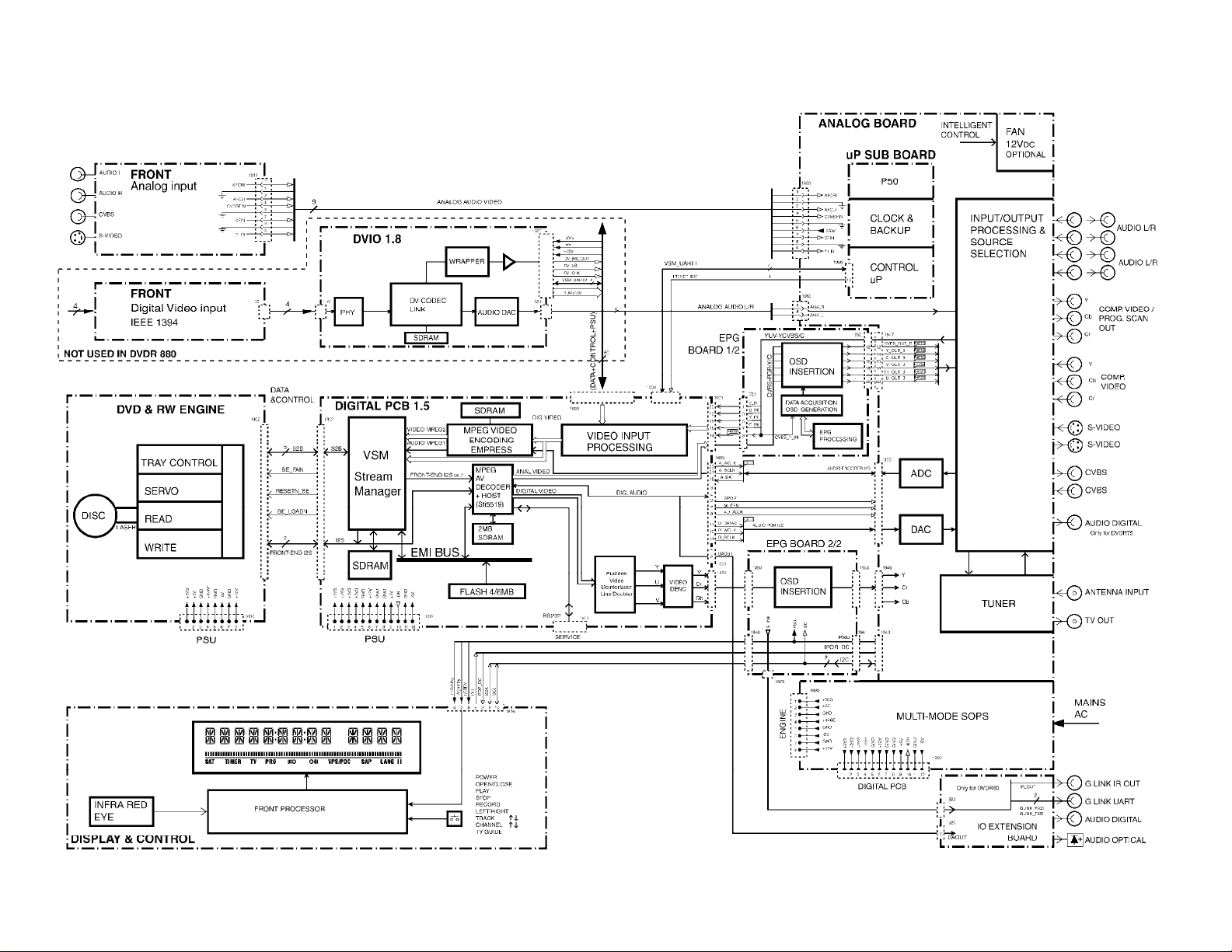
All Models (2064) - Block Diagram Schematic
Page 16
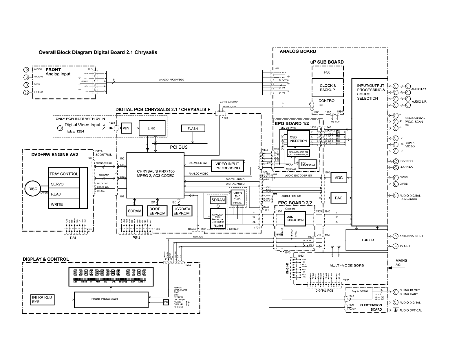
All Models (2064) - Overall Block Diagram Digital Board 2.1 Chrysalis
Page 17
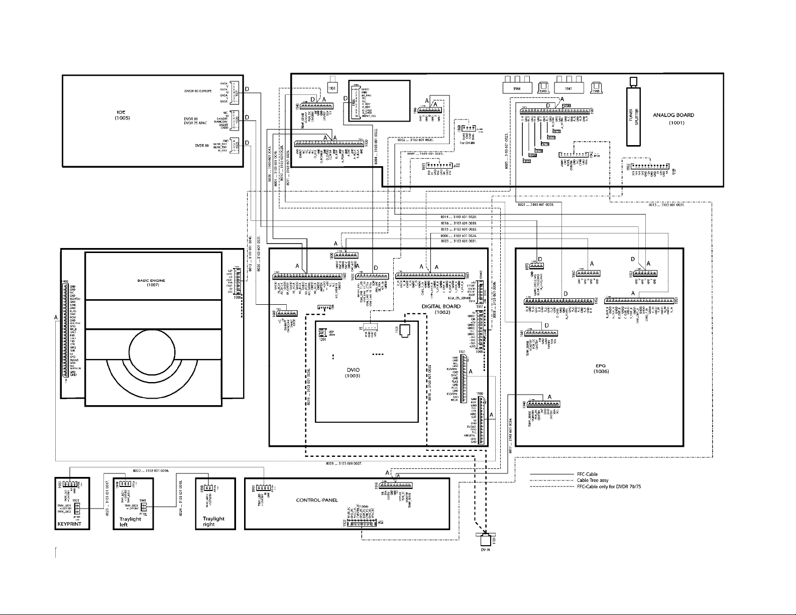
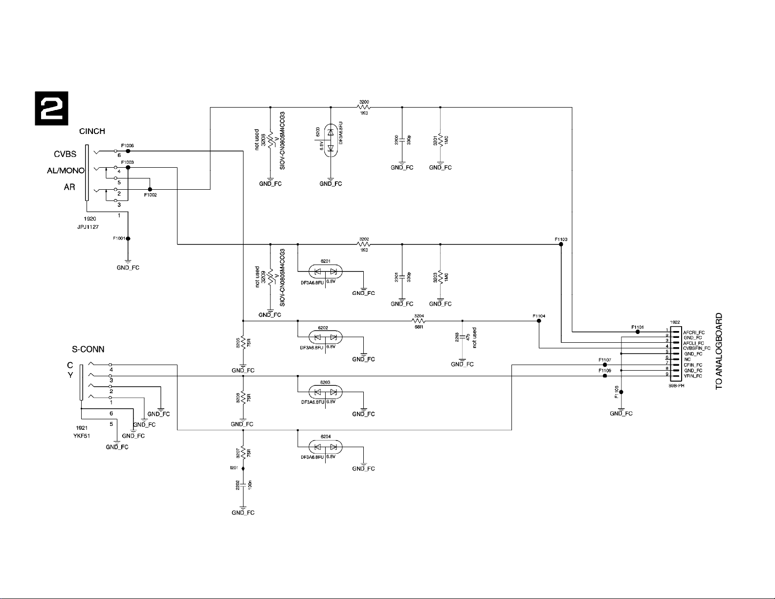
All Models (2064) - Wiring Diagram Schematic
Page 18
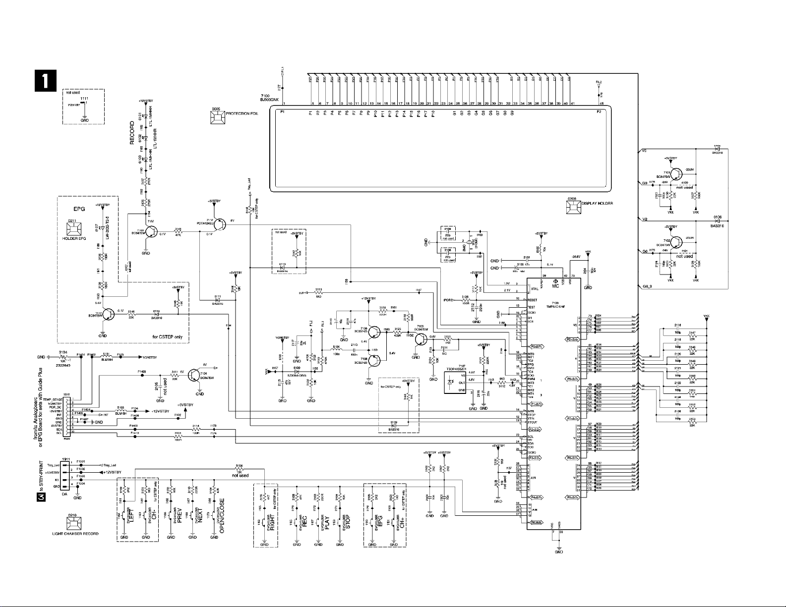
All Models (2064) - Display Panel Schematic
Page 19
All Models (2064) - Front Connector Schematic
Page 20
All Models (2064) - Standby Panel Schematic
Page 21
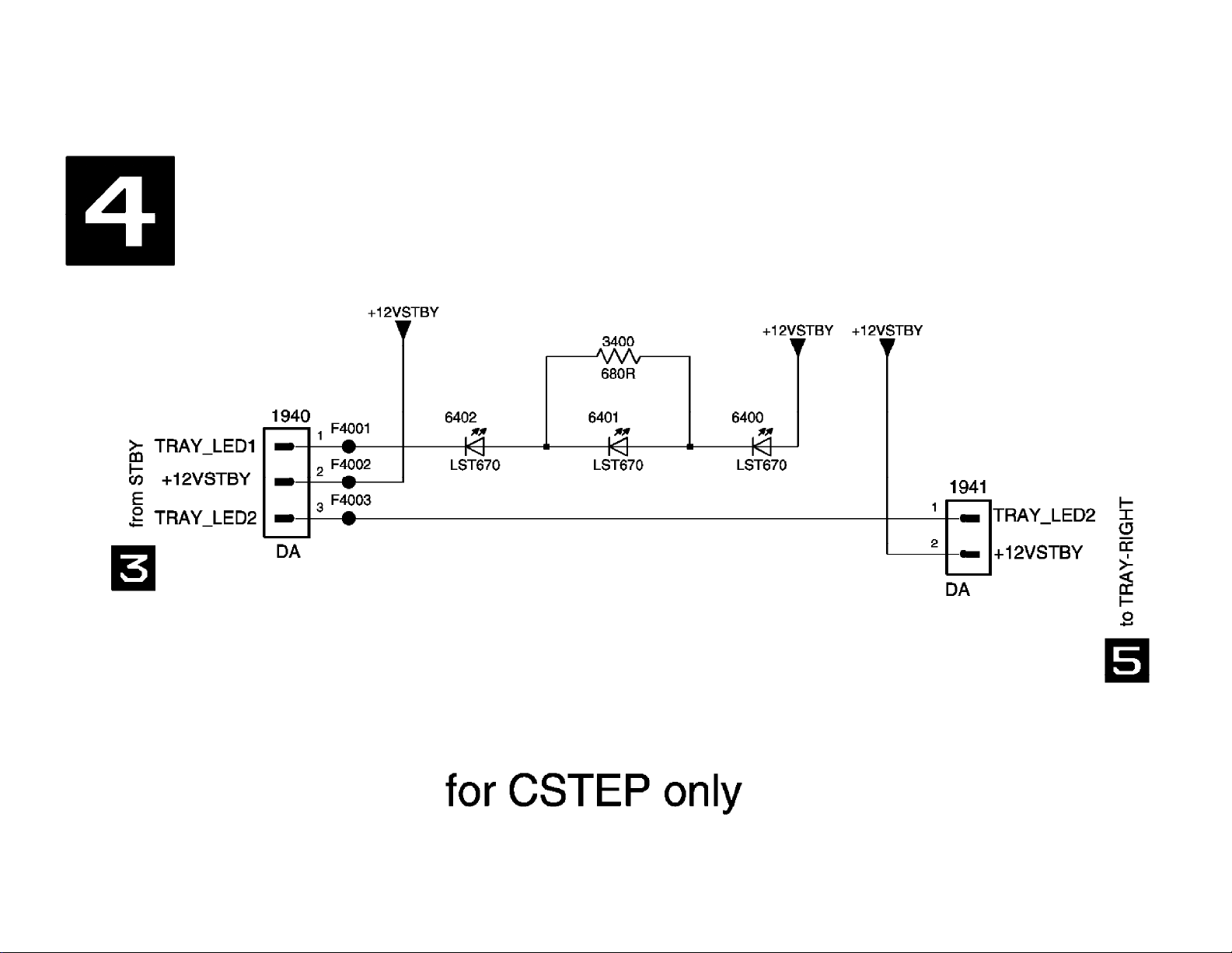
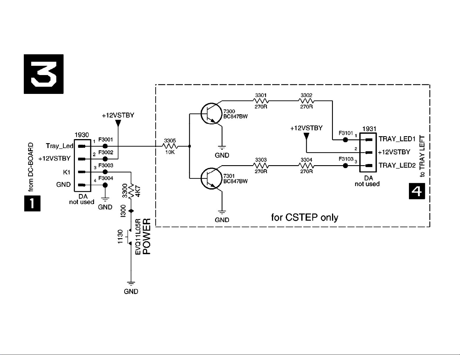
All Models (2064) - Tray Left Panel Schematic
Page 22
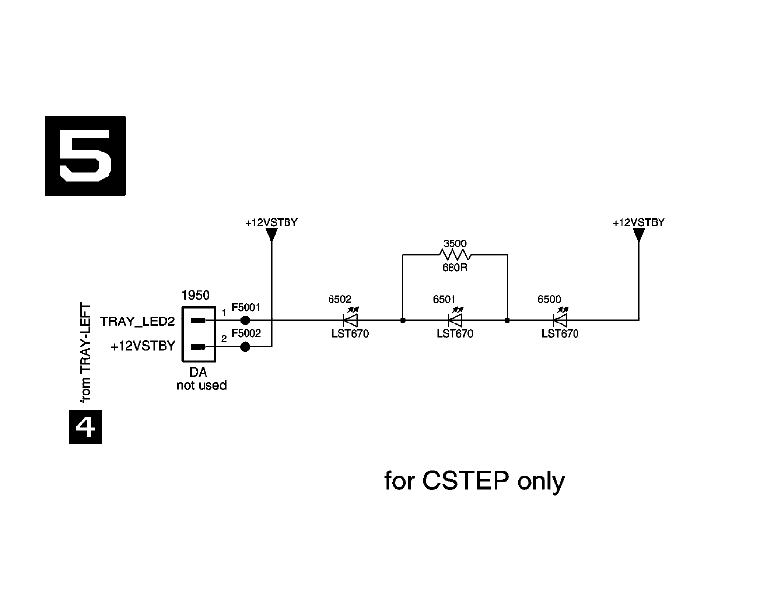
All Models (2064) - Tray Right Panel Schematic
Page 23
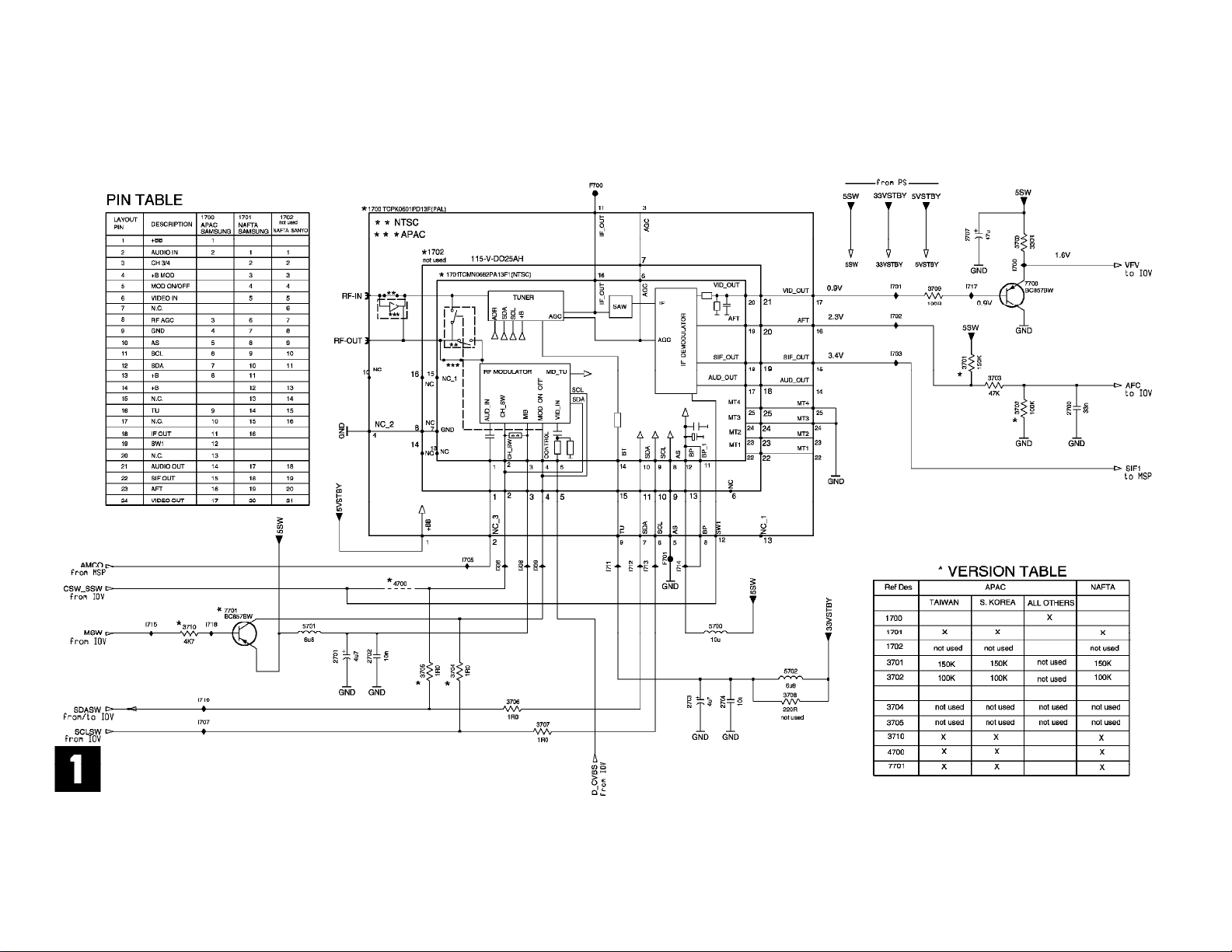
All Models (2064) - An. Board: Frontend Video Schematic
Page 24
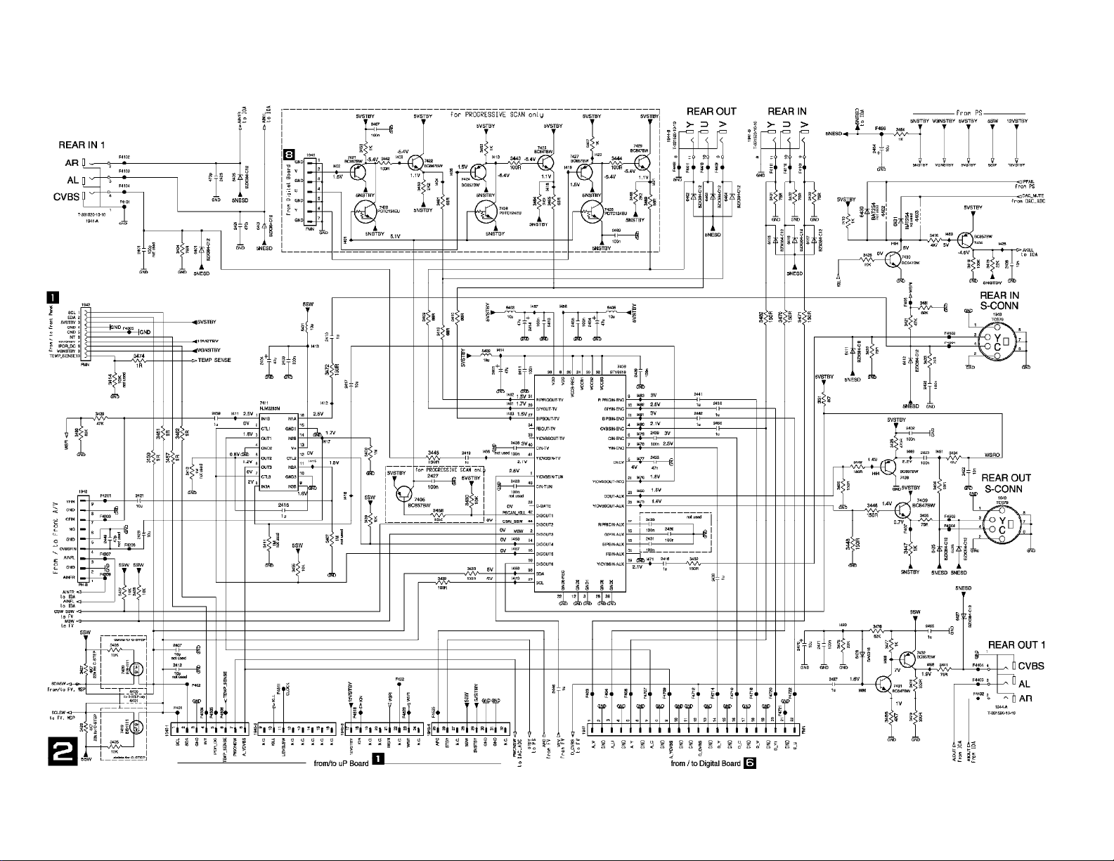
All Models (2064) - An. Board: In/Out Video Schematic
Page 25
All Models (2064) - An. Board: In/Out Audio Schematic
Page 26
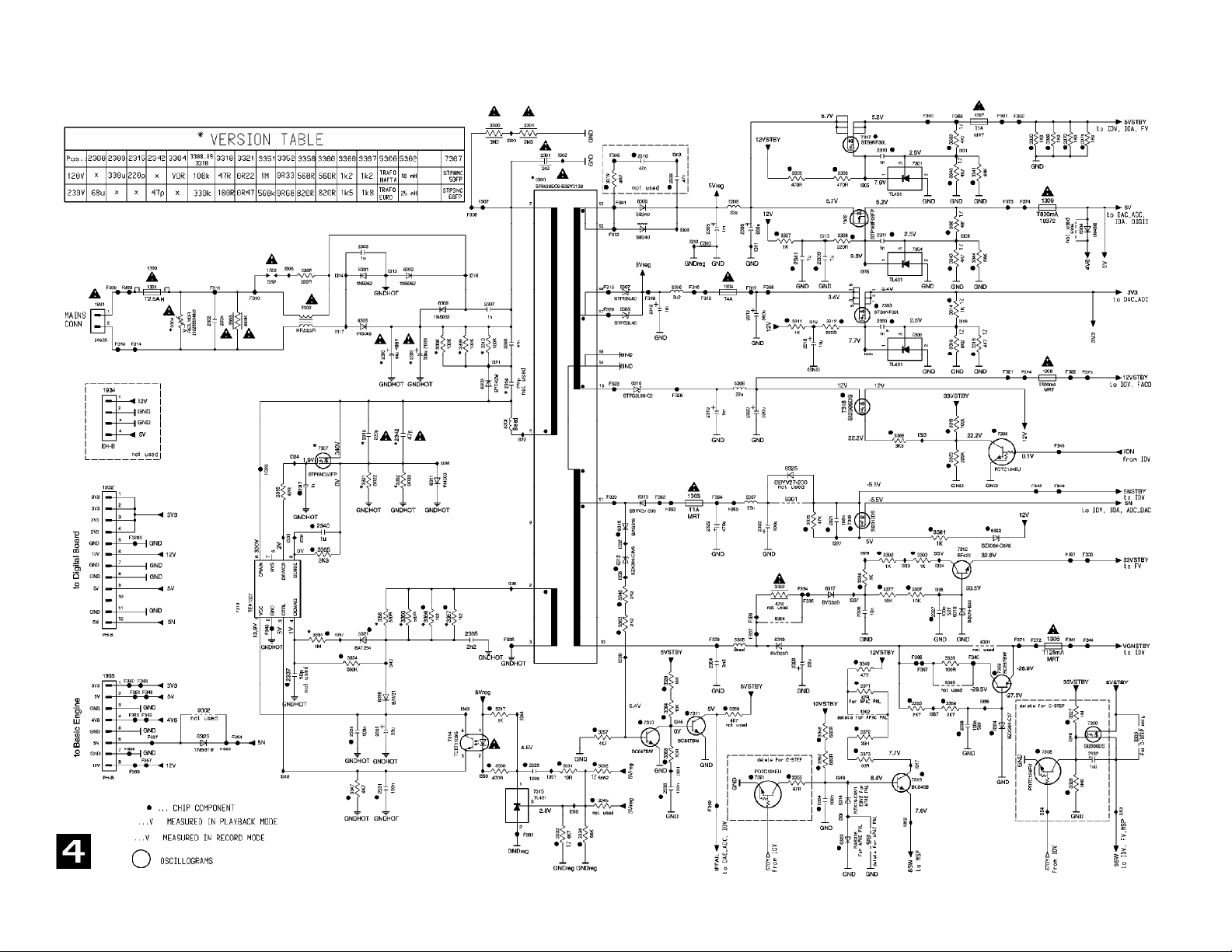
All Models (2064) - An. Board: Power Supply Schematic
Page 27
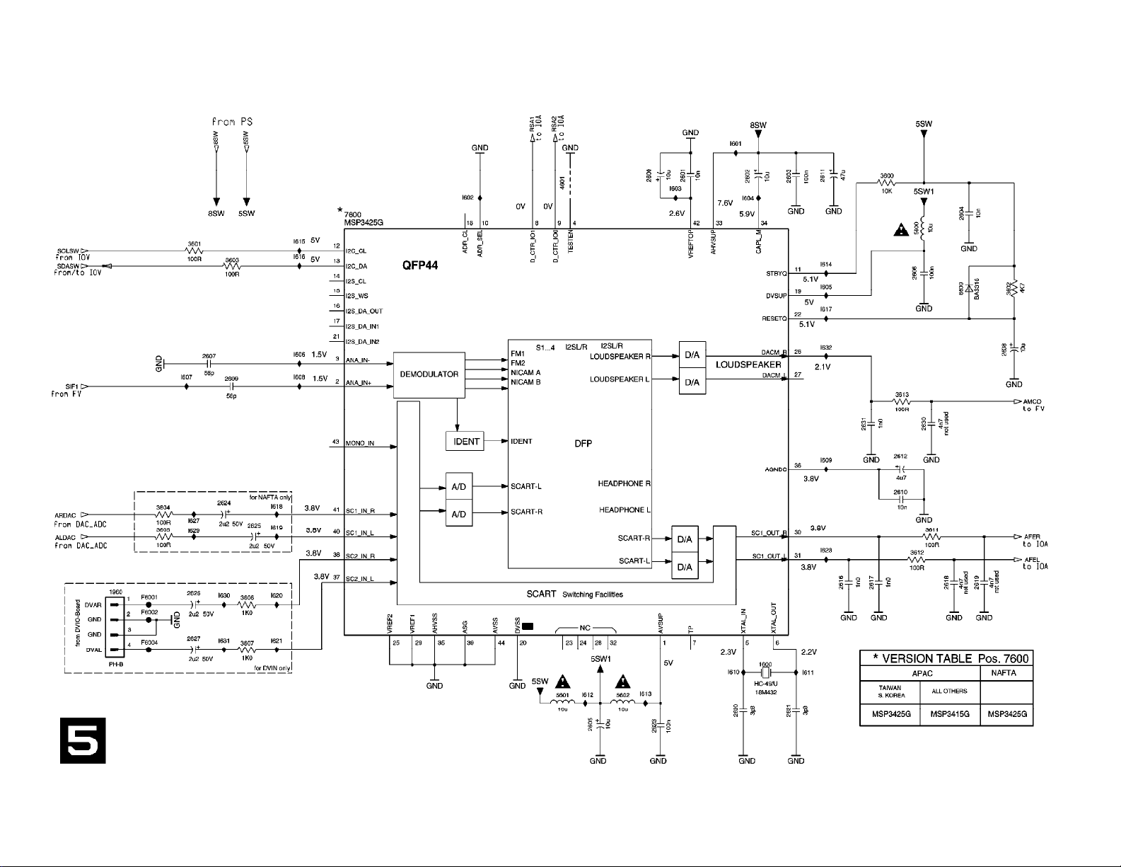
All Models (2064) - An. Board: Multi Sound Processing Schematic
Page 28
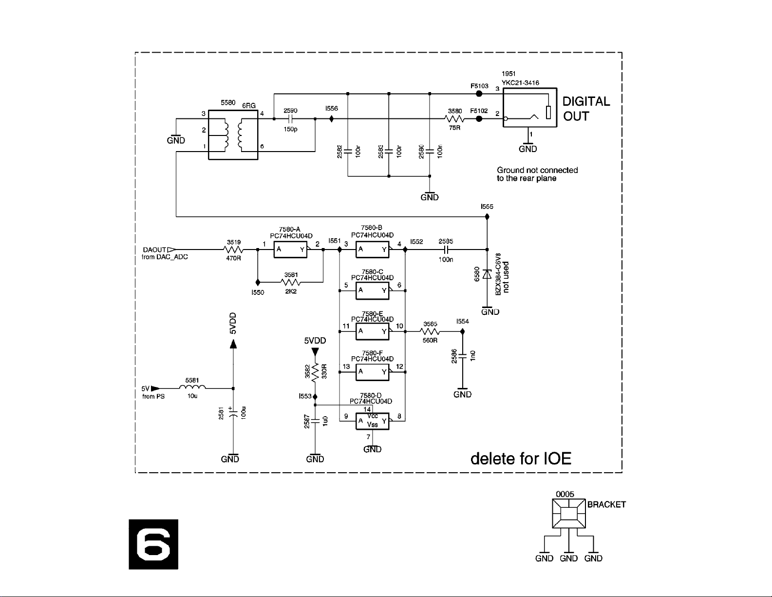
All Models (2064) - An. Board: Digital In/Out Schematic
Page 29
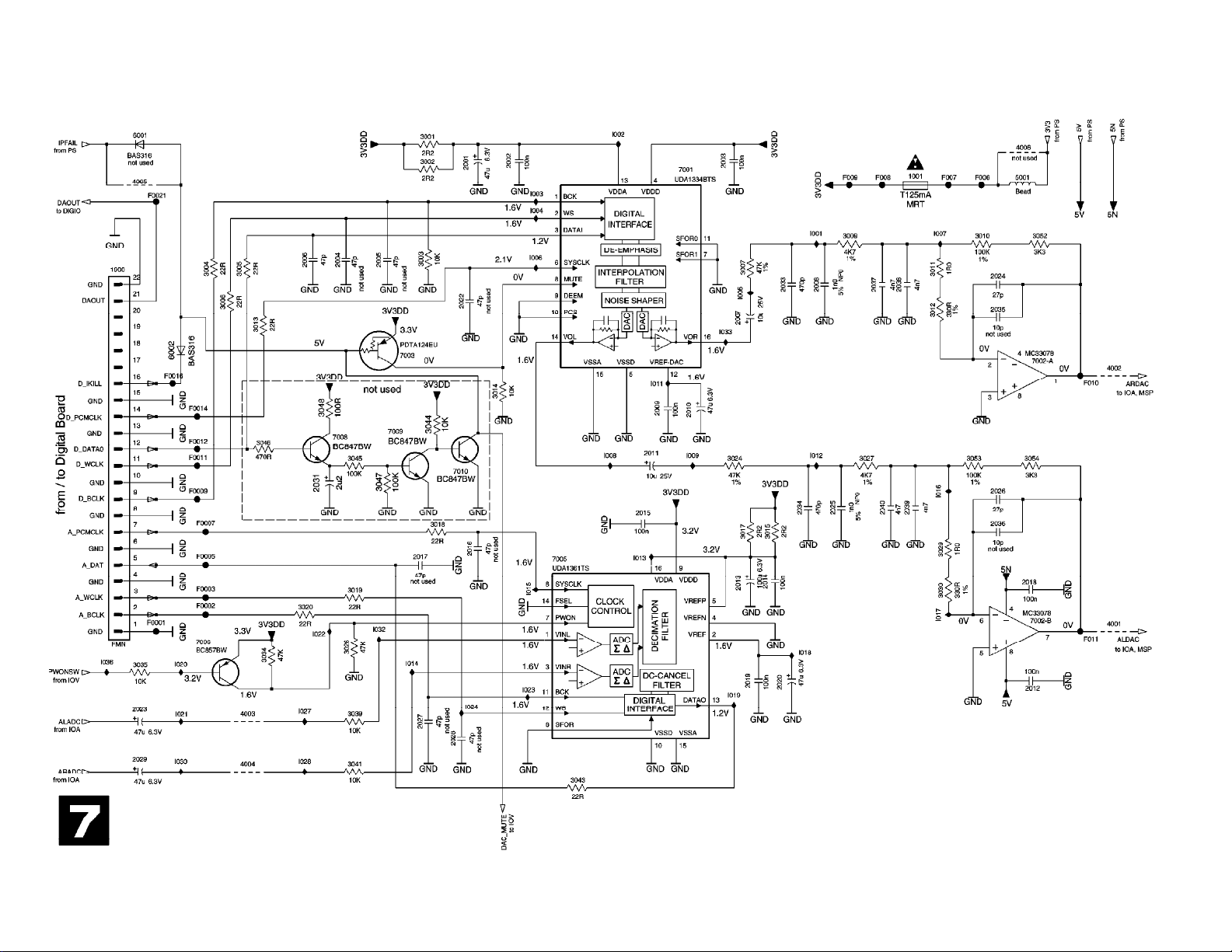
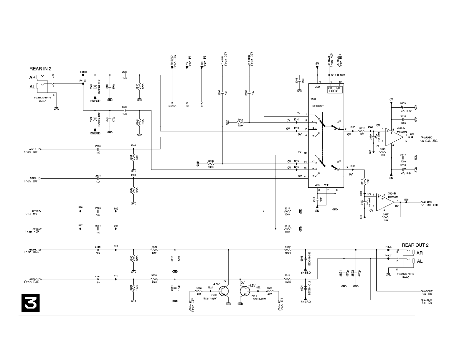
All Models (2064) - An. Board: Audio Converter Schematic
Page 30
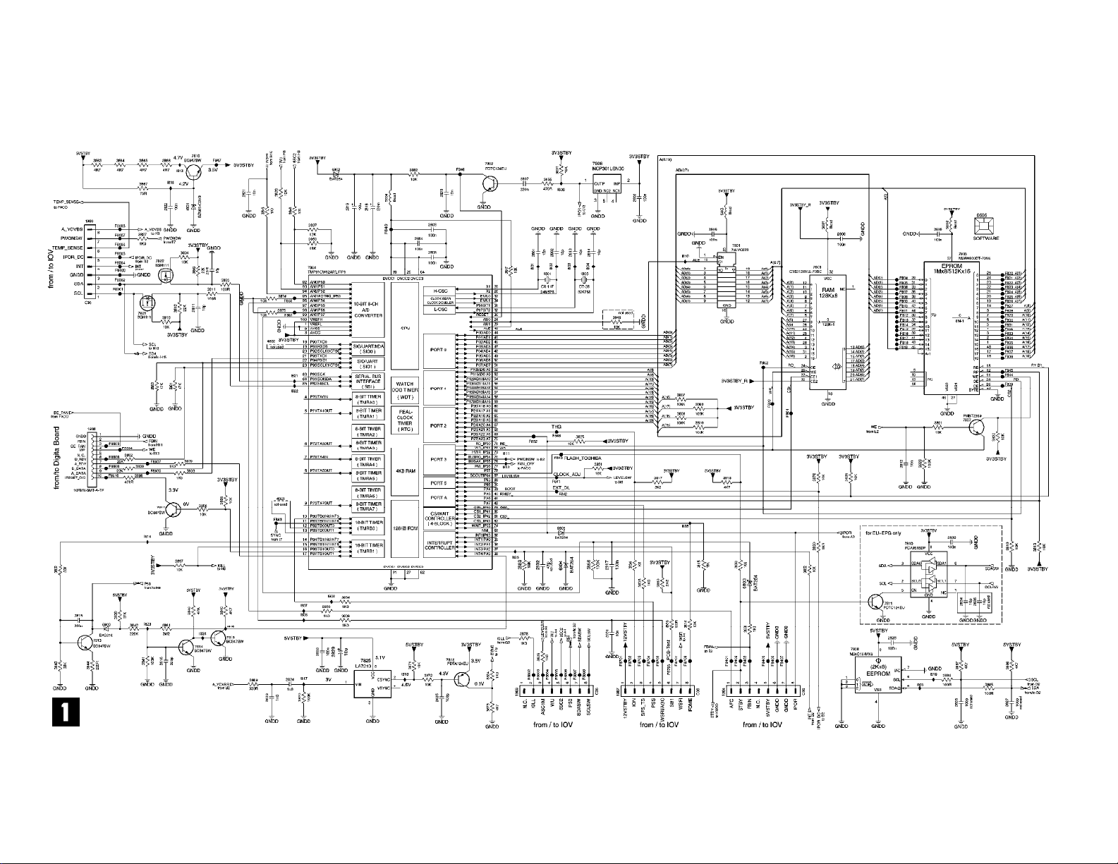
All Models (2064) - UP Sub Board: Central Controller Schematic
Page 31

All Models (2064) - UP Sub Board: Fan Control Schematic
Page 32
All Models (2064) - In/Out Extension Board Schematic
Page 33

All Models (2064) - DVIO Board: 1394 Interface Schematic
Page 34

All Models (2064) - DVIO Board: Link + Codec Schematic
Page 35

All Models (2064) - DVIO Board: uP-Part Schematic
Page 36

All Models (2064) - DVIO Board: Interface + DAC Schematic
Page 37

All Models (2064) - DVIO Board: Clock Schematic
Page 38

All Models (2064) - Dig. Board: VSM, Buffer Memory Schematic
Page 39

All Models (2064) - Dig. Board: AV Decoder STI5519 Schematic
Page 40

All Models (2064) - Dig. Board: AV Decoder Memory Schematic
Page 41

All Models (2064) - Dig. Board: Video Enc. Empress Schematic
Page 42

All Models (2064) - Dig. Board: VIP CVBS Y/C Video Input Schematic
Page 43

All Models (2064) - Dig. Board: An. Board Cons. Video In/Out Schematic
Page 44

All Models (2064) - Dig. Board: Progressive Scan Schematic
Page 45

All Models (2064) - Dig. Board: Progressive Scan Schematic
Page 46

All Models (2064) - Dig. Board: Power Clock and Reset Audio Schematic
Page 47

All Models (2064) - Digital Board Chrysalis 2.1: IDE, UARTS, RESET, BE
Page 48

All Models (2064) - Digital Board Chrysalis 2.1: 1394
Page 49

All Models (2064) - Digital Board Chrysalis 2.1: Audio PLL
Page 50

All Models (2064) - Digital Board Chrysalis 2.1: Chrysalis
Page 51

All Models (2064) - Digital Board Chrysalis 2.1: 4.8V Power
Page 52

All Models (2064) - Digital Board Chrysalis 2.1: Prog. scan DAC
Page 53

All Models (2064) - Digital Board Chrysalis 2.1: Flash SDRAM EEPROM
Page 54

All Models (2064) - Digital Board Chrysalis 2.1: Video IO
Page 55

All Models (2064) - Digital Board Chrysalis 2.1: VIPs
Page 56

All Models (2064) - Digital Board Chrysalis F: IDE, UARTS, RESET, BE
Page 57

All Models (2064) - Digital Board Chrysalis F: 1394
Page 58

All Models (2064) - Digital Board Chrysalis F: Audio PLL
Page 59

All Models (2064) - Digital Board Chrysalis F: Chrysalis
Page 60

All Models (2064) - Digital Board Chrysalis F: 1.8V Power
Page 61

All Models (2064) - Digital Board Chrysalis F: Prog. Scan Output Filter
Page 62

All Models (2064) - Digital Board Chrysalis F: Flash SDRAM EEPROM
Page 63
All Models (2064) - Digital Board Chrysalis F: Video IO
Page 64

All Models (2064) - Digital Board Chrysalis F: VIPs
Page 65

All Models (2064) - Digital Board Chrysalis F: Faroudja
Page 66

All Models (2064) - Digital Board Chrysalis F: IDE 2
Page 67

All Models (2064) - EPG Board: GS501 RAM, Flash Schematic
Page 68

All Models (2064) - EPG Board: PIP Codec,Port Expander Schematic
Page 69

All Models (2064) - EPG Board: Controller Schematic
Page 70

All Models (2064) - EPG Board: Power Supply Schematic
Page 71

All Models (2064) - EPG Board: In/Out Schematic
Page 72

All Models (2064) - EPG Board: RGB Converter Schematic
Page 73

All Models (2064) - EPG Board: Glink, Syncsep Schematic
Page 74

All Models (2064) - Layout Display Panel (Top View)
Page 75

All Models (2064) - Layout Display Panel (Bottom View)
Page 76

All Models (2064) - Layout Standby Panel (Top View)
Page 77

All Models (2064) - Layout Standby Panel (Botom View)
Page 78

All Models (2064) - Layout Tray Left Panel (Top View)
Page 79

All Models (2064) - Layout Tray Left Panel (Bottom View)
Page 80

All Models (2064) - Layout Tray Right Panel (Top View)
Page 81

All Models (2064) - Layout Tray Right Panel (Bottom View)
Page 82
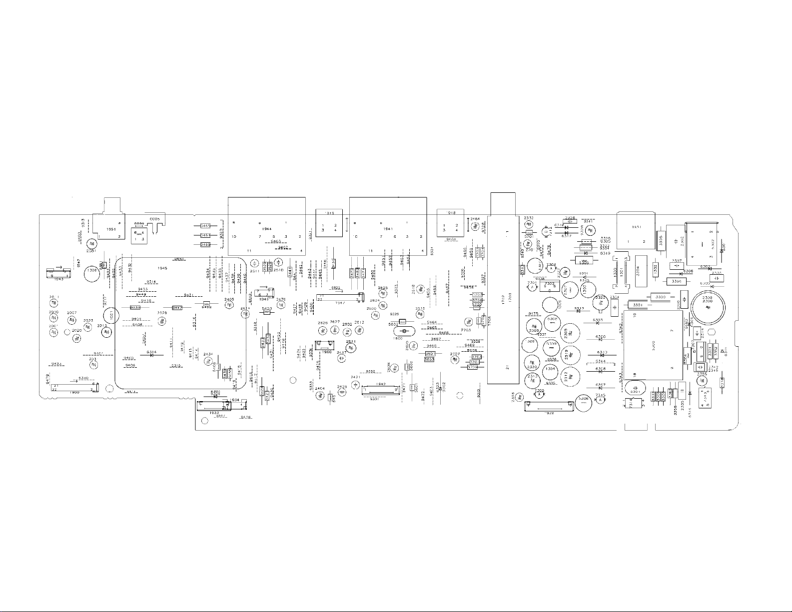
All Models (2064) - Layout An. Board (Top View)
Page 83

All Models (2064) - Layout An. Board (Overview Bottom View)
Page 84

All Models (2064) - Layout UP Sub Board (Top View)
Page 85

All Models (2064) - Layout UP Sub Board (Bottom View)
Page 86

All Models (2064) - Layout In/Out Extension Board (Top View)
Page 87

All Models (2064) - Layout In/Out Extension Board (Bottom View)
Page 88

All Models (2064) - Layout DVIO Board (Overview Top View)
Page 89

All Models (2064) - Layout Dig. Board (Overview Top View)
Page 90

All Models (2064) - Layout Dig. Board (Overview Bottom View)
Page 91

All Models (2064) - Layout Digital Board Chrysalis 2.1 (Top View)
Page 92

All Models (2064) - Layout Digital Board Chrysalis 2.1 (Bottom View)
Page 93

All Models (2064) - Layout Digital Board Chrysalis F (Top View)
Page 94

All Models (2064) - Layout Digital Board Chrysalis F (Bottom View)
Page 95

All Models (2064) - Layout EPG Board (Top View)
Page 96

All Models (2064) - Layout EPG Board (Bottom View)
Page 97

All Models (2064) - Testpoints Overview An. Board
Page 98

All Models (2064) - Testpoints Overview UP Sub Board
Page 99

All Models (2064) - Testpoints Overview DVIO Board
Page 100

All Models (2064) - Testpoints Overview Dig. Board
 Loading...