

Page 1
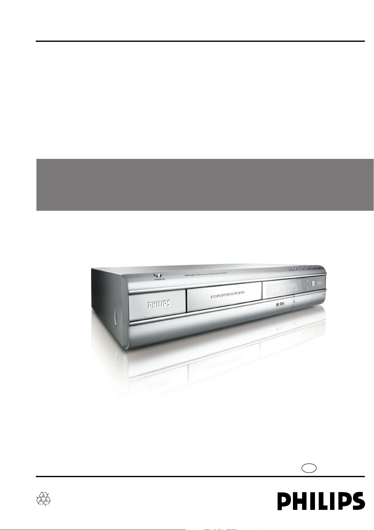
Service Manual
HDD / DVD Recorder Combi
Service
Service
Service
DVDR520H/00/02/04/05/37/69/75/93/97
©
Copyright 2004 Philips Consumer Electronics B.V. Eindhoven, The Netherlands
All rights reserved. No part of this publication may be reproduced, stored in a retrieval system or
transmitted, in any form or by any means, electronic, mechanical, photocopying, or otherwise
without the prior permission of Philips.
Published by LO-MF AV System Printed in The Netherlands Subject to modification
Version 1.3
GB
3139 785 30853
Page 2

CONTENTS
1. Specifications ..............................................................................................1-1
2. Product Validation Strategies and Process
2.1 System Block Diagram ........................................................................2-1
2.3 Front Panel ..........................................................................................2-2
2.4 Rear Panel........................................................................................... 2-2
3. Fault Finding Tree & Trouble shooting ........................................................ 3-1
4 Disassembly Instructions
5.1 Disassemble the Top Cover ................................................................. 3-1
5.1 Disassemble the Drive .........................................................................3-1
5.1 Disassemble the HDD .........................................................................3-1
5.1 Disassemble the M/B ...........................................................................3-1
5.1 Disassemble the Power Module .......................................................... 3-1
5.1 Disassemble the Tuner ........................................................................3-1
5.1 Jumper Setting.....................................................................................3-1
5. Firmware Update ........................................................................................5-1
6. Exploded View & Spare parts list
Exploded view for /37/97 ............................................................................. 6-1
Exploded view for /00/02/04/05/69/75 .........................................................6-2
DVD Test disc & Service parts list ............................................................... 6-3
7. Revision List................................................................................................7-1
Page 3
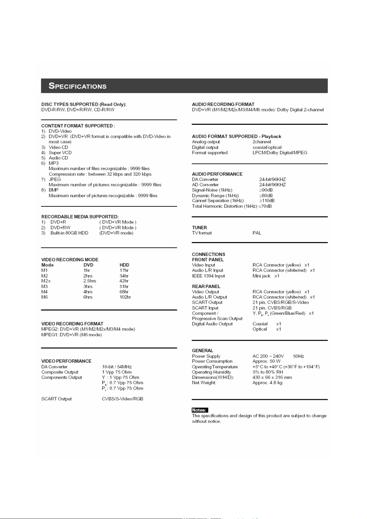
1. Specifications
1-1
Page 4
2-1
2. Product Validation Strategies and Process
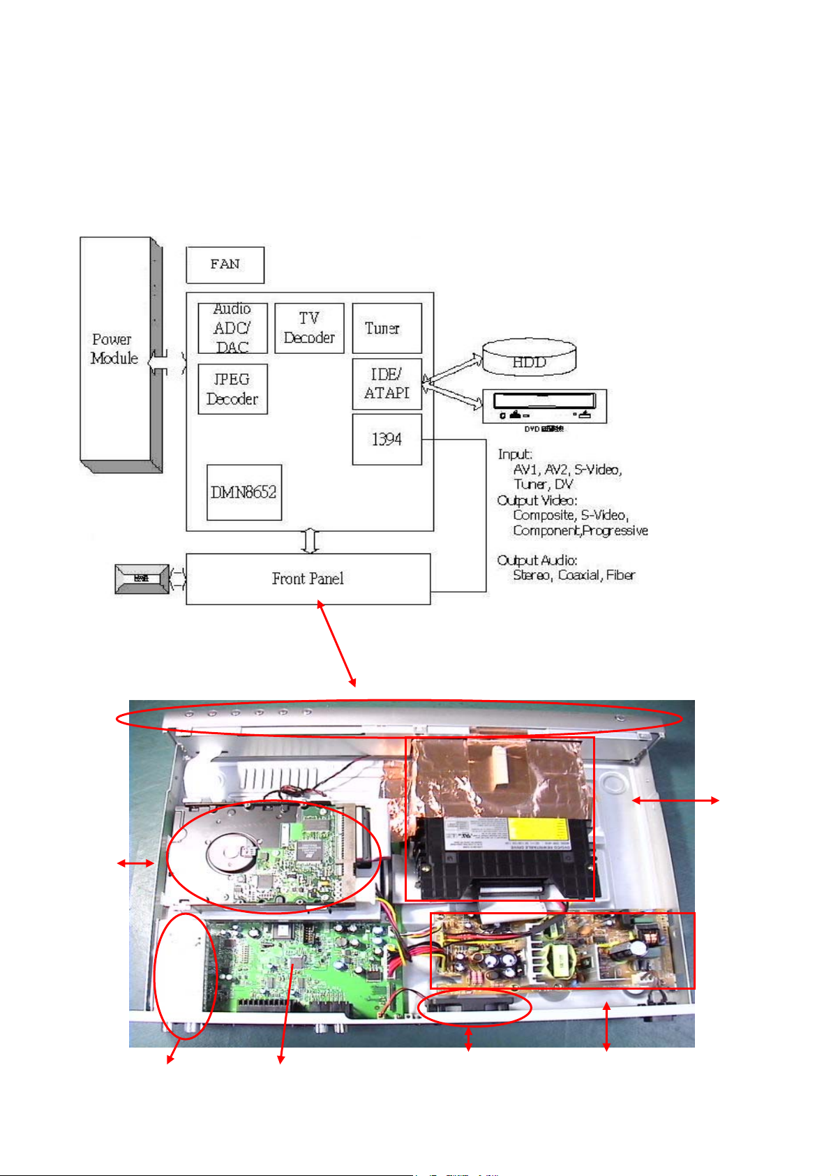
2.1. System Block Diagram
HDD
DVD
M/B Tuner
FAN
Power
Module
Page 5
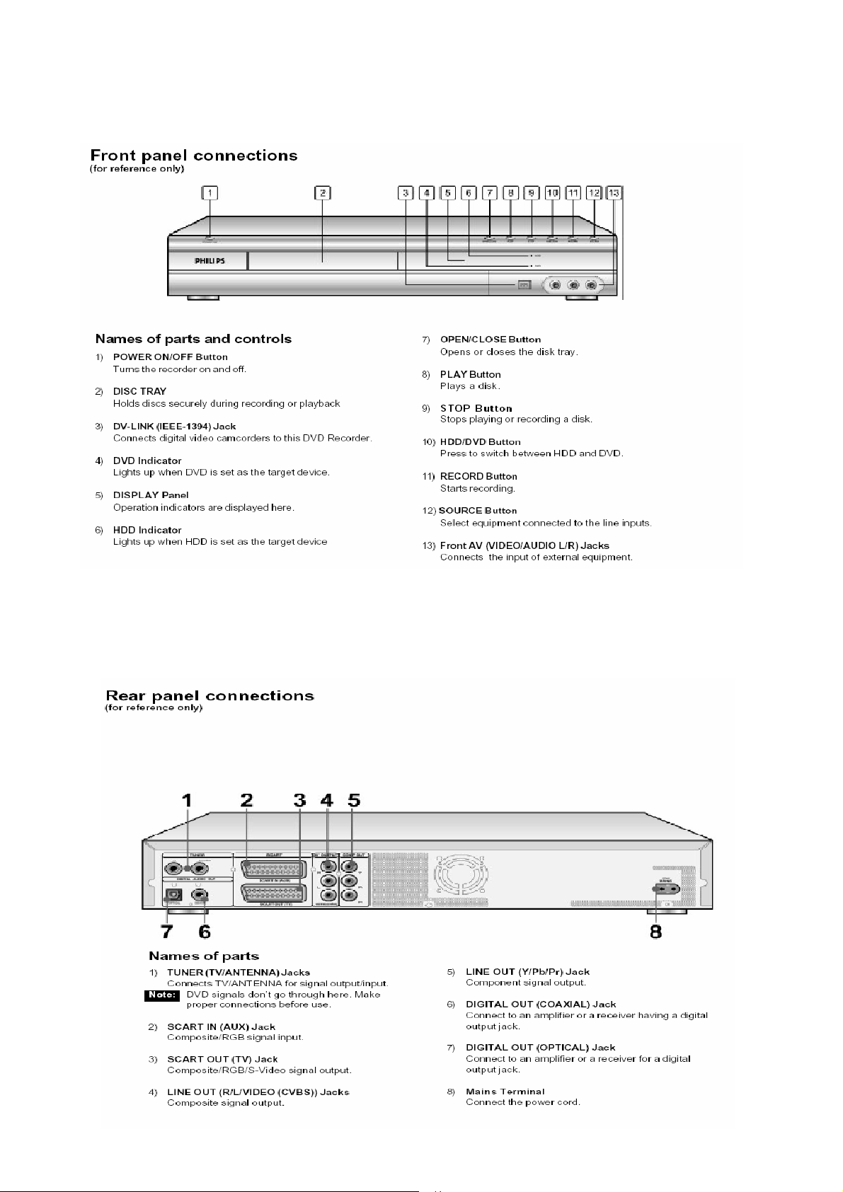
2.2. Front Panel
2-2
2.3. Rear Panel
Page 6
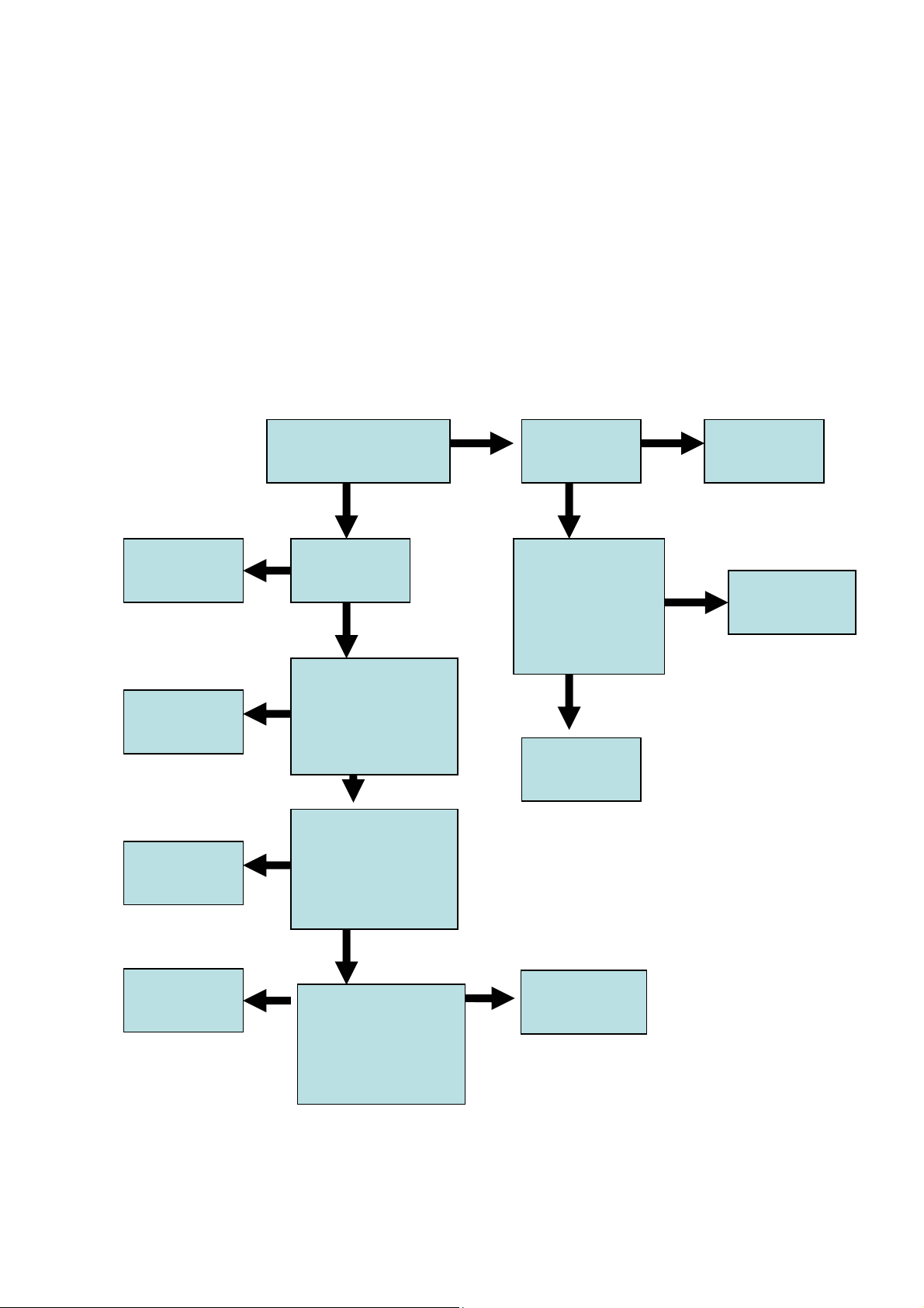
3. Fault Finding Tree
3-1
Start condition:
1. Plug the power cord
2. Power on
Front panel display?
N
Replace front
display board
N
Replace
drive
Display
Normal?
Press “EJECT”buttom
to verify if the player
boot up and also tray
come out ?
N
Power cord
plug?
Y
Open top cover and
use “multimeter” to
verify if the power
Y
module output both
5V&12V
Replace front
Y
Y
N
Plug the power
cord
N Replace power
module
Replace M/B
Replace HDD
N
Put a movie disc
and press the “play”
to verify if AV output
corret?
N
Use the “Erase”
function of the “disc
tool “ to verify if the
HDD work normal?
Y
Y
Y
display board
NPF
Page 7
3-2
Start condition:
1. Plug the power cord
2. Power on
Recording
Select Target to
Select Source view
and display OK
N
Select AV sources
but no
i i
N
AV Sources video is
black&white or
if
N
Select DV but no
video
Y
HDD/DVD OK
Y
Check
connection
Check if TV system
Y
of input device is
different
Gray screen-check
Y
Connection
Press Record
button to start
N
Show “Protected
Content”
N
Show “Wrong
Signal Type”
N
Show “Write Fail”
di
Source DVD is not
Y
allowed to
Y
Recording disc was
formatted when
Y
Bad write quality
on this disc
iff
Page 8
3-3
Start condition:
1. Plug the power cord
2. Power on
DVD Playback
Select Target DVD,
eject
Y
Load supported
disc DVD+-R/RW,
CD-R
N
Invalid disc or
Data disc
Y
Y
Auto-play DVD
VCD SVCD and
Media Disc
Not supported
format
N
Blank disc
Y
Show “Preparing”
then start
pre-format for
Page 9
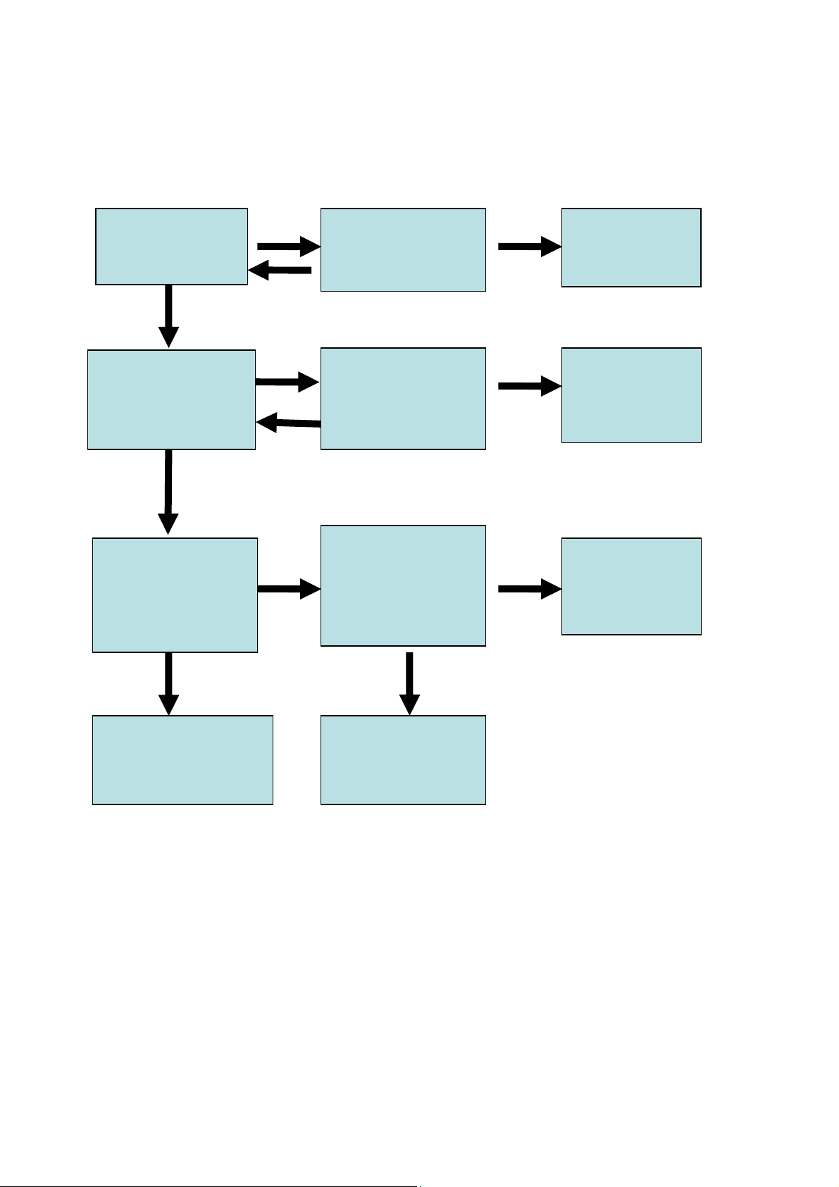
Tuner :
Select the source into TV mode first
3-4
TV signal
on screen ?
Y
Display normally ?
Y
Check if the
Audio output
properly ?
N
Y
N
N
Can scan
All channel?
Can Fine tune
Channel?
Y
Check if Audio
/Video output
properly when
DVD playback ?
N
N
Y
Replace Tuner
Board
Replace Tuner
Board
AV output
issue
Y
No problem found
N
Replace Tuner
Board
Page 10

3-5
Reference of defect symptoms for repair
• After power cord plug in ,LED no display , but AV output normal after power
on -> replace display board
• After power on , the color of the screen isn’t correct -> replace M/B
• After power on , the fan doesn’t work -> replace power module / Fan
• Can’t eject or show “No Disc” -> replace drive
• Can’t auto format any brand new disc -> replace drive
• Recording will auto stop or hang -> replace M/B & drive
• Playback will have mosaic -> replace M/B
• Can’t format HDD -> replace HDD
• Can’t record with HDD -> replace HDD
• No Audio or audio output abnormal -> replace M/B
• Optical / Coaxial no output when the setting is set as DTS output -> replace
M/B
• Can’t update F/W through drive -> replace drive
• Can’t detect DV when plug in/out with a DV -> replace display board
• AV1 input mode doesn’t output video / audio when connected to a normal
external AV source -> replace display board
• AV2 ( Scart) / S-Video input mode doesn’t output video / audio when
connected to a normal external AV source -> replace M/B
Page 11
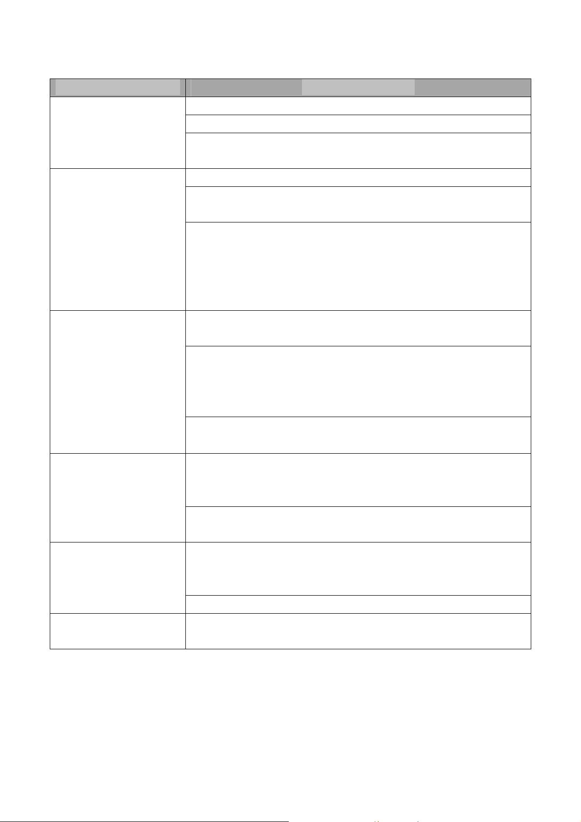
3-6
Module Fail / Problem Remedy / Symptom
Run Disc Tool/Format/HDD show "Fail", this could be a bad HDD
HDD
DVD Drive
DVD/CD disc
Run Disc Tool/Defragment show "Fail", this could be a bad HDD
Format no problem but show "Write Fail" during recording , this could be a
bad HDD
Load any disc always show "No disc", this could be a bad DVD drive
Load some kind of discs always show "No disc". For example load DVD no
problem, but load CD-R show "No disc", this could be a bad DVD drive
Cannot open tray. User can try to power off the recorder, and then press
"Eject" to boot again. If still can not open, this could be a bad DVD drive.
If tray open successfully and there is a disc inside, it's the disc cause drive
busy. Try another disc, if user can tray in/out no problem, the drive should
be ok.
Run Disc Tool/Format/DVD show "Fail". This could be a bad disc or not
compatible with our DVD drive.
Format no problem but show "Write Fail" then stop during recording. Press
"Record" again may be user can continue record, but part of the
audio/video on this disc may not smooth. This could be a bad disc or not
compatible with our DVD drive.
Take long time to load disc then show “Invalid Disc". The disc could be a
bad disc or unsupported format
Connect power cord, but LED display show nothing, Press remote or
button on the panel still nothing happened. This could be a power board
Power
Remote
Front Panel
problem
Replace power cord if find any available. We use a common power cord
user may able to find the same one on his other electronic products
Press buttons on remote but nothing happened, system can still power on
by buttons on panel. OSD doesn't show system receive any key. This
could be a bad remote or ran out of battery.
Or it could be a bad receiver on the front panel
System can power on and work by remote no problem, but press buttons
on panel does not work. This could be a bad front panel
Page 12
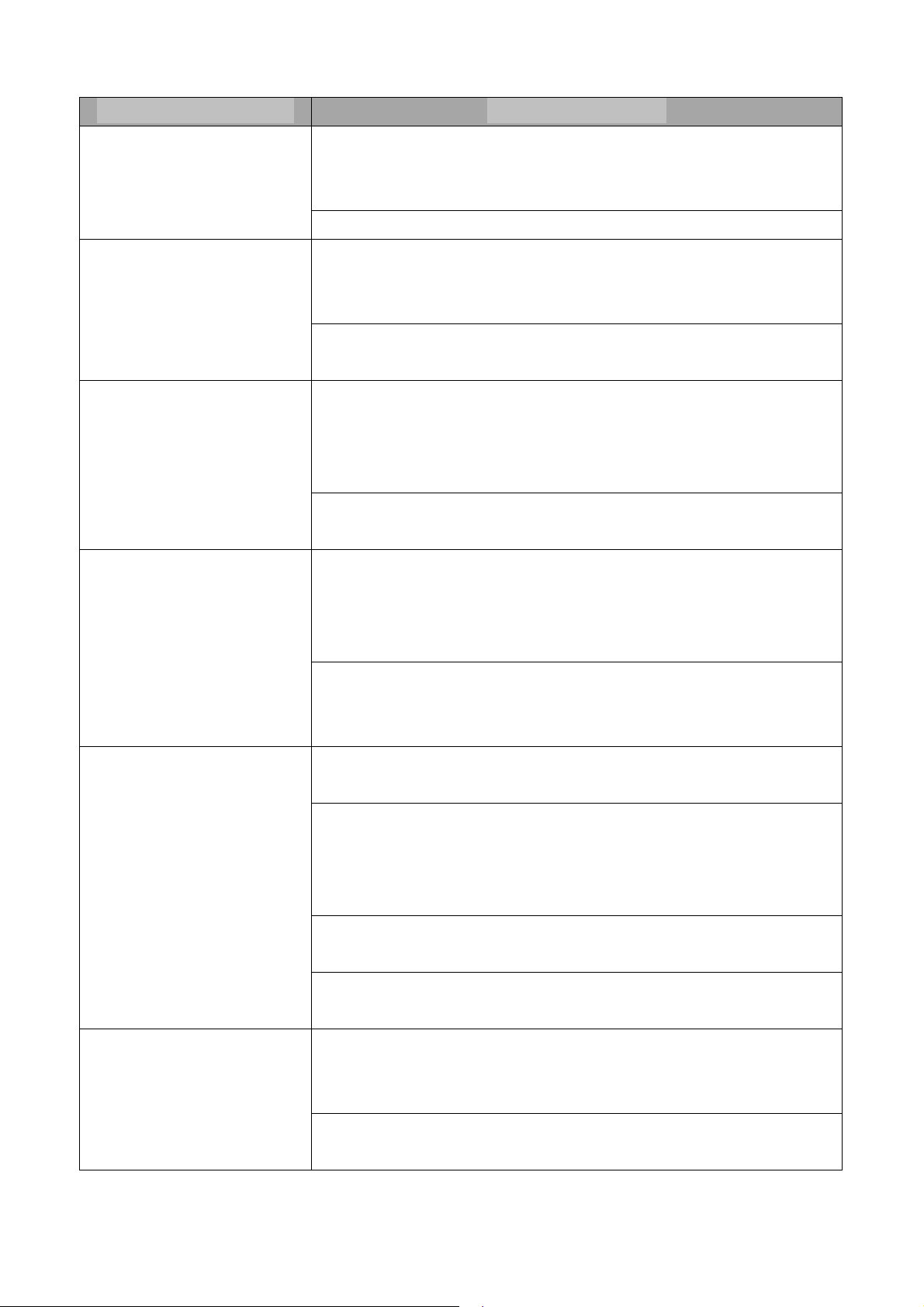
3-7
Module Fail / Problem Remedy / Symptom
Can not see any display or color abnormal, video distortion. Make sure
Video Output
Audio Output
TV Tuner
cables connected correctly. Try another output like S-video, AV,
Component, and Scart.
Run SETUP to select available video output
Can not hear any sound output through speakers of TV or amplifier.
Make sure cables connected correctly. Try another output like AV,
optical, coaxial
Playing DVD movie, when select DTS out on DVD audio menu no audio
output. User needs to run SETUP/Audio/DTS to set DTS ON
Run SETUP, Tuner setting correctly, but after scan TV channel can not
select correct TV programs. Run SETUP/ Tuner/TV signal, select Antenna
or Cable then run "Channel Scan" again, don't use "Auto". "Auto" will
re-arrange channel table and remove channel numbers not available.
User selects TV signal/country correctly, after scan still cannot select
channel, this could be a bad TV tuner.
Connect external source like AV, S-video, Scart, DV-link (1394) can not
see the video input. Make sure cables connected correctly. If these
External source
Can not Real-time Record
signals connect to other AV products no problem. This could be a bad
connector
For DV, user need to know the DV is NTSC/PAL, and the playing DV
tape is NTSC/PAL. They must be the same TV type as the recorder to
make it works properly.
Show "Protected Content", it's Copy-Protected and not allowed to
copy
Show "Wrong Signal Type" when record to disc. The disc was formatted
by different TV system (NTSC/PAL). For DVD±RW, user can reformat this
disc (contents on this disc will be erased). For DVD±R, user can only
change another disc
Press "Record" shows key blocked, will not start recording. Maybe user
select wrong Target device. Press Target to choose HDD/DVD
Empty DVD-R/RW, CD-R/RW user needs to format by Disc Tool before
recording
Open "Timer" record again, there is a message shows why it failed,
Can not Timer Record
please move the cursor to column status and it will show the reason it
fails
Selected recording "Target" is unable to record when Timer starting
time
Page 13
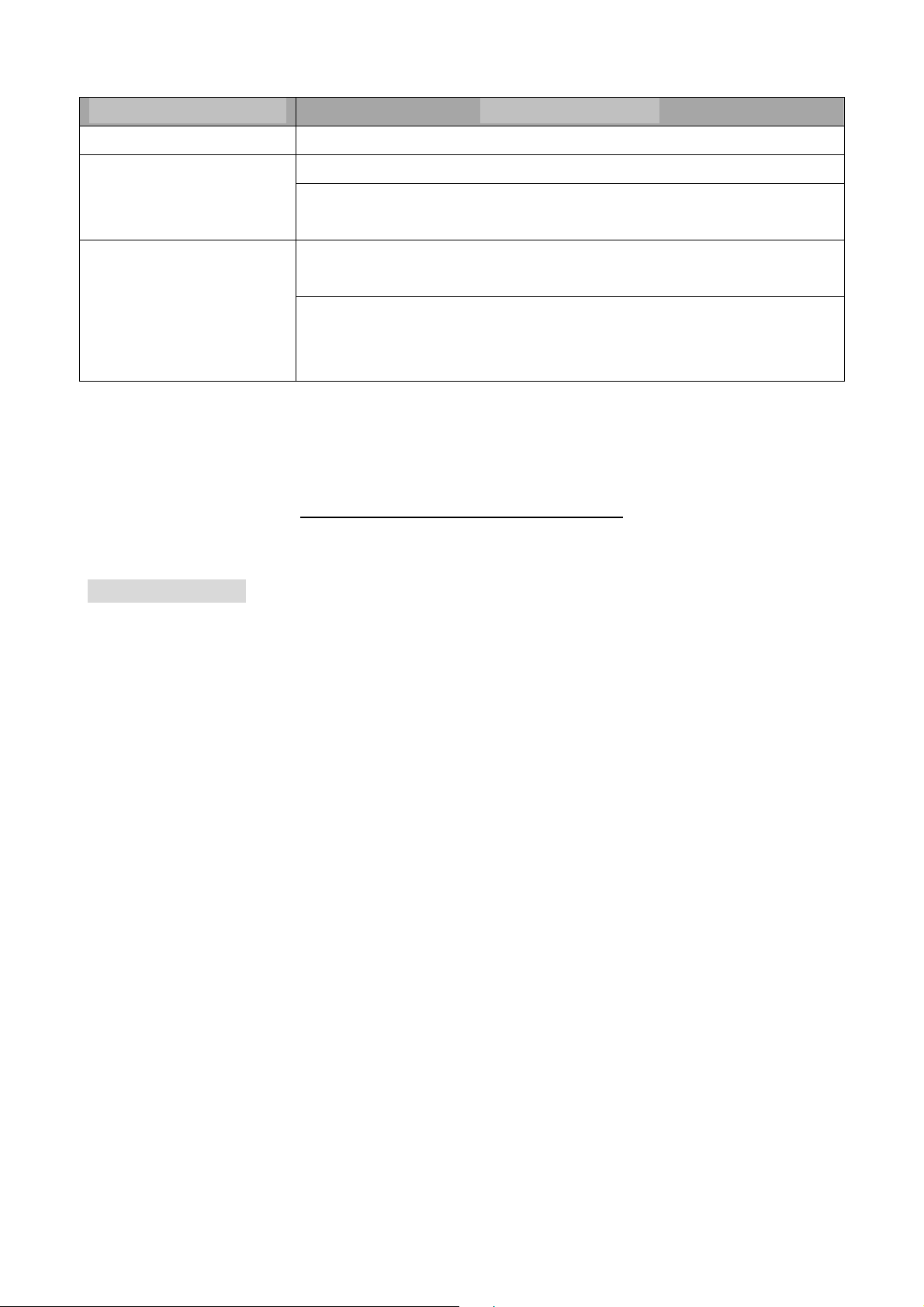
3-8
Module Fail / Problem Remedy / Symptom
Cannot play a disc
Copying
System Upgrade
If it's not "Invalid disc", could be unsupported format/contents in the disc
Show "Fail" when copying files/discs, it could be unsupported format
Show "Fail" when copying recorded DVD+VR title, it could be out of disc
space
Follow the firmware update procedure in the chapter”Firmware update”.
If upgrade failed (power failure during upgrade or …), maybe every time
system power on will show "Put Cd In". Users most load the upgrade disc
again to recover.
Trouble Shooting Guide (DVDR520H)
1 Just “HELLO”
1.1 First recognize what kind of “Hello” it is. You have got two types; one with Power
on and one after Power on, when the DVD starts up.
1.2 If the unit takes a long time to complete the power-on process, check IDE
cable (or 4 IDE connector: connecting between Loader & HDD) whether
assembly / connecting properly or not.
1.3 To check the connector between main board and power module had been
asembled / connected properly. ( Fan on rear panel should rotate
continuously ) if there
is no power supplying to main board ( Yellow: +12V <-> Red: +5V measured wth
universal voltage meter ), replace / change another new Power Module.
1.4 Check the FFC (18 pin) cable between main board and display board had
been assembled connected well.
1.5 If after checking above still Just “Hello” do the following:
Replace/change another new Main Board; if still not work,
Replace/change another new DVD writer ( Loader ) if still not work,.
Replace/change another new HDD;
Page 14
3-9
2 No Display On LED Module
2.1 Put a paper in between the M/B and the barebone, for preventing the M/B
shortcut with ground and Re-test again.
2.2 To check the connector between main board and power module had been
assembled / connected properly. (Fan on rear panel should rotate
continuously) if there
Is no power supplying to main board ( Yellow: +12V <-> Red: +5V measured
with universal voltage meter ), replace / change another new Power Module.
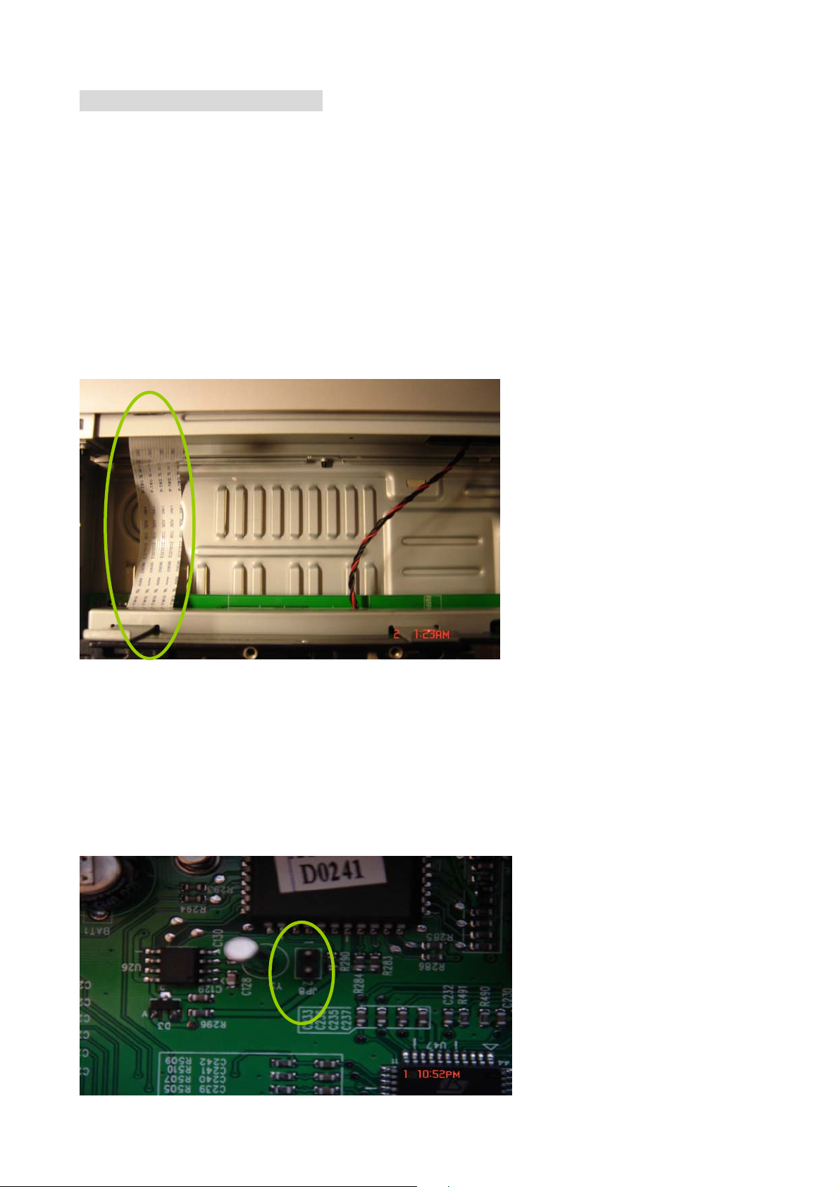
2.3 Check the FFC (18 pin) cable between main board and display board had
been assembled connected well.
2.4 Short the JP8 (on the main board) with jumper,
and then, plug with power cord to check if the text on the LED module had
been lighted on. (Test mode of Display Board had been activated). In case the
answer is negative, replace / change another new Display Board.
2.5 Replace / change another new Main Board. (There should be something wrong
with IC component: AT89S52, DMN-8652 .....)
Page 15

3-10
3 Loader (DVD writer) Failure
3.1 Tray can’t open
3.1.1 Disassemble the Loader, and press the eject button on the Loader (with
power
supply connected : 4 pin connector) to check whether the tray can open
or not. Re-assembly DVD writer (Loader), pay attention to assembly issue
(Plastic layer of Loader stuck to front) and the position of IDE cable (40 pin;
flat cable).
3.1.2 Check the FFC (18 pin) cable between main board and display board
had been assembled / connected well.
3.2 Not ready ( Loader can't identify / recognize the disc )
3.2.1 In this case update the loader firmware to latest version. Please select
several kind of DVD and CD discs including 8x and 4x DVD+R/RW, and
test if loader
can both playback and record on the disc.
1. If yes, then this maybe a media compatibilities issue. The firmware
update can solve it.
2. If can not playback or record at all, change another new loader.
3. If just can’t record on some disc, wait for a new firmware release or
change another new loader.
3.3 Copy/Recording failure or Mosaic appeared
1. Check if the recorded disc is dirty or scratch. If yes, try another disc to check
again.
2. If no, update loader to latest and check it again.
3. If it still can't work, Replace/change another new loader and check it again.
4. If it still can't work, Replace/change another new Main-board and check it
again.
4 Update FirmWare
4.1 Tray can’t open
4.1.1 Re-assembly DVD writer (Loader), pay attention to assembly issue ( Plastic
layer of Loader stuck to front ) and the position of IDE cable ( 40 pin; flat
cable ).
4.1.2 Check the FFC (18 pin) cable between main board and display board
had been assembled / connected well.
4.1.3 Disassemble the Loader, and press the eject key on the Loader (with
power supply connected : 4 pin connector) to check whether the tray
can open or not. If the answer is negative, Replace / change another
Page 16
3-11
new Loader.
4.1.4 After that, tray still can't open. Replace / change another new Main
Board.
4.2 Put in CD
4.2.1 Put the update \disc on the tray and pressing open/close key to make
the tray close, system would update firmware automatically. This may
take a while, wait for the loader to read the firmware update. When
“error” on panel replace Mainboard
4.2.2 In case the tray still eject in a few seconds later, Replace/change
another new Main Board.
4.3 especially case (Firmware updating fail )
4.3.1 Open the tray and put in the firmware disc, tray in and wait the disc
ready after A-up (AP upgrade) ,start to upgrade the loader, if finished it
will show “done” in LCD panel.
4.3.2 In case d-up (loader upgrade) to 99% then show “error “,
1. Please wait tray-out and remove the update disc ( please note don’t
turn off the power immediately , please wait about 70 seconds) .
2. Press the power key to power off , then restart the power on again .The
set will show " put in CD " then put in update disc and update again..
3. If still fail , change the loader.
5 TV (Tuner Function) Failure
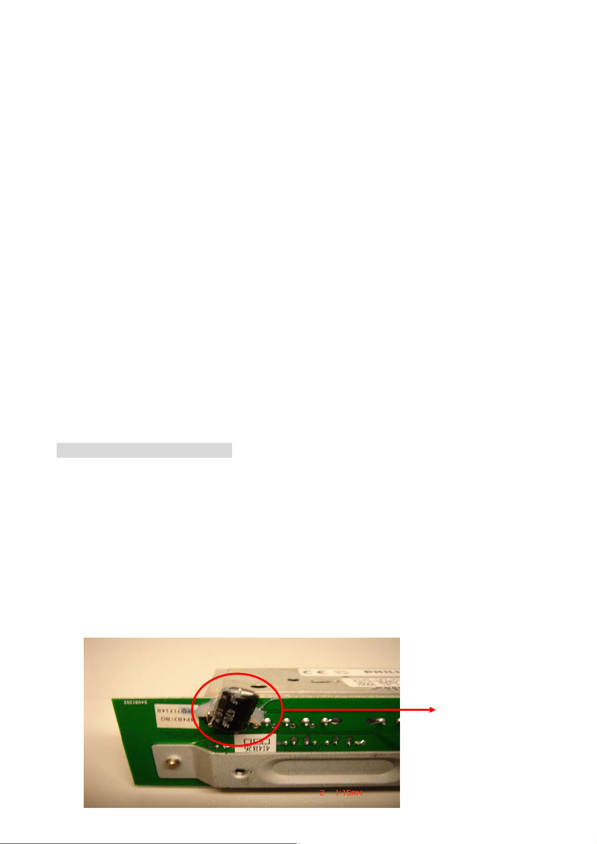
5.1 Make sure that the Tuner Board had been assembled on Main Board at the
right (pin) position and that it is clicked in. Also check the capacitor 470uF on
the Tuner Board must be shorted and is still intact .Look if the pins of the tuner
are still straight and are placed in the right place
5.2 If the answer of former step is positive and all is assembled correctly, Replace
another new Tuner Board.
5.3 In case the tuner (TV) function still had not worked, Replace/change another
new Main Board.
470uF
Page 17
3-12
6 Erasing ( HDD ) Failure
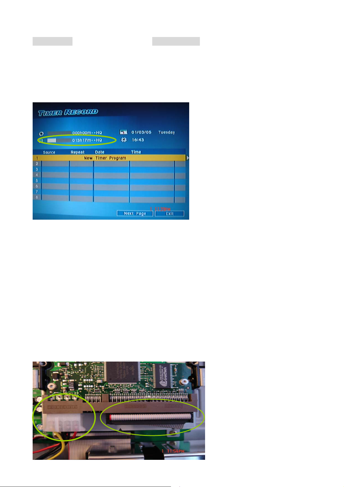
6.1 First confirm that it is a HDD Failure by using the Timer ( If it
recognizes the HDD ) and Erase Function ( Format the
HDD ). See Picture below
6.2 Check if the voltage of connector which connected to HDD is correct or
not.( Yellow: +12V <-> Red: +5V).If no, change the power module. See picture
below.
6.3 If failed, check IDE cable/connector (40 pin) of HDD device whether assembly
/ connecting properly or not.
6.4 If not, connect it well and try again
6.5 If yes, remove the HDD from the set and connect it to a PC to check if the PC
can recognize it or not. (Seagate screen test)!
6.6 If the PC can recognize it ,the format it on the PC and put it back to the set,
then excute erase function again.
6.7 If not, replace / change another new HDD.
6.8 If still Failed try replacing the Main Board.
Page 18
3-13
7 DV Test Failures:
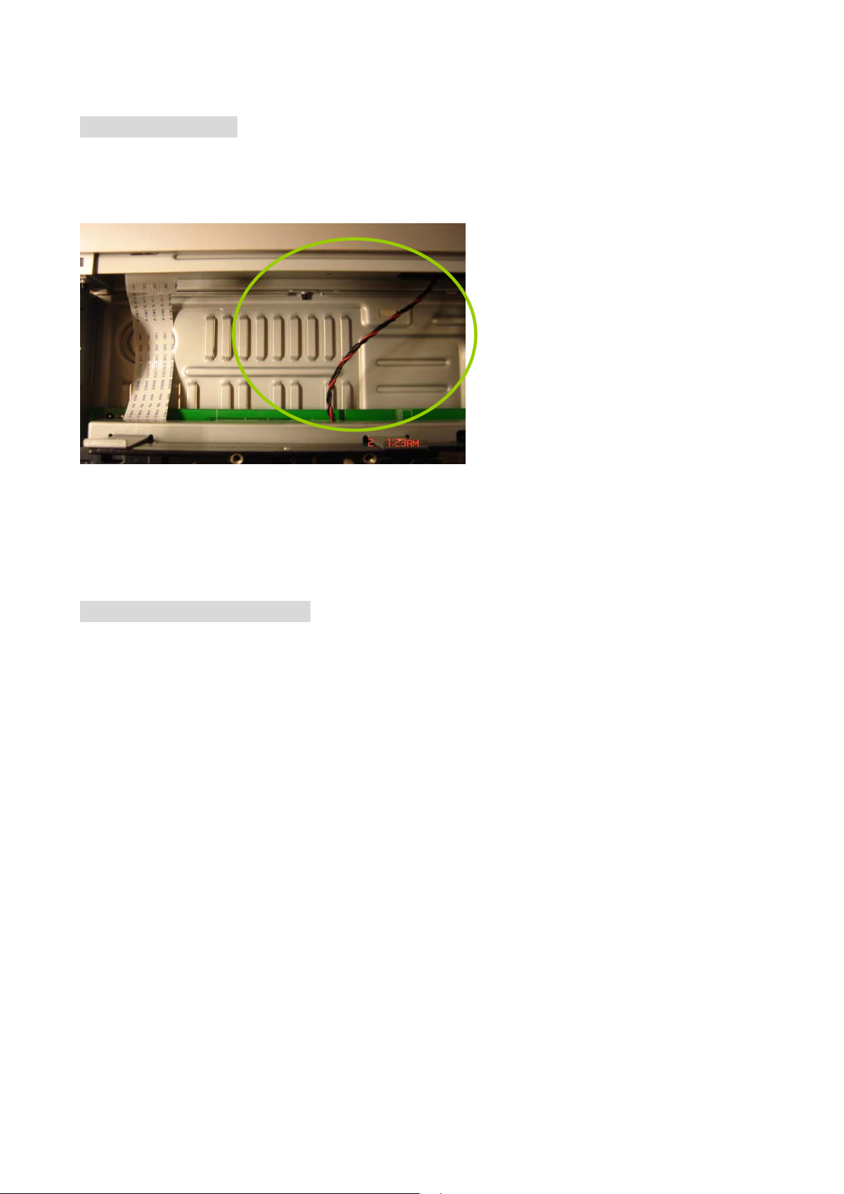
7.1 To check JP1 (5 pin) connector on Main Board had been assembled /
connected properly.
7.2 To check the place/position of Display Board where the 5 pin connector had
been shorted or not, if the answer is yes, Replace/change another Display
Board.
7.3 Otherwise, Replace/change another new Main Board.
8 Output picture abnormal
8.1 Black screen (LED display CH2)
8.1.1 Make sure that the Tuner Board had been assembled on Main Board at the
right (pin) position and to check if the capacitor on the Tuner Board is open
or shorted.
8.1.2 If yes , replace another new Tuner Board.
8.1.3 Otherwise, Replace/change another new Main Board.
8.2 No picture output ( while Playback )
8.2.1 In case no scart out, please make sure the RCA out is ok or not.
1.If yes and picture abnormal, update firmware to latest and check it again
via scart
2.Otherwise , replace another new Main Board.
8.3 No picture output ( while from AV1 input )
8.3.1 To check the connector between main board and display board had been
assembled / connected properly
8.3.2 source from AV1(front) : exchange new front panel to make sure workable
or not
8.3.3 if still failed, replace another new Main Board
Page 19
4-1
4. Disassembly introductions
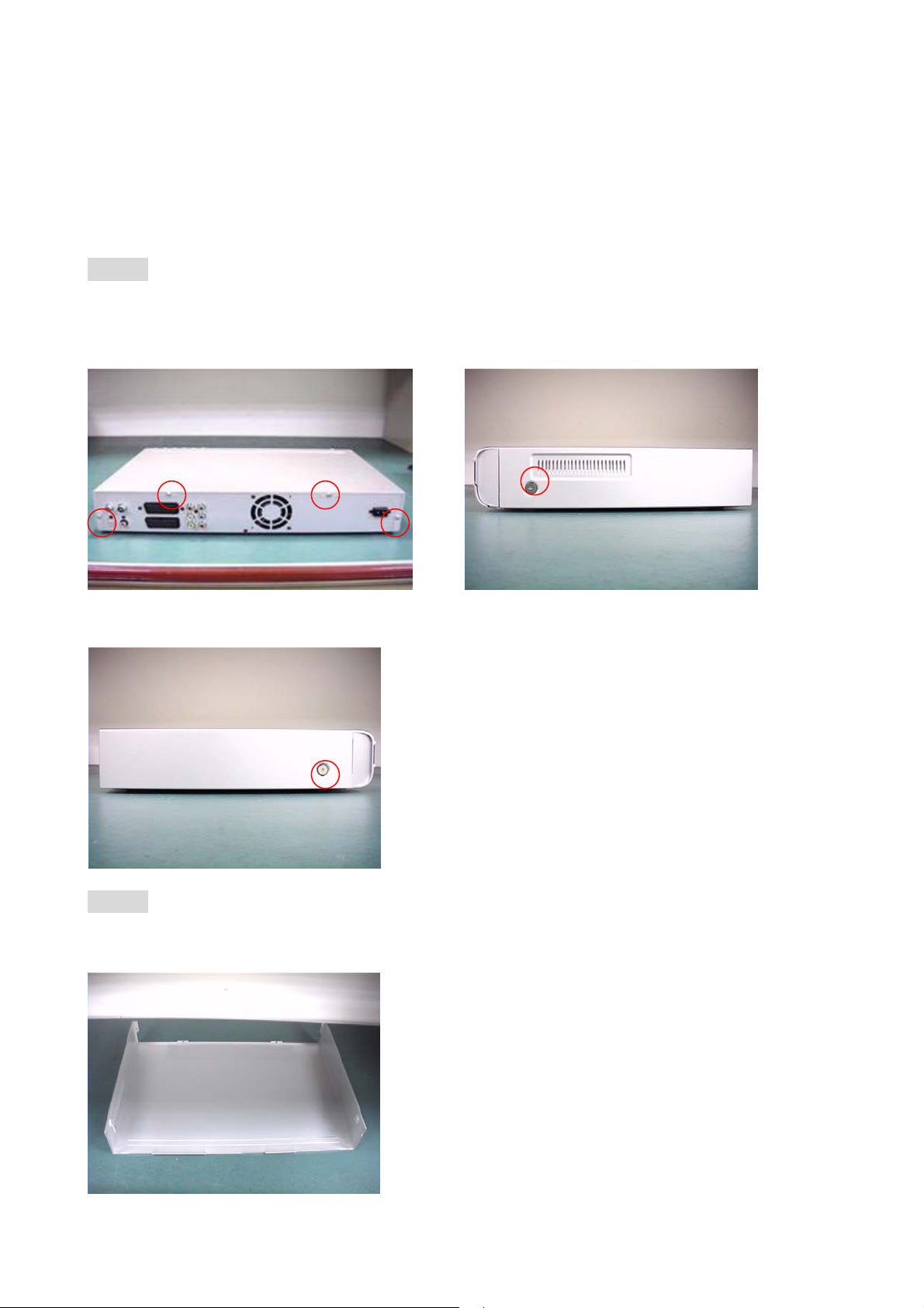
4.1Disassemble the TOP-COVER:
Step 1:
Loosening the fixed screws of the TOP-COVER totally 6 screws, 4 on the rear panel
and 1 on the left side and the other on the right side of the TOP-COVER, (as PICTURE
1 & 2 & 3)
(PICTURE 1) (PICTURE 2)
(PICTURE 3)
Step 2:
Pull back to remove the TOP-COVER and let the cover-top lie on horizontally
smooth desk to prevent being out-of-shape place upside down (as PICTURE 4)
(PICTURE 4)
Page 20
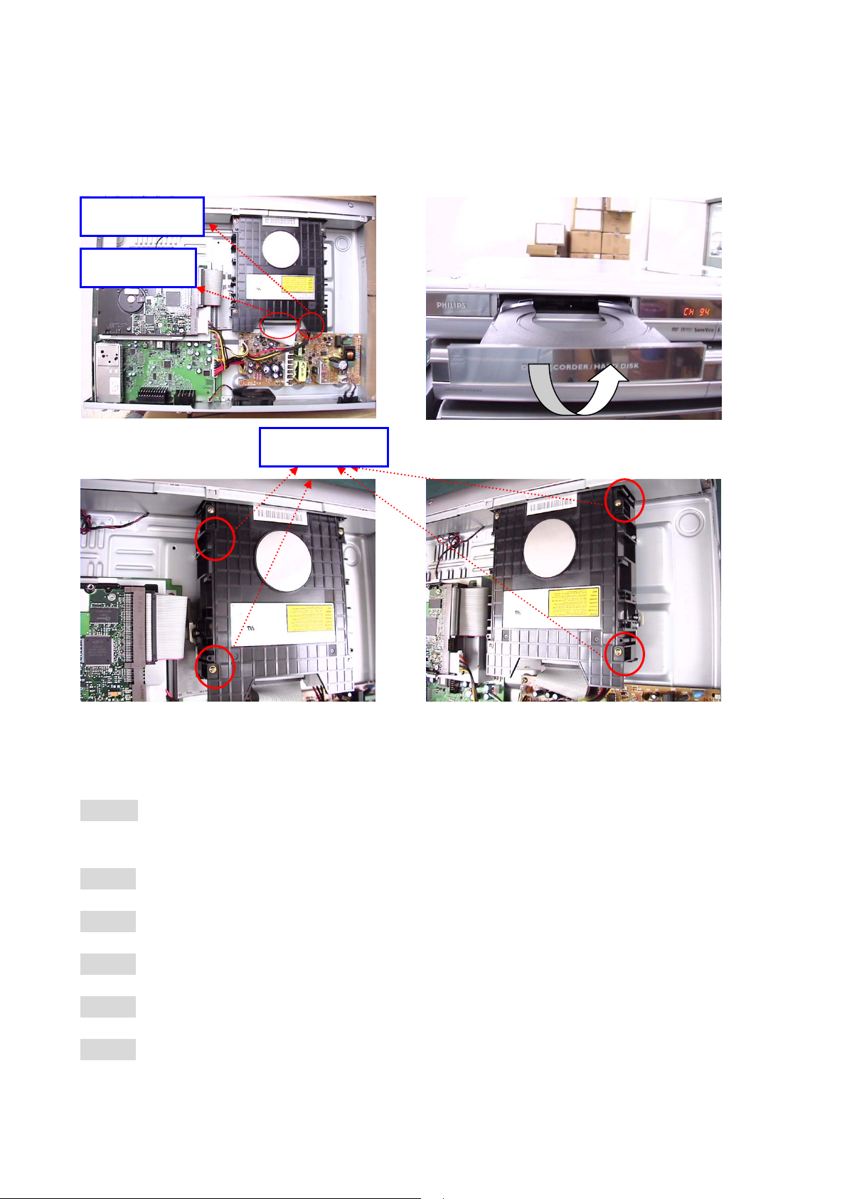
4.2 Disassemble the Drive:
4-2
Power cord
IDE cable
(PICTURE 5) (PICTURE 6)
4
SCREWS SCREWS
1
3
(PICTURE 7 ) (PICTURE 8)
Step 1: Tray out Æ pull out the door and lift up to disassemble the tray door (as
PICTURE 6)
Step 2: Tray in Æ Power off Æ unplug the power cord
Step 3: Disassembly the top cover
Step 4: Unplug the power cord and IDE cable (as PICTURE 5)
Step 5: Remove the four fixed screws of the drive (screw 1~4 as PICTURE 7 &8)
Step 6: Remove the Drive
2
PS: If the tray is jammed can’t be out on step 1, please unplug the power cord
first ,then follow the step 3-5 ,and then lift up the drive on the rear side to separate
Page 21
the tray door and tray.
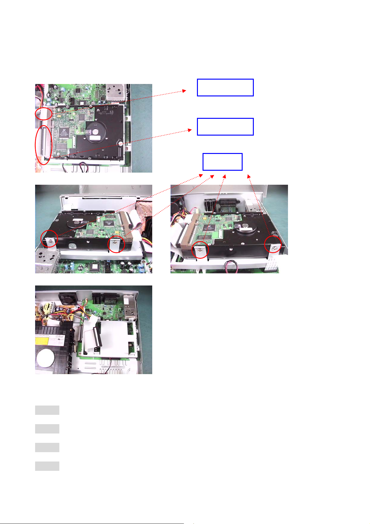
4.3 Disassemble HDD:
(PICTURE 9)
4-3
Power cord
IDE cable
SCREWS
2
1
(PICTURE 10) (PICTURE 11)
(PICTURE 12)
Step 1: Disassembly the top cover
3
4
Step 2: Unplug the power cord and IDE cable (as PICTURE 9)
Step 3: Loosen the screws off the chassis (1~4 in PICTURE 10 & 11)
Step 4: Take out the HDD (as PICTURE 12)
Page 22
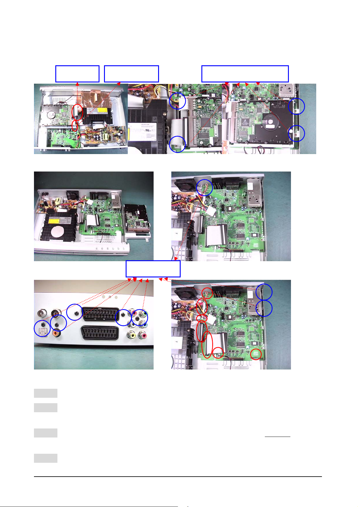
4.4 Disassemble the M/B:
4-4
IDE cable
Power cord
2
SCREWS
4
3
1
(PICTURE 13) (PICTURE 14) (PICTURE 15)
1
(PICTURE 16 ) (PICTURE 17)
SCREWS
1
3
2
4 5
2
1
(PICTURE 18) (PICTURE 19)
Step 1: Unplug the power cord and IDE cable of the HDD module (as PICTURE 13)
Step 2: Remove the HDD module from the M/B first, unfix the 4 screws of the HDD
module (as PICTURE14, 15, 16)
Step 3: Unfixed the screw of the M/B and remove all the cable (7 cables)
connected to M/B (as PICTURE 17 & 19)
Step 4: Loosen the 5 screws off the rear panel (as PICTURE 18)
Note: Tuner can be removed and reused if isn’t broken when M/B is disassembled
Page 23
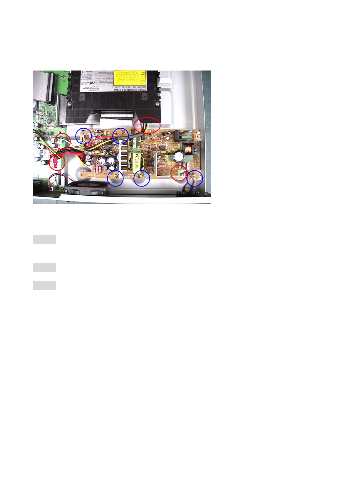
4-5
4.5 Disassemble the Power Module
1
Step 1: Disconnect all the cables connected to other module (total 4 cables as
red circle in PICTURE 20)
Step 2: Loosen the screws off the chassis (1~5 in PICTURE 20)
Step 3: Take out the power module
2
3 4
(PICTURE 20)
5
Page 24
4.6 Disassemble Tuner board
4-6
(picture 21) (picture 22)
SCREW
(picture 24 ) (picture 23)
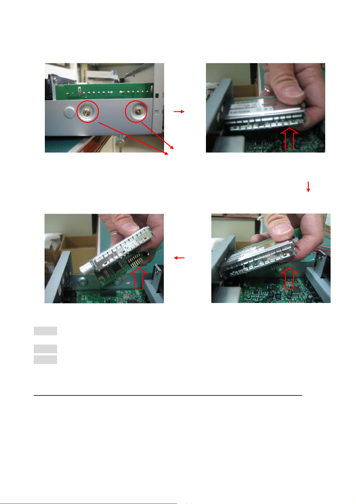
Step 1: Unplug the power cord before replace the Tuner board
Step 2: Loosen the screws off the chassis (2in PICTURE 21)
Step 3: Take out the tuner board follow the disassemble direction as picture 22.23.24.
Note : When assemble Tuner Board please follow the sequence from picture 24 –> 21
Page 25
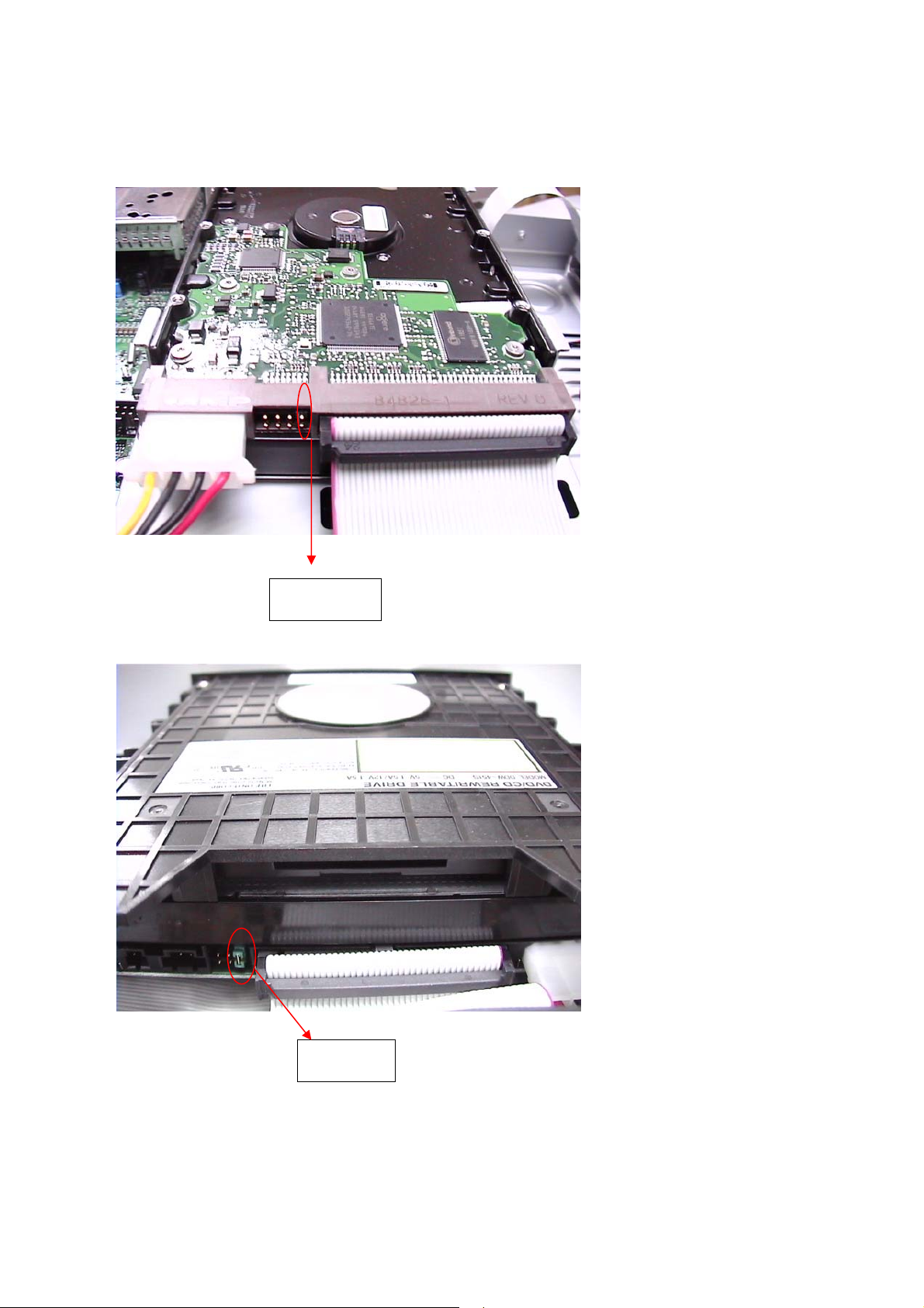
4.7 JUMPER Settings
HDD
4-7
ODD
JUMPER
JUMPER
Page 26
5. Firmware Update
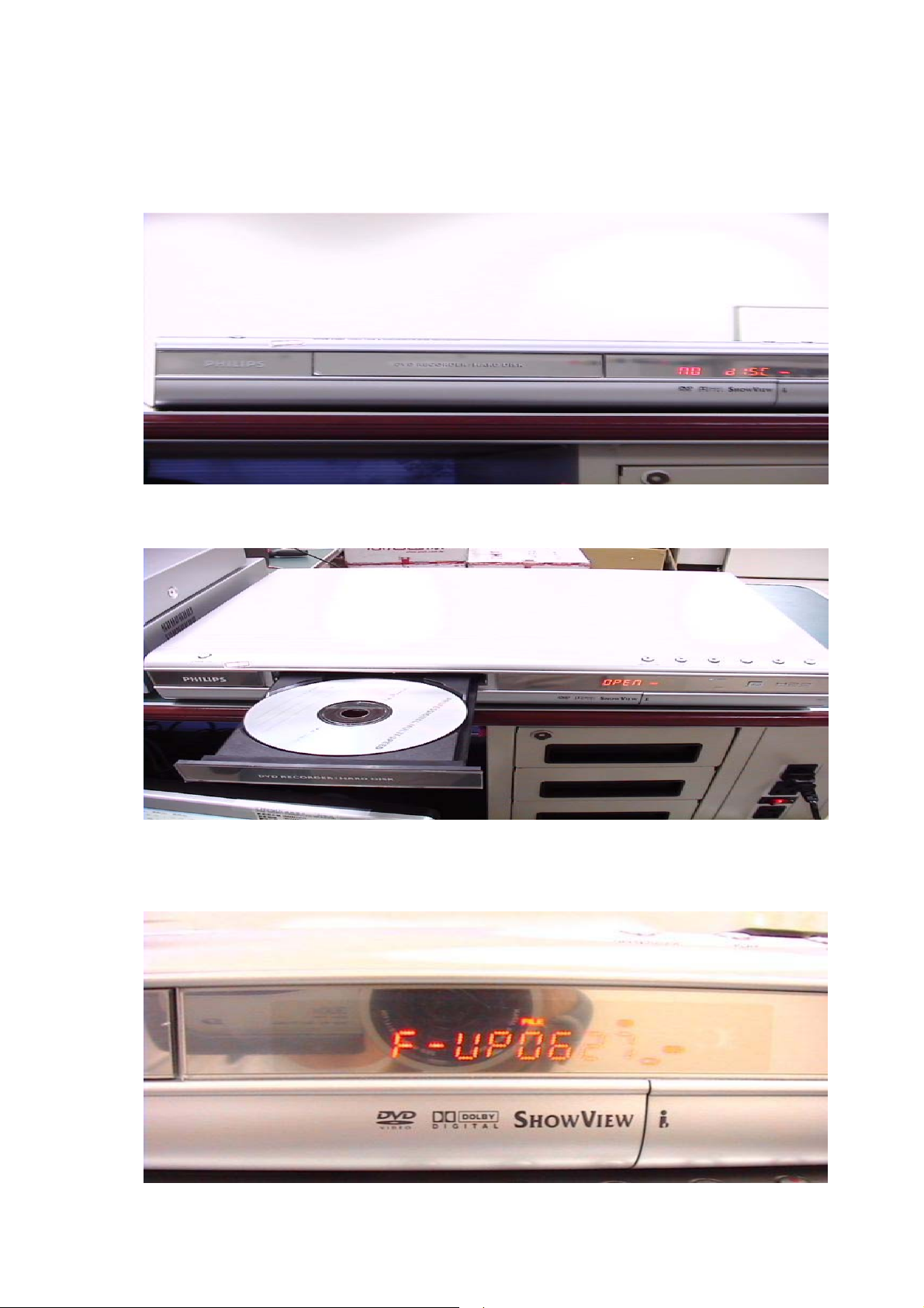
1. Burn the firmware on a single-session ISO disc.
2. Power on the system.
5-1
3. After system is ready, load the firmware update disc.
4. System will start detect the firmware image and if the image is detected,
LED will show "F-UP xxxx", where "xxxx" is the build number.
Page 27
5-2
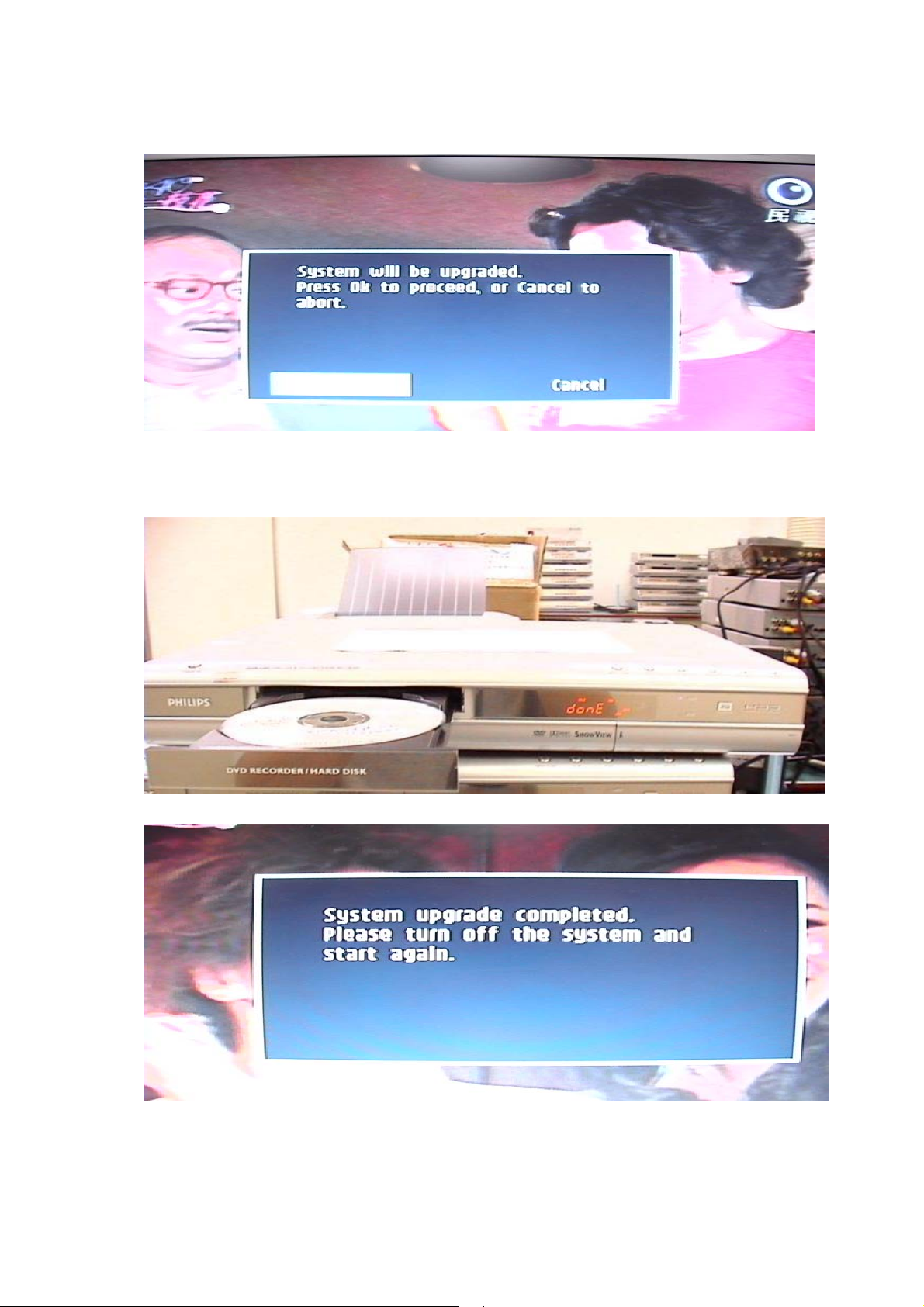
5. If system detects the image file, a confirm dialog will display on the screen.
Follow the instruction to complete the update process.
6. If system firmware is updated without error, LED will show "done". Else
"error" will show.
7. Reboot the system.
Page 28
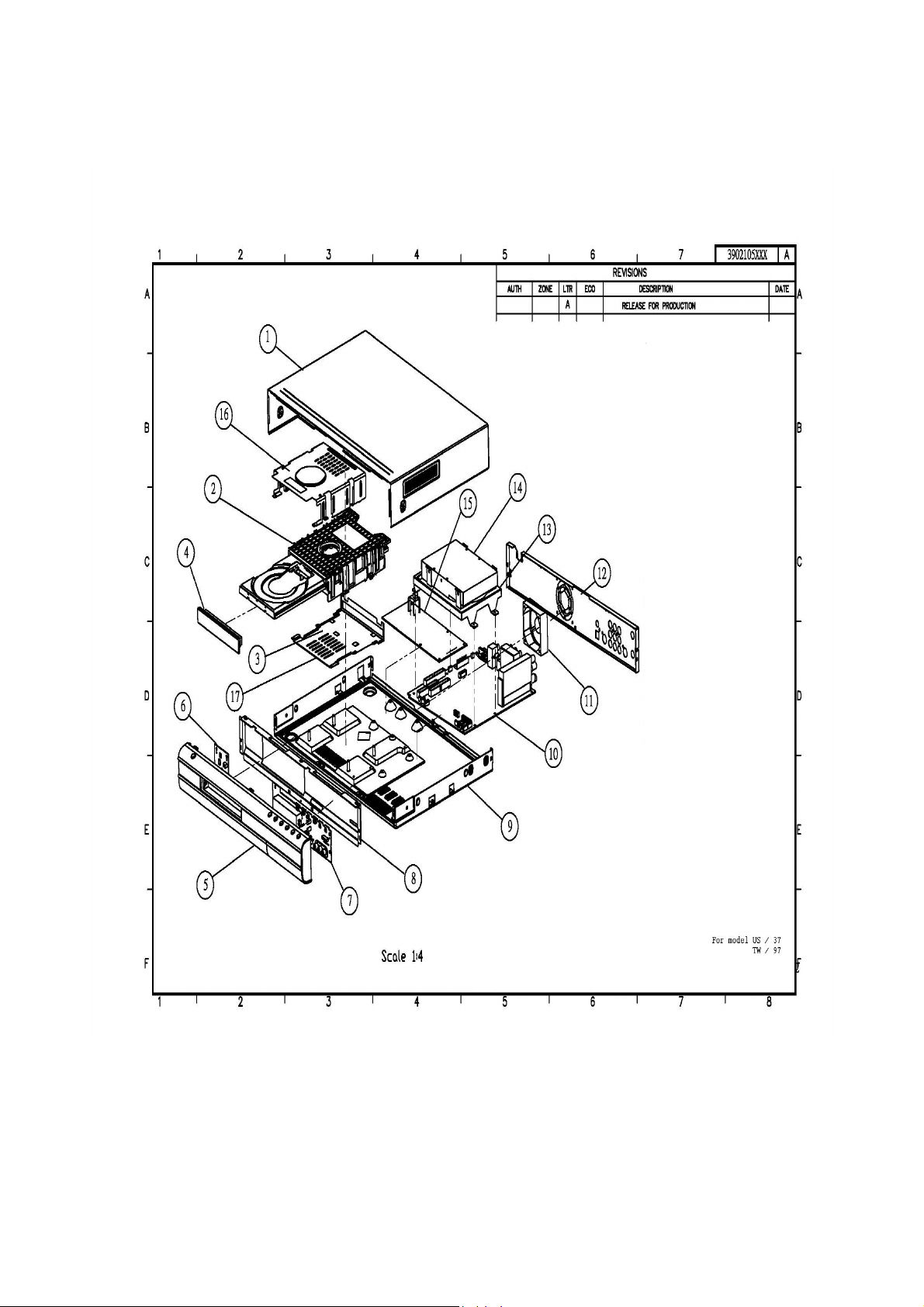
6-1
6. Exploded View & Spare List
Page 29
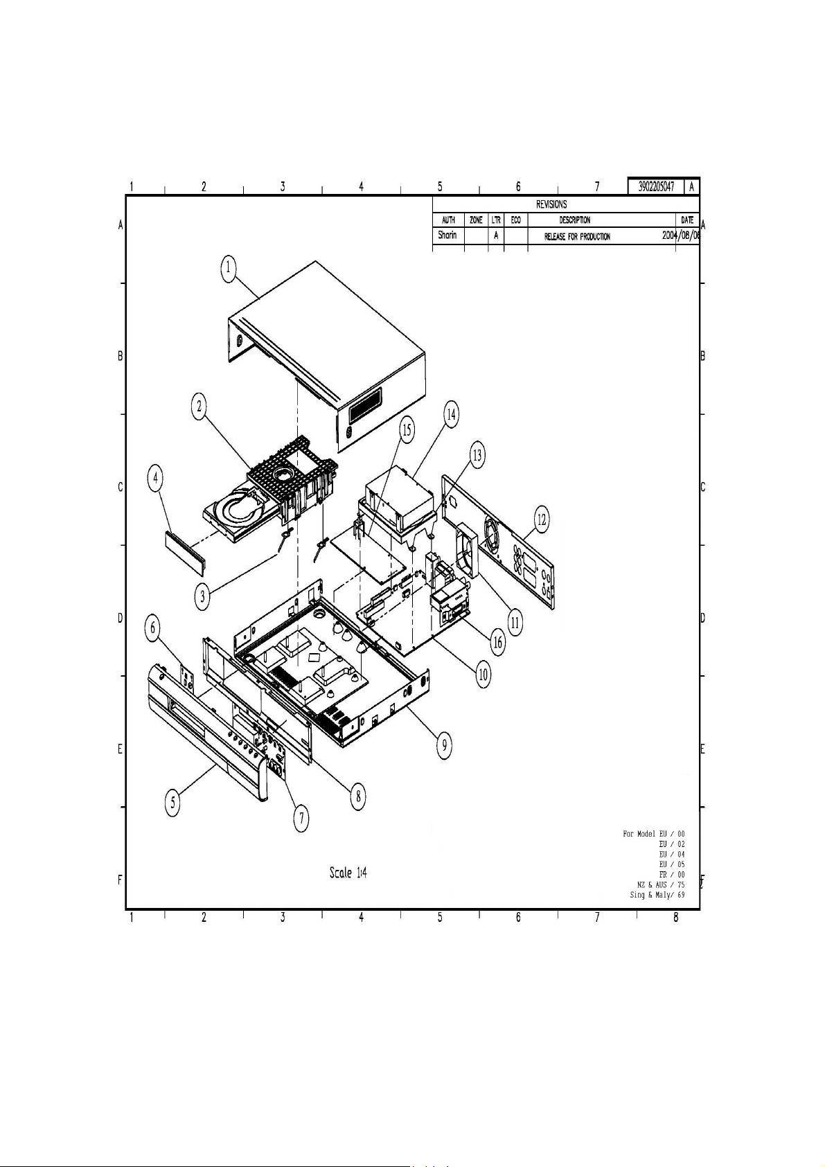
6-2
Page 30

DVD Test Discs
7104 099 91851 LVP12.01
7104 099 96851 CD-RW LOW REFLECTION AUDIO DISC
7104 099 94261 RICOH +R (4 SPEED) BLANK DISC
SERVICE SPARE PARTS
2 9965 000 27118 DVDR MECHANISM MODULE
2 9965 000 32519 DVDR MECHANISM MODULE
5+6+7 9965 000 27119 FRONT PANEL + PCBA ASSY
5+6+7 9965 000 29124 FRONT PANEL + PCBA ASSY
6-3
except /93
/93
/00/02/04
/05
5+6+7 9965 000 29131 FRONT PANEL + PCBA ASSY
5+6+7 9965 000 29051 FRONT PANEL + PCBA ASSY
5+6+7 9965 000 29055 FRONT PANEL + PCBA ASSY
5+6+7 9965 000 32520 FRONT PANEL + PCBA ASSY
10 9965 000 27108 MAIN BOARD W/O TUNER
10 9965 000 29047 MAIN BOARD W/O TUNER
10 9965 000 29052 MAIN BOARD W/O TUNER
10 9965 000 29053 MAIN BOARD W/O TUNER
10 9965 000 29126 MAIN BOARD W/TUNER
10 9965 000 29056 MAIN BOARD W/TUNER
10 9965 000 32521 MAIN BOARD W/TUNER
11 9965 000 27109 FAN
14 9965 000 26095 HD DRIVE HDD_80G_5400
15 9965 000 29048 POWER BOARD
/00/02/04/05/69/75
15 9965 000 29130 POWER BOARD
15 9965 000 29057 POWER BOARD
15 9965 000 32522 POWER BOARD
16 9965 000 27117 TUNER UNIT PAL
& Germany
16 9965 000 29317 TUNER UNIT PAL
/00/02/04/05 except France
/00 France & Germany
16 9965 000 29050 TUNER UNIT PAL
/37
/69/75
/97
/93
/00/02/05
/04
/69
/75
/37
/97
/93
/37
/97
/93
/69/75
16 9965 000 32518 TUNER UNIT PAL
RC 9965 000 27120 REMOTE CONTROL UNIT
RC 9965 000 29125 REMOTE CONTROL UNIT
RC 9965 000 29132 REMOTE CONTROL UNIT
RC 9965 000 29049 REMOTE CONTROL UNIT
RC 9965 000 29054 REMOTE CONTROL UNIT
9965 000 29318 RCA CABLE
/93
/00/02/04
/05
/37
/69/75
/93/97
/69/97
Note: Only the parts mentioned in this list are normal service spare
parts.
Page 31

REVISION LIST
Version 1.0
* Original Release
Version 1.1
* Correction of page 21 - Missing diassembly instruction 7.1
Version 1.2
* Addition of new stroke versions /04, /69, /75 and /97
* Removal of unnecessary pages like Introduction, Supplier Test tools
* Shifting of exploded view to the end of Manual
* Correction & updating of Service parts list
Version 1.3
* Addition of new stroke version /93
7-1
 Loading...