

Page 1
Hookup Pages
Important!
Return your Warranty Registration
Card within 10 days. See why inside.
DVD/CD
5-Disc Changer
DVD781CH
Page 2

8 Hookups
Connecting the DVD Player to a TV only (no stereo or amplifier)
TV has AUDIO (red and white) and VIDEO (yellow) IN jacks
DIGITAL AUDIO OUT
PCM / BITSTREAM
AUDIO OUTVIDEO OUTS-VIDEO OUT
COAXIALOPTICAL
COMPONENT
VIDEO OUT
R L
1
2
Y
Cb
Cr
VIDEO
L/MONO
AUDIO
R
in
1
VIDEO IN
LEFT AUDIO IN
RIGHT AUDIO IN
You may connect the DVD Player several different ways, depending on your existing equipment and your preferences for sound and picture quality. To determine which hookup is best for you, examine the options on the
following pages, then see which best matches your situation. Before you hook up the DVD Player, remember:
● Connect the DVD Player directly to a TV. If you connect the DVD Player to a VCR, then connect the VCR
to the TV, the picture may be distorted by the copyright protection system.
● Turn off the power of all equipment before making any connections.
● Refer to the owner’s manuals of your other equipment for additional information.
● Depending on your connection, you may need to purchase additional cables.
● If you do not connect the DVD Player to a Dolby Digital or DTS Decoder, set DOLBY DIGITAL and DTS
to OFF on the DVD Player. Details are on pages 11 and 38-39. If you play a DVD when the settings are
wrong, the sound will be distorted or you may damage the speakers.
1
Connect the red and white audio cables to the red and white AUDIO OUT jacks on the DVD
Player (either 1 or 2) and to the red and white AUDIO IN jacks on the TV, matching the cable
colors to the jack colors. If the TV has a single AUDIO IN jack, use the white audio cable to connect the
DVD Player’s white AUDIO OUT jack to the TV’s AUDIO IN jack. You will not use the red audio cable.
2
Connect the yellow video cable to the VIDEO OUT jack on the DVD Player and to the VIDEO
IN jack on the TV.
3
Connect the TV’s power cord to a power outlet.
Turn on the TV and set it to the Audio/Video In channel, which also may be referred to as A/V In or
Auxiliary In. This channel usually is located near channel 00. See your TV owner’s manual for details.
4
Connect the DVD Player’s power cord to a power outlet.
Press the POWER button to turn on the DVD Player. “HELLO” will appear briefly on the DVD
Player’s display panel. You should see the DVD logo on the TV screen briefly. If you do not, check your connections and make sure the TV is set to the correct Audio/Video In channel. If there is no disc in the DVD
player, “no DISC” will appear on the display panel.
1
2
Back of TV
(example only)
DVD Player
Page 3
Hookups (cont’d) 9
Connecting the DVD Player to a TV only (no stereo or amplifier)
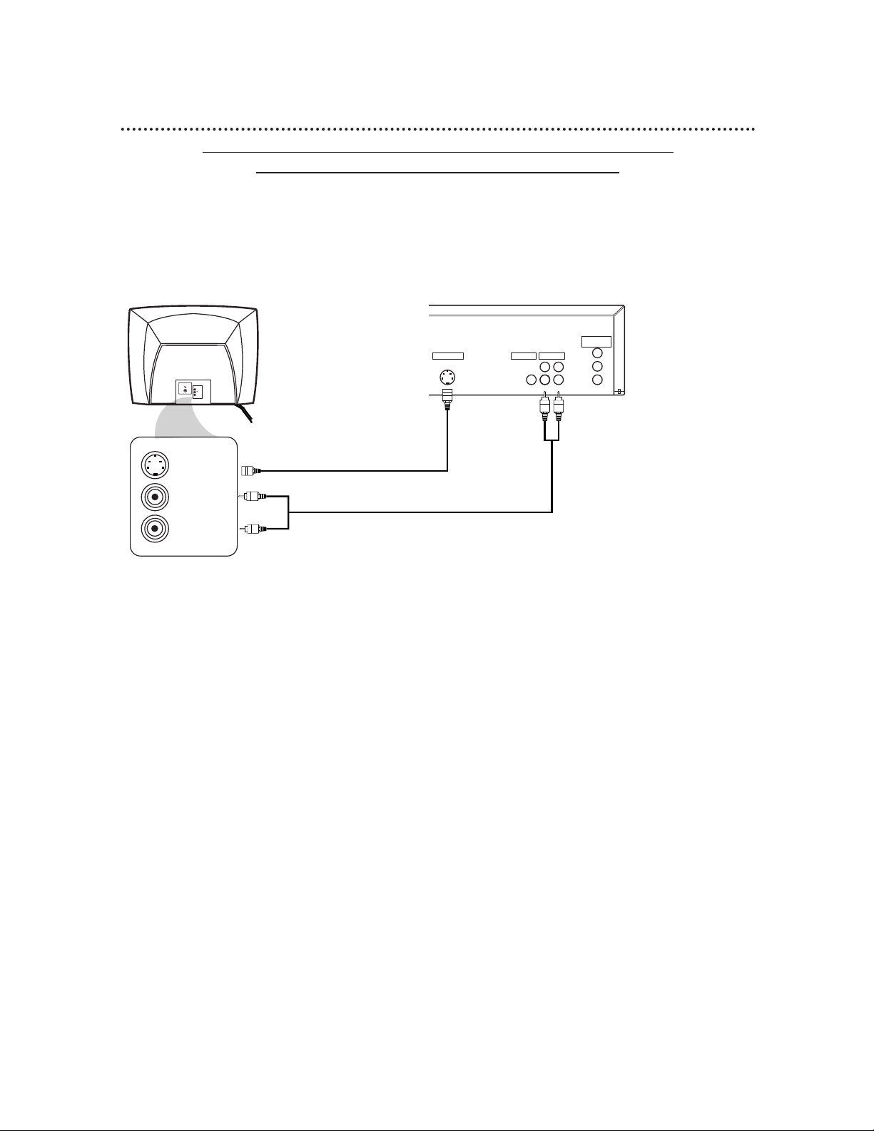
TV has audio (red and white) and S-Video In jacks
● For better picture quality, use an optional S-Video cable to connect the S-VIDEO OUT jack on the DVD
Player to the S-VIDEO IN jack on your TV. You will not use the yellow VIDEO OUT jack on the DVD
Player, and you will not need the yellow video cable.
● Set DOLBY DIGITAL and DTS to OFF on the DVD Player. Details are on pages 38-39. If you play a DVD
when the settings are wrong, the sound will be distorted or you may damage the speakers.
DIGITAL AUDIO OUT
PCM / BITSTREAM
AUDIO OUTVIDEO OUTS-VIDEO OUT
COAXIALOPTICAL
COMPONENT
VIDEO OUT
R L
1
2
Y
Cb
Cr
VIDEO
L/MONO
AUDIO
R
in
1
S-VIDEO IN
LEFT AUDIO IN
RIGHT AUDIO IN
1
Connect the red and white audio cables to the red and white AUDIO OUT jacks (either 1 or 2)
on the DVD Player and to the red and white AUDIO IN jacks on the TV, matching the cable colors to the jack colors. If the TV has a single AUDIO IN jack, use the white audio cable to connect the DVD
Player’s white AUDIO OUT jack to the TV’s AUDIO IN jack. You will not use the red audio cable.
2
Connect an S-Video cable (not supplied) to the S-VIDEO OUT jack on the DVD Player and to
the S-VIDEO IN jack on the TV.
3
Connect the TV’s power cord to a power outlet.
Turn on the TV and set it to the S-VIDEO IN channel. This channel usually is located near channel 00.
See your TV owner’s manual for details.
4
Connect the DVD Player’s power cord to a power outlet.
Press the POWER button to turn on the DVD Player. “HELLO” will appear briefly on the DVD
Player’s display panel. You should see the DVD logo on the TV screen briefly. If you do not, check your connections and make sure the TV is on the correct S-Video In channel. If there is no disc in the DVD player, “no
DISC” will appear on the display panel.
1
2
Back of TV
(example only)
DVD Player
Page 4
10 Hookups (cont’d)
Connecting to a TV and a Stereo
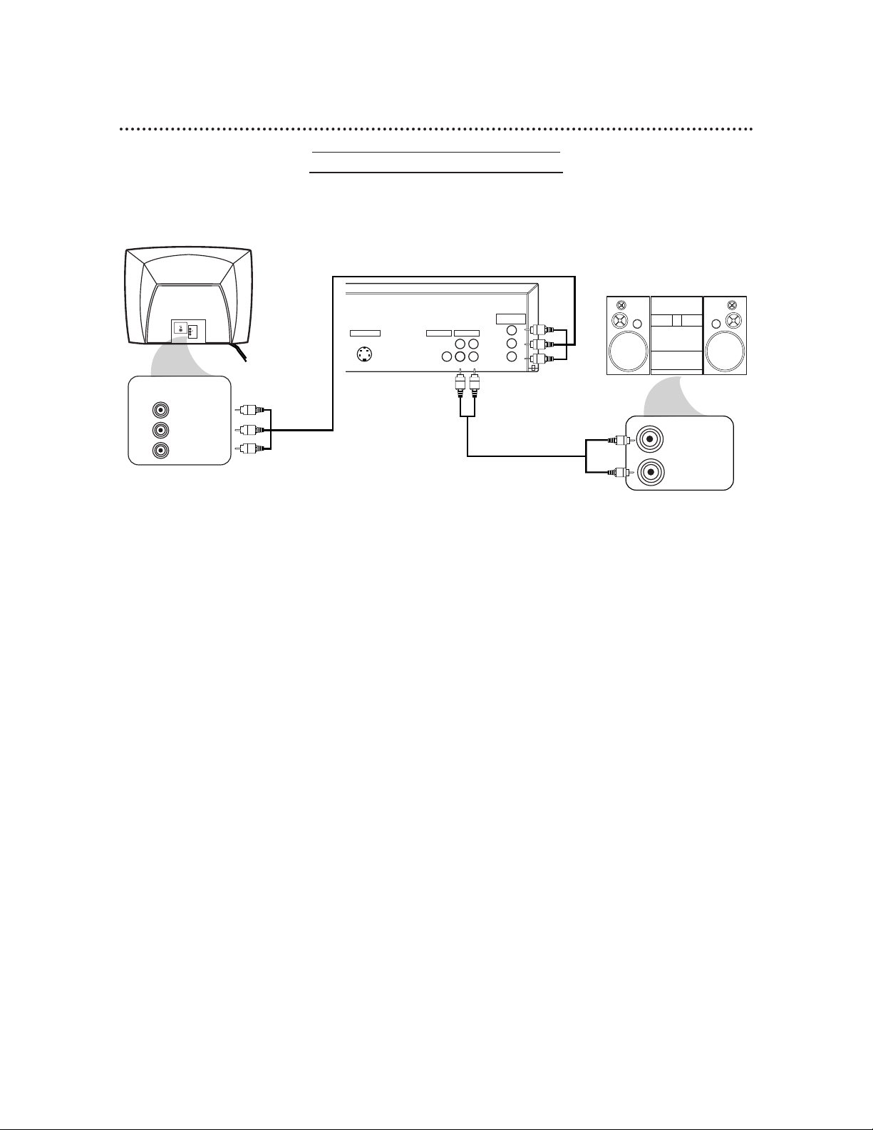
TV has Component Video In Jacks
● Set DOLBY DIGITAL and DTS to OFF on the DVD Player. Details are on pages 38-39. If you play a DVD
when the settings are wrong, the sound will be distorted or you may damage the speakers.
DIGITAL AUDIO OUT
PCM / BITSTREAM
AUDIO OUTVIDEO OUTS-VIDEO OUT
COAXIALOPTICAL
COMPONENT
VIDEO OUT
R L
1
2
Y
Cb
Cr
Y
Cb/B-Y
Cr/R-Y
AUDIO (RIGHT) IN
AUDIO (LEFT) IN
Back of TV
(example only)
COMPONENT
VIDEO IN
Back of Stereo
(example only)
VIDEO
L/MONO
AUDIO
R
in
1
DVD Player
1
Connect the red and white audio cables to the red and white AUDIO OUT jacks (either 1 or 2)
on the DVD Player and to the red and white AUDIO IN jacks on the Stereo, matching the cable
colors to the jack colors.
2
Connect an optional component video cable to the COMPONENT VIDEO OUT jacks on the
DVD Player and to the COMPONENT VIDEO IN jacks on the TV.
3
Plug in the Stereo’s power cord. Turn on the Stereo and select the Stereo’s Auxiliary IN station.
During Disc playback, you will adjust the volume at your Stereo. See your Stereo owner’s manual for details.
4
Plug in the TV’s power cord. Turn on the TV and set it to the Component Video In channel,
which usually is located near channel 00. During Audio CD playback, you may check the status of Audio
CDs on your TV screen. During DVD playback, you will watch the program on the TV. See your TV owner’s
manual for details.
5
Connect the DVD Player’s power cord to a power outlet.
Press the POWER button to turn on the DVD Player. “HELLO” will appear briefly on the DVD
Player’s display panel. You should see the DVD logo on the TV screen briefly. If you do not, check your connections and make sure the TV is on the correct channel. If there is no disc in the DVD player, “no DISC” will
appear on the display panel.
2
1
Page 5
Hookups (cont’d) 11
Connecting to a Dolby Digital Decoder or DTS Decoder
Some Discs are recorded in a 5.1 channel Dolby Digital Surround or Digital Theater System (DTS) Surround
format. These Discs will sound best if you connect the DVDPlayer to a Dolby Digital or DTS Decoder.
● You will need a coaxial digital audio cable or an audio optical cable (not supplied). Details are on page 12.
● If you use the OPTICAL jack, remove the protective cap.
● If you connect the DVD Player to a Dolby Digital Decoder, set DOLBY DIGITAL to ON. Details are on
pages 38-39.
● If you connect the DVD Player to a DTS Decoder, set DTS to ON. Details are on pages 38-39.
If the DVD Player is not connected to a Dolby Digital or DTS decoder, set DOLBY DIGITAL and DTS to
OFF. Incorrect settings may cause noise distortion and damage the speakers.
● Select the 5.1 channel Dolby Digital Surround sound in the Disc menu.
● Connect a subwoofer and the center, front, and surround speakers to the Decoder as described in the
Decoder owner’s manual.
DIGITAL AUDIO OUT
PCM / BITSTREAM
AUDIO OUTVIDEO OUTS-VIDEO OUT
COAXIALOPTICAL
COMPONENT
VIDEO OUT
R L
1
2
Y
Cb
Cr
VIDEO
L/MONO
AUDIO
R
in
1
VIDEO IN
Back of Decoder
(example only)
Back of TV
(example only)
COAXIAL DIGITAL
AUDIO IN
DVD Player
1
Connect a coaxial digital audio cable to the COAXIAL jack on the DVD Player and to the
COAXIAL DIGITAL AUDIO IN jack on the Decoder. (Or, you may connect an audio optical cable to
the OPTICAL jack on the DVD Player and to the OPTICAL DIGITAL AUDIO IN jack on the Decoder.)
2
Connect the supplied yellow video cable to the yellow VIDEO OUT jack on the DVD Player and
to the VIDEO IN jack on the TV. (Or, you may connect an optional component video cable to the COM-
PONENT VIDEO OUT jacks on the DVD Player and to the COMPONENT VIDEO IN jacks on the TV. Or,
you may connect an optional S-Video cable to the S-VIDEO OUT jack on the DVD Player and to the S-VIDEO
IN jack on the TV.)
3
Plug in the Decoder’s power cord. Turn on the Decoder and select the Auxiliary IN station.
During Disc playback, you will adjust the volume at the Decoder. See your Decoder owner’s manual for
details.
4
Plug in the TV’s power cord. Turn on the TV and set it to the correct Video In channel. During
Audio CD playback, you may check the Disc status on your TV screen. During DVD playback, you will watch
the program on the TV. See your TV owner’s manual for details.
5
Connect the DVD Player’s power cord to a power outlet. Press the POWER button to turn on
the DVD Player. “HELLO” will appear briefly on the DVD Player’s display panel. You should see the DVD
logo on the TV briefly. If you do not, check your connections and make sure the TV is on the correct channel.
If there is no disc in the DVD player, “no DISC” will appear on the display panel.
1
2
Page 6
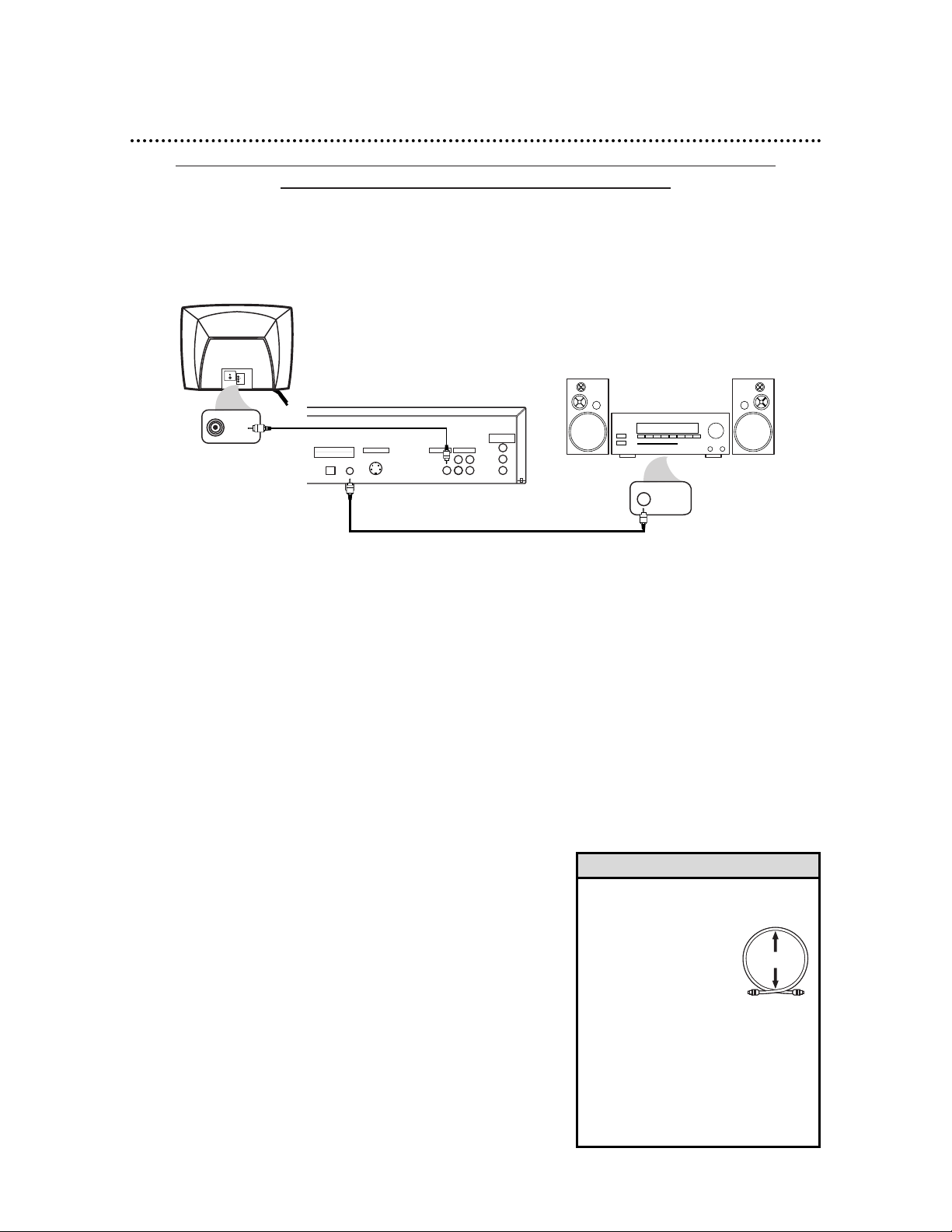
Connecting to a TV and an Amplifier with Coaxial Digital Audio In jacks,
a Mini-Disc Deck or a Digital Audio Tape Deck
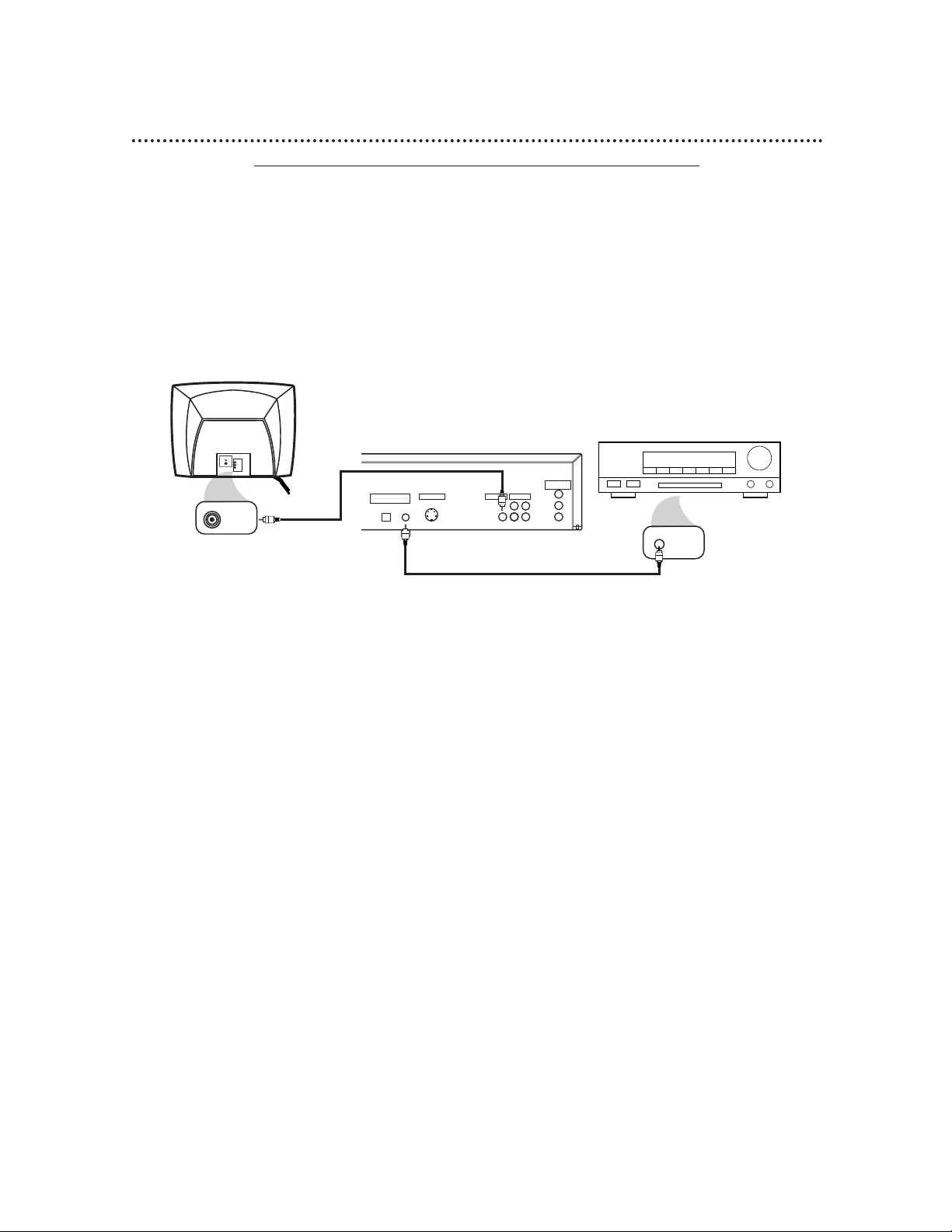
● Use a coaxial digital audio cable or an audio optical cable (not supplied) for this connection.
● If you use the OPTICAL jack, remove the protective cap.
● If the Disc is recorded in 5.1 channel Dolby Digital Surround, you cannot dub the Disc in digital sound using
a Mini-Disc or Digital Audio Tape Deck.
● Set DOLBY DIGITAL and DTS to OFF on the DVD Player. Details are on pages 38-39. If you play a DVD
when the settings are wrong, the sound will be distorted or you may damage the speakers.
DIGITAL AUDIO OUT
PCM / BITSTREAM
AUDIO OUTVIDEO OUTS-VIDEO OUT
COAXIALOPTICAL
COMPONENT
VIDEO OUT
R L
1
2
Y
Cb
Cr
VIDEO
L/MONO
AUDIO
R
in
1
VIDEO IN
COAXIAL DIGITAL
AUDIO IN
Back of TV
(example only)
Back of Amplifier
(example only)
DVD Player
12 Hookups (cont’d)
1
Connect a coaxial digital audio cable to the COAXIAL jack on the DVD Player and to the
COAXIAL DIGITAL AUDIO IN jack on the Amplifier. (Or, you may connect an audio optical cable
to the OPTICAL jack on the DVD Player and to the OPTICAL DIGITAL AUDIO IN jack on the Amplifier.)
2
Connect the supplied yellow video cable to the yellow VIDEO OUT jack on the DVD Player and
to the VIDEO IN jack on the TV. (Or, you may connect an optional component video cable to the COM-
PONENT VIDEO OUT jacks on the DVD Player and to the COMPONENT VIDEO IN jacks on the TV. Or,
you may connect an optional S-Video cable to the S-VIDEO OUT jack on the DVD Player and to the S-VIDEO
IN jack on the TV.)
3
Plug in the Amplifier’s power cord. Turn on the Amplifier and select the Auxiliary IN station.
During Disc playback, you will adjust the volume at the Amplifier. See your Amplifier owner’s manual for
details.
1
2
• Optical cable (not supplied) may be
damaged when bent at acute angles.
Ensure cables are coiled
in loops with a diameter
of 6 inches or more
when storing them.
• Use a cable which is 9.8
feet or shorter.
• Insert cable plugs firmly into the jacks
when making connections.
• If a plug has minor scratches or is
dirty, clean it with a soft cloth before
inserting it into a jack.
• Replace the protective cap on the
OPTICAL jack when it is not in use.
Helpful Hints
4
Plug in the TV’s power cord. Turn on the TV and set it to
the correct Video In channel. During Audio CD playback, you
may check the status of the Disc on your TV screen. During DVD
playback, you will watch the program on the TV. See your TV
owner’s manual for details.
5
Plug in the DVD Player’s power cord. Press the POWER
button to turn on the DVD Player. “HELLO” will appear
briefly on the DVD Player’s display panel. You should see the DVD
logo on the TV briefly. If you do not, check your connections and
make sure the TV is on the correct channel. If there is no disc in
the DVD player, “no DISC” will appear on the display panel.
Minimum 6 in.
in diameter
Page 7
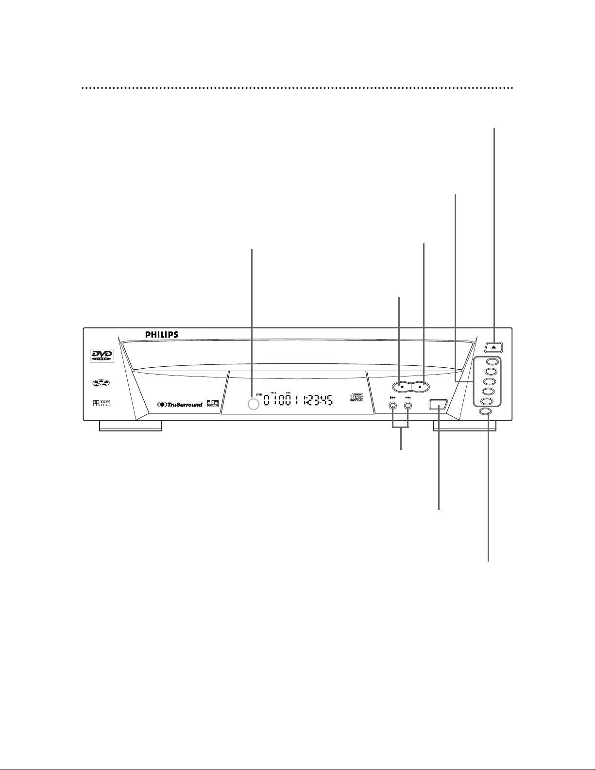
14 Front Panel
DVD/CD 5-DISC CHANGER
SKIP
POWER
PLAY STOP
OPEN/CLOSE
DISC
1
2
3
4
5
SELECT
OPEN/CLOSE Button
Press to open or close the Disc tray.
Details are on page 18.
PLAY Button
Press to start or resume Disc playback. Details are on page 18.
STOP Button
Press to stop Disc playback.
Details are on page 18.
POWER Button
Press to turn the power on and off.
Details are on page 18.
SKIP Buttons
Press to go to subsequent or previous Tracks
or Chapters. Details are on pages 24-25.
Remote Sensor
Receives a signal from your remote
control so you can operate your
DVD Player from a distance.
DISC SELECT Button
Press to select the Disc tray or a Disc
for playback. Details are on page 18.
DISC Number (1-5) Buttons
Press to directly select your desired Disc
tray when the tray is open. Press to select
and play your desired Disc when the tray is
closed. Details are on page 18.
Page 8
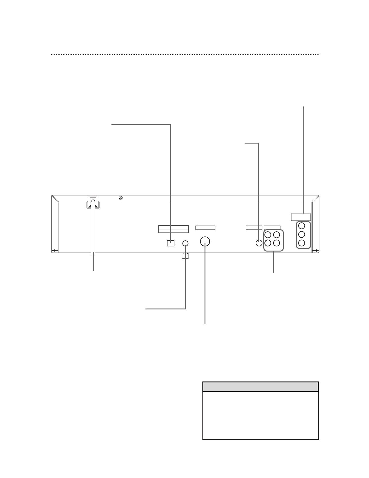
Rear Panel 15
• You only need one audio connection and one
video connection, so you will not have a cable
connected to every jack. For example, if you
are using the S-VIDEO OUT jack, you will not
use the yellow VIDEO OUT jack or the
COMPONENT VIDEO OUT jacks.
Helpful Hint
COMPONENT VIDEO OUT Jacks
Connect an optional component video
cable here and to the component Video
In jacks of a television or stereo. Details
are on pages 10-12.
DIGITAL AUDIO OUT
PCM / BITSTREAM
AUDIO OUTVIDEO OUTS-VIDEO OUT
COAXIALOPTICAL
COMPONENT
VIDEO OUT
R L
1
2
Y
Cb
Cr
AC Power Cord
Connect to a standard AC outlet to
supply power to the DVD Player.
COAXIAL Jack
Connect an optional coaxial
digital audio cable here and to
the Coaxial Digital Audio In
jack of a decoder or amplifier.
Details are on pages 11-12.
S-VIDEO OUT Jack
Connect an optional S-Video
cable here and to the S-Video
In jack of a television. Details
are on pages 9, 11, and 12.
VIDEO OUT Jack
Connect the yellow video
cable (supplied) here and
to the TV’s Video In jack.
Details are on pages 8 and
11-12.
AUDIO OUT Jacks
Connect the supplied audio
cables here and to the Audio In
jacks of a television or stereo.
Details are on pages 8-10.
OPTICAL Jack
Connect an optional audio optical
cable here and to the Optical Digital
Audio In jack of a decoder or amplifier. Details are on pages 11-12.
When the OPTICAL jack is not in
use, make sure its protective cap is in
place.
 Loading...