

Page 1
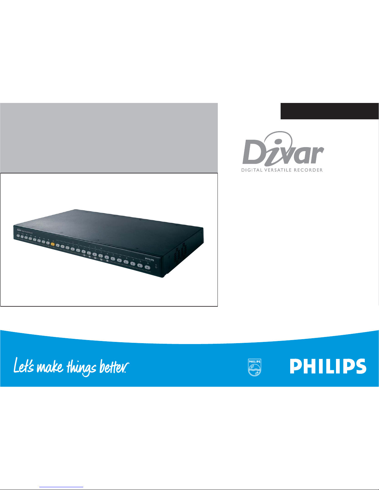
DIVAR DIGITAL VERSATILE
RECORDER
Installation Manual
www.philipscsi.com
Page 2

© 2003 Philips Electronics N.V.
© 2003 Philips Communication, Security & Imaging, Inc.
All Rights Reserved. Philips ® is a registered trademark of Philips Electronics N.V.
Data subject to change without notice
Page 3
Philips Communication, Security & Imaging i
Installation manual
Chapters
1. Introduction
2. Quick install
3. Operating instructions
4. Hardware setup
5. Menu system
6 Using the Configuration Tool
7 Menu default values
8. Technical specifications
Page 4

ii Philips Communication, Security & Imaging
Introduction . . . . . . . . . . . . . . . . . . . . . . . . . . . . . . . . . 1-1
Digital video recorder for security applications . . . . . . . . . . . . . . . . . . . . . . . . 1-1
Features . . . . . . . . . . . . . . . . . . . . . . . . . . . . . . . . . . . . . . . . . . . . . . . . . . . . . . . 1-2
Versions . . . . . . . . . . . . . . . . . . . . . . . . . . . . . . . . . . . . . . . . . . . . . . . . . . . . . . . 1-2
On-screen help . . . . . . . . . . . . . . . . . . . . . . . . . . . . . . . . . . . . . . . . . . . . . . . . . 1-2
Unpacking. . . . . . . . . . . . . . . . . . . . . . . . . . . . . . . . . . . . . . . . . . . . . . . . . . . . . . 1-3
Package contents . . . . . . . . . . . . . . . . . . . . . . . . . . . . . . . . . . . . . . . . . . . . . . . . 1-3
Installation Environment . . . . . . . . . . . . . . . . . . . . . . . . . . . . . . . . . . . . . . . . . . 1-3
Associated Equipment . . . . . . . . . . . . . . . . . . . . . . . . . . . . . . . . . . . . . . . . . . . . 1-4
Quick install . . . . . . . . . . . . . . . . . . . . . . . . . . . . . . . . . 2-1
Primary connections . . . . . . . . . . . . . . . . . . . . . . . . . . . . . . . . . . . . . . . . . . . . . 2-3
Optional connections . . . . . . . . . . . . . . . . . . . . . . . . . . . . . . . . . . . . . . . . . . . . 2-3
Powering up . . . . . . . . . . . . . . . . . . . . . . . . . . . . . . . . . . . . . . . . . . . . . . . . . . . . 2-3
First-time use . . . . . . . . . . . . . . . . . . . . . . . . . . . . . . . . . . . . . . . . . . . . . . . . . . . 2-3
Quick install menu > . . . . . . . . . . . . . . . . . . . . . . . . . . . . . . . . . . . . . . . . . . . . . 2-4
Language . . . . . . . . . . . . . . . . . . . . . . . . . . . . . . . . . . . . . . . . . . . . . . . . . . . 2-4
Time format . . . . . . . . . . . . . . . . . . . . . . . . . . . . . . . . . . . . . . . . . . . . . . . . 2-4
Time . . . . . . . . . . . . . . . . . . . . . . . . . . . . . . . . . . . . . . . . . . . . . . . . . . . . . . . 2-4
Date format . . . . . . . . . . . . . . . . . . . . . . . . . . . . . . . . . . . . . . . . . . . . . . . . . 2-4
Date . . . . . . . . . . . . . . . . . . . . . . . . . . . . . . . . . . . . . . . . . . . . . . . . . . . . . . . 2-4
Active cams . . . . . . . . . . . . . . . . . . . . . . . . . . . . . . . . . . . . . . . . . . . . . . . . . 2-4
Alarm Monitor . . . . . . . . . . . . . . . . . . . . . . . . . . . . . . . . . . . . . . . . . . . . . . 2-4
Recording settings . . . . . . . . . . . . . . . . . . . . . . . . . . . . . . . . . . . . . . . . . . . . 2-4
Network settings . . . . . . . . . . . . . . . . . . . . . . . . . . . . . . . . . . . . . . . . . . . . 2-4
Save & exit . . . . . . . . . . . . . . . . . . . . . . . . . . . . . . . . . . . . . . . . . . . . . . . . . . 2-4
Cancel . . . . . . . . . . . . . . . . . . . . . . . . . . . . . . . . . . . . . . . . . . . . . . . . . . . . . 2-4
Recording settings . . . . . . . . . . . . . . . . . . . . . . . . . . . . . . . . . . . . . . . . . . . . 2-5
Day period . . . . . . . . . . . . . . . . . . . . . . . . . . . . . . . . . . . . . . . . . . . . . . . . . . 2-5
Weekend . . . . . . . . . . . . . . . . . . . . . . . . . . . . . . . . . . . . . . . . . . . . . . . . . . . 2-5
Rec day . . . . . . . . . . . . . . . . . . . . . . . . . . . . . . . . . . . . . . . . . . . . . . . . . . . . 2-5
Rec weekend/night . . . . . . . . . . . . . . . . . . . . . . . . . . . . . . . . . . . . . . . . . . . 2-5
Enable alarm inputs for . . . . . . . . . . . . . . . . . . . . . . . . . . . . . . . . . . . . . . . . 2-5
Alarm input recording . . . . . . . . . . . . . . . . . . . . . . . . . . . . . . . . . . . . . . . . . 2-5
Enable motion for . . . . . . . . . . . . . . . . . . . . . . . . . . . . . . . . . . . . . . . . . . . . 2-6
Motion recording . . . . . . . . . . . . . . . . . . . . . . . . . . . . . . . . . . . . . . . . . . . . 2-6
Approximate recording duration . . . . . . . . . . . . . . . . . . . . . . . . . . . . . . . . 2-6
Network settings . . . . . . . . . . . . . . . . . . . . . . . . . . . . . . . . . . . . . . . . . . . . 2-6
DHCP . . . . . . . . . . . . . . . . . . . . . . . . . . . . . . . . . . . . . . . . . . . . . . . . . . . . . 2-6
DVR name . . . . . . . . . . . . . . . . . . . . . . . . . . . . . . . . . . . . . . . . . . . . . . . . . 2-6
IP address, Subnet mask and Default gateway . . . . . . . . . . . . . . . . . . . . . . 2-6
MAC address . . . . . . . . . . . . . . . . . . . . . . . . . . . . . . . . . . . . . . . . . . . . . . . 2-6
Bandwidth limit . . . . . . . . . . . . . . . . . . . . . . . . . . . . . . . . . . . . . . . . . . . . . . 2-6
Operating instructions . . . . . . . . . . . . . . . . . . . . . . . . . 3-1
Front panel controls . . . . . . . . . . . . . . . . . . . . . . . . . . . . . . . . . . . . . . . . . . . . . 3-2
Indicators. . . . . . . . . . . . . . . . . . . . . . . . . . . . . . . . . . . . . . . . . . . . . . . . . . . . . . 3-2
Keys . . . . . . . . . . . . . . . . . . . . . . . . . . . . . . . . . . . . . . . . . . . . . . . . . . . . . . . . . . 3-2
Primary functions . . . . . . . . . . . . . . . . . . . . . . . . . . . . . . . . . . . . . . . . . . . . . . . 3-3
Alternate functions . . . . . . . . . . . . . . . . . . . . . . . . . . . . . . . . . . . . . . . . . . . . . . 3-4
Viewing pictures . . . . . . . . . . . . . . . . . . . . . . . . . . . . . . . . . . . . . . . . . . . . . . . . 3-5
Viewing . . . . . . . . . . . . . . . . . . . . . . . . . . . . . . . . . . . . . . . . . . . . . . . . . . . . . . . 3-5
Live, playback and search modes . . . . . . . . . . . . . . . . . . . . . . . . . . . . . . . . . . . 3-8
Live mode . . . . . . . . . . . . . . . . . . . . . . . . . . . . . . . . . . . . . . . . . . . . . . . . . . . . . 3-8
Playback mode. . . . . . . . . . . . . . . . . . . . . . . . . . . . . . . . . . . . . . . . . . . . . . . . . . 3-8
Search mode . . . . . . . . . . . . . . . . . . . . . . . . . . . . . . . . . . . . . . . . . . . . . . . . . . . 3-9
Search criteria . . . . . . . . . . . . . . . . . . . . . . . . . . . . . . . . . . . . . . . . . . . . . . . 3-9
Search results . . . . . . . . . . . . . . . . . . . . . . . . . . . . . . . . . . . . . . . . . . . . . . . 3-9
Triggers and alarms . . . . . . . . . . . . . . . . . . . . . . . . . . . . . . . . . . . . . . . . . . . . . 3-10
Alarm inputs . . . . . . . . . . . . . . . . . . . . . . . . . . . . . . . . . . . . . . . . . . . . . . . . . . 3-11
Motion alarm . . . . . . . . . . . . . . . . . . . . . . . . . . . . . . . . . . . . . . . . . . . . . . . . . . 3-11
Video loss alarm . . . . . . . . . . . . . . . . . . . . . . . . . . . . . . . . . . . . . . . . . . . . . . . 3-12
Multiple alarms . . . . . . . . . . . . . . . . . . . . . . . . . . . . . . . . . . . . . . . . . . . . . . . . 3-12
Disk-full alarm . . . . . . . . . . . . . . . . . . . . . . . . . . . . . . . . . . . . . . . . . . . . . . . . . 3-12
Hardware setup . . . . . . . . . . . . . . . . . . . . . . . . . . . . . . 4-1
Rack mounting. . . . . . . . . . . . . . . . . . . . . . . . . . . . . . . . . . . . . . . . . . . . . . . . . . 4-2
Camera connections . . . . . . . . . . . . . . . . . . . . . . . . . . . . . . . . . . . . . . . . . . . . . 4-2
Monitor connections. . . . . . . . . . . . . . . . . . . . . . . . . . . . . . . . . . . . . . . . . . . . . 4-3
Console port connection . . . . . . . . . . . . . . . . . . . . . . . . . . . . . . . . . . . . . . . . . 4-3
Contents
Page 5

Philips Communication, Security & Imaging iii
Keyboard connections . . . . . . . . . . . . . . . . . . . . . . . . . . . . . . . . . . . . . . . . . . . . 4-4
Ethernet connection . . . . . . . . . . . . . . . . . . . . . . . . . . . . . . . . . . . . . . . . . . . . . 4-5
Control port . . . . . . . . . . . . . . . . . . . . . . . . . . . . . . . . . . . . . . . . . . . . . . . . . . . 4-6
External I/O connection . . . . . . . . . . . . . . . . . . . . . . . . . . . . . . . . . . . . . . . . . . 4-7
SCSI connection. . . . . . . . . . . . . . . . . . . . . . . . . . . . . . . . . . . . . . . . . . . . . . . . . 4-8
Power Supply . . . . . . . . . . . . . . . . . . . . . . . . . . . . . . . . . . . . . . . . . . . . . . . . . . . 4-9
Testing . . . . . . . . . . . . . . . . . . . . . . . . . . . . . . . . . . . . . . . . . . . . . . . . . . . . . . . . 4-9
Maintenance . . . . . . . . . . . . . . . . . . . . . . . . . . . . . . . . . . . . . . . . . . . . . . . . . . . . 4-9
Menu system. . . . . . . . . . . . . . . . . . . . . . . . . . . . . . . . . 5-1
Overview of the menu system . . . . . . . . . . . . . . . . . . . . . . . . . . . . . . . . . . . . . 5-2
Accessing the menu from the unit . . . . . . . . . . . . . . . . . . . . . . . . . . . . . . . . . . 5-2
Main Menu . . . . . . . . . . . . . . . . . . . . . . . . . . . . . . . . . . . . . . . . . . . . . . . . . . . . . 5-3
History > . . . . . . . . . . . . . . . . . . . . . . . . . . . . . . . . . . . . . . . . . . . . . . . . . . . . . . 5-4
History Filter . . . . . . . . . . . . . . . . . . . . . . . . . . . . . . . . . . . . . . . . . . . . . . . . 5-4
History List . . . . . . . . . . . . . . . . . . . . . . . . . . . . . . . . . . . . . . . . . . . . . . . . . 5-4
Disk manager > . . . . . . . . . . . . . . . . . . . . . . . . . . . . . . . . . . . . . . . . . . . . . . . . . 5-4
Status Overview . . . . . . . . . . . . . . . . . . . . . . . . . . . . . . . . . . . . . . . . . . . . . 5-4
Protected Recordings . . . . . . . . . . . . . . . . . . . . . . . . . . . . . . . . . . . . . . . . . 5-5
Authenticity Check . . . . . . . . . . . . . . . . . . . . . . . . . . . . . . . . . . . . . . . . . . . 5-5
Stop recording . . . . . . . . . . . . . . . . . . . . . . . . . . . . . . . . . . . . . . . . . . . . . . . 5-5
Storage setup . . . . . . . . . . . . . . . . . . . . . . . . . . . . . . . . . . . . . . . . . . . . . . . . 5-5
Delete Video . . . . . . . . . . . . . . . . . . . . . . . . . . . . . . . . . . . . . . . . . . . . . . . . 5-5
Erase Disk . . . . . . . . . . . . . . . . . . . . . . . . . . . . . . . . . . . . . . . . . . . . . . . . . . 5-5
Time/Date >. . . . . . . . . . . . . . . . . . . . . . . . . . . . . . . . . . . . . . . . . . . . . . . . . . . . 5-6
Synchronize . . . . . . . . . . . . . . . . . . . . . . . . . . . . . . . . . . . . . . . . . . . . . . . . . 5-6
View Settings > . . . . . . . . . . . . . . . . . . . . . . . . . . . . . . . . . . . . . . . . . . . . . . . . . 5-6
Camera setup . . . . . . . . . . . . . . . . . . . . . . . . . . . . . . . . . . . . . . . . . . . . . . . 5-6
Camera controllable . . . . . . . . . . . . . . . . . . . . . . . . . . . . . . . . . . . . . . . . . . 5-7
Sequences . . . . . . . . . . . . . . . . . . . . . . . . . . . . . . . . . . . . . . . . . . . . . . . . . . 5-7
Configure Monitors . . . . . . . . . . . . . . . . . . . . . . . . . . . . . . . . . . . . . . . . . . . 5-7
System Settings > . . . . . . . . . . . . . . . . . . . . . . . . . . . . . . . . . . . . . . . . . . . . . . . . 5-8
Recording Setup . . . . . . . . . . . . . . . . . . . . . . . . . . . . . . . . . . . . . . . . . . . . . 5-8
Playback Setup . . . . . . . . . . . . . . . . . . . . . . . . . . . . . . . . . . . . . . . . . . . . . . . 5-9
Event Setup . . . . . . . . . . . . . . . . . . . . . . . . . . . . . . . . . . . . . . . . . . . . . . . . . 5-9
History Log Setup . . . . . . . . . . . . . . . . . . . . . . . . . . . . . . . . . . . . . . . . . . . 5-10
Local Passwords . . . . . . . . . . . . . . . . . . . . . . . . . . . . . . . . . . . . . . . . . . . . 5-11
Connectivity . . . . . . . . . . . . . . . . . . . . . . . . . . . . . . . . . . . . . . . . . . . . . . . 5-11
Licenses . . . . . . . . . . . . . . . . . . . . . . . . . . . . . . . . . . . . . . . . . . . . . . . . . . . 5-12
Input and output contacts . . . . . . . . . . . . . . . . . . . . . . . . . . . . . . . . . . . . 5-12
Profiles > . . . . . . . . . . . . . . . . . . . . . . . . . . . . . . . . . . . . . . . . . . . . . . . . . . . . . 5-12
Calendar setup . . . . . . . . . . . . . . . . . . . . . . . . . . . . . . . . . . . . . . . . . . . . . 5-12
Profile override . . . . . . . . . . . . . . . . . . . . . . . . . . . . . . . . . . . . . . . . . . . . . 5-13
Profile manager . . . . . . . . . . . . . . . . . . . . . . . . . . . . . . . . . . . . . . . . . . . . . 5-13
System behavior . . . . . . . . . . . . . . . . . . . . . . . . . . . . . . . . . . . . . . . . . . . . 5-13
Using the Configuration Tool . . . . . . . . . . . . . . . . . . . 6-1
Getting started . . . . . . . . . . . . . . . . . . . . . . . . . . . . . . . . . . . . . . . . . . . . . . . . . 6-2
System requirements . . . . . . . . . . . . . . . . . . . . . . . . . . . . . . . . . . . . . . . . . . . . 6-2
Installing the Configuration Tool . . . . . . . . . . . . . . . . . . . . . . . . . . . . . . . . . . . 6-2
Starting the Configuration Tool . . . . . . . . . . . . . . . . . . . . . . . . . . . . . . . . . . . . 6-2
How to Log in . . . . . . . . . . . . . . . . . . . . . . . . . . . . . . . . . . . . . . . . . . . . . . . . . . 6-3
Menu structure differences. . . . . . . . . . . . . . . . . . . . . . . . . . . . . . . . . . . . . . . . 6-4
Introducing the main window . . . . . . . . . . . . . . . . . . . . . . . . . . . . . . . . . . . . . . 6-5
Overview button. . . . . . . . . . . . . . . . . . . . . . . . . . . . . . . . . . . . . . . . . . . . . . . . 6-5
History button. . . . . . . . . . . . . . . . . . . . . . . . . . . . . . . . . . . . . . . . . . . . . . . . . . 6-5
Settings button . . . . . . . . . . . . . . . . . . . . . . . . . . . . . . . . . . . . . . . . . . . . . . . . . 6-5
Service button . . . . . . . . . . . . . . . . . . . . . . . . . . . . . . . . . . . . . . . . . . . . . . . . . . 6-6
Help button . . . . . . . . . . . . . . . . . . . . . . . . . . . . . . . . . . . . . . . . . . . . . . . . . . . . 6-6
Logout button . . . . . . . . . . . . . . . . . . . . . . . . . . . . . . . . . . . . . . . . . . . . . . . . . . 6-6
Using the control buttons . . . . . . . . . . . . . . . . . . . . . . . . . . . . . . . . . . . . . . . . . 6-6
Menu default values . . . . . . . . . . . . . . . . . . . . . . . . . . . 7-1
Technical specifications . . . . . . . . . . . . . . . . . . . . . . . . 8-1
Electrical . . . . . . . . . . . . . . . . . . . . . . . . . . . . . . . . . . . . . . . . . . . . . . . . . . . . . . 8-2
Mechanical . . . . . . . . . . . . . . . . . . . . . . . . . . . . . . . . . . . . . . . . . . . . . . . . . . . . . 8-3
Environmental . . . . . . . . . . . . . . . . . . . . . . . . . . . . . . . . . . . . . . . . . . . . . . . . . . 8-3
Contents
Page 6
iv Philips Communication, Security & Imaging
IMPORTANT SAFETY INSTRUCTIONS
1. Read these instructions - All the safety, operating and installation instructions
should be read before the unit is operated.
2. Keep these instructions - The safety, operating and installation instructions
should be retained for future reference.
3. Heed all warnings - All warnings on the unit and in the operating instructions
should be adhered to.
4. Follow all instructions - All operating and use instructions should be followed.
5. Do not use this apparatus near water - for example, in an unprotected outdoor
installation; or any area which is classified as a wet location.
6. Clean only with a dry cloth - Unplug the unit from the outlet before cleaning.
Do not use liquid cleaners or aerosol cleaners.
7. Do not block any ventilation openings. Install in accordance with the
manufacturer's instructions.
8. Do not install near any heat sources such as radiators, heat registers, stoves, or
other apparatus (including amplifiers) that produce heat.
9. Do not defeat the safety purpose of the polarized or grounding-type plug. A
polarized plug has two blades with one wider that the other. A grounding-type
plug has two blades and a third grounding prong. The wide blade or third prong
are provided for your safety. If the provided plug does not fit into the outlet,
consult an electrician for replacement of the obsolete outlet.
10. Protect the power cord from being walked on or pinched particularly at
plugs, convenience receptacles, and the point where they exit from the apparatus.
SAFETY PRECAUTIONS
This label may appear on the bottom of the unit due to space limitations.
Attention: Installation should be performed by
qualified service personnel only in accordance with the
National Electrical Code or applicable local codes.
CAUTION: TO REDUCE THE RISK OF ELECTRICAL
SHOCK, DO NOT OPEN COVERS. NO USER
SERVICEABLE PARTS INSIDE. REFER SERVICING TO
QUALIFIED SERVICE PERSONNEL.
WARNING
TO REDUCE THE RISK OF FIRE OR ELECTRIC
SHOCK, DO NOT EXPOSE THIS APPARATUS
TO RAIN OR MOISTURE.
Power Disconnect. Units have power supplied
whenever the power cord is inserted into the power
source. The power cord is the main power disconnect
for all units.
The socket outlet shall be installed near the
equipment and shall be easily accessible.
CAUTION
RISK OF ELECTRIC
SHOCK. DO NOT OPEN!
The exclamation point within an equilateral triangle
is intended to alert the user to presence of important
operating and maintenance (servicing) instructions in
the literature accompanying the appliance.
The lightning flash with an arrowhead symbol within
an equilateral triangle is intended to alert the user to the
presence of uninsulated "dangerous voltage" within the
product's enclosure that may be of sufficient magnitude
to constitute a risk of electric shock to persons.
Page 7

Philips Communication, Security & Imaging v
11. Only use attachments/accessories specified by the manufacturer.
12. Use only with the cart, stand, tripod, bracket, or table specified by the
manufacturer, or sold with the apparatus. When a cart is used, use caution when
moving the cart/apparatus combination to avoid injury from tip-over.
13. Unplug this unit during lightning storms or when unused for long periods of
time.
14. Refer all servicing to qualified service personnel. Servicing is required when
the apparatus has been damaged in any way, such as power-supply cord or plug is
damaged, liquid has been spilled or objects have fallen into the apparatus, the
apparatus has been exposed to rain or moistue, does not operate normally, or has
been dropped.
15. Moving - Disconnect the power before moving the unit. The unit should be
moved with care. Excessive force or shock may result in damage to the unit and
the hard disk drives.
16. Power Sources - This unit should be operated only from the type of power
source indicated on the marking label. If you are not sure of the type of power
supply you plan to use, consult your appliance dealer or local power company.
17. Overloading - Do not overload outlets and extension cords as this can result
in a risk of fire or electric shock.
18. Object and Liquid Entry - Never push objects of any kind into this unit
through openings, as they may touch dangerous voltage points or short out parts
that could result in a fire or electric shock. Never spill liquid of any kind on the
unit.
19. Replacement Parts - When replacement parts are required, be sure the service
technician has used replacement parts specified by the manufacturer or have the
same characteristics as the original part. Unauthorized substitutions may result in
fire, electric shock, or other hazards.
20. Safety Check - Upon completion of any service or repairs to this unit, ask the
service technician to perform safety checks to determine that the unit is in proper
operating condition.
21. Coax Grounding - If an outside cable system is connected to the unit, be sure
the cable system is grounded. U.S.A. models only--Section 810 of the National
Electrical Code, ANSI/NFPA No.70-1981, provides information with respect to
proper grounding of the mount and supporting structure, grounding of the coax
to a discharge unit, size of grounding conductors, location of discharge unit,
connection to grounding electrodes, and requirements for the grounding
electrode.
Page 8
vi Philips Communication, Security & Imaging
FCC & ICES INFORMATION
(U.S.A. and Canadian Models Only)
This is a Class B product. This device complies with Part 15 of the FCC rules.
Operation is subject to the following two conditions: (1) this device may not
cause harmful interference, and (2) this device must accept any interference
received, including interference that may cause undisired operation.
Reference
Definition of terms
Cameo: Single camera picture in a multiscreen display.
Dwell time: The length of time that an alarm indicator continues to operate
after the event causing it has occurred. The length of time a single
image of a sequence is shown.
Full-screen: A display that only shows one picture occupying a full screen.
Multiscreen: The division of a display screen so that it shows a certain number
of cameras at the same time.
Sequence: Camera pictures shown one after the other in time either in full-
screen or quad modes.
Quad: Four camera pictures shown on one display screen.
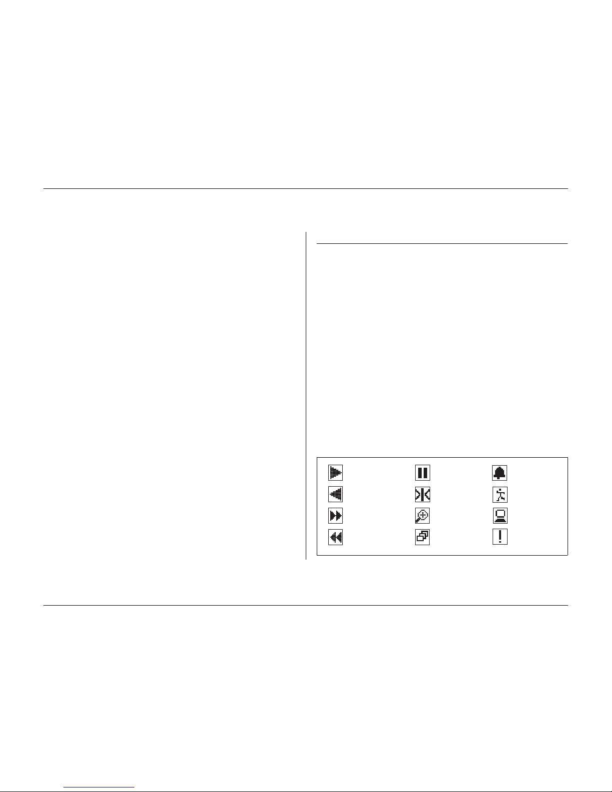
Icons shown on the screen
Play forward
Play reverse
Fast forward
Fast reverse
Pause
Freeze
Zoom
Sequence
Alarm
Motion
Network
Error
Page 9

Philips Communication, Security & Imaging 1-1
CHAPTER 1
Introduction
Digital video recorder for security applications
The Divar is a video recording system that can record multiple camera signals
while simultaneously providing live multiscreen viewing and playback. It
combines the functionality of a digital recorder with a multiplexer and a
switcher.
The unit has comprehensive search and playback facilities for viewing stored
video. Once set up, all recording takes place in the background without
requiring operator intervention. Maximum recording rates of 60 (NTSC) and
50 (PAL) images per second in total are guaranteed with unsynchronized
cameras. The recording rate and quality are selectable per camera.
All models have extensive alarm handling functions and telemetry control. Alarm
functions include motion detection in user-definable areas of the image on any
camera input.
The unit can be easily operated and programmed via the front panel control keys
and on-screen display menu system. One monitor output provides full-screen,
quad and multiscreen viewing; another spot/alarm monitoring. A keyboard can
be connected for PTZ control and to improve the ease-of-use.
Via a network, the Control Center PC-application can be used for live viewing,
playback and configuration. The Divar includes an authenticity check for both
local and remote playback. A dedicated PC player is provided for playback of
secure video files.
The PC-based Configuration Tool facilitates the setup of the unit.
Page 10
Introduction
1-2 Philips Communication, Security & Imaging
Looping auto-terminating video inputs, video outputs, alarm inputs and
outputs, and remote control connectors are on the rear panel. The two monitor
outputs provide CVBS video signals in either NTSC or PAL. Monitor A displays
full-screen or multiscreen digital pictures that can be frozen and zoomed.
Monitor B displays live full-screen pictures.
Features
The Divar has the following features:
• 6, 9 or 16 looped-through, auto-terminating camera inputs.
• Simultaneous recording and playback.
• Internal hard disk video storage.
• Narrow SCSI port for external SCSI storage expansion.
• 10/100Base-T Ethernet port for Ethernet connection and networking.
• RS232 serial port for serial communications.
• External keyboard input and output ports for keyboard connection and
system expansion.
• Dual monitor outputs.
• Full-screen and various multiscreen display capabilities in live and playback
modes.
• Spot monitor output with sequencing and OSD.
• Motion detection.
• 16 switching (alarm) inputs and 4 alarm outputs.
• Video loss detection.
• Audible alarm.
• Pan, tilt and zoom camera control.
Ver si ons
There are three Divar models; 6-channel, 9-channel and 16-channel, each with
various storage capacities. This manual describes the 16-channel version. Both 6channel and 9-channel versions operate in exactly the same way except that fewer
cameras can be connected, there are fewer camera keys and the number of
multiscreen views is reduced.
On-screen help
On-screen context-sensitive help is available for all topics. Just press the yellow
ALT key for at least one second to see the help text associated with your
current activity. Press the escape key to exit help.
For more information please visit:
www.philipscsi.com
Page 11
Introduction
Philips Communication, Security & Imaging 1-3
Unpacking
Check the package for visible damage. If any items appear to have been damaged
in shipment, notify the shipping company. Unpack carefully. This is electronic
equipment and should be handled with care to prevent damage to the unit. Do
not attempt to use the unit if any components are damaged. If any items are
missing, notify your Customer Service Representative or Philips CSI Sales
Representative.
The shipping carton is the safest container in which to transport the unit. Save it
and all packing materials for future use. If the unit must be returned, use the
original packing materials.
Package contents
Check for the following items:
• Digital Video Recorder (Divar 16, Divar 9 or Divar 6 unit)
•Quick reference guide
• Divar operation manual
• Divar Control Center and Archive Player operation manual
• Installation manual (this manual)
• A 25-pin D-type connector board with screw terminals (used for switching
and alarm connections)
• A 15-pin D-type connector board with screw terminals (used for PTZ
connections)
• Power supply cord
• Network cross-over cable
• Serial RS232 cross-over (null-modem) cable
• Divar loop-through cable
• Rack mounting kit
• A CD-ROM with the software and the manuals.
Installation Environment
Mounting:
The Divar is supplied as a desktop unit. If desired, the unit may be
rack mounted using the rack mounting kit supplied with the unit.
Ventilation:
Ensure that the location planned for the installation of the unit is
well ventilated. Take note of the locations of the cooling vents in the unit's
enclosure and ensure that they are not obstructed.
Temperature:
Observe the unit's ambient temperature specifications when
choosing an installation space. Extremes of heat or cold beyond the specified
operating temperature limits may cause the unit to fail. Do not install the unit
on top of hot equipment.
Power Supply:
Ensure that the site's AC power supply is stable and within the
rated voltage of the unit. If the site's AC power is likely to have spikes or power
dips, use power line conditioning or an uninterruptable power supply (UPS).
Page 12

Introduction
1-4 Philips Communication, Security & Imaging
Associated Equipment
A typical system could contain the following components (not included with the
unit):
• A primary monitor for multiscreen monitoring (monitor A).
• A second monitor for spot/alarm monitoring (monitor B).
• Cameras with 1 Vpp composite video outputs.
• 75-ohm BNC connectors and video coaxial cable for connecting the video
signals.
• AC power supply outlet for the unit that allows for secure isolation. (The
unit has no on/off switch for security reasons.)
• A keyboard (KBD-Digital).
• PC for Control Center and Configuration Tool applications.
• Pan/tilt/zoom control units.
• SCSI cable for connection to external storage devices.
• External storage devices (DVAD LP Storage Array or DVAS RAID Storage
Array).
• Video Manager for system expansion.
Page 13

Philips Communication, Security & Imaging 2-1
CHAPTER 2
Quick install
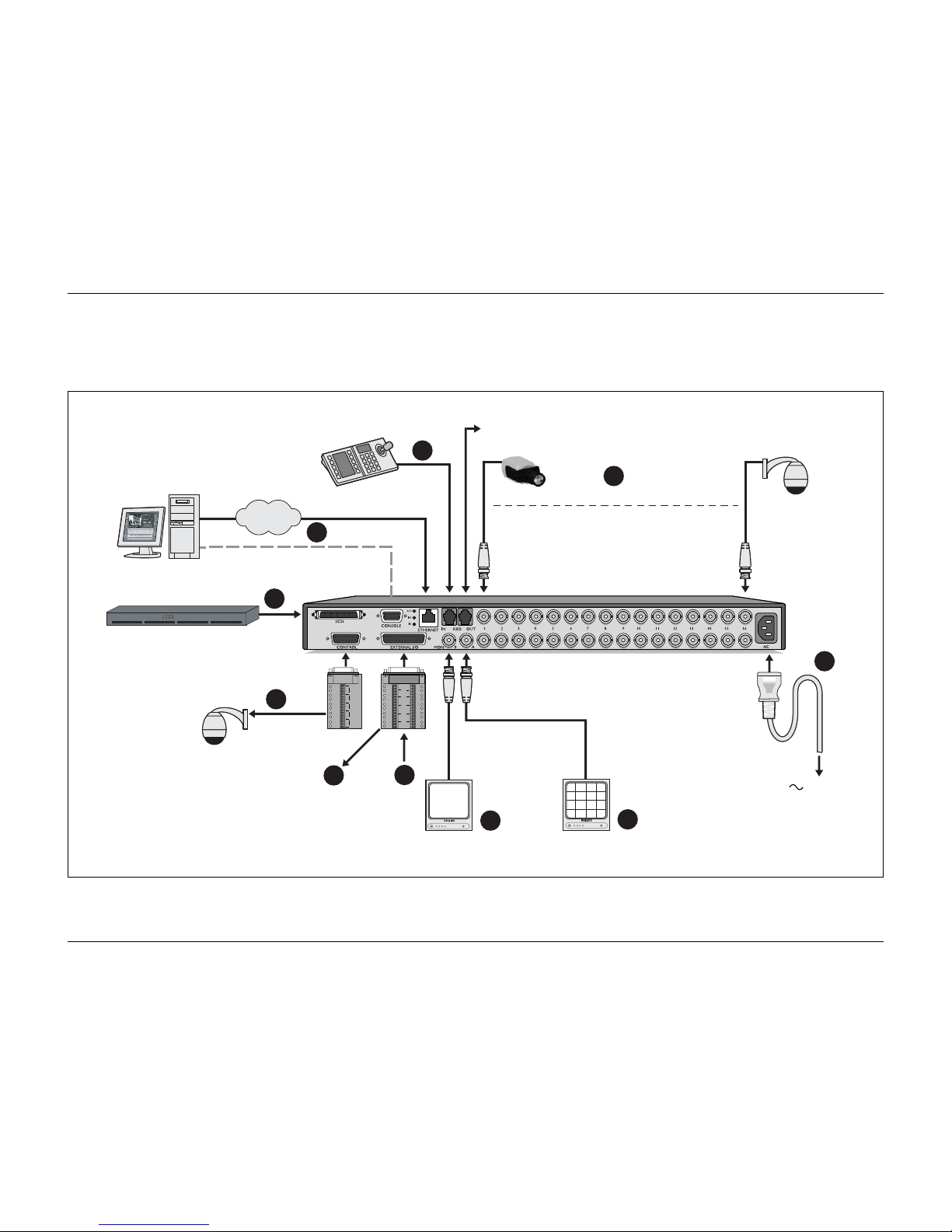
This chapter gives instructions on how to quickly get the unit operational. Make
the connections described on the following pages and then enter the relevant
data in the quick install menu.
The Quick Install menu appears the first time you start the unit. When you have
entered the relevant information the unit will be operational.
Page 14
Quick install
2-2 Philips Communication, Security & Imaging
Quick connection
x16*
AutoDome
LAN / WAN
RS232
VIDEO
IN
VIDEO
OUT
VIDEO
OUT
VIDEO
IN
1
6
3
11
2
7
5
4
9
8
1A
1B
2A
2B
R
E
L
A
Y
3A
3B
4A
4B
GND
1
2
GND
9
10
3
4
GND
11
12
5
6
GND
13
14
7
8
15
16
IN
IN
IN
IN
+
SHIELD
CTRL 1
SHIELD
+
SHIELD
CTRL 2
+
SHIELD
CTRL 3
+
SHIELD
CTRL 4
+
SHIELD
CTRL 5
110 - 240 Vac
Storage Array PHILIPS
A
B
DIVAR / 390 Ohm
AutoDome
*can be 6, 9 or 16 depending on model
Page 15
Quick install
Philips Communication, Security & Imaging 2-3
Primary connections
1.
Connect the cameras to the BNC loop-through camera inputs (automatically
terminated).
2.
Connect monitor A to the BNC output MON A.
Optional connections
3.
Connect monitor B to the BNC output MON B.
4.
Connect up to 16 (alarm) inputs via the supplied 25-pin D-type connector board.
5.
Connect up to 4 alarm output relays via the supplied 25-pin D-type connector
board.
6.
Connect a keyboard unit to the KBD IN socket.
7.
Connect a pan/tilt/zoom control unit via the supplied 15-pole D-type connector
board
8.
Connect to your network via the Ethernet port or use the RS232 connector to
connect directly to a PC serial port.
9.
Connect an external storage unit via the narrow 50-pin high density SCSI-2 port.
Powering up
10.
Switch on all connected equipment.
11.
Connect the power cord to the unit.
First-time use
The unit starts with a multiscreen display. The Quick install menu opens the
first time you use the unit. Fill in these basic settings to get the unit operational.
Select the
Install
item to save your settings and close the menu. When you close
the Quick install menu, the unit begins recording automatically.
To open the Quick install menu at any other time:
1.
Press the ALT key to enter the alternate function mode.
> The ALT indicator lights.
2.
Press the menu key .
> The main menu appears full-screen on monitor A.
Select the System settings menu and then the Quick install submenu.
Navigating
• Use the arrow keys to move through a menu or list.
• Use the select key to select a submenu or item.
• Use the escape key to go back or to switch off the menu.
Page 16
Quick install
2-4 Philips Communication, Security & Imaging
Q
UICK INSTALL MENU
>
>> Language
• Select the language for the menu from the list.
>> Time format
• Select either a 12 or a 24 hour clock format.
>> Time
• Fill in the actual time.
>> Date format
• Select from three date formats which show either the month (MM), the
day (DD) or the year (YYYY) first.
>> Date
• Fill in the actual date.
>> Active cams
• Select the cameras you wish to activate. Only activated cameras are
configured after exiting the Quick Install menu. Press the camera keys to
select or deselect a camera. A check mark means selected.
>> Alarm Monitor
• Select the monitor on which input alarm messages are displayed.
>> Recording settings
• Opens recording settings submenu to fill in the basic recording settings
for the day and weekend/night profiles.
>> Network settings
• Opens network settings submenu to fill in the settings that control the
behavior of the unit with respect to a network.
>> Save & exit
• Select this item to load the settings you have made into the unit and exit
the Quick Install.
>> Cancel
• Select this item to exit the Quick Install without saving.
QUICK INSTALL
LANGUAGE ENGLISH
TIME FORMAT 24-HOUR
TIME 19:45:00
DATE FORMAT YYYY-MM-DD
DATE 2002-06-20
1 2 3 4 5 6 7 8 9 10 11 12 13 14 15 16
ACTIVE CAMS
ALARM MONITOR MON A ONLY
RECORDING SETTINGS >
NETWORK SETTINGS >
SAVE & EXIT >
CANCEL
Page 17
Quick install
Philips Communication, Security & Imaging 2-5
>> Recording settings
>> Day period
• Fill in a start time and an end time to define the period during which the
day profile is active.
• The weekend/night profile is active for the rest of the 24-hour period.
>> Weekend
• When a day is defined as a weekend day, then the weekend/night profile is
active that whole day.
• Define the weekend as either Saturday and Sunday or just Sunday.
• Select none if you wish the weekend to be the same as the other days of
the week.
>> Rec day
• Select the normal recording speed to be used for each of the activated
cameras during the day profile.
• The Images Per Second (IPS) rates available for PAL range from Never, 0,
1/10 (one image every 10 seconds), up to 25 IPS.
• The Images Per Second (IPS) rates available for NTSC range from Never,
0, 1/10 (one image every 10 seconds), up to 30 IPS.
• Set the recording speed to NEVER to not record a camera at all. No prealarm recording is done and the camera cannot be viewed over the
network.
>> Rec weekend/night
• Select the normal recording speed to be used for each of the activated
cameras during the weekend/night profile.
• The Images Per Second (IPS) rates available for PAL range from Never, 0,
1/10 (one image every 10 seconds), up to 25 IPS.
• The Images Per Second (IPS) rates available for NTSC range from Never,
0, 1/10 (one image every 10 seconds), up to 30 IPS.
• Set the recording speed to NEVER to not record a camera at all. No prealarm recording is done and the camera cannot be viewed over the
network.
>> Enable alarm inputs for
• Select the profiles during which alarm inputs are enabled.
• Choose day only, weekend/night only, both day and weekend/night or
none.
>> Alarm input recording
• An activated input alarm can increase the recording speed of a camera.
Select the recording speed to be used when an input is activated.
• The camera with the number that corresponds to the alarm input number
is recorded at the speed you set.
RECORDING SETTINGS
DAY PERIOD 8:00 18:00
WEEKEND SAT AND SUN
REC DAY 1 IPS/CAM
REC WEEKEND/NIGHT 2 IPS/CAM
ENABLE ALARM INPUTS FOR DAY/NIGHT
ALARM INPUT RECORDING 12.5 IPS/INPUT
ENABLE MOTION FOR NIGHT
1 2 3 4 5 6 7 8 9 10 11 12 13 14 15 16
MOTION RECORDING 5 IPS/CAM
APPROX. REC. DURATION 036 HOURS
Page 18
Quick install
2-6 Philips Communication, Security & Imaging
>> Enable motion for
• Select the profiles during which motion events are enabled Choose day,
weekend/night, both day and weekend/night or none.
• Press the camera keys to select or deselect the cameras for which motion
should be enabled. A check mark means enabled.
>> Motion recording
• A camera can be recorded at an increased recording speed when motion is
detected. Select the recording speed to be used for each of the cameras
when motion is detected.
>> Approximate recording duration
• This is an estimate of the recording duration based on the total amount of
storage space available and the recording setup. For event recording, the
following parameters are used:
- During the day, one camera is in input alarm recording 5% of the
time and every motion enabled camera is in motion recording 10% of
the time.
- During the night and weekend, one camera is in input alarm
recording 1% of the time and in motion recording for 3% of the time.
>> Network settings
>> DHCP
• Set DHCP to Yes to have IP address, subnet mask and default gateway
assigned automatically by the network server. The actual values are
displayed.
>> DVR name
• Enter a Divar name to be used in the network.
>> IP address, Subnet mask and Default gateway
• Fill in the IP, subnet mask and default gateway addresses when DHCP is
set to No.
>> MAC address
• The MAC address is read only.
>> Bandwidth limit
• Restrict the network bandwidth by entering an MBPS between 0 and 100
for the bandwidth limit.
NETWORK SETTINGS
DHCP NO
DVR NAME DIVAR
IP ADDRESS 192.168. 10.2
SUBNET MASK 255.255.255. 0
DEFAULT GATEWAY 0. 0. 0. 0
MAC ADDRESS 00:00:00:00:00:00
BANDWIDTH LIMIT 100 MBPS
Page 19

Philips Communication, Security & Imaging 3-1
CHAPTER 3
Operating instructions
The instructions in this chapter explain the purpose of the front panel keys. The
functions available can be limited by setting passwords.
An administrator has access to many more functions in the menu. Refer to
Chapter 5 - Advanced Menu Setup for a full list of available menu items.
Page 20
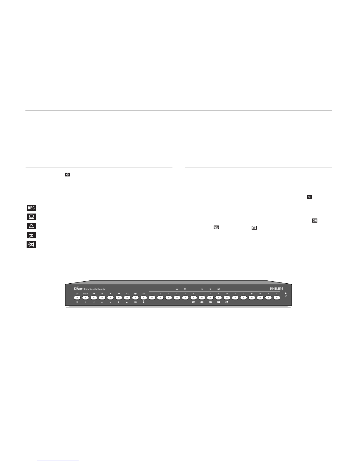
Operating instructions
3-2 Philips Communication, Security & Imaging
Front panel controls
Indicators
The power indicator lights to indicate that power is being supplied to the
unit.
The indicators across the top of the unit light or flash to alert you to various
operating conditions.
Record - lights when the unit is recording video.
Network - lights when a remote user is connected to the unit.
Alarm - flashes when an alarm is detected.
Motion - flashes when motion is detected in a camera signal.
Video loss - flashes when a video loss condition is detected for a
camera input.
Keys
The keys on the front panel can be used for controlling primary functions or
alternate functions. Symbols for the primary functions are shown above the keys.
Symbols for the alternate functions are shown below the keys.
The alternate functions are activated by first pressing the ALT key and then
the desired key. When the alternate function mode is active, the light below the
ALT key is lit.
The unit automatically exits the alternate mode if the monitor A key ,
monitor B key or sequence key is pressed. When in a menu, the keys
operate according to their alternate function.
Page 21
Operating instructions
Philips Communication, Security & Imaging 3-3
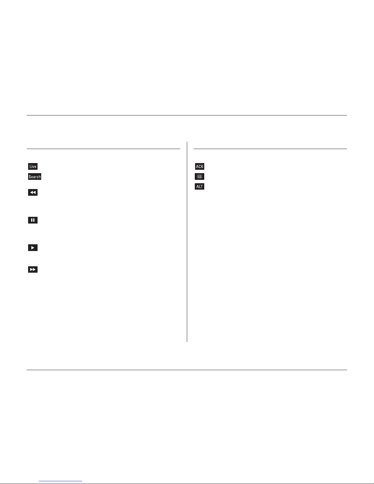
Primary functions
(light below ALT key off )
Live key - press to switch to live viewing.
Search key - press to open a search menu to look for recorded
events.
Reverse key - in live mode, press to start reverse playback of
recordings for the displayed cameras.
- in playback mode, press to speed up rewind.
- in pause mode, press to step back one frame.
Pause key - in live mode, press to freeze a camera picture.
- in the playback mode, press to freeze playback
picture; press for longer than one second to protect
recordings.
Play key - in live mode, press to resume playback from the last
used playback position.
- in pause mode, press to resume playback.
Fast forward - in live mode, press to start playback from one
minute earlier.
- in playback mode, press to speed up the playback
rate.
- in pause mode, press to step forward one frame.
ACK key - press when flashing to acknowledge an alarm.
Multiscreen key- press to see different monitor display layouts.
ALT key - switches the front panel keys between a normal
function and an alternate function (shown below the
key).
- press for longer than one second to get on-screen
help.
1 - 16 Camera keys - press to see a full-screen display of the camera’s
picture.
- in the menu mode, press to select the camera or
enter a password.
Page 22
Operating instructions
3-4 Philips Communication, Security & Imaging
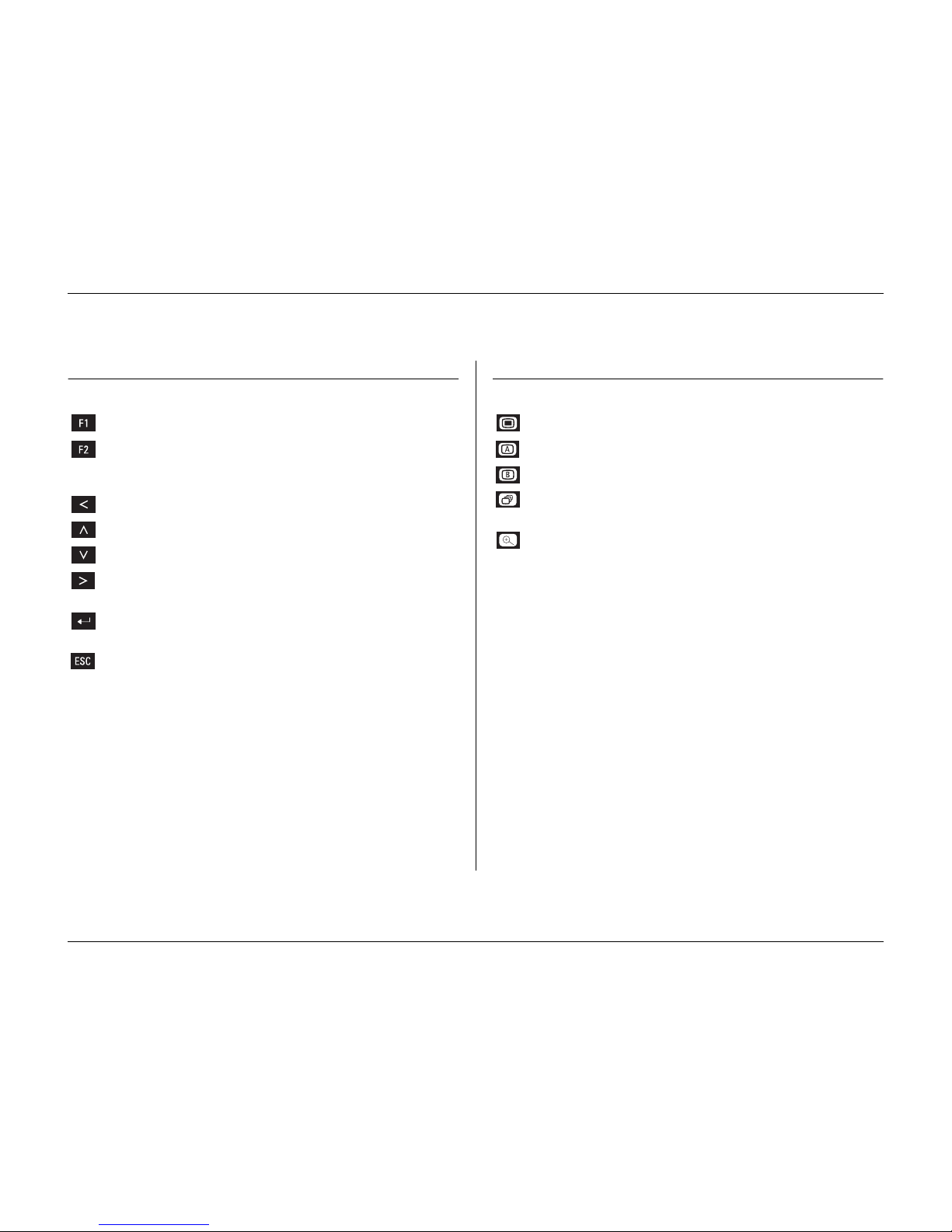
Alternate functions
(light below ALT key is lit)
F1 key - restores defaults in active menu.
F2 key - is assigned a specific function in some submenus.
Arrow keys: - move around through menu items or values.
-Left
-Up
-Down
-Right
Select key - selects a submenu or menu item, or saves selections
made in menus.
ESC key - press to return to previous level or to exit menu
system without saving.
- press to leave help system.
Menu key - opens the menu system.
Mon A key - assigns front panel keys to monitor A.
Mon B key - assigns front panel keys to monitor B.
Sequence key - view cameras in sequence on full-screen or quad
displays.
Zoom key - zooms in on the active camera display (full-screen or
active cameo).
Page 23
Operating instructions
Philips Communication, Security & Imaging 3-5
Viewing pictures
The unit has two monitor outputs, A and B. The way in which these monitors
display pictures depends on how the system has been set up.
Monitor A
Monitor A is the main monitor. It shows full-screen, quad or multiscreen live or
playback camera pictures. Status messages, alarms, motion, and video loss
warnings are also displayed on this monitor. When the menu system is activated
it is displayed on this monitor.
Monitor B
Monitor B displays a single full-screen picture of a selected camera or a sequence
of full-screen pictures. When an alarm or motion input is detected, the camera
picture with the Alarm/Motion indicator can be displayed on monitor B. When
multiple alarms or motion occur, camera pictures are sequenced on monitor B.
Selecting a monitor to control
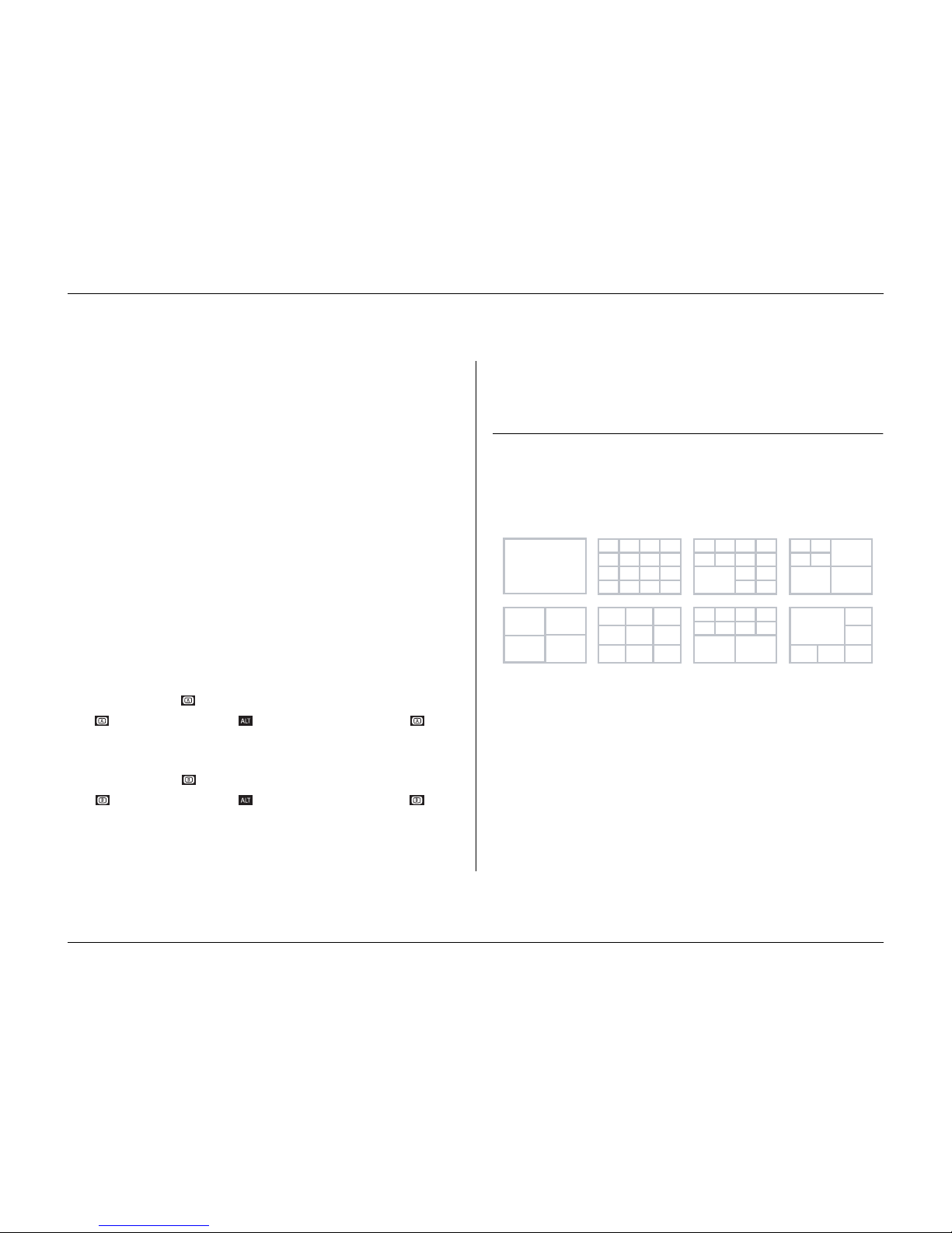
To control the display on monitor A:
1.
Check that the light on the front panel is lit.
2.
If is not lit, press the ALT key and then press the monitor A key .
To control the display on monitor B:
1.
Check that the light on the front panel is lit.
2.
If is not lit, press the ALT key and then press the monitor B key .
Viewing
The drawing shows all possible views for monitor A. Some multiscreen views
may have been disabled during set-up. The Divar model and the number of
connected cameras can also influence the multiscreen views available.
The quad mode can have 4 different quad screens that can be shown in sequence
to display 16 camera pictures.
1 2 3 4
8765
9
13 14
10 11 12
1615
1
4
7
2 3
5 6
8 9
1 2 3 4
8765
10 11
1312
9
1 2 3 4
8765
9 10
1 2
54
6 7
3
5
6
4
4x4
3x3 8+2
12+1 4+3
5+1
1
3
1 2
4
1
2
3
Page 24
Operating instructions
3-6 Philips Communication, Security & Imaging
Multiscreen
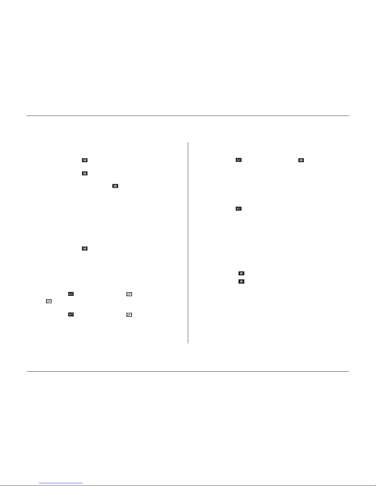
To view different multiscreen displays on monitor A:
1.
Press the multiscreen key .
> A multiscreen display of camera pictures appears on monitor A.
2.
Press the multiscreen key again to go to the next programmed multiscreen
view.
> If you continue to press the multiscreen key , the unit cycles through all enabled
multiscreen views.
Full-screen
To view a full-screen shot of a camera:
1.
Press a camera key.
> A full-screen shot of the camera you selected appears.
> The camera key of the selected camera lights (green).
2.
Press the multiscreen key to go back to your previous multiscreen view on
monitor A.
Sequence
To view a sequence of live camera pictures of several cameras:
1.
Press the ALT key and then the sequence key .
> The indicator lights.
> A sequence of camera pictures appears, each for a pre-programmed dwell time .
2.
Press the ALT key and then the sequence key to stop sequencing.
> Zooming, pressing the multiscreen key or selecting a single camera also stops
sequencing.
Cameo assignment
Assigning cameras to cameos in a multiscreen view:
1.
Press the ALT key and then the multiscreen key .
> The multiscreen key indicator flashes.
> The border around the active cameo is green.
> The camera key of the camera shown in the active cameo lights (green).
2.
Use the arrow keys if you wish to select a different cameo.
3.
Press a camera key to display that camera’s picture in the active cameo.
> The camera is assigned and the following cameo becomes active.
4.
Continue to press camera keys to assign camera pictures to cameos.
5.
Press the ALT key to interrupt cameo assignment and exit the assignment
mode.
> The assignment mode is automatically ended when the last cameo has been assigned.
The cameo assignment that you make is used in playback mode as well as in live
mode.
Image freeze
Freezing a camera shot on monitor A:
1.
Press the pause key to freeze the picture in the active cameo.
2.
Press the pause key again to return to live viewing.
If you are viewing a camera picture in full-screen mode, then this picture is
frozen. The zoom function can be used on a frozen picture. If you change
viewing mode, any frozen pictures are released.
Page 25
Operating instructions
Philips Communication, Security & Imaging 3-7
Zoom
To zoom in on a camera picture:
1.
Press the ALT key .
> The ALT indicator lights.
2.
Press the zoom key .
> The zoom indicator lights.
> The picture is enlarged by a factor of 2.
3.
Use the arrow keys to select the area of the picture to be displayed.
4.
Press the zoom key again to zoom in further.
> The picture is enlarged by a factor of 4.
5.
Use the arrow keys to select the area of the picture you want to see.
6.
Press the zoom key again to return to a full picture and leave the zoom
mode.
> The zoom indicator no longer lights.
7.
Press the ALT key to return the keys to normal operation.
> The ALT indicator no longer lights.
Page 26
Operating instructions
3-8 Philips Communication, Security & Imaging
Live, playback and search modes
Live mode
The live mode is the normal operating mode of the unit where you watch live
pictures from the cameras. From the live mode you can switch to the search
mode, the playback mode or to the system menu.
Access to search and playback functions may require a password. Discuss this
with your administrator.
Press the search key to switch to the search mode. The search menu opens.
To enter the playback mode use one of the following keys:
• Press the rewind key to start reverse playback of recordings for the
displayed cameras.
• Press the forward key to start playback from one minute earlier.
• Press the play key to resume playback from the last selected playback
position.
Press the live key to switch back to live viewing. An alarm also switches the
unit back to live viewing.
Playback mode
In playback mode the video control keys operate as follows:
• Press the rewind key to start reverse play of recordings. Pressing it again
and again increases the display rate to a maximum and then back to normal
speed again. Press the rewind key in the pause mode to step back one
field at a time.
• Press the pause key to freeze the picture.
• Press the forward key to start forward playback of recordings. Pressing it
again and again increases the display rate to a maximum and then back to
normal speed again. Press the forward key in the pause mode to step
forward one field at a time.
• Press the play key to resume playback.
Press the live key to switch back to live viewing or press the search key
to switch to the search mode. In both cases, playback stops.
Protecting a video recording
1.
Press the pause key for longer than one second during playback to mark the
beginning of a protected recording.
> A dialog window appears.
> The time and date of the marker at which protection of the video starts is shown.
2.
Press the select key to continue playing the video you wish to protect.
3.
During playback, press the pause key for longer than one second again to
mark the end of a protected recording.
> A dialog window appears.
> The date and time of the beginning and end markers of the video to be protected is
shown.
4.
Select Ye s to protect the marked video from deletion.
Page 27
Operating instructions
Philips Communication, Security & Imaging 3-9
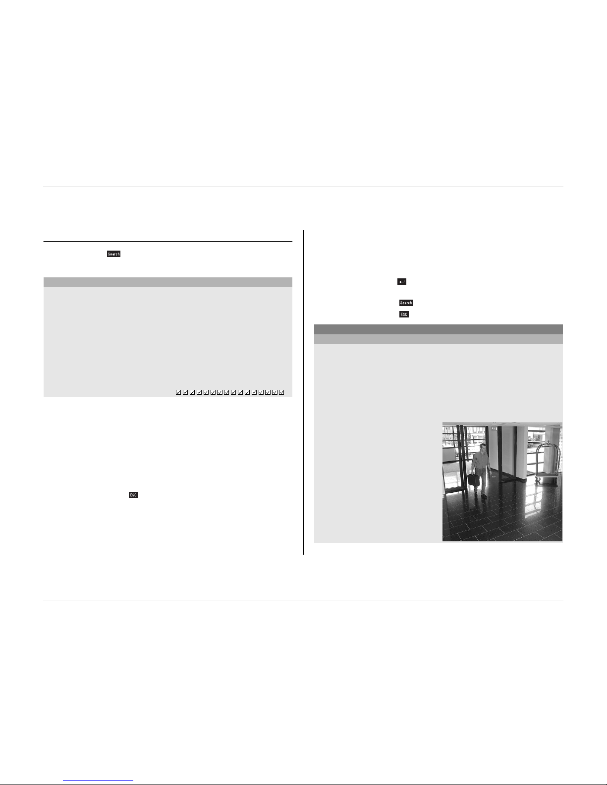
Search mode
Press the search key to open the search menu. Use the search menu to
search for stored video recordings.
>> SEARCH CRITERIA
• Set the
Event filter
to search for only alarm events, only motion events or
both.
•Set to
None
so that the search is not restricted by events.
• Fill in a time and date from where to start the search.
• Specify the cameras to search for. The selected cameras are shown at the
bottom of the menu with a check mark.
• Press a camera key to change the selection.
•Select
Search results
to see a list of results.
• Press the escape key to exit the search mode and return to the
previous mode.
>> SEARCH RESULTS
• The recording fitting the filter and closest to the start date and time is
shown first.
• Use the up/down arrow keys to move through a long list. The selected
recording is shown.
• Press the select key for a full-screen playback of the selected
recording.
• Press the search key during playback to return to the list.
• Press the escape key to return to the filter menu.
PLAYBACK SEARCH
SEARCH EVENT FILTER ALARM/MOTION
CAMERA ALL
START TIME 2002-03-14 13:00
SEARCH RESULTS >
DISK CONTENTS
EARLIEST TIME 2002-03-14 14:00
LATEST TIME 2002-06-19 20:23
1 2 3 4 5 6 7 8 9 10 11 12 13 14 15 16
FILTER
PLAYBACK SEARCH
SEARCH RESULTS
CAMERA 1 MOTION 2002-03-14 15:00:17
Page 28
Operating instructions
3-10 Philips Communication, Security & Imaging
Triggers and alarms
Various types of events can change the way the unit works. These events can be:
• An alarm input signal applied to the unit.
• Motion detection in a camera signal.
• A loss of video from one of the cameras.
• An internal alert from the unit itself.
The way the unit reacts to events depends on how it has been programmed.
An event can cause either a trigger or an alarm. A trigger can change the way the
unit works but does not require a response from the user. An alarm can also
change the way the unit works but, in addition, it usually activates several
indicators and requires that the user acknowledges the alarm situation.
The unit can react to an event in any one of the following ways:
Alarms
• A beeper sounds
• A status message is displayed
• An alarm icon is displayed.
• The border around a cameo can change color
• An alarm indicator , , or flashes
• The indicator flashes
• An output relay is activated
Alarms and Triggers
• The view modes on the monitors change
• A controllable camera is moved to a pre-defined position.
• Recording speed changes
• The unit changes the way it operates via pre-defined profiles.
Background events
Triggers and alarms can change background tasks that you, as user, may not even
notice. Unit responses that are not visible to the user are, for example, a change
in recording speed, the activation of the output relay and event logging. A trigger
may change the way the camera images are displayed on the monitors without
requiring your intervention.
Page 29
Operating instructions
Philips Communication, Security & Imaging 3-11
Alarm inputs
If an input causes an alarm
• Monitors A and B can switch to a pre-programmed view mode.
• Monitor A: The border around the displayed cameos is red. The alarm icon is
displayed in each cameo. An alarm status message is displayed.
• Monitor B: Sequenced display of pre-programmed cameras.
• The alarm beeper sounds. The alarm and the indicators flash.
• A controllable camera might be moved to a pre-defined position.
Acknowledging an input alarm
1.
Press the acknowledge key to acknowledge the alarm.
> The beeper is silent.
> The alarm and indicators are no longer lit.
> The alarm status message disappears.
> The last-used view mode is restored.
The alarm icon remains visible as long as the input causing the alarm is active.
If an alarm is not acknowledged, the beeper switches off after the dwell time but
the alarm still needs to be acknowledged.
If auto-acknowledge is enabled, the beeper, and the alarm and indicators
switch off after the dwell time.
Motion alarm
If a motion detection signal causes an alarm
• Monitors A and B can switch to a pre-programmed view mode.
• Monitor A: The border around the displayed cameos is yellow. The motion
icon is displayed in each cameo. An alarm status message is displayed.
• Monitor B: Sequenced display of pre-programmed cameras.
• The alarm beeper sounds. The motion and the indicators flash.
• A controllable camera might be moved to a pre-defined position.
Acknowledging a motion alarm
1.
Press the acknowledge key to acknowledge the alarm.
> The beeper is silent.
> The motion and indicators are no longer lit.
> The alarm status message disappears.
> The last-used view mode is restored.
The motion icon remains visible as long as the input causing the alarm is active.
If an alarm is not acknowledged, the beeper switches off after the dwell time but
the alarm still needs to be acknowledged.
If auto-acknowledge is enabled, the beeper, and the motion and
indicators switch off after the dwell time.
Page 30
Operating instructions
3-12 Philips Communication, Security & Imaging
Video loss alarm
If the loss of a video signal causes an alarm:
Monitor A or B can be set up to show the video loss signal.
• Monitor A switches to multiscreen view. The lost camera signal is displayed
as a black cameo with the video loss message. The border around the camera
with the video loss is red. An alarm status message is displayed.
• Monitor B: Sequenced display of cameras that do not have video loss.
• The alarm beeper sounds.
• The video loss and the indicators flash.
Acknowledging a video loss alarm
1.
Press the acknowledge key to acknowledge a video loss alarm.
> The beeper is silent.
> The video loss and indicators are no longer lit.
> The alarm status message disappears.
> The last-used view mode is restored.
If the camera with video loss is visible, the black cameo and the video loss
message continue to be displayed as long as there is no video present.
If an alarm is not acknowledged, the beeper, and the video loss and
indicators switch off after the dwell time but the alarm still needs to be
acknowledged.
If auto-acknowledge is enabled, the beeper, and the video loss and
indicators switch off after the dwell time.
Multiple alarms
Monitor A switches to multiscreen view if more than one alarm occurs. The
latest alarm status message is always shown. Pressing the acknowledge key
deactivates all alarms.
Disk-full alarm
A disk-full alarm message is displayed on monitor A and the alarm beeper
sounds.
1.
Press the acknowledge key to acknowledge the disk-full alarm.
> The beeper is silent.
> The disk-full alert message disappear s.
2.
To avoid losing information, take corrective action to free disk space (for
example, archive and delete some recordings).
Page 31

Philips Communication, Security & Imaging 4-1
CHAPTER 4
Hardware setup
This chapter contains detailed information about the connection of external
equipment to the unit. The connector types and their pin signals are described.
All the connectors are located at the rear panel of the unit.
Page 32
Hardware setup
4-2 Philips Communication, Security & Imaging
Rack mounting
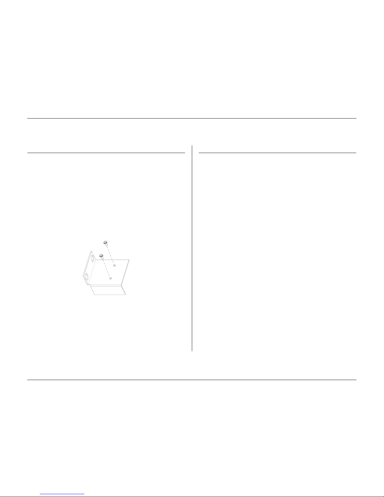
The Divar can be mounted in a 19-inch rack. A rack mounting kit is supplied
with the unit that includes:
• left and right rack mount ears
• four Torx screws with integrated lock washers.
•a Torx screwdriver
Mounting
1.
Remove the four Torx screws (two on each side) located near the front panel on
the right and left side of the housing.
2.
Attach the mounting ears to each side ensuring that the lip is under the unit. Use
the four Torx screws with lock washers and tighten securely.
3.
Install the unit into the rack using the rack manufacturer’s supplied hardware.
When installing the assembly into the rack, be careful not to restrict airflow
around the vent holes located in the side panels or to exceed the recommended
operating temperature.
Camera connections
Connect cameras to the unit using 75-ohm video coaxial cables with BNC
connectors. There are two BNC connectors for each camera. Either connector
can receive a camera's signal. This signal is looped-through (directly connected)
to the other connector, so that you can send the camera's signal to other
equipment. The camera input connectors are auto-terminating, so you do not
need to add a terminator to the output connector if no additional equipment is
connected.
If the camera signal is looped-through to additional equipment, make sure that
the end of the video line is terminated with a 75-ohm termination.
The Divar automatically configures itself as a PAL or NTSC unit. The unit
determines the standard by detecting the signal format of the first connected
camera (lowest camera input number).
Specification
Input signal: Composite video 1Vpp, 75 Ohm
Color standard: PAL/NTSC, auto-detect.
Gain control: Automatic or manual gain control for each video input.
Connector type: BNC looped-through, automatic termination.
Page 33
Hardware setup
Philips Communication, Security & Imaging 4-3
Monitor connections
Connect the unit to the monitors using 75-ohm video coaxial cables with BNC
connectors. The unit provides a 1Vpp CVBS signal.
If the monitor has a loop-through connection and you are not using the loopthrough output, then select the 75-ohm impedance setting on the monitor. If the
monitor's loop-through output is connected to an additional device, the device's
termination is set to 75 ohms and the monitor's termination is set to high
impedance. (Note that this is not necessary on devices with automatic
termination.)
Specifications
Output signal: Composite video 1Vpp, 75 Ohm, Sync. 0.3Vpp ±10%
Resolution: 720 x 576 PAL, 720 X 484 NTSC
Connector type: BNC
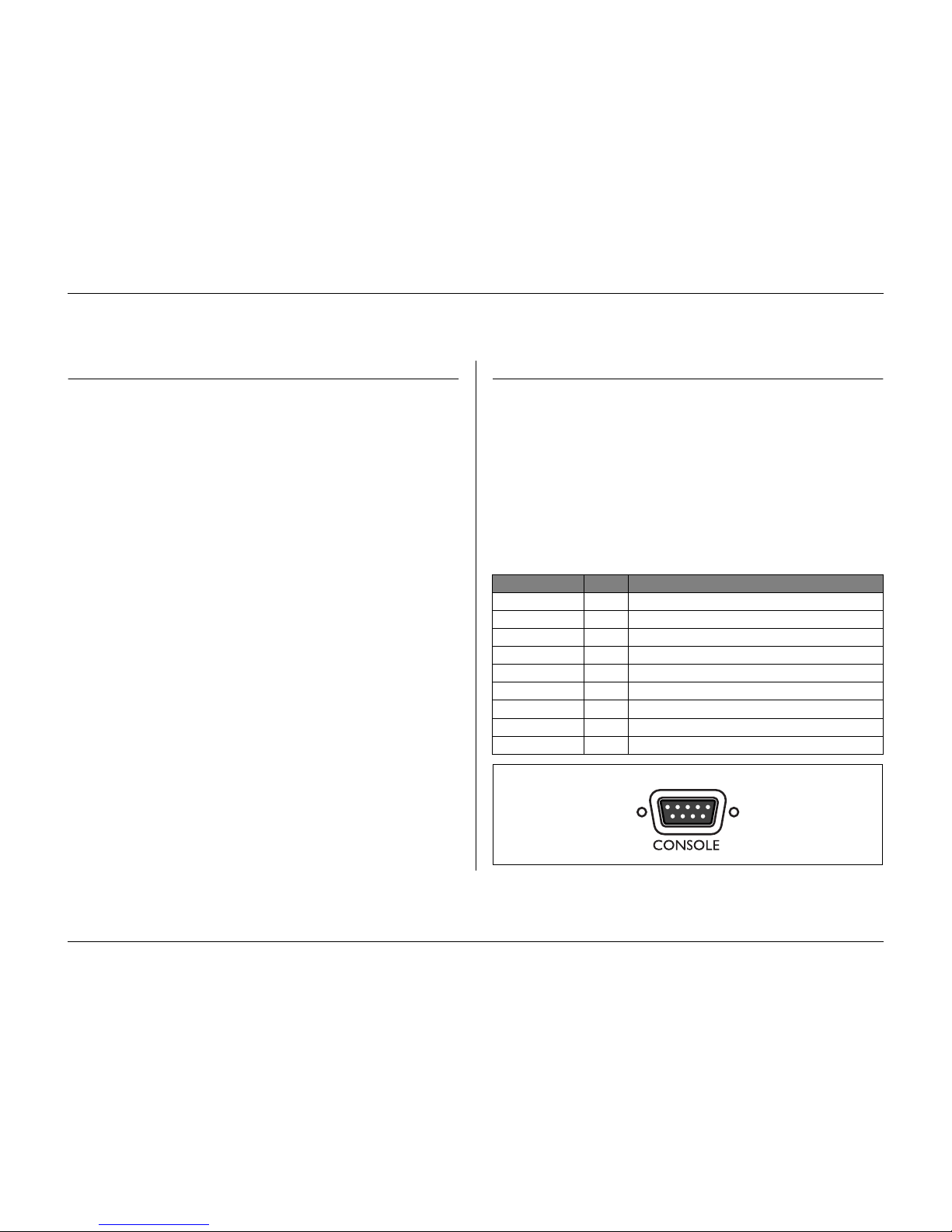
Console port connection
The serial RS232 console port connector is used to connect a PC to the unit for
configuration or service purposes. Use a null-modem cable to connect the serial
port of the PC to the unit. The Baud rate can be selected in the menu system
Specification
Connector type: 9-pole D-type male connector
Maximum input voltage: ±25V
Communicaton protocol: Output signals according EIA/TIA-232-F
RS232 console port socket.
Signal Name: Pin no. Description
DCD_in 1 Carrier detection signal (not used).
RX 2 RS232 receive signal
TX 3 RS232 transmit signal
N/C 4 No Connection
System Ground 5 System Ground
N/C 6 No Connection
RTS 7 RS232 request to send signal
CTS 8 RS232 clear to send signal
N/C 9 No Connection
5
1
6
9
Panel view
Page 34
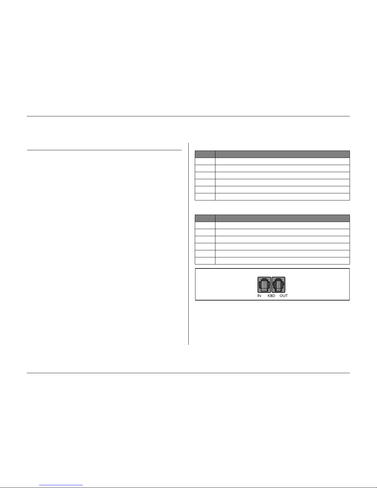
Hardware setup
4-4 Philips Communication, Security & Imaging
Keyboard connections
The keyboard input and output connectors are used to connect an external
keyboard to the unit. Connect the keyboard to the KBD IN connector. Up to 4
external keyboards can be connected when the optional keyboard port expander
(LTC2604) is used.
For short distances (up to 30m), standard 6-core telecom flat cable can be used
to supply power and signal connections for the keyboard.
For distances over 30m, the Keyboard Extension Kit (LTC 8557) must be used.
This kit provides junction boxes, cables and the appropriate power supply for the
external keyboards. The recommended cable type is Belden 9841 or equivalent.
Divar connection
The KBD IN and KBD OUT connectors can also be used to connect several
Divar units to each other. The loop-through connector arrangement allows easy
interconnection of up to 30 Divars. The connection uses RS485-based
communications.
Specifications
Communicaton protocol: RS485
Maximum signal voltage: ± 12V
Power supply: 11 - 12.6V, maximum 400mA
Maximum cable length: 1.5 kilometers
Cable type: black (cross-over) cable (supplied with keyboard)
Termination: 390 Ohm terminator
Keyboard In - RJ11 socket (KBD IN)
Keyboard out - RJ11 socket (KBD OUT)
Pin no. Signal
1 +12 V DC (11V Min to 12.6V Max, 400mA Max)
2 System ground
3 Keyboard plus line
4 Keyboard minus line
5 System ground
6 System ground
Pin no. Signal
1 No Connection
2 System ground
3 Keyboard minus line
4 Keyboard plus line
5 System ground
6 No Connection
61 42
Panel view
Page 35
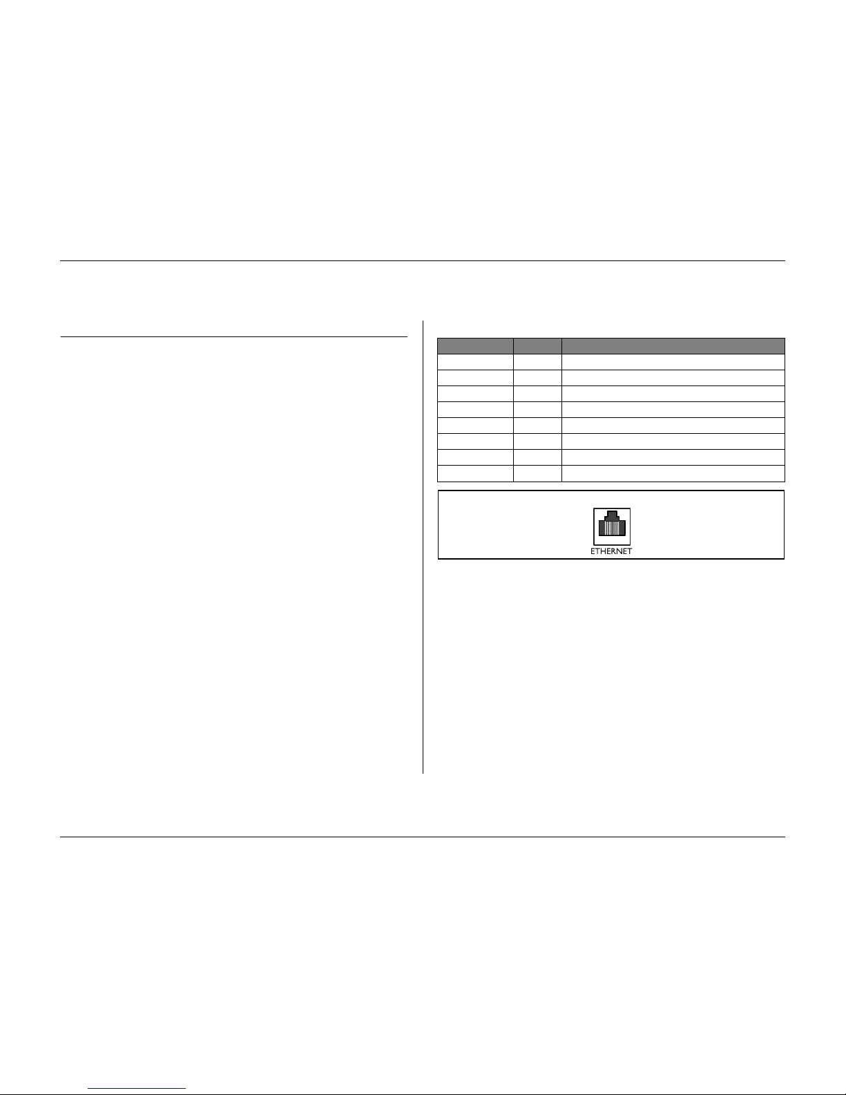
Hardware setup
Philips Communication, Security & Imaging 4-5
Ethernet connection
The standard RJ-45 Ethernet socket is used to connect the unit directly to a PC
or to a network. To connect directly to a network hub, use a straight-through
network cable. To connect directly to a PC, use the supplied cross-over network
cable. Consult with your local IT personnel for the specific type of cable needed.
The cable length from node to node is limited to 100 feet (30.5 meters)
maximum length and 6 feet (1.8 meters) minimum length.
Network configuration
The Divar is delivered with the DHCP function switched on, so IP addresses are
assigned automatically if the network server uses DHCP. (Refer to the
System
settings/Connectivity/Network setup menu.)
Specifications
Connection: 10/100 BaseT, IEEE 802.3
Differential signal voltage: ± 2.8V max, inputs have transient overvoltage protection.
Port details: IEEE 802.3/802.3u - 100Base-TX/10Base-T physical layer.
Auto Negotiation: 10/100, Full / Half Duplex
Cable length: 100 Meters: 100 Ohm unshielded twisted pair cable,
category 3/4/5.
100 Meters: 150 Ohm shielded twisted pair cable.
Impedance: In-built compensation for impedance matching.
Indicators: ACT, 10, 100
LAN - RJ-45 Ethernet socket
Signal Name: Pin no. Description
LAN_TX+ 1 Ethernet transmit line plus
LAN_TX- 2 Ethernet transmit line minus
LAN_RX+ 3 Ethernet Receive line plus
N/C 4 No Connection
N/C 5 No Connection
LAN_RX- 6 Ethernet receive line minus
N/C 7 No Connection
N/C 8 No Connection
81
Panel view
Page 36
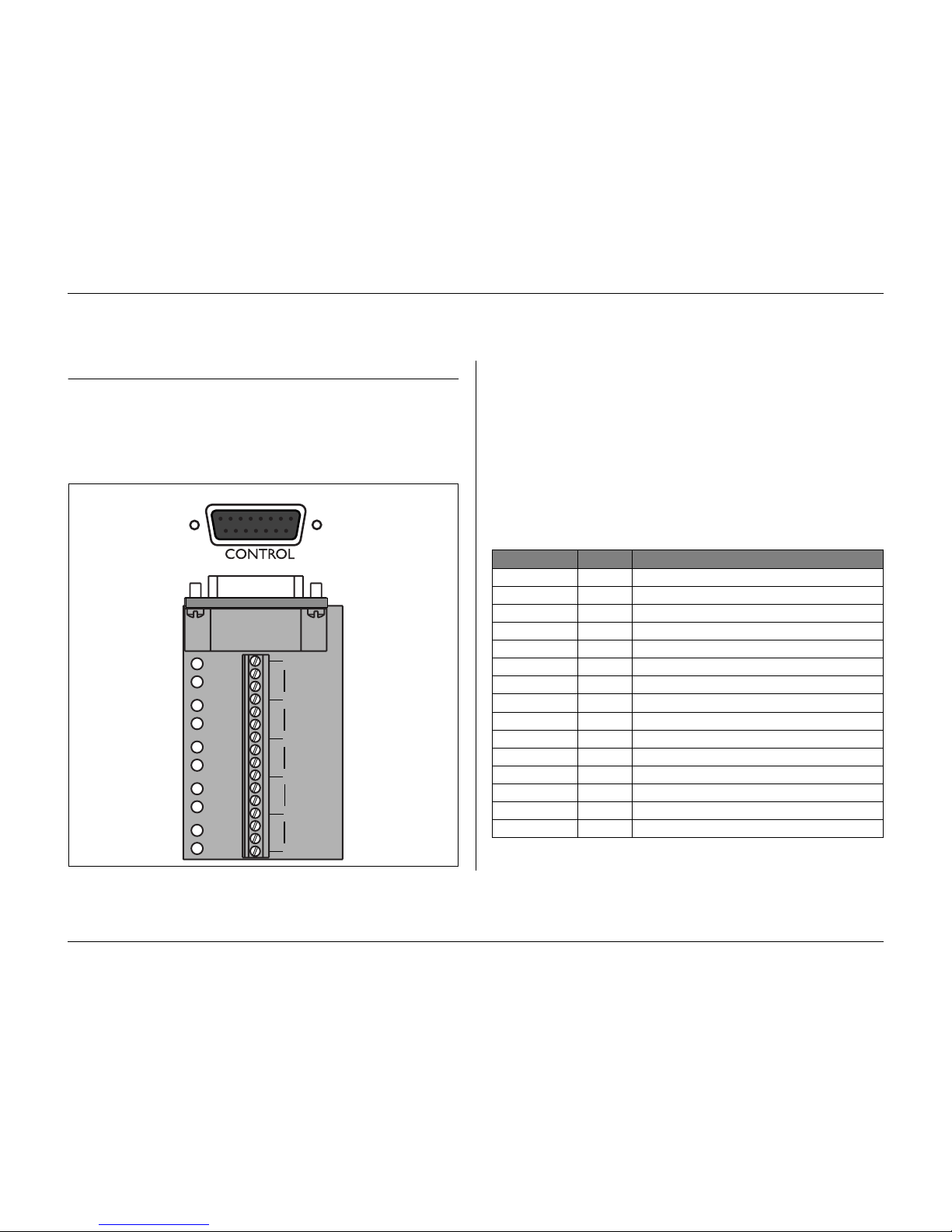
Hardware setup
4-6 Philips Communication, Security & Imaging
Control port
The control port is a bi-phase port for connecting the control units of
controllable cameras. Five bi-phase outputs are provided for dome camera and
pan, tilt and zoom control. The screw terminal connection board supplied with
the unit simplifies all bi-phase connections to the unit.
Specifications
Output impedence: 128 Ohm
Overvoltage protection: ±30V max.
Differential voltage amplitude: 1V min, 2V max. with a characteristic load of 220 Ohms
connected across the differential output
Cable length: 1.5 Kilometers max.
Recommended cable: Belden 8760
Number of loads per output: 4 max.
Control port - 15-pole D-type socket
+
SHIELD
CTRL 1
SHIELD
+
SHIELD
CTRL 2
+
SHIELD
CTRL 3
+
SHIELD
CTRL 4
+
SHIELD
CTRL 5
8
1
9
15
Panel view
Signal name: Pin no. Description
Code 1 - 1 Bi-phase control ch. 1 (minus)
Code 1 + 2 Bi-phase control ch. 1 (plus)
Shield 3 System ground/cable shield.
Code 2 - 4 Bi-phase control ch. 2 (minus)
Code 2 + 5 Bi-phase control ch. 2 (plus)
Shield 6 System ground/cable shield.
Code 3 - 7 Bi-phase control ch. 3 (minus)
Code 3 + 8 Bi-phase control ch. 3 (plus)
Shield 9 System ground/cable shield.
Code 4 - 10 Bi-phase control ch. 4 (minus)
Code 4 + 11 Bi-phase control ch. 4 (plus)
Shield 12 System ground/cable shield.
Code 5 - 13 Bi-phase control ch. 5 (minus)
Code 5 + 14 Bi-phase control ch. 5 (plus)
Shield 15 System ground/cable shield.
Page 37
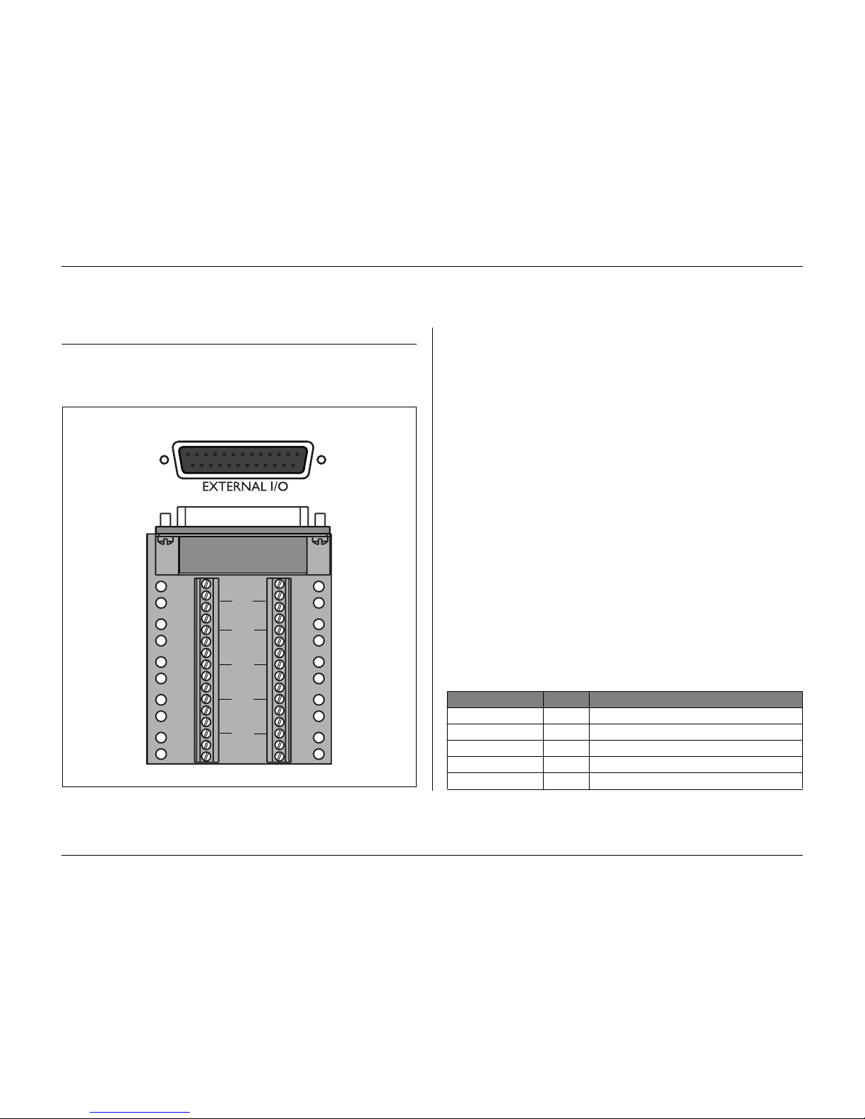
Hardware setup
Philips Communication, Security & Imaging 4-7
External I/O connection
Alarm inputs and outputs are supplied via a 25-pole D-type socket. The screw
terminal input/output connection board supplied with the unit simplifies all
alarm connections to the unit.
Connecting the Inputs
Each (alarm) input line can be switched by a relay contact from devices such as
pressure pads, passive infra-red detectors, smoke detectors and similar devices.
Wire them as either N/O or N/C. You can configure the alarm inputs as N/O or
N/C in the menu system. The default is N/O.
Connecting the Alarm Outputs
The four alarm output relays respond to input alarms and triggers. You can
configure the alarm outputs as N/O or N/C in the menu system. The relays are
active for the duration of the driving event. Connect the application to the alarm
output relays (resistive loads only). Do not exceed 30 Vac, 40Vdc, 500 mA
(continuous) or 10VA on an alarm output relay's contacts. The contacts must
not be used at AC line voltages.
Specifications
Alarm input impedence: Internal pull-up 10K to +5V
Input voltage range: -0.3V min to 30V max
Input voltage treshold: Low voltage 0.8V max
High voltage 2.4V min
Switching current (resistive): 500mA max
Carrying power: 10VA max
Switching voltage (resistive): 30 Vac / 40 Vdc max
External I/O - 25-pole D-type socket
1A
1B
2A
2B
R
E
L
A
Y
3A
3B
4A
4B
GND
1
2
GND
9
10
3
4
GND
11
12
5
6
GND
13
14
7
8
15
16
IN
IN
IN
IN
13
1
14
25
Panel view
Signal name: Pin no. Description
Alarm_in_1 1 Alarm input 1
Alarm_in_2 2 Alarm input 2
Alarm_in_3 3 Alarm input 3
Alarm_in_4 4 Alarm input 4
Alarm_in_5 5 Alarm input 5
Page 38
Hardware setup
4-8 Philips Communication, Security & Imaging
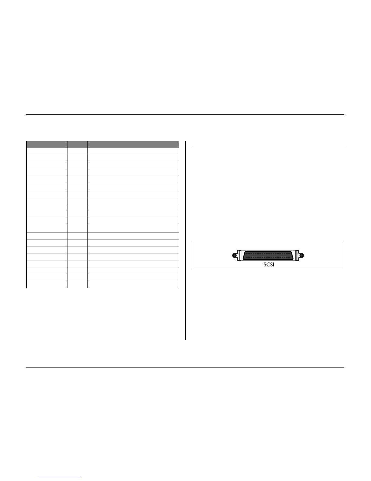
SCSI connection
The unit provides a 50-pin high density SCSI-2 port for connection of an
external storage system, for example, a LP (DVAD) or a RAID (DVAS) storage
array. To use this feature, connect the drive's SCSI cable to the SCSI-2 connector
on the rear panel.
Specification
Connector type: 50-pin narrow SCSI connector for external SCSI device
Bus format: Narrow (8 Bits) single-ended
Max. number of SCSI devices: 7
Max. transfer rate: 20 Mbytes per second
Total cable length: Fast-20
1 to 4 SCSI devices 3m
5 to 7 SCSI devices 1.5m
Alarm_in_6 6 Alarm input 6
Alarm_in_7 7 Alarm input 7
Alarm_in_8 8 Alarm input 8
Alarm_in_9 9 Alarm input 9
Alarm_in_10 10 Alarm input 10
Alarm_in_11 11 Alarm input 11
Alarm_in_12 12 Alarm input 12
Alarm_in_13 13 Alarm input 13
Alarm_in_14 14 Alarm input 14
Alarm_in_15 15 Alarm input 15
Alarm_in_16 16 Alarm input 16
Relay1_A 17 Relay 1 output pole 1
Relay1_B 18 Relay 1 output pole 2
Relay2_A 19 Relay 2 output pole 1
Relay2_B 20 Relay 2 output pole 2
Relay3_A 21 Relay 3 output pole 1
Relay3_B 22 Relay 3 output pole 2
Relay4_A 23 Relay 4 output pole 1
Relay4_B 24 Relay 4 output pole 2
System Ground 25 Chassis Ground
Signal name: Pin no. Description
25
1
26
50
Panel view
Page 39
Hardware setup
Philips Communication, Security & Imaging 4-9
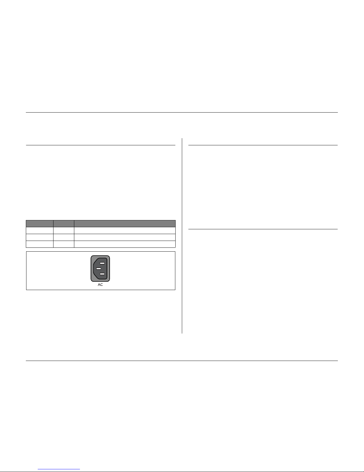
Power Supply
Power is supplied to the unit via the IEC-style socket. The unit has no on/off
switch for security reasons. This means that the unit is always powered as long as
the power cable is connected from the unit to a live power socket.
Specifications:
Input Voltage: 100 - 240 Vac ±10%
Current: 0.7A - 0.3A
Input Frequency: 50/60 Hz
Power supply socket
Te s t i n g
In Live mode, select full-screen display for each camera and check the picture
quality. If the quality is poor, check:
•The BNC connections.
• Loop-through terminations.
• Video levels of incoming signals and the possibility of ground loops.
Record for at least three minutes at the highest recording speed Then play back
the recording, selecting each camera for full-screen display in turn. Check the
playback picture quality. Check to see whether the programmed quality setting is
adequate.
Maintenance
Maintenance of this unit is limited to external cleaning and inspection. Refer all
servicing to qualified personnel.
WARNING!
Do not open the top cover or attempt to service the unit as this may expose you
to dangerous voltages and other hazards. Opening the unit will void the
warranty!
Signal name: Pin no. Description
LIVE 1 AC live
NEUTRAL 2 AC neutral
PE 3 Protective Earth
N
L
E
Panel view
Page 40

Hardware setup
4-10 Philips Communication, Security & Imaging
Page 41

Philips Communication, Security & Imaging 5-1
CHAPTER 5
Menu system
You access all the parameters used to set up the unit via the menu system. The
large number of parameters available gives you the opportunity to program an
extensive functionality.
There are two ways of accessing the menu system, via the keys on the front of the
unit itself or via the PC-based Configuration Tool application. Using the keys on
the unit has the advantage of not requiring a PC and is the recommended
method if you are using the unit in a stand-alone configuration. If you do have a
PC connected to the unit or the unit is used in a network environment, then the
Configuration Tool offers a more convenient way of accessing and using the
menu.
In both cases the parameters available are the same. Slight differences in
navigation and selection are only due to the differences between the keys on the
unit and the keyboard and mouse interface of the PC. The menu structure is the
same in both cases.
This chapter explains how to use the keys on the unit to access the menus. It also
documents the full structure of the menu system. To find out how to use the PCbased Configuration Tool refer to Chapter 6.
Page 42
Menu system
5-2 Philips Communication, Security & Imaging
Overview of the menu system
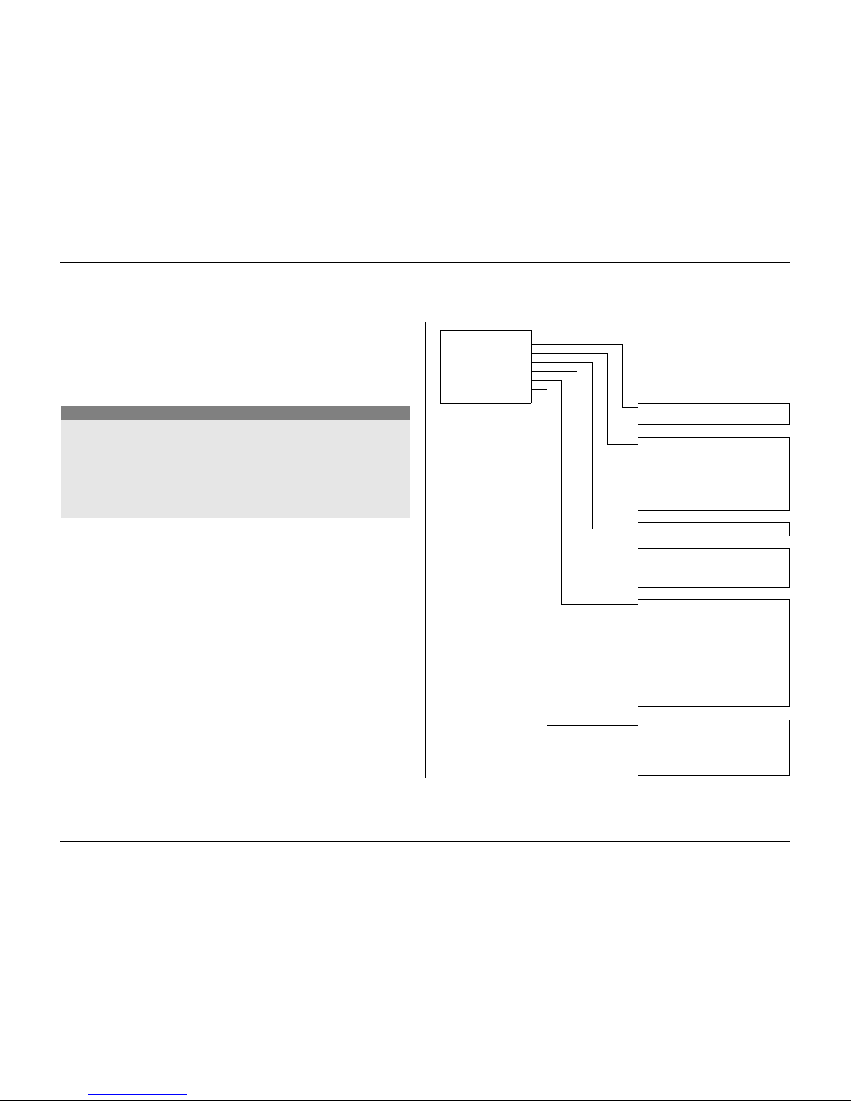
The main menu consists of six menu groups:
History.
The
Histor y
menu allows you to trace all events that have occurred on
the unit.
Disk manager.
The
Disk Manager
menu provides information and functions
that relate to the maintenance of the storage system including internal and
external hard disks.
Time/Date.
The
Time/Date
menu is used to set the actual reference time and
date for the unit and the format that is used to display them.
View settings.
The
View Settings
menu is used to program how the individual
cameras are displayed on the monitors.
System settings.
The
System Settings
menu is where most of the static
parameters for the unit are set.
Profiles.
The
Profiles
menu is used to set up and store the dynamic
characteristics of the unit.
Setting the dynamic characteristics
The settings in the
Profiles
menu provide the opportunity to tap the powerful
functionality of the unit. By spending some time in planning and setting up the
six profiles available, you can provide efficient use of resources while maintaining
effective cover for most types of working situations.
Profiles are usually based on a calendar, switching on and off at a particular date
or time (for example, weekends or night). Profiles can also be switched by an
input signal based on an external switch or armed alarm system.
A profile determines how a unit behaves when that profile is active. Unit
behavior includes how events are handled. It also defines recording rates both
under normal conditions and in response to input and motion events.
Unit behavior can be set up differently for each of the six profiles. Profiles can be
named and copied to facilitate their setup and management.
Accessing the menu from the unit
To open the menu:
1.
Press the ALT key to enter the alternate function mode.
> The ALT indicator lights.
2.
Press the menu key.
> The main menu appears full-screen on monitor A.
Navigating
• Use the arrow keys to move through a menu or list.
• Use the select key to select a submenu or item.
• Use the escape key to go back.
Access to some menu items can be password protected.
Page 43
Menu system
Philips Communication, Security & Imaging 5-3
M
AIN MENU
The main menu gives access to six major menu groups. Each of these groups has
a submenu tree where the values and functions can be selected.
•Set
Advanced Menus
to
Ye s
to see all items; set to No for standard
features only.
MAIN MENU
HISTORY >
DISK MANAGER >
TIME / DATE >
VIEW SETTINGS >
SYSTEM SETTINGS >
PROFILES >
ADVANCED MENUS NO
Main menu
History
Disk manager
Time / Date
View settings
System settings
Profiles
Advanced menus
History
View history list
Disk manager
Status overview
Protected recordings
Authenticity check*
Stop recording
Storage setup*
Delete video
Erase disk
Time / Date
View settings
Camera setup
Sequences
Configure monitors
System settings
Language
Quick install
Record setup
Playback setup*
Event setup
History log setup
Local passwords
Connectivity*
Licenses*
Input and output contacts*
Factory defaults
Profiles
Currently active
Calendar setup
Profile override
Profile manager
System behavior
* advanced items
Page 44
Menu system
5-4 Philips Communication, Security & Imaging
H
ISTORY
>
The
Histor y
menu provides a list of all events that have occurred. This list can
be filtered to show only those events you wish to see.
>> History Filter
• Fill in the date/time values to restrict the period for viewing events.
•Select
No
for those events that you do not wish to see.
>> History List
• The latest event is shown first.
• Use the right/left arrow keys to move through a long history list.
• If a date or time has been changed, the original values are also displayed.
• Alarm, motion and video loss events are stored for a maximum of one
month.
D
ISK MANAGER
>
The
Disk Manager
menu gives access to information on the internal hard disk(s)
and any external disks connected. The status of the recorded video and associated
data is also accessed via this menu. Access to some menus can be password
protected.
>> Status Overview
•
Disk Capacity
shows the total space available in Gigabytes.
•
Used Space
shows the total space used by all video recordings including
protected recordings.
•
Protected Recordings Usage
shows the space used by protected
recordings that cannot be overwritten.
•The displayed
Recording Time Left
value depends on the recording
options that are set, and alarm and motion frequency. The estimated
recording time shown depends on the available storage capacity and
recording setup.
MAIN MENU
HISTORY
VIEW HISTORY LIST >
BEGIN TIME 2002-03-14 13:00
END TIME 2002-06-19 20:23
SHOW
ALARMS YES
MOTIONS YES
NETWORK CONNECTIVITY YES
ERRORS YES
EARLIEST TIME 2002-03-14 13:00
LATEST TIME 2002-06-19 20:23
MAIN MENU
DISK MANAGER
STATUS OVERVIEW >
PROTECTED RECORDINGS >
AUTHENTICITY CHECK >
STOP RECORDING >
STORAGE SETUP >
DELETE VIDEO >
ERASE DISK >
Page 45
Menu system
Philips Communication, Security & Imaging 5-5
>> Protected Recordings
• Move to a protected recording in the list and press the select key to
play it back.
• Press the escape key to stop playback and return to the list.
• To remove the protection of a recording, move to it in the list and press
F2. You must fill in a password (if configured) and confirm before the
recording is unprotected.
>> Authenticity Check
• This check verifies that video images and associated data have not been
modified.
• Select the period within which the authenticity check runs. The default
values are the same as the earliest and latest available recording times.
• Press the escape key to cancel the check.
• During the check all other front panel keys are disabled.
•If the result is
Not OK
, the date and time of the tampered video is
displayed.
>> Stop recording
• Set the period for which you wish to temporarily stop recording.
• The maximum period is one hour.
• The duration counts down to zero.
• Alarms are not recorded when recording is interrupted.
• Interruption of recordings is always logged in the history list.
• Recording starts automatically when interrupt period has elapsed.
>> Storage setup
•
Storage Setup
gives an overview of internal and external storage. The
total disk space available is shown in Gigabytes.
• Any new disks found are disabled by default.
• Select the storage location you wish to enable or disable. All recorded
video is lost if you change a disk configuration. If you choose
Ye s
to
continue, all video is erased.
•Select
Storage Status
for an overview of the status of all internal and
external disks.
>>> Storage status
•OK if everything is all right.
•
Fail
if for some reason the disk is not working properly.
•
Fail - reconfigure storage
if the disk is not part of the disk set or is
empty.
•
SCSI mismatch: change ID to X
where X is the expected SCSI ID
and the SCSI ID needs to be changed.
•
Not found
if the disk is not connected
•
Unused
if a valid disk is found which is not used (disabled).
>> Delete Video
• Delete recorded video by filling in an end date and time, and selecting
delete video.
• All non-protected recordings made before the specified date and time are
deleted. You must confirm the deletion.
• Protected recordings are not deleted.
>> Erase Disk
• Deletes all recorded video on the disk.
• You must confirm the deletion.
Page 46
Menu system
5-6 Philips Communication, Security & Imaging
T
IME/DATE
>
• Fill in the actual time and date.
• Select either a 12-hour or a 24-hour clock format.
• Select from three date formats which show either the month (MM), the
day (DD) or the year (YYYY) first.
>> Synchronize
•Use the
Synchronize
function to set the time of the unit from the time of
the network. (Synchronize only works if the Divar time is within 7½
minutes of the server time.) Fill in the IP address of the network time
server.
• The time and date of all other connected units are automatically
synchronized every hour from the time and date of the unit with DVR
ID 1.
V
IEW SETTINGS
>
The
View Settings
menu allows you to set up the display of the individual
cameras. You can also set the sequence in which the cameras are displayed and
the duration. Use the
Configure Monitors
submenu to set up the monitor
displays.
>> Camera setup
Use the
Camera Setup
menu to access the submenus for setting the camera
names, for locking cameras and for controlling cameras.
>>> Camera name
• Select a camera by pressing a camera key on the unit. The number
of the camera is the number of the connector at the rear of the unit
to which it is connected.
• Enter a name for the selected camera. The name can be up to 16
characters long.
>>> Camera lock-out
• Locked cameras are not visible during normal use.
• Place a check mark under the number of the camera you wish to
lock or press a camera key on the unit to switch the lock on or off.
• Select the
Set Password
submenu and fill in a 4-digit password to
restrict access to the camera lock-out menu.
MAIN MENU
TIME/DATE
TIME FORMAT 24 HOUR
TIME 14:00:17
DATE FORMAT YYYY-MM-DD
DATE 2002-06-19
SYNCHRONIZE >
MAIN MENU
VIEW SETTINGS
CAMERA SETUP >
SEQUENCES >
CONFIGURE MONITORS >
Page 47
Menu system
Philips Communication, Security & Imaging 5-7
>>> Camera control
• Set the
Auto Camera Contrast
to On to let the system
automatically adjust the contrast for each camera.
• If you set the
Auto Camera Contrast
to
Off
, you can access the
Adjust Contrast
submenu.
Adjust contrast
• Select a camera in the menu or press a camera key on the unit. The
selected camera image appears.
• Vary the manual gain value between -100 and +100 to adjust the
contrast.
• To set the default value (0), press the F1 key.
>> Camera controllable
• A check mark under a camera number indicates that it can be controlled
remotely by the Control Center application.
• Press a camera key on the unit to make a camera controllable or not.
• By default all cameras are controllable.
>> Sequences
The sequence in which cameras are displayed on monitor A and monitor B is set
in the full screen list menu.
• Set the length of time each image remains on the screen by filling in the
dwell time value for each monitor.
• Dwell time can vary from 1 to 60 seconds. The default value is 5 seconds.
>>> List Full screen monitor A
• The sequence list shows the order in which the camera images are
displayed in full screen mode.
• Use the arrow keys to select a position in the list. Press a camera key
on the unit to enter a camera number in the list.
• Press F2 to clear the rest of the list.
• Press F1 to restore all defaults. Connected cameras are then listed in
ascending order.
>>> List Full screen monitor B
• The sequence list shows the order in which the camera images are
displayed in full screen mode.
• Use the arrow keys to select a position in the list. Press a camera key
on the unit to enter a camera number in the list.
• Press F2 to clear the rest of the list.
• Press F1 to restore all defaults. Connected cameras are then listed in
ascending order.
>> Configure Monitors
• To view camera names, and time and date on a monitor set these items to
On
.
• Select the position for the text (top or bottom and fine position +11/-11).
Select text intensity. Select the border intensity of the cameos from four
values.
• To automatically close the menu when an alarm or event occurs, set the
Exit Menu on Alarms
item to
Ye s
.
• The menu is closed after five minutes if you set the
Menu Time-out
to
On
.
Page 48
Menu system
5-8 Philips Communication, Security & Imaging
>>> Multiscreen modes
• Pressing the multiscreen key on the unit cycles through all enabled
multiple view modes.
• Enable only those views you wish to see when you use the
multiscreen key.
• The multiscreen modes that are available depend on the number of
cameras connected and the Divar model.
S
YSTEM SETTINGS
>
Use the System Settings menu to get access to those items that are used to
configure the system.
• Select the language for the menu from the list.
•Select
Quick Install
to quickly set up the system. The quick install menu
is described in Chapter 2.
•If you select
Factory Defaults
, all settings in the menu system are reset to
their default value.
>> Recording Setup
• The continuous mode overwrites older recordings when the disk is full.
You can set an overwrite protection period of up to 15 weeks for the latest
recordings.
• The linear mode first gives a warning and then stops recording when the
disk is full. Older recordings must be manually deleted.
•Set the
Pre-event time
so that recording begins before an alarm is
activated. The maximum is 30 seconds.
MAIN MENU
SYSTEM SETTINGS
LANGUAGE ENGLISH
QUICK INSTALL >
RECORDING SETUP >
PLAYBACK SETUP >
EVENT SETUP >
HISTORY LOG SETUP >
LOCAL PASSWORDS >
CONNECTIVITY >
LICENSES >
INPUT AND OUTPUT CONTACTS >
FACTORY DEFAULTS
Page 49
Menu system
Philips Communication, Security & Imaging 5-9
>>> Disk Full Alarm Setup
• Set the percentage of used disk space at which the disk-full warning
message is displayed.
• Set the time in minutes before the disk is full at which a disk-full
alarm is generated.
• Select the number of the output relay that is activated when a diskfull alarm is generated.
• Enable the beeper to activate it when a disk-full alarm is generated.
>> Playback Setup
Use the
Playback Setup
list to block the playback of recordings from particular
cameras after a specified period of time.
• Choose from No Block, 1 to 7 days, 14 days, 21 days, 28 days or 31 days.
When the specified time has elapsed, the recordings of that camera from
before that time cannot be played back.
>> Event Setup
Use the
Event Setup
menu to specify the display behavior for an input, detected
motion or video loss.
•Set the
Alarm Dwell Time
to select the period during which the output
relay and the beeper remain active after activation.
•Set the
Tr i gg e r D we l l T im e
to select the period during which the
triggered view mode is displayed after activation.
•The value
Foll ows
activates the beeper and relay or view, only as long as
the event is present.
>>> Input Setup
• To restore the default input settings select the
Clear Input Settings
item.
• Select the
Display Monitor
submenu to choose the view mode and
cameras to be displayed when an input is activated.
• Select the number of the output relay to be activated when any
alarm input is activated.
• Enable the beeper to activate it when an alarm input is activated.
Display mon A
• Select the input number (1 to 16) for which you wish to set the view
mode.
• If you have controllable cameras, set a camera number and a preposition number (1 to 99). The specified camera goes to this
position when the numbered input is activated.
• Select a view mode. Only view modes that are enabled can be
selected.
• If you have selected the full-screen or quad view mode, select the
cameras to be displayed.
Display mon B
• Select the input number (1 to 16) for which you wish to set the view
mode.
• If you have controllable cameras, set a camera number and a preposition number (1 to 99). The specified camera goes to this
position when the numbered input is activated.
• Select up to four cameras to be displayed in sequence.
Page 50

Menu system
5-10 Philips Communication, Security & Imaging
>>> Motion Setup
• To restore the default motion settings select the
Clear Motion
Settings
item.
• Select the
Display Monitor
submenu to set up the view mode and
cameras to be activated on the monitor for each motion event. The
Motion Area
submenu sets the area and sensitivity for each camera.
• Select the number of the output relay that is activated when motion
is detected.
• Enable the beeper to activate it when any motion is detected.
Display mon A
• Select the camera number that generates the motion event.
• If you have controllable cameras, set a camera number and a preposition number (1 to 99). The specified camera goes to this
position when motion is detected by the selected camera (not
necessarily the controllable camera).
• Select a view mode. Only view modes that are enabled can be
selected.
• If you have selected the full-screen or quad view mode, select the
cameras to be displayed.
Display mon B
• Select the camera number that generates the motion event.
• If you have controllable cameras, set a camera number and a preposition number (1 to 99). The specified camera goes to this
position when motion is detected by the selected camera (not
necessarily the controllable camera).
• Select up to four cameras to be displayed in sequence.
Motion area
• Select a camera number.
•The
motion indicator
shows the maximum level of camera motion
that has been detected for the defined area. Press F2 to clear it if you
want to re-test the level of motion detection.
• Use the arrow keys to adjust the
Trigger level
slider to just below
the indicated motion level.
• A motion detection signal is generated when the level of motion
reaches the trigger level set.
Edit area
•Select
Motion Area
to define the picture area where motion is
detected.
• Use the arrow keys to move around the grid. Press F1 to insert a
motion detection area and use the arrow keys to enlarge it. Press F1
again to save the area. Press the escape key to cancel and return to
grid square selection.
• Press the select key to leave the grid. F2 clears all motion detection
areas.
>>> Video loss Setup
• Select the monitor on which the camera with the video loss is
displayed.
• Select the number of the output relay that is activated when video
loss occurs.
• Enable the beeper to activate it when any video loss occurs.
>> History Log Setup
•Select
Ye s
for those events that you want to log in the history file.
• The entire history list is erased if you select the
Clear History
item.
• Date/time changes of stored video are always logged and cannot be
disabled or cleared.
Page 51
Menu system
Philips Communication, Security & Imaging 5-11
>> Local Passwords
• Set or change the password that allows access to playback functions.
• Set or change the password that allows access to the configuration
functions.
• Use the camera keys (1 to 9) on the front of the unit to enter a four-digit
password in the dialog box that appears.
• Enter the same password again to have it verified.
• Press F2 to remove password protection.
>> Connectivity
The
Connectivity
menu gives access to settings that control the behavior of the
unit with respect to all external devices or a network. It also gives access to
settings for connecting multiple units to each other and for connecting
computers via the communications port.
>>> Keyboard access restrictions
• Four external keyboards can be connected to the unit.
• Allow these keyboards to control monitor A only, monitor B only,
both or neither.
>>> Network setup
•Set DHCP to
Ye s
to have IP address, subnet mask and default
gateway assigned automatically by the network server. The actual
values are displayed.
• Enter a Divar name to be used in the network.
• Fill in the IP, subnet mask and default gateway addresses when
DHCP is set to
No
. The MAC address is read only.
• Restrict the network bandwidth by entering an Mbps between 0 and
100 for the bandwidth limit.
>>> Network access
• Access to the unit via the network can be set for up to six different
users.
• Restrict access to the unit by listing an IP address range. The range
you use will normally depend on your network setup.
• Select a user number to set up the configuration for that remote
user. The administrator is user 1 and is identified as
ADMINISTRATOR.
IP Range
• Eight IP ranges can be entered to allow access.
• Enter the same begin and end address to specify a single IP address.
Enter different begin and end addresses to specify an IP address
range.
• Use the up/down arrow keys to move to an IP entry. Press the select
key to edit the entries. Press F1 to set the default values
(000.000.000.000 to 255.255.255.255).
List of Users
• Enter a name, up to 16-characters long, for each user. Enter a
password up to 12-digits long.
•Set
User Rights
to
Live
to restrict viewing rights to live video only.
• Select the cameras in the
Camera Lock Out
submenu that are not
accessible for the user.
• Set the camera sequence list and dwell time (from 3 to 59 seconds)
for the remote viewer. All connected cameras are listed by default.
•Set
Camera Control
to allow control of controllable cameras
remotely.
Page 52
Menu system
5-12 Philips Communication, Security & Imaging
>>> Expand system
• When you have multiple units linked, give each unit a unique
identification number (from 1 to 30).
• Enter a first camera number (from 1 to 999) to offset the camera
numbers for the different Divars.
• Only default camera identification numbers (Camera 1, Camera 2,
etc.) are offset.
>>> COM port
• The COM port is an RS232 serial port used mainly for connecting
a PC to the unit.
• Most parameters are fixed. Select the appropriate baud rate.
>> Licenses
• The license key supplied with the unit for a single user is shown first.
• Fill-in the key of any additional licenses you purchase exactly as supplied.
• The MAC address and a description of the installed licenses are shown at
the bottom of the menu-screen.
>> Input and output contacts
• The contacts of the input and output relays default to normally
open (N/O).
• Place a check mark in the box under a specific relay to set its contacts to
normally closed (N/C).
• Press a camera key to place or remove a check mark.
P
ROFILES
>
Six different profiles can be stored. These profiles can be activated by an input
switch or by a date or time. The profiles contain configuration settings for
recording data, handling events and restricting access. You can define a calendar
that automatically selects profiles. These profiles can be configured for day,
night, weekend or holidays for example.
>> Calendar setup
• The use of profiles is defined in a calendar that covers one week. This
calendar is then repeated for subsequent weeks.
• A profile is specified at intervals of 15 minutes for each day of the week.
• You can program exception days to change profiles for special days and
holidays.
>>> Calendar edit
•The
Calendar Edit
menu shows the profile identification numbers
used in a 24-hour period (0 to 23). Each hour is divided into four
15-minute periods.
• To see the other days of the week use the left /right arrow keys.
• Select the
Add Schedule
item to edit the calendar.
MAIN MENU
PROFILES
CURRENTLY ACTIVE 1
CALENDAR SETUP >
PROFILE OVERRIDE >
PROFILE MANAGER >
SYSTEM BEHAVIOR >
Page 53
Menu system
Philips Communication, Security & Imaging 5-13
Add schedule
• Select the profile name, the begin and end times, and the days on
which you want the profile to be active.
• Only five profiles changes can occur in any one day.
• Select a number from 0 to 23 for the hour. Select between 0, 15, 30
or 45 for the minutes.
• If the begin time is later than the end time, then the profile is active
from the end time until the begin time on the next day.
>>> Exception days
• Up to 32 exception days can be set that override the calendar list.
• Use the up/down keys to move to an exception entry and press the
select key to start editing. Enter the start date/time, the duration
and the profile name.
• Press the F2 key to empty an entry.
>> Profile override
• Select a different profile to manually override the active profile for a
temporary period.
• Set the duration for which you wish to override the active profile. The
maximum is 24 hours. If set to
Always
, the calendar is disabled
completely. If set to zero, the override function is disabled.
>> Profile manager
•The
Profile Manager
lists the scheduled and active profiles.
•The
Profile Override Inputs
submenu sets up the inputs to switch
profiles.
•The
Profiles Titles
submenu assigns names to the six different profiles.
>>> Profile override inputs
• Six inputs can be set up to select a profile.
• The active profile defined by the calendar and exception day
schedule is overridden by the input selection as long as the input is
active.
• Inputs used for other purposes cannot be used to select a profile.
• An entry is set to empty by selecting it and pressing F2.
>>> Profile titles
• Select a profile. Enter up to 12 characters to give a meaningful name
to the profile.
>> System behavior
•Use the
System Behavior
menu to configure the event handling, the
recording setup and the access restrictions for each of the six profiles.
• Profile settings can be copied from one profile to another in the
Copy
System Behavior
submenu.
>>> Event handling
• Select the profile for which you wish to configure the event
handling.
• Move to the line that you wish to change. Press the camera keys to
select an input or camera. Press the select key to enable or disable
the selection. A check mark means enabled.
• Enabled selections act as triggers. If alarm is checked, the selection
acts as an alarm.
Page 54
Menu system
5-14 Philips Communication, Security & Imaging
>>> Output handling
• Select the profile for which you wish to configure the output
handling.
• Select the number of the output relays to be activated when an
enabled event in the selected profile is activated.
• Enable the beeper to activate it when an enabled event in the
selected profile is activated.
>>> Recording setup
• Recording behavior for each of the six profiles is specified in three
submenus. The
Normal
submenu is for a normal situation without
alarms or motion events. The
Input
submenu is for input changes.
The
Motion
submenu is for motion events.
• The list gives an overview of inputs and motions that are used in any
of the profiles. A check mark means used.
Normal
• Select the profile. The
Unallocated IPS
item shows the IPS
capacity remaining.
• A total of 60 images per second (IPS) can be recorded for NTSC; 50
IPS for PAL. A minimum of 1 IPS is always allocated per camera for
pre-alarm recording and network viewing.
• Set the recording rates and quality levels for each camera. Quality is
standard, medium or high.
• IPS rates for PAL range from Never, 0, 1/10 (one image every 10
seconds), up to 25 IPS.
• IPS rates for NTSC range from Never, 0, 1/10 (one image every 10
seconds), up to 30 IPS.
• Set the recording speed to NEVER to not record a camera at all. No
pre-alarm recording is done and the camera cannot be viewed over
the network.
Input
• Each input, when activated, can change the normal recording
behavior of up to four cameras for a maximum of 120 seconds.
• Select the profile. Select the input number.
• Select the cameras whose recording behavior should change. Set the
recording rates and quality levels for each camera. Set camera name
to
None
to use less than four cameras.
• To free IPS bandwidth, the recording rate of cameras not in alarm is
limited to the IPS number displayed.
Motion
• Each motion input, when activated, can change the normal
recording behavior of up to four cameras for a maximum of 120
seconds.
• Select the profile. Select the motion camera number.
• Select the cameras whose recording behavior should change. Set the
recording rates and quality levels for each camera. Set camera name
to
None
to use less than four cameras.
• To free IPS bandwidth, the recording rate of cameras not in alarm is
limited to the IPS number displayed.
>>> Access restrictions
• Remote access restrictions can be set for each of the six profiles.
Remote user 1, the administrator, always has access.
• Select the profile. Select if remote playback can be enabled or not
for remote users.
• Select which remote users have access and which are blocked.
>>> Copy system behavior
• To copy the settings of one profile to another, enter the number of
the source profile, enter the number of the destination profile and
select the
Copy Now
item.
Page 55

Philips Communication, Security & Imaging 6-1
CHAPTER 6
Using the Configuration
Tool
The Configuration Tool is a software application that makes the installation and
configuration of a unit faster and easier. The Configuration Tool runs on a PC
that is connected to the Divar either directly via an RS232 serial connection or
via an Ethernet network connection.
Although all settings can also be configured with the on-screen display menu of
the Divar itself, the Configuration Tool offers a very user-friendly alternative. It
also allows configuration settings to be saved on the PC hard disk. These can be
restored later and used to configure other units.
Page 56
Using the Configuration Tool
6-2 Philips Communication, Security & Imaging
Getting started
To use the Configuration Tool to change settings, the unit must be physically
connected to a PC via the RS232 Console Port or via a network connection. The
Configuration Tool application must be installed on the PC.
System requirements
Operating platform: A PC or compatible running Windows 95, Windows 98,
Windows Millennium, Windows NT 4.0 (SP4), Windows
2000 or Windows XP.
For the Configuration Tool application, the
minimum
PC requirements are:
•
Processor: 200 MHz Pentium with MMX (or equivalent)
•
RAM memory: 32 MB (depends on operating system)
•
Hard disk space: 15 MB free
•
Video system: 800x600 with 16-bit color
•
Connectivity: A free RS232 port or a 10/100-BaseT network interface
Installing the Configuration Tool
The Configuration Tool is automatically installed on the PC when you install
the Control Center application. To install separately:
1.
Insert the CD-ROM into the CD-ROM drive on your PC.
> The installation program star ts automatically.
2.
If installation does not start automatically, locate the Setup.exe file on the CD and
double click it.
3.
Follow the instructions on the screen and select to install the Configuration Tool
when asked to complete the installation.
Starting the Configuration Tool
Starting the Configuration Tool depends on how you are connected to the unit:
• via a serial RS232 connection,
• via a network, or
•offline
Serial connection
If your PC is connected directly to the unit via the serial RS232 connection,
double click the Configuration Tool icon on your desktop window to start the
program. Select the
Serial connection
entry from the DVR list.
Network connection
To start the Configuration Tool without using the Control Center, double click
the Configuration Tool icon on your desktop window to start the program.
Alternatively, select the Divar Configuration Tool program via the Start button
on the task bar and the Programs menu item. Follow the login procedure.
To start the Configuration Tool via the Control Center, click the
Config
button
in the Control Center window. You must first be logged into the Control Center
as an administrator to open the Configuration Tool in this way.
Offline configuration
If you choose to log in with an offline configuration, you should select the
model, the video standard and the cameras that are connected.
Page 57
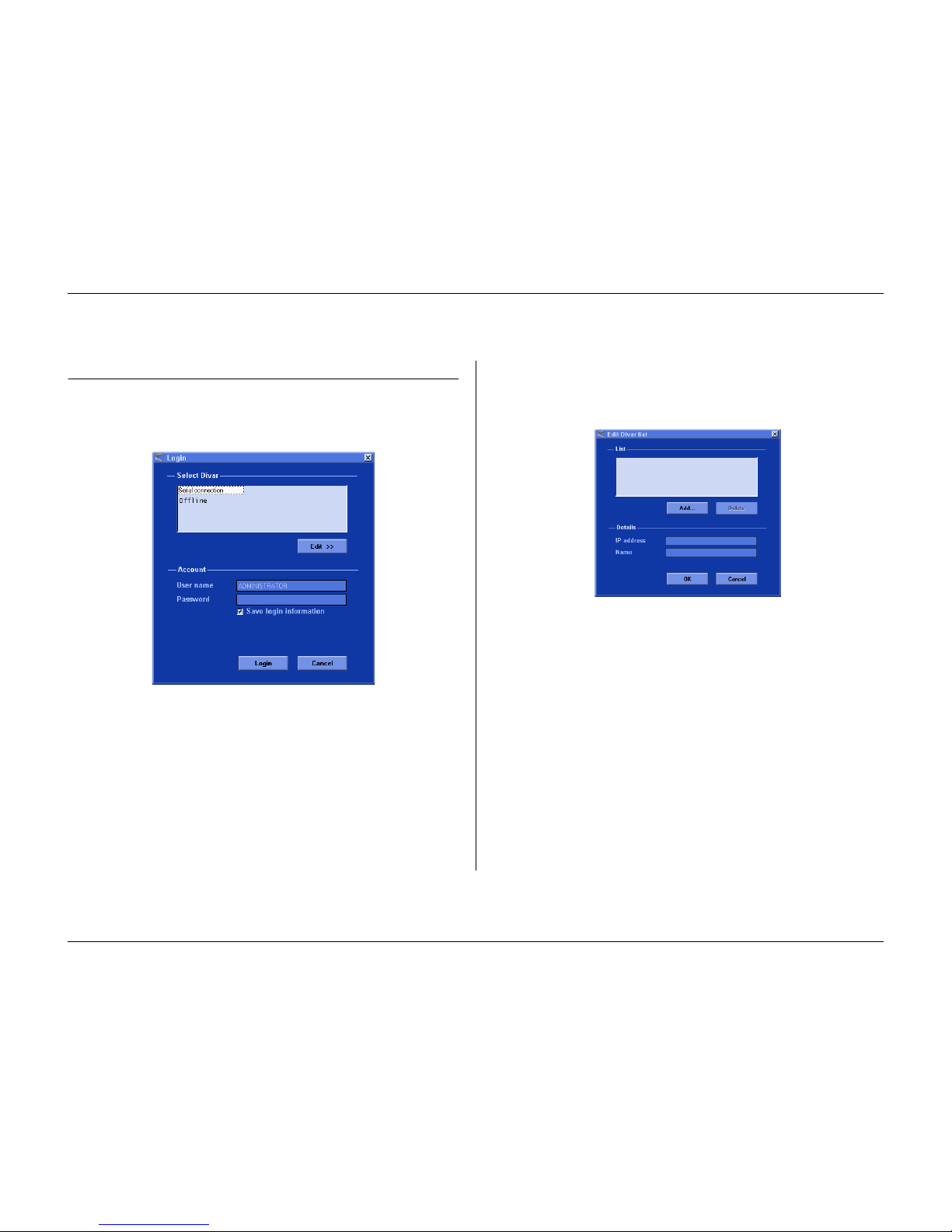
Using the Configuration Tool
Philips Communication, Security & Imaging 6-3
How to Log in
When you start the Configuration Tool as a stand-alone application via a
network, the
Login
window appears. (Click
Cancel
to discontinue login and
exit the application.)
When the Configuration Tool application is started for the first time, the Divar
list is empty. You must first add a Divar to the list. To add a Divar to the list or to
modify a Divar entry, click
Edit >>
(see following paragraph).
To control a particular Divar:
1.
Select the Divar you want to control.
2.
Type your user name and password.
> The user name and password to be filled-in are set in the System settings/
Connectivity/Network access menu of the Divar itself.
3.
Click Login.
To modify the Divar list
The
Edit Divar list
window allows you to add Divars to the list or delete Divars
from the list.
To add a Divar to the list:
1.
Click Add . . .
2.
Enter the IP address or nickname of the new Divar.
> The IP address to be filled-in is set in the System settings/Connectivity/Network setup
menu of the Divar itself.
3.
Type a name in the Name box or retrieve it from the Divar by checking the
Retrieve from Divar box.
4.
Click OK.
To delete a Divar from the list:
1.
In the list, select the Divar you wish to delete.
2.
Click Delete.
> The selected Divar is removed from the list.
Page 58
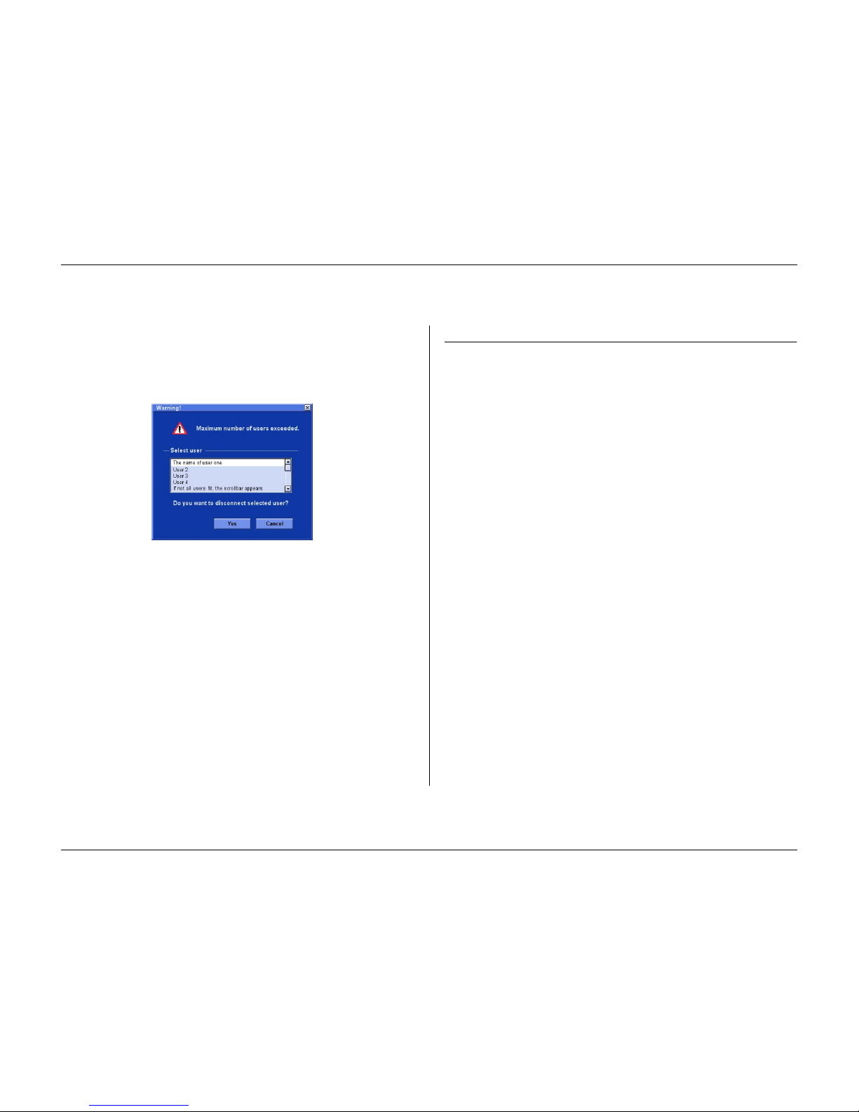
Using the Configuration Tool
6-4 Philips Communication, Security & Imaging
Maximum number of users
If the maximum number of users for the Control Center is exceeded, a window is
displayed. An administrator can use this window to force off a user. The list
shows all users that are currently logged in.
To disconnect a user:
1.
Select a user in the list.
2.
Click Ye s .
Menu structure differences
The Configuration Tool allows you to access and use menu items of the unit.
These menu items are explained in Chapter 5. Although the items are the same,
the menu structure is slightly different in the Configuration Tool:
• The History menu item is removed from the menu tree structure and is now
accessed via the Event log button.
• The Disk manager submenu is replaced by the Storage setup item of the
menu tree structure in the Configuration Tool.
As a result of the windows interface, selection and editing of some functions with
the Configuration Tool is different to the methods used on the unit itself. For
example, scroll bars are used instead of the arrow keys, the motion area selection
interface is simpler, and the Calendar edit item of the Profiles menu uses a color
code to add profiles to the calendar. The Configuration Tool interface, although
different, is intuitive and does not change the functionality of the menu items.
Page 59
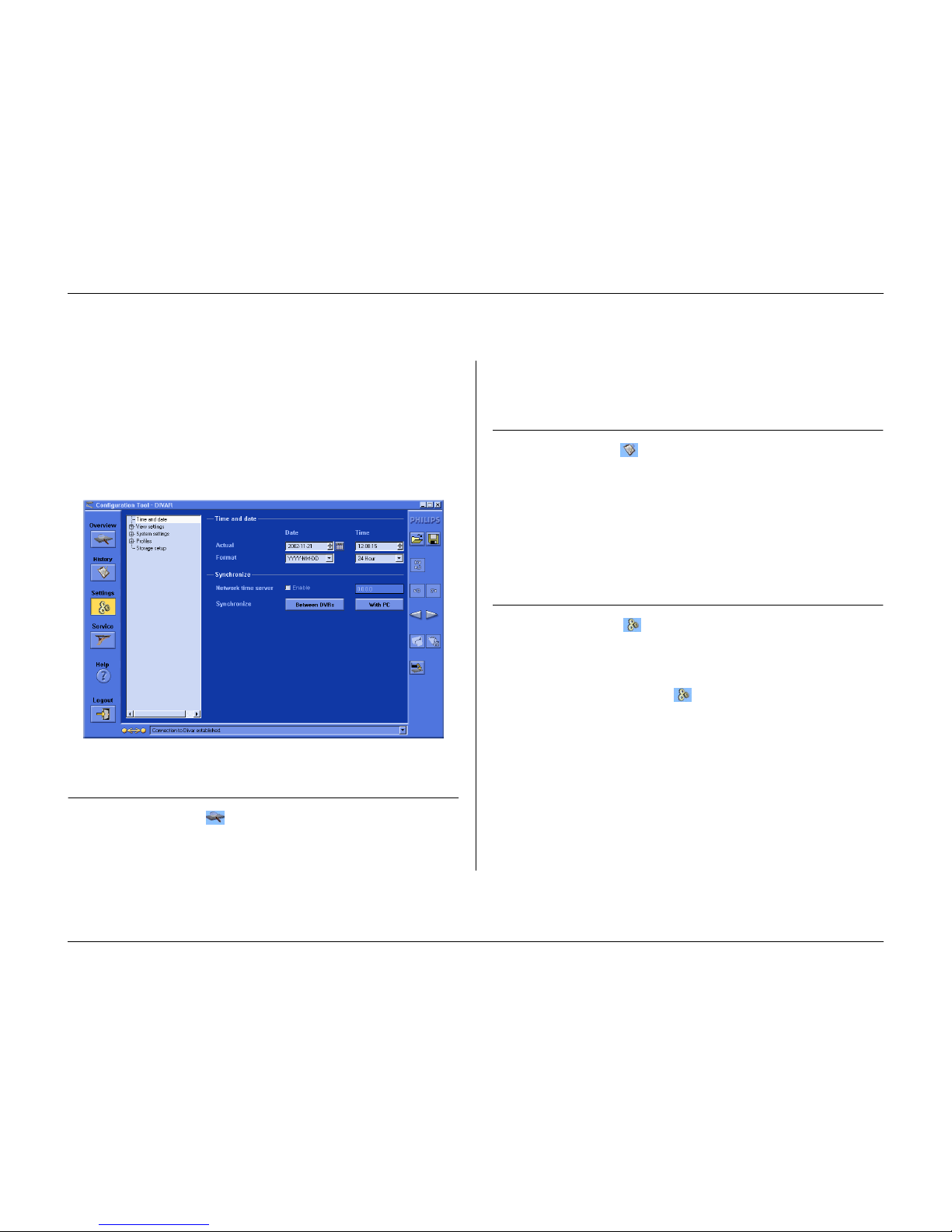
Using the Configuration Tool
Philips Communication, Security & Imaging 6-5
Introducing the main window
The Configuration Tool window is divided into 3 panes. The buttons in the left
pane are always available. Clicking one of these buttons changes the contents of
the center pane. The buttons in the right pane are control buttons that give you
direct access to various tasks.
Overview button
Click the
Overview
button to get general information about the Divar that
is connected.
History button
Click the
Histor y
button to display a list of events in the center pane. This
list can be filtered to show only those events you want to see.
• Fill in the date/time values to restrict the period for viewing events.
• Uncheck those type of events that you do not wish to see.
The latest event is shown first. If a date or time has been changed, the original
values are also displayed. Press
More
to see more events.
Settings button
Click the
Settings
button to display the menu for configuring the Divar.
The menu tree structure and the selected submenu is shown in the center pane.
Using the Menu tree
When you click the
Settings
button , the menu tree is displayed on the left
of the center pane. Use this tree to navigate through the menu system.
• Click + to expand the branch structure.
• Click - to collapse it.
• Click an entry to display the parameters for that menu item.
• Select the values you want for the parameters.
• These values are updated immediately.
Page 60
Using the Configuration Tool
6-6 Philips Communication, Security & Imaging
Service button
Click the
Service
button to get a list of diagnostic messages and to access
the firmware update function. This function is only available if you are
connected to the unit via a serial connection and is password protected.
Help button
Click the
Help
button at any time to get help. A pop-up help window
appears.
Logout button
To return to the Control Center application or to log on to different unit, click
the
Logout
button .
Using the control buttons
The right side of the main window has several buttons that allow you to perform
common tasks quickly:
Import / Export
All settings that you set in the Configuration Tool can be saved in a file that is
stored on the PC disk. You can save as many of these files as you like, just give
them different names. The settings in these files can be loaded back into the
Configuration Tool either completely or in subgroups. Although these files are
stored as text files and can be viewed with a text viewer, do not change or edit
them as this makes them unusable.
Import
1.
Click the import button to open a settings file.
2.
In the dialog box, select the location and name of the file you want to open.
3.
Select the groups of settings you want to load and click OK.
4.
The selected settings are downloaded to the unit immediately
Export
1.
Click the export button to save the current settings in a PC file.
2.
In the dialog box, select the location and enter a name for the file you want to
save.
3.
Select the groups of settings you want to save and click OK to save the settings.
Refresh
Click the refresh button to refresh the content of the current page settings
only.
Page 61
Using the Configuration Tool
Philips Communication, Security & Imaging 6-7
Undo / Redo
Click these buttons to undo or redo your last action. Up to 100 actions
can be undone.
Previous / Next
Use these buttons to move through the settings menu.
Click the previous button to go back to the page that was active before the
current page.
Click the next button to activate the next page in the menu system.
Print
When the Overview or Event log page is active, you can print the complete
contents of the page or list.
1.
Click the print button to print the current settings.
2.
Click OK to print.
Save
When the Overview or Event log page is active, you can save the complete
contents of the page or list.
1.
Click the save button to save the current settings in a PC file.
2.
In the Save dialog box, enter a file name and location.
3.
Click OK to save.
The information is saved in a text file.
Clear
Click the clear button to set all settings on the active page to their default
values.
Page 62

Using the Configuration Tool
6-8 Philips Communication, Security & Imaging
Page 63

Philips Communication, Security & Imaging 7-1
CHAPTER 7
Menu default values
The table on the following pages lists the items of the menu system of the unit
with default values. The righthand column of the table gives the default values of
these menu items. These values are restored when the
Factory defaults
item of
the
System settings
menu is selected.
Page 64
Menu default values
7-2 Philips Communication, Security & Imaging
Level 1 Level 2 Level 3 Level 4 Level 5 Default value
History
Show alarms Ye s
Show motions Ye s
Show network
connectivity
Ye s
Show errors Ye s
Time / Date Time format 24-hour (PAL)
12-hour (NTSC)
Date format YYYY-MM-DD
Synchronize Use timer server No
IP address 0. 0. 0. 0
View Settings
Camera setup
Camera name
Select input 01 . . . 16
Title CAMERA 1...CAMERA 16
Camera lock-out
Enter password (only when set)
Camera list No cameras locked
Set password No password set
Camera control
Auto camera contrast On
Adjust contrast 0
Camera controllable No cameras selected
Sequences
List Fullscreen monitor A All cameras connected
Page 65
Menu default values
Philips Communication, Security & Imaging 7-3
List Fullscreen monitor B All cameras connected
Dwell time monitor A 5 seconds
Dwell time monitor B 5 seconds
Configure Monitors
Display titles monitor A On
Display titles monitor B On
Display time / date monitor A On
Display time / date monitor B On
Status position Bottom; 0
Text intensity White; clear
Cameo border intensity Black
Exit menu on alarms No
System Settings
Language English
Recording Setup
Record mode Continuous
Overwrite protection None
Pre-event time 10 sec.
Disk Full Alarm Setup
Disk Full warning 95%
Disk Full alarm 1 min.
Output relay None
Beeper Disable
Playback Setup
List of (camera, block after) No block
Event Setup
Alarm dwell time 5 seconds
Level 1 Level 2 Level 3 Level 4 Level 5 Default value
Page 66
Menu default values
7-4 Philips Communication, Security & Imaging
Trigger dwell time 5 seconds
Input Setup
Output relay Relay 1
Beeper Enable
Display monitor A
Camera pre-positions None/PP01
Display monitor B
Camera pre-positions None/PP01
Motion Setup
Output relay None
Beeper Disable
Video loss Setup
Display monitor A Yes
Display monitor B No
Output relay Relay 2
Beeper Enable
History log setup
Log alarms Ye s
Log motions Ye s
Log video loss Ye s
Log errors Ye s
Log network Ye s
Connectivity
Keyboard access
Keybo ar d 1 Bo th
Keybo ar d 2 Bo th
Keybo ar d 3 Bo th
Level 1 Level 2 Level 3 Level 4 Level 5 Default value
Page 67
Menu default values
Philips Communication, Security & Imaging 7-5
Keybo ar d 4 Bo th
Network setup
DHCP Yes
DVR name DIVAR
Default gateway 0. 0. 0. 0
Bandwidth limit 100 MBPS
Network access
IP Range
List of IP addresses 0. 0. 0. 0 -
255.255.255.255
List of users
User name ADMINISTRATOR,
USER2...6
User rights Playback
User password No password
Expand system
DVR ID 1
First camera number 1
Com port
Connect to CCL
Baudrate 9600
Parity None
Bits 8
Stopbits 1
RTS /C TS On
Licenses
Simultaneous users 1
Level 1 Level 2 Level 3 Level 4 Level 5 Default value
Page 68
Menu default values
7-6 Philips Communication, Security & Imaging
Input and Output
contacts
Inputs N/O
Outputs N/O
Profiles
System behavior
Event handling
Select profile 1
Inputs enable Enabled for connected
cameras
Inputs alarm Enabled for connected
cameras
Motion enable Disable all
Motion alarm Disable all
Video loss enable Enabled for connected
cameras
Auto acknowledge alarms Yes
Output handling
Select profile 1
Relay enable Relays 1 and 2 enabled
Beeper Enable
Recording setup
Normal
List all cameras, quality, IPS Medium, 1IPS
Input
Cameras not in alarm, IPS No change
Level 1 Level 2 Level 3 Level 4 Level 5 Default value
Page 69
Menu default values
Philips Communication, Security & Imaging 7-7
Recording duration 30 seconds
Motion
Cameras not in alarm IPS No change
Recording duration 15 seconds
Access restrictions
Select profile 1
Local playback password Disable
User 2 Access
User 3 Access
User 4 Access
User 5 Access
User 6 Access
Copy system behavior
Copy from None
Copy to None
Advanced menus No
Level 1 Level 2 Level 3 Level 4 Level 5 Default value
Page 70
Menu default values
7-8 Philips Communication, Security & Imaging
Page 71

Philips Communication, Security & Imaging 8-1
CHAPTER 8
Technical specifications
The following pages give the technical specifications of the unit.
Page 72

8-2 Philips Communication, Security & Imaging
Electrical
Voltage and Power
All models 100-240 VAC; 0.7-0.3A, 50/60Hz
Video
Video standard: PAL/NTSC auto-detect
Resolution: 720 x 576 PAL - 720 x 484 NTSC
AGC: Automatic adjustment or manual adjustment of gain for
each video input
Digital Zoom: 2 or 4 times
Compression: WAVELET
Inputs: composite video 0.5-2Vpp, 75 ohm, automatic termination
Outputs: 1Vpp, 75 ohm, sync 0.3 V ± 10%
Alarm Handling:
Inputs: 6, 9 or 16 configurable NO/NC
max. input voltage 40 VDC
Outputs: 4 relay outputs, configurable NO/NC
max. rated 30 VAC - 40 VDC - 0.5A continuous -10VA
Control
RS232: Output signals according EIA/TIA-232-F
max. input voltage ±25V
Keyboard input: Conform RS485, max. signal voltage ±12V,
supply 11V-12.6V at max. 400mA
Keyboard output: Conform RS485, max. signal voltage ±12V
Bi-Phase: Impedance 128 ohm, max.
overvoltage protection ±40V,
max. cable length 1.5km
Connectors
Video inputs: 6, 9 or 16 looping BNC, auto-terminating
Ethernet: RJ45 shielded, 10/100 BaseT according IEEE802.3
Monitors: BNC (2), MON-A multiscreen, MON-B spot/alarm
Alarm connectors: Screw terminal input
Bi-Phase: Screw terminal output
RS232: DB9 male
Keyboard input: RJ11 (6-pin)
Keyboard output: RJ11 (4-pin), conform RS485, 30 units max.
SCSI: HD 50-pin, max. 7 connected ultra SCSI devices,
20Mbytes/sec, terminated internally
Page 73

Philips Communication, Security & Imaging 8-3
Storage
Hard Disks: 80GB -160GB - 320GB
Expandable via SCSI-2 HD50-pin, up to 7 external storage
arr ays : t yp e DVAD or DVAS .
File sizes: High quality: 40Kb
Medium quality: 24Kb
Standard quality: 16Kb
Record Rate (IPS): NTSC: 60 total, configurable per camera: 30, 15, 10, 7.5, 6,
5, 4, 3, 2, 1, ½, 1/5, 1/10, 0, Never
PAL: 50 total, configurable per camera: 25, 12.5, 8, 6, 5, 4,
3, 2, 1, ½, 1/5, 1/10, 0, Never
Recording Resolution: 720 x 288 PAL - 720 x 242 NTSC
Display Modes:
Monitor A: Full, full sequence, quad, quad sequence, multiscreen,
alarm call-up (live and playback)
Monitor B: Full, full sequence and alarm call-up
Recording Modes:
Linear, Continuous, Continuous with conditional overwrite.
Mechanical
Dimensions: 442 x 315 x 45 mm / 17.4 x 12.4 x 1.8 inch
Weight: approx. 5.8 kg / 12.8 lbs
Rack Mount Kit (Included): For mounting one unit in an EIA 19-inch rack.
Environmental
Temperature: Operating: +0°C to +45°C (+32°F to +113°F)
Storage: -25°C to +70°C (-13°F to +158°F)
Relative humidity: Operating: <93% non-condensing
Storage: <95% non-condensing
Electromagnetic Compatibility
EMC requirements: USA: FCC Part 15, Class B
EU: EMC directive 89/336/EEC
Immunity: EN50130-4
Emission: EN55022 Class B
Harmonics: EN61000-3-2
Voltage fluctuations: EN61000-3-3
Safety: USA: UL6500 2nd edition
EU: CE, EN60950: 2000
Canada: CAN/CSA - E60065-00
Accessories (Optional)
KBD-Digital Intui-Key keyboard with joystick
LTC 8557 Keyboard Extension Kit
DVAD LP Storage Array
DVAS RAID Storage Array
LTC 2605/91 Video manager
LTC 8782 Bi-phase code translaters
LTC 2604 Keyboard port expander
DVRSEU5 Software license for 5 simultaneous users
DVRSEU5x5 Packet of five DVRSEU5 licenses
Page 74

8-4 Philips Communication, Security & Imaging
 Loading...