

Philips DDL172LKCC0/97, DDL172LKCG0/97, DDL172LKCS0/97, DDL172LKCR0/97, DDL172LKCB0/97 user manual


Contents
1 Important information 02
Security
Caution
Disposal of used
products and batteries
2 Install your EasyKey 03
Packaging list
Exploded views
Pre-installation instructions
Installation steps
3 Get to know your
EasyKey 09
Outside escutcheon
Inside escutcheon
4 How to set up your
EasyKey 10
-Modify Ma ster PIN code
-User settings
-Delete a user
-System settings
-Extended functions
-System query
-Local Query
5 How to use your
EasyKey 16
Unlock
Unlock from outside
-With PIN code
-With ngerprint
-With card
Unlock from inside
-With handle
Lock
-Lock from out side
-Lock from inside
Deadlock from inside
Mechanical key opening
6 Other functions 18
Safe handle function
Restore to factory settings
One-button mute function
7 Meanings & Use of the
indicators 20
Door lock status indicator
Low battery indicator
Mute mode indicator
System lock indicator
8 Troubleshooting 22
Alarm types and alarm modes
How to apply an emergency power
How to replace batteries
1

1 Important information
2.Install your EasyKey
Security
◆Before using Philips EasyKey, please
read and understand all instructions.
Damage caused by non-compliance with
the instructions will not be covered by
warranty.
◆Use only the manufacturer-specied
accessories/components.
◆Use only the alkaline batteries the
product is equipped with, or use the
same specification type of alkaline
batteries.
◆Do not forcibly disassemble this product
to avoid tr iggering an alarm or damaging
the product.
◆Do not scrape the ngerprint sensor
with sharp objects, otherw ise it may cause
permanent damage.
◆Do not expos e product s to enviro nments
where there is water leakage or splashing.
◆Do not expose the product to corrosive
substances to prevent damaging the
protective cover.
◆Do not hang objects on the handle, in
case it might aect the normal use of the
lock.
◆Pleae clean t he product w ith a soft cloth .
◆Do not remove the battery during
sett ing up and operating.
◆Please let a professional technician
to install the door lock and follow the
installation guidelines provided.Do not
disassemble the lock by yourself. Keep the
relevant sealed stickers properly. Do not
easily disclose the password information.
◆Please modify the default master PIN
code immediately after nishing installing
and debugging, and keep the mechanical
key properly.
◆Please replace all the batteries
immediately if there is a low battery alarm.
Please make sure to correctly match the
poles (+/-) when installing the batteries.
Caution
◆Do not place the battery near re
sources to avoid explosion.
◆Do not use any emergency power
supply that does not meet the safet y
requirements to power up the product.
◆Do not connect the 2 poles of the
batteries with metals to avoid short circuit
which may lead to an explosion.
◆Please make sure any component
replacement is executed by Philips, Philips
authorized service center or professional
technicians.
◆Do not use acces sories or p arts tha t have
been produced by other manufacturers or
have not been spec ically recommended
by Philips. The use of such accessor ies and
parts may void your warranty.
Disposal of used products and
batteries
◆You can have your locks reclaimed at
Philips author ized service centers. You will
receive corresponding compensation if
your products meet our conditions.
◆Please familiarize yourself with the local
electronic product collection system.
◆Please follow local regulations and do
not discard used products into ordinary
household waste.
◆Proper disposal of used products can
help to avoid potent ial negative impacts
on the env ironment and human health.
◆Batter ies must not be disposed of with
ordinary household waste.
◆Please familiarize yourself with the local
regulations on batteries classication
recycling. Disposing of bat ter ies properly
can help avoid a negative impact on the
environment and human health.
Packaging list
This packaging list is for reference only. Please refer to the actual packaging
contents.
①Outside
escutcheon (including
silicone pad)
⑤Mounting plate ⑥User manual ⑦Quick start guide ⑧Warranty
EasyKey易锁
合格证
⑨Certicate of
Conformity
⑬ Installation kit ⑭Cleaning pad
②Inside escutcheon
(including
silicone pad)
EasyKey易锁
User Manual
⑩Smart door
card x2
③Drilling template ④Mortise
EasyKey易锁
Quick Start
Guide
EasyKey易锁
Warranty
Card
card
⑪Mechanical
key x2
⑫Batteries
Striker
2 3

Exploded Views
Pre-installation instructions
Step 1 | Check the door opening direction
This product can be installed on doors of 4 types of opening direct ions:
left-out pull, r ight-in push, right-out pull and left-in push.
Left-handle open Right-handle open
Indoor Indoor
1. Outside escutcheon
(x1)
2. Outside escutcheon
silicone pad (x1)
3. Connecting screw
tube (x3)
4. Square shaft
compressed spring (x2)
5. Square shaft (x2)
6. Split pin (x2)
7. Cylinder key
tailpiece (x1)
8. Mortise (x1)
9. Mortise anchor
screw (x4)
10. Mount ing plate (x1)
11. Mounting plate
anchor screw (x1)
12. Inside escutcheon
silicone pad (x1)
13. Inside
escutcheon (x1)
14. Inside escutcheon
anchor screw (x2)
15. Battery cover (x1)
16. Inside escutcheon
lower cover (x1)
17. Rotary knob
tailpiece (x1)
Left-in
Outdoor
Indoor Indoor
Outdoor Outdoor
push
Leftout pull
Step 2 | Change the handle direction
Remove the 2
1
cross recessed
countersunk head
screws in the
escutcheon
Rotate the handle
2
180 degrees
Outdoor
Put the 2 screws
3
back and tighten
them
Ri ghtin push
Ri ghtout pull
4 5

Step 3 | Change the latch bolt direction
You can change the direction of the latch bolt to adapt to doors of dierent
opening directions.
Inverting tailpiece
Directional screw
1. Push the inver ting tailpiece to the top.
Latch bolt
Attention
1. Choose a proper ins tal lat ion k it based on th e door t hickn ess;
2. The defau lt tool k it is applic able to doors of 38- 60mm thick. I f your do or thic kness is out of this
range, please contact us.
2. Press into the latch bolt and turn it 180
degrees, then pull out the latch bolt.
3. Push the tailpiece to the bot tom.
4. Change the direction of the direct ional
screw according to the internal and ex ternal
door opening requirements.
(Directional screws must be installed on the
inside of the door, that is, which side is the
direc tional screw and which side must be the
inner escutcheon)
Installation steps
The following installation steps apply to r ight-open doors. For left-open doors,
please read the chapter [Pre-installation instructions] carefully and make
needed adjustments.
Use the drilling template to drill
1
the needed holes on the door and
mount the mortise into the door.
Hook up the multi-lock latch bolt
2
when the mortise is inser ted.
(This step is unneeded when
installing wooden doors.)
Tighten the 4 anchor screws on
3
the mortise.
Pass the cable through the hole
5
on the door. The mechanical key
tailpiece needs to be inserted
into the t wo rotary holes on
the mor tise, so that the outer
escutcheon stays close to the
outside door.
Install the connecting screw tubes
4
and mechanical key tailpiece on the
outer escutcheon, and insert the
compressed spring and square shaft
into the handle hole (the compressed
spring faces the handle side).
Attention
The mechani cal key t ailp iece sh all be
appropri ately c ut as pe r the th ickne ss of
the door, and the s quar e shaf t, con nect ing
screw tube and ancho r screw t ube w ith the
appropri ate len gth sh all also be used.
Tighten the mounting plate w ith an
6
anchor screw against the inside of
the door.
6 7

Insert the compressed spring and
7
square shaft accordingly to the
outside escutcheon, then insert
the rotary knob tailpiece. Insert
the outside escutcheon connecting
cable and motor cable into the
corresponding holes on the inside
escutcheon, then align the rot ary
knob tailpiece on the inside
escutcheon with the square shaft
and insert it to make sure the inside
escutcheon is kept close to the
inside of the door.
Attention
Please hide t he extra
conne cti ng cab le into
the hol e of the do or.
Install the batteries, then the
9
battery cover and the inside
lower cover.
Tighten the 2 anchor screws.
8
Try the inside and outside
10
handles, the rotar y knob, the
mechanical key and check if all
components are well connected.
3 Get to know your EasyKey
Outside escutcheon
Keypad
1
Card reader
2
Mute button
3
4
Low battery indicator
Fingerprint sensor
5
Lever
6
Door st atus indicator
7
Reset button
8
Emergency power interface
9
Mechanical key hole
10
Inside escutcheon
Battery cabinet
1
2
Lever
3
Safe handle sw itch
4
Reset button
5
Extension module
Rotary knob
6
8 9
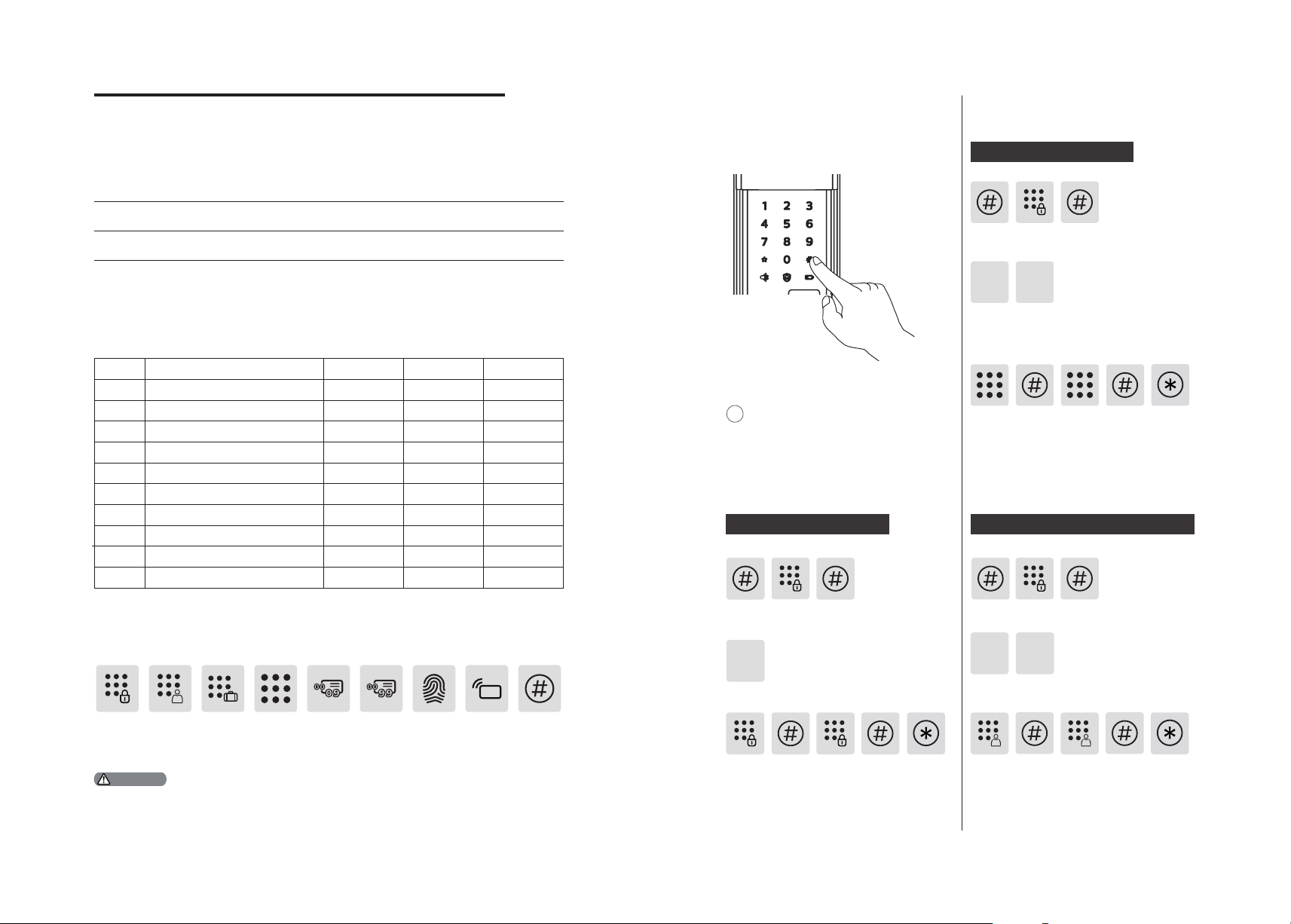
4. How to set up your EasyKey
Pre-setup Instructions:
◆There are 2 modes in the EasyKey: General mode and dual verication mode.
◆How to enter master mode:
User settings
Register a user PIN code
General mode
Unlock with a ny reg iste red
ident ity inform ati on
◆User Number
You can delete a single user informat ion by its user
number without having to delete ever ything.
◆You can record the user information in the follow ing table for future query.
Number
00
01
02
03
04
05
06
07
08
09
◆Icon annotation
Master
PIN code
1.Press [*] key t o retur n to the previous men u.
2. The default mast er PIN code is 123 45678.
One-t ime
user PIN
Attention
Name Fingerprint PIN Code Card
Visitor
User PIN
code
PIN
code
code
Dual verication mode
Unlock with a ny two of PIN
code, c ard an d ngerprint
User
number
00-09
User
number
00-99
Fingerprint Card
reader
# key
1
Press [#] key before inputting
any other numbers. Af ter hearing a
voice prompt of "Enter master PIN
code", enter your master PIN code
and conrm with [#]. Then you are in
master mode.
Modif y master PIN code
Press [#], enter ma ster PIN code and
press [#] to conrm.
1
Press [1] to mod ify master PIN code.
Enter the new master PIN code and press
[#] to conrm. Re-enter the new Master
PIN code and press [#].Af ter hearing a
voice prompt of “Succeeded”, press [*]
several times until you ex it ma ster mode.
Press [#], enter master PIN code and
press [#] to conrm.
2
Press [2] to enter user registration, then
press [1] to register a new user PIN code,
which will be automat ically numbered and
broadcasted by the system.
Enter a user PIN code of 6 to 12 digits
and press [#] to conrm. Then re-enter
it and pr ess [#] to conrm. Af ter hear ing
a voice prompt of “Succeeded”, press
[*] several times until you ex it master
mode.
Register a one-time user PIN code
Press [#], enter master PIN code and
press [#] to conrm.
1
2 2
Press [2] to enter user set tings, then press [2]
again t o enter one-t ime PIN co de regist ration .
Enter a one-time user PIN code of 6 to
12 digits and press [#] to conrm. Reenter and press [#] to conrm. After
hear ing a voice prompt of “Succeeded”,
press [*] several times until you exit
master mode.
10 11

Register a ngerprint
Delete a card
Press [#], enter ma ster PIN code and
press [#] to conrm.
2
3
4
2
Press [2] to enter user settings, then press [3]
to enter f ingerpr int reg istration. The system
will automatically number the fingerprint and
broadcast the number.
Place your nger against the sensor. Af ter
hear ing a voice prompt of “Take away
your nger and enroll again”, plea se take
away your nger and re-pl ace it against
the sensor. After hearing a voice prompt
of “Succeeded”, press [*] several times
until you exit master mode.
Register a card
Press [#], enter ma ster PIN code and
press [#] to conrm.
Press [2] to enter user adding, then press
[4] to enter card registration. The system
will automatically number the card and
broadcast the number.
Hold the card close to the card reader
until you hear a beep. After hear ing a
voice prompt of “Succeeded”, press [*]
several times until you ex it master mode.
User Information
Deletion
Delete a user PIN c ode
Press [#], enter ma ster PIN code and
press [#] to conrm.
1113
Press [3] to enter user deletion, then press [1] to
enter user PIN code delet ion. Press [ 1] again to
delete a s ingle user PIN code.
Enter the 2-dig it [user number] (00-09)
of the user PIN code that is to be deleted
and press [#] to conrm. Af ter hearing a
voice prompt of “Succeeded”, press [*]
several times until you ex it ma ster mode.
Delete all user PIN codes
Press [#], enter ma ster PIN code and
press [#] to conrm.
3
Press [3] to enter user deletion, then press [1] to
enter user PIN code delet ion. Press [2] to delete
all user PIN codes. Af ter hearing a voice prompt
of "Succeeded", press [*] several times until you
exit master mode.
删除一次性 用户密码
Delete a one-time user PIN code
Press [#], enter ma ster PIN code and
press [#] to conrm.
3
Press [3] to enter user deletion, then
press [ 2] to enter one-t ime user PIN code
deletion.
2
2
After hear ing a voice prompt of
“Succeeded”, press [*] several t imes until
you exit master mode.
Delete a ngerprint
Press [#], enter ma ster PIN code and
press [#] to conrm.
3 3 1
Press [3] to enter user deletion, then press
[3] again to enter ngerprint delet ion.
Press [1] to enter single nerprint delet ion.
Enter the 2-dig it [user number] (00-09)
of the ngerpr int that is to be deleted
and press [#] to conrm. Af ter hearing
a voice prompt of “Succeeded”, press [*]
several times until you ex it master mode.
Delete all ngerprints
Press [#], enter ma ster PIN code and
press [#] to conrm.
3 3
Press [ 3] to enter user d eletion, t hen press
[3] again to enter ngerprint delet ion.
Press [2] to delete all ngerpr ints. After
hear ing a voice prompt of "Succeeded",
press [*] several times until you ex it
master mode.
2
Press [#], enter ma ster PIN code and
press [#] to conrm.
3
4
Press [3] to enter user deletion, then
press [4] to enter card deletion. Press [1]
to delete a single card and then press [*]
several times until you ex it ma ster mode.
Delete all cards
Press [#], enter ma ster PIN code and
press [#] to conrm.
3
4
Press [3] to enter user deletion, then
press [4] to enter card deletion. Press [2]
to delete all cards. After hear ing a voice
prompt of "Succeeded", press [*] several
times until you ex it master mode.
System initialization
Open the battery cover, then long press
the [RES] with a sharp object for a long
time. After hearing the voice prompt to
restore the factor y settings, release the
[RES], then all user information will be
deleted.
1
2
12 13

Language Settings
Press [#], enter ma ster PIN code and press
[#] to conrm.
System settings
Switch to dual ver ication mode
5
Press [4] to enter system settings, then
[5] to enter time settings. Enter the time
and conrm with [#].
Attention
Directly enter 400# to start s ystem quer y.
Local Query
4
Press [4] to enter system settings, then
press [ 1] to enter language sett ings.
Adjust the la nguage as ne eded: For Chinese,
press [ 1]; for English, press [2]. After hearing
a voice prompt of “Succeeded”, press [*]
several times until you ex it ma ster mode.
The def ault l anguage is English.
Volume settings
Press [#], enter ma ster PIN code and
press [#] to conrm.
1
Attention
1
or
2
24
Press [4] to enter system settings, then
press [ 2] to enter volume sett ings .
or or
1
Adjust the volume as needed: For higher
volume, press [ 1]; for lower volume, press
[2]; for mute mode, press [3]. Af ter hearing
a voice prompt of “Succeeded”, press [*]
several times until you ex it ma ster mode.
Attention
The default volume is “higher volume”.
2
3
Press [#], enter ma ster PIN code and press
[#] to conrm.
1
3
or
2
4
Press [4] to enter system settings, then
press [3] to choose verication method.
For single verication, press [1]; for dual
vericat ion, press [2]. After hearing a
voice prompt of “Succeeded”, press [*]
several times until you ex it ma ster mode.
Date settings
Press [#], enter ma ster PIN code and
press [#] to conrm.
444
Press [4] to enter system settings, then
[4] to enter date set tings. Enter the date
and press [#] to conrm.
Time settings
Press [#], enter ma ster PIN code and
press [#] to conrm.
Extended Functions
Press [#], enter ma ster PIN code and
press [#] to conrm.
5
Press [5] to enter extended funct ions.
or
1
To join a network, press [1]. To exit a
network, press [2]. Before sett ing up the
extended functions, please download
and open the Philips EasyKey APP on your
mobile phone.
Attention
The extended functions are optional.
System Query
Secur ity Code query
Press [#], enter ma ster PIN code and press
[#] to conrm.
6
Press [6] to enter system quer y, then
press [ 1] to get the ser ial number (security
code) automatically broadcasted.
2
1
Press [#], enter ma ster PIN code and
press [#] to conrm.
6
Press [6] to enter system quer y, then
press [ 2] to get the soft ware version
automatically broadcasted.
Directly enter 114 # to st art n ative quer y.
2
Attention
Record query
Press [#], enter ma ster PIN code and press
[#] to conrm.
3
6
Press [6] to enter [System Query], then press
[3] to start record query.
14 15

5.How to use your EasyKey
Lock | Lock from outside/inside
Unlock | Unlock from outside
With User PIN code With ngerprint With card
1
Tou ch
keypad
2
Enter a
PIN code
2
Press the
handle
1
Card
reader
3
Press the
handle
1
Touch the keypad and
light up the buttons.
2
Enter the registered
user PIN code and press [#]
to conrm.
3
After hearing a voice
prompt of “Door opened”, press
the handle to open the door.
1
Fingerprint
Place your registered
1
nger properly on the sensor.
After hear ing a voice
2
prompt of “Door opened”,
press the handle to open
the door.
Place your registered
1
card on the card reader.
2
After hear ing a voice
prompt of “Door opened”,
press the handle to open
the door.
Unlock | Unlock from inside
2
Press the
handle
Lock from outside
Lift the handle after closing
the door. Then the bolt will
pop up and door w ill be
locked.
Lock from inside
Lift the handle after closing
the door. Then the bolt will
pop up and door w ill be
locked.
Deadlock from inside
With handle
Philips EasyKey employs indoor
fast opening motise allowing
you to directly press the handle
to unlock.
Attention
When yo u want to o pen th e door
from in side , plea se make sure the
safe ha ndle switc h is togg led to
green s cale a nd the s afe handle
function is disabled.
When the EasyKey is locked, you can
rotate the knob to red scale (as shown
in the lef t image) to enable inside
deadlock. Also rotating the knob to
green scale can disable the func tion.
16 17

Mechanical key opening
Restore factory settings: one button to restore
to factory settings
Push
1
Cut the box and take
out the key shell . Push the
cover as ide and reveal the
key itse lf.
Attention
It‘s sugges ted that do not use the me chanical key for daily unloc king. Use th e key for em ergencie s,
for exa mple wh en the b attery is d ead, w hen you forget the PIN cod e, or wh en the s ystem fails to
work properly.
2
Inser t the key itself
into the key hole and
keep the key and key
shell vert ical to each
other. Rotate the key shell
towards the handle for
90° unt il it becomes close
to the door surface.
3
Rotate the key shell
downwards for 180° to
make the key shell parallel
to the ground. Then rotate
the key shell hor izont ally
towards the handle to
unlock the door.
6 Other functions
Safe handle function: Lock the handle
from inside
Function:
Lock the handle from inside and prevent
unlock ing from inside.
How to use:
1. Enable safe handle function: Toggle
the sw itch to red scale.
2.Disable safe handle funct ion: Toggle
the sw itch to green scale.
Safe
handle
switch
Function:
Empty all user information and return to factory
settings.
How to use:
Long press the [RES] button for 5 seconds, and
all the user informat ion w ill be emptied. The
lock will be restored to factory sett ings.
One-button mute function
Function:
Use only one button to mute the lock by turning
o the voice guide. Applicable to the scenes
where you don’t want to disturb your family.
How to use:
1. Mute: When the system is awake, long press
the [Mute] button for 2 seconds to enter onetime mute mode. The button will glow green.
2. Unmute: When the system is awake, long
Mute button
press the [Mute] button for 2 seconds to restore
the voice guide. The but ton w ill glow white.
18 19

7 Meanings & Use of the indicators
Lock status indicator
Lock
status
indicator
Low battery indicator
Low battery
indicator
Colors of the light and the corresponding
meanings:
Blue: Af ter the system wakes up, the
light will glow blue, indicating that you
can operate the lock.
Green:After the door is unlocked, the
light will glow green, indicating that
the door has been opened.
Red:After the door is locked, the light
will glow red, indicating that the door
has been closed.
Colors of the light and the corresponding
meanings:
Red:After wak ing up, the system will
run an automat ic examination on the
battery voltage. If the voltage is too
low, the light will ash in red and there
will be a voice prompt of “Low battery.
Please replace all batteries”.
Mute mode indicator
Mute mod e indica tor
System lock indicator
3 ashes 2 ashes 1 ash
3 minutes
2 minutes
Color s of the light an d the corre spondin g
meanings:
1.White: Indicates the mute mode is o.
2.Green:Indicates the mute mode is on.
If there are 10 consecut ive
and incorrec t inputs of any
of the 3 t ypes of ver ica tion
method (ngerprint/PIN
code/card), this t ype of
vericat ion will be locked
for 3 minutes. You can
unlock w ith the other
2 types of verication
method.
Attention
Only wh en inpu tt ing the
1 minute
locked t ype of veri cat ion w ill
the system g ive such a prompt.
20 21

8 Troubleshooting
Types of alarms and alarm modes
Low battery alarm, prompting you to replace the batteries in time
Triggering: After wak ing up, the system will
run an automat ic examination on the battery
voltage. If the volta ge is too low, the lock give
an alarm and a voice prompt of “Low battery.
Please replace all batteries”.
Alarm mode: A voice prompt of “Low battery.
Please replace all batteries” dur ing unlocking.
Turning o: The alarm w ill be automatically
turned o.
Mechanical key opening alarm
Triggering: The lock is opened by a key
Alarm mode: Continuous repeated alarms
Turning o: The alarm w ill be automatically
turned o or after a successful verication.
How to use an emergency power
When the battery voltage is insucient,
and the door ca nnot be power up from
the out side, you can power the lock
through the Micro USB interface by using
Reset
button
Emergency
power interface
a 5V power bank as an emergency power
supply. Af ter opening the door lock,
please repl ace the batteries immediately.
In case of a system crash and it's
impos sible to open t he door from o utside,
please press the Reset button and then
relea se to let it reboot automatically.
How to replace batteries
Anti-dismantle alarm
Triggering: The door is pried open and there
is no t in the door.
Alarm mode: Continuous repeated alarms.
Turning o: Auto-close, or close after a
successful key verication, or close af ter the
normal indoor unlock.
22 23
The lock is powered by four 1.5V alkaline
batteries. There are two set s of work ing
power inside the battery cabinet. Eight
batteries can be put in to extend the
battery life and reduce batter y replacement
frequency. The battery cabinet is located at
the upper end of the inside escutcheon. By
pushing the cover upwards, you can remove
it and then replace the batteries.

Philips and the Philips Shield Emblem are registered trademarks of Koninklijke
Philips N.V. and are used under license. This product ha s been manufactured by
and is sold under the responsibility of Shenzhen Conex Intelligent Technology
Co., Ltd. and Shenzhen Conex Intelligent Technology Co., Ltd. is the warrantor in
relat ion to this product.
Version:2.0
 Loading...