

Philips DCP-750 Service manual
DVD Portable Player DCP750
All version
Service Manual
©Copyright 2005 Philips Consumer Electronics B.V. Eindhoven, The Netherlands
All rights reserved. No part of this publication may by reproduced, stored in a
retrieval system or transmitted, in any form or by any means, electronics,
mechanical, photocopying, or otherwise without the prior permission of Philips
TABLE OF CONTENTS
Chapter
Technical Specification & Service Tips…………..……….. 1
Safety Instructions…………………………………………….. 2
Instruction for Use……………………………………………… 3
Mechanical Instructions………………………………………. 4
Troubleshooting …………………………………………………5
Overall Block Diagram…………………………………………. 6
Electrical Diagram……………………………………………… 7
Component Layout Diagram ………………………………… 8
Exploded View Diagram & Service Part List………………. 9
Revision List……………………………………………………. 10
3141 785 31625
Version 1.5
1.0 TECHNICAL SPECIFICATION
General
Dimensions (W x H x D): 210 x 39 x 178mm
Weight: 1.1kg
Power supply: DC 6.2-15.0V
Power consumption: 9W
Operating temp. & RH: -10-50degC / 40-90%
Video System NTSC / PAL / AUTO
Audio System
Output voltage 1kHz: 2+/-0.2V
THD 20-20kHz (%): </=3%
Dynamic range: >/=70dB
Signal/Noise ratio: >/=70dB
Frequency response (2020kHz):
Channel Separation 1kHz >=60dB
Channel Balance 1kHz <2dB
Current consumption
DC-IN SUPPLY (9V)
Battery Charging Current 450 +/- 50mA
Power Off
Playback with TFT on
Playback without TFT on
Playback time
Headphone out (headphone output load 2x16 ohm)
Maximum output power:
Frequency response:
SNR (A-wght):
THD (0.2-20kHz):
Left-Right Channel
Separation:
Left-Right Channel
Balance:
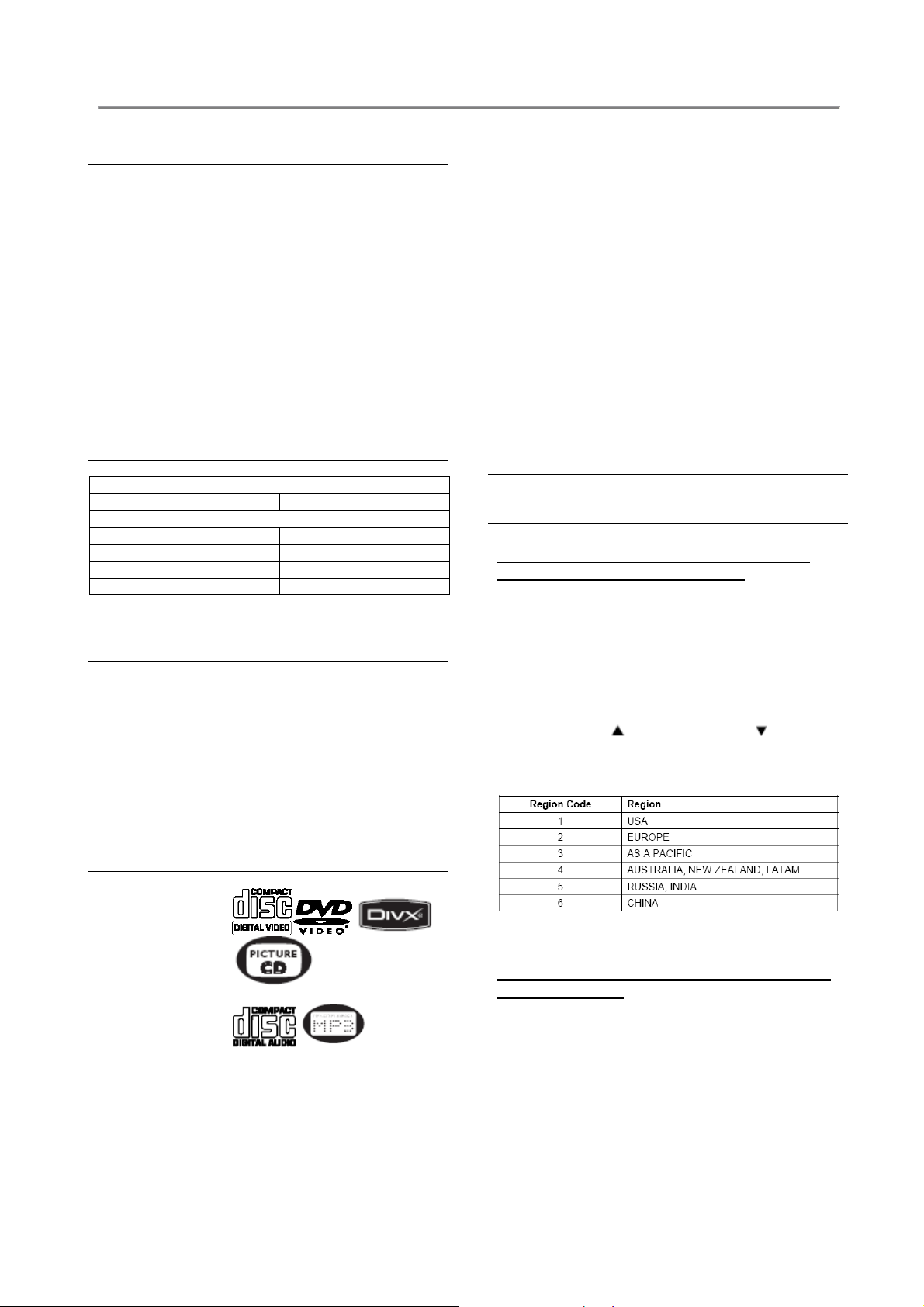
Supported disc type
Video Playback
Formats:
Audio Playback
Formats:
+/-1dB
BATT. SUPPLY
10mW
+/-1dB
>70dB
1%
>/=50dB
</=1dB
Playback disc type: DVD, Picture-CD,
Video Playback Format: DVD / VCD / JPEG /
Audio Playback Format: CD/MP3, MP3-DVD,
Disc Diameter 12cm
Pixel specification
Zero bright-dot & max. 3 dark-dots
Factory Service Mode (FSM)
SVCD, Video CD, MP3CD, CD-R/CD-RW,
WMA-CD, DVD-R, DVDRW, DVD+R, DVD+RW,
SD/MMC Card
MPEG4 / DIVX3,4,5,6
WMA
To check the software version and change
region code of your DVD Portable
1. Power ON the DVD player and open the DVD
door
2. Press the “SETUP” button on remote control,
then select the “Preference MENU”
3. Press the remote button in the sequence as
9 -> 6 -> 5 -> 3
4. The LCD display showed the existing region
code. Press
(navigation up) or
(navigation down) repeatedly to select the
number from 0 to 6.
5.
Refer below table for your region code setting
Select “0” setting = Region Free (confidential)
Procedure on how to upgrade the software of
the DVD Portable
For the best performance of your DVD Portable.
Check www.philips.com/support for latest
software upgrades available.
A) By CD-ROM
1. Download the “PHILIPS.BIN” file from the Philips
support site
2. Unzip the file and then burn it into a CD-ROM to
make a disc for upgrade

1.0 TECHNICAL SPECIFICATION
3. CD-ROM disc name must be “PHILIPS”
(otherwise it will not be recognized as a disc for
upgrade)
4. Power on the Portable DVD Player with AC/DC
adaptor
5. Play CD-ROM for firmware upgrade
Warning: Do not unplug the AC adaptor during
firmware upgrade to prevent flash corrupt of the
set!!
6. Once upgrade is completed, the player will restart
automatically and observed PHILIPS LOGO on the
screen.
7. Open the DVD door to remove the disc
B) By SD/MMC Card
1. Download the latest “PHILIPS.BIN” from the
Philips support site
2. Unzip the files and then copy into SD/MMC Card
for upgrade
3. Power on the Portable DVD Player with AC/DC
adaptor
4. Change the set from DVD mode to Card mode by
press the “Card” button on remote control
5. Insert the SD/MMC Card on the card slot
6. The set will automatically upgrade
Warning: Do not unplug the AC adaptor or remove
SD/MMC Card
flash corrupt of the set!!
7. Once upgrade is completed, the player will restart
automatically and observed PHILIPS LOGO on the
screen.
8. Remove the card from the set
Note: If you want to use the same card for audio / video
playback on the set, please delete the “PHILIPS.BIN”
first. Otherwise, it will be recognized as for software
upgrade again.
during firmware upgrade to prevent
2.0 SAFTETY INSTRUCTIONS
WARNING
GB
All ICs and many other semi-conductors are
susceptible to electrostatic discharges (ESD).
Careless handling during repair can reduce life
drastically.
When repairing, make sure that you are
connected with the same potential as the mass
of the set via a wrist wrap with resistance.
Keep components and tools also at this
potential.
F
ATTENTION
Tous les IC et beaucoup d’autres
semi-conducteurs sont sensibles aux
décharges statiques (ESD).
Leur longévité pourrait être considérablement
écourtée par le fait qu’aucune précaution n’est
prise à leur manipulation.
Lors de réparations, s’assurer de bien être relié
au même potentiel que la masse de l’appareil et
enfiler le bracelet serti d’une résistance de
sécurité.
Veiller à ce que les composants ainsi que les
outils que l’on utilise soient également à ce
potentiel.
ESD
D
WARNUNG
Alle ICs und viele andere Halbleiter sind
empfindlich gegenüber elektrostatischen
Entladungen (ESD).
Unsorgfältige Behandlung im Reparaturfall kan
die Lebensdauer drastisch reduzieren.
Veranlassen Sie, dass Sie im Reparaturfall über
ein Pulsarmband mit Widerstand verbunden
sind mit dem gleichen Potential wie die Masse
des Gerätes.
Bauteile und Hilfsmittel auch auf dieses gleiche
Potential halten.
WAARSCHUWING
NL
Alle IC’s en vele andere halfgeleiders zijn
gevoelig voor electrostatische ontladingen
(ESD).
Onzorgvuldig behandelen tijdens reparatie kan
de levensduur drastisch doen verminderen.
Zorg ervoor dat u tijdens reparatie via een
polsband met weerstand verbonden bent met
hetzelfde potentiaal als de massa van het
apparaat.
Houd componenten en hulpmiddelen ook op
ditzelfde potentiaal.
I
AVVERTIMENTO
Tutti IC e parecchi semi-conduttori sono
sensibili alle scariche statiche (ESD).
La loro longevità potrebbe essere fortemente
ridatta in caso di non osservazione della più
grande cauzione alla loro manipolazione.
Durante le riparazioni occorre quindi essere
collegato allo stesso potenziale che quello della
massa dell’apparecchio tramite un braccialetto
a resistenza.
Assicurarsi che i componenti e anche gli utensili
con quali si lavora siano anche a questo
potenziale.
GB
Safety regulations require that the set be restored to its original
condition and that parts which are identical with those specified,
be used.
NL
Veiligheidsbepalingen vereisen, dat het apparaat bij reparatie in
zijn oorspronkelijke toestand wordt teruggebracht en dat onderdelen,
identiek aan de gespecificeerde, worden toegepast.
F
Les normes de sécurité exigent que l’appareil soit remis à l’état
d’origine et que soient utiliséés les piéces de rechange identiques
à celles spécifiées.
D
Bei jeder Reparatur sind die geltenden Sicherheitsvorschriften zu
beachten. Der Original zustand des Geräts darf nicht verändert werden;
für Reparaturen sind Original-Ersatzteile zu verwenden.
I
Le norme di sicurezza esigono che l’apparecchio venga rimesso
nelle condizioni originali e che siano utilizzati i pezzi di ricambio
identici a quelli specificati.
“Pour votre sécurité, ces documents
doivent être utilisés par des spécialistes agréés, seuls habilités à réparer
votre appareil en panne”.
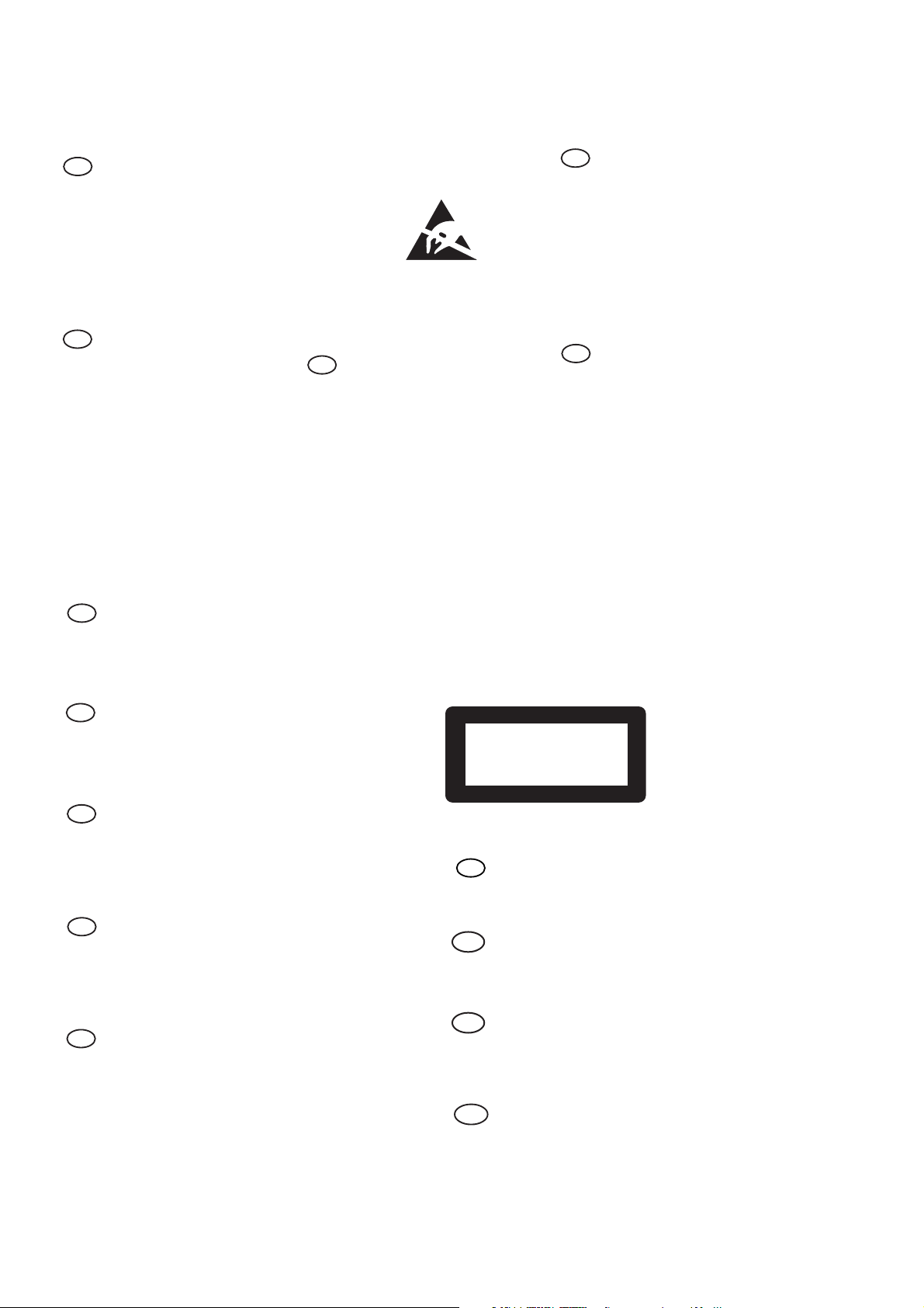
CLASS 1
LASER PRODUCT
GB
Warning !
Invisible laser radiation when open.
Avoid direct exposure to beam.
S
Varning !
Osynlig laserstrålning när apparaten är öppnad och spärren
är urkopplad. Betrakta ej strålen.
Varoitus !
SF
Avatussa laitteessa ja suojalukituksen ohitettaessa olet alttiina
näkymättömälle laserisäteilylle. Älä katso säteeseen!
3122 110 03420
"After servicing and before returning set to customer perform a
leakage current measurement test from all exposed metal parts to
earth ground to assure no shock hazard exist. The leakage current
must not exceed 0.5mA."
DK Advarse !
Usynlig laserstråling ved åbning når sikkerhedsafbrydere er
ude af funktion. Undgå udsaettelse for stråling.
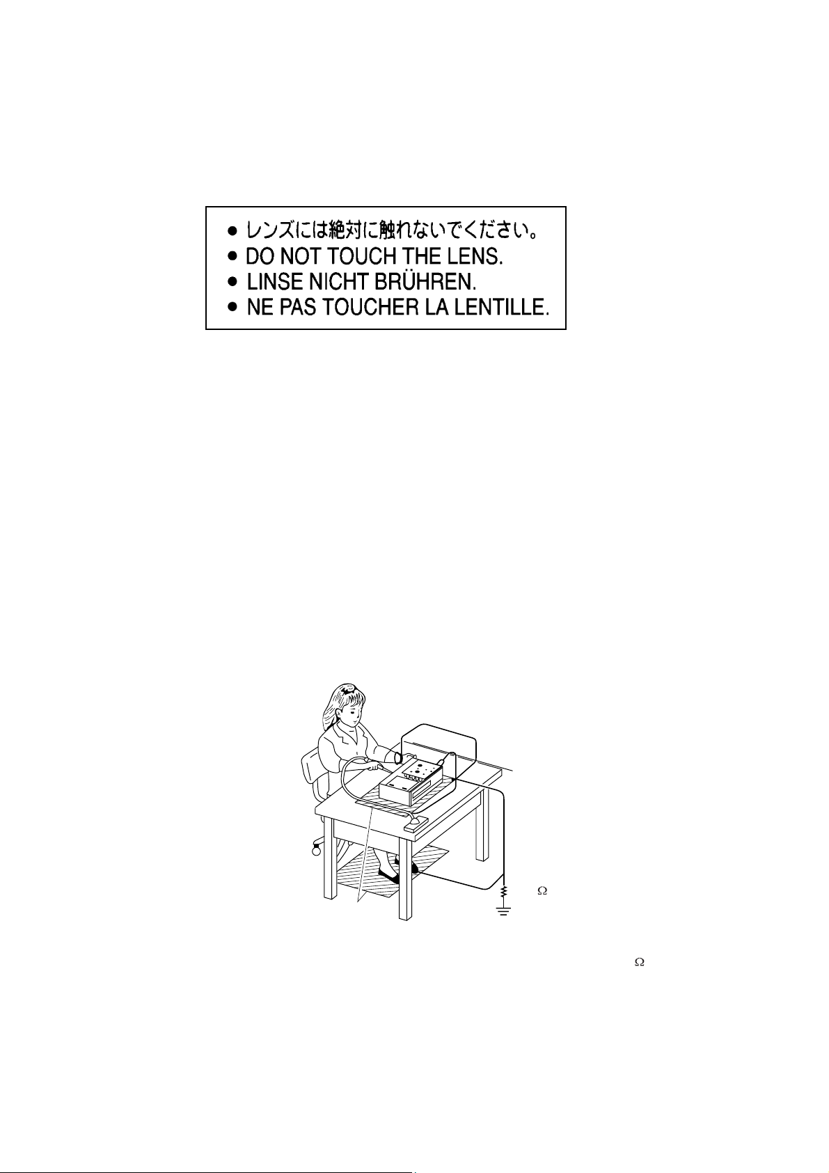
2.1 ESD PROTECTION
Whenthepowersupplyisbeingturnedon,youmaynotremovethislasercautionslabel.Ifitremoves,radiationoflaser
maybereceived.
PREPARATIONOFSERVICING
PickupHeadconsistsofalaserdiodethatisverysusceptibletoexternalstaticelectrocity.
Althoughitoperatesproperlyafterreplacement,ifitwassubjecttoelectrostaticdischargeduringreplacement,
itslifemightbeshortened.Whenreplacing,useaconductivemat,solderingironwithgroundwire,etc.to
protectthelaserdiodeformdamagebystaticelectricity.
Andalso,theLSIandICaresameasabove.
Groundconductive
wriststrapforbody.
Solderingiron
withgroundwire
orceramictype
1M
Conductivemat
Thegroundresistance
betweenthegroundline
andthegroundislessthan10
SAFTY NOTICE
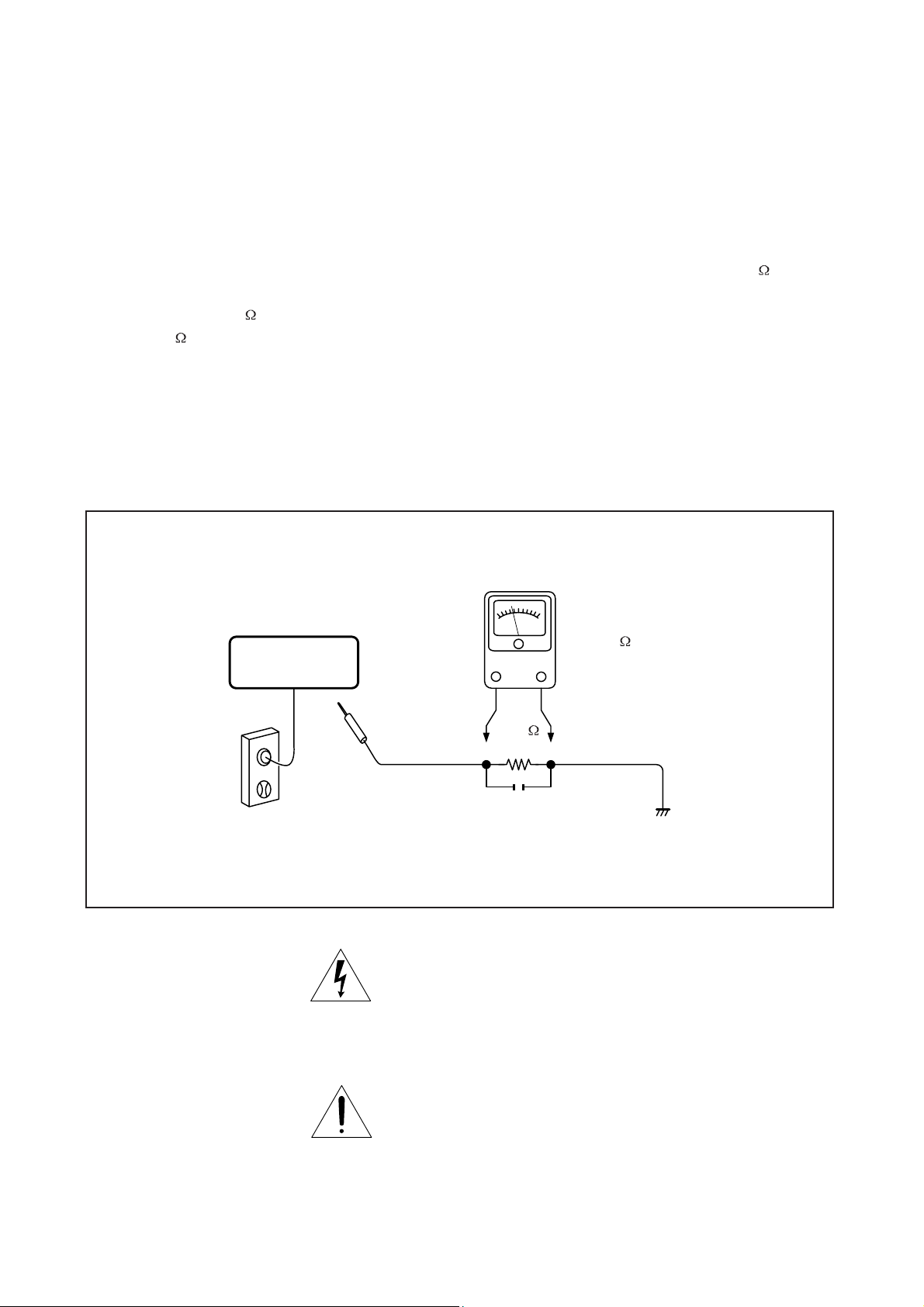
LEAKAGE CURRENT CHECK
SAFTY PRECAUTIONS
Plug the AC line cord directly into a 120V AC outlet (do
not use an isolation transformer for this check). Use an
AC voltmeter, having 5000 per volt or more sensitivity.
Connect a 1500 10W resistor,paralleled by a 0.15uF
150V AC capacitor between a knomn good earth ground
(water pipe, conduit, etc.) and all exposed metal parts of
cabinet (antennas, handle bracket, metal cabinet
screwheads, metal overlays, control shafts, etc.).
READING SHOULD NOT EXCEED 0.3V
DVD VIDEO PLAYER
Measure the AC voltage across the 1500 resistor.
The test must be conducted with the AC switch on and
then repeated with the AC switch off. The AC voltage
indicated by the meter may not exceed 0.3V.A reading
exceeding 0.3V indicates that a dangerous potential
exists, the fault must be located and corrected.
Repeat the above test with the DVD VIDEO PLAYER
power plug reversed.
NEVER RETURN A DVD VIDEO PLAYER TO THE
CUSTOMER WITHOUT TAKING NECESSARY
CORRECTIVE ACTION.
AC VOLTMETER
(5000 per volt
or more sensitivity)
Good earth ground
1500
10W
such as a water pipe,
conduit, etc.
AC OUTLET
0.15uF 150V AC
Test all exposed metal.
Voltmeter Hook-up for Leakage Current Check
The lightning flash with arrowhead symbol, within an
equilateral triangle, is intended to alert the user to the
presence of uninsulated "dangerous voltage" within the
product's enclosure that may be of sufficient magnitude to
constitute a risk of electric shock to persons.
The exclamation point within an equilateral triangle is
intended to alert the user to the presence of important
operating and maintenance (servicing) instructions in the
literature accompanying the appliance.
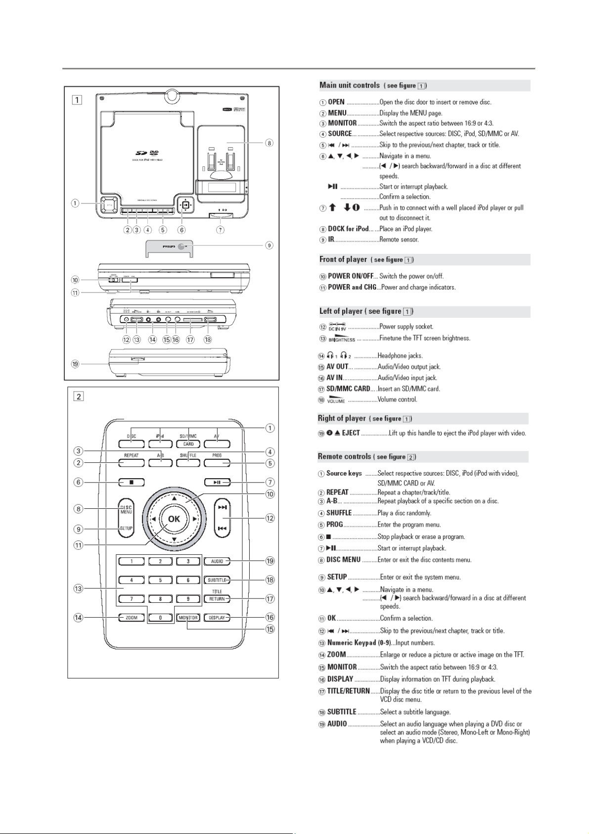
3.0 INSTRUCTION FOR USE
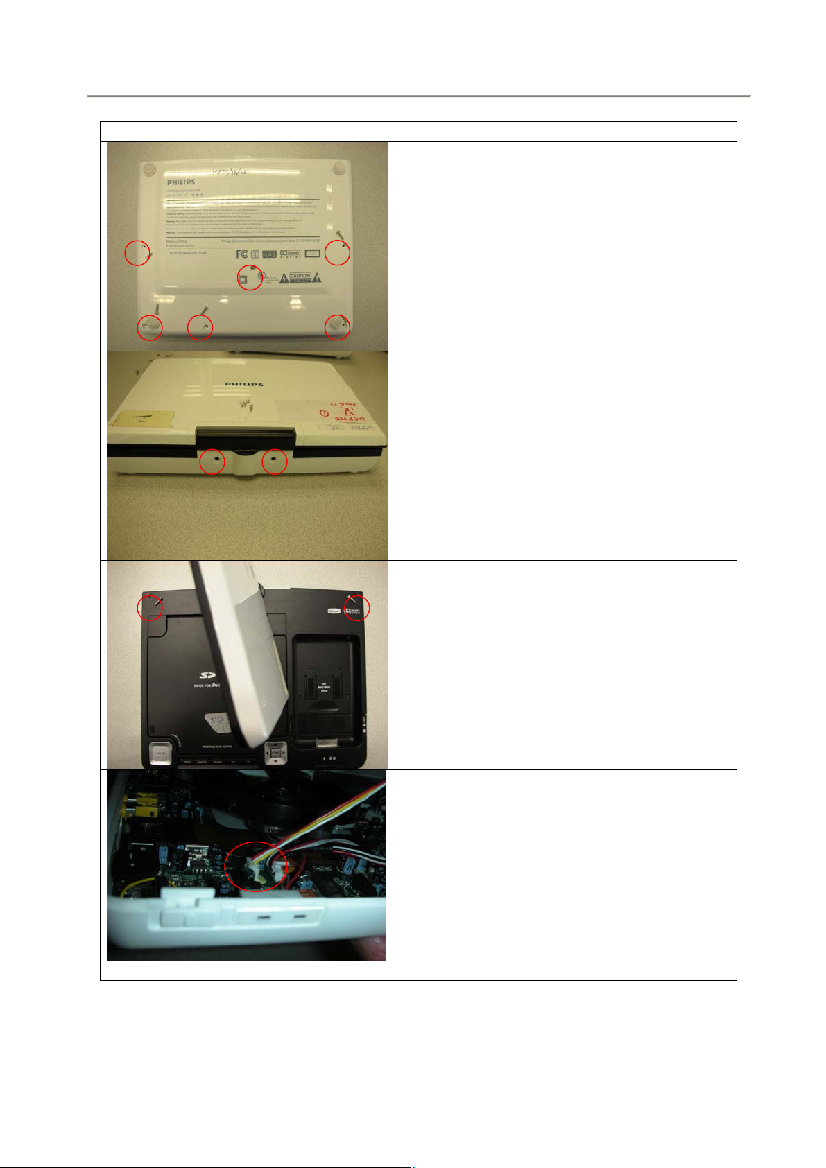
4.0 MECHANICAL INSTRUCTION
Disassembly Procedure
1 Remove 6pcs of screws on front side of
bottom cabinet.
(Please note the left hand side screw is
shorter than others, make sure do not put
long screw during re-assembly, otherwise
it will damage the middle cabinet!)
2 Remove 2pcs of screw on top side of
bottom cabinet.
3 Remove 2pcs of screws on middle cabinet.
4 Open the bottom cabinet carefully, unplug
the wire connector of key board from the
main board. (left bottom side)
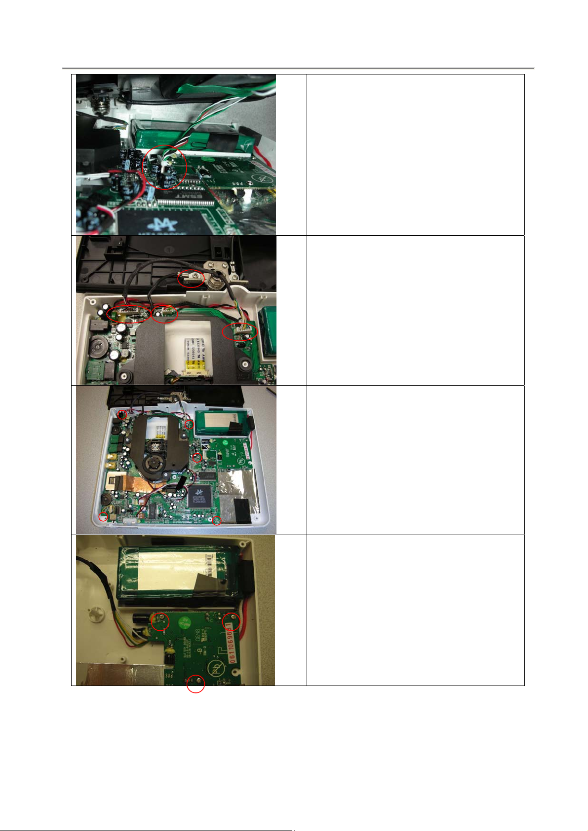
4.0 MECHANICAL INSTRUCTION
5 Unplug another wire connector of Ipod
board from main board. (right top side)
6 To remove main board from cabinet,
unplug / disconnect the wires on top side
first.
7 And then remove all screws on main board
connected with bottom cabinet.
8 To remove battery board and battery from
cabinet, remove the screws on battery
board connected with bottom cabinet first,
and then pull out the battery from taped
foam carefully. Make sure battery without
damage.
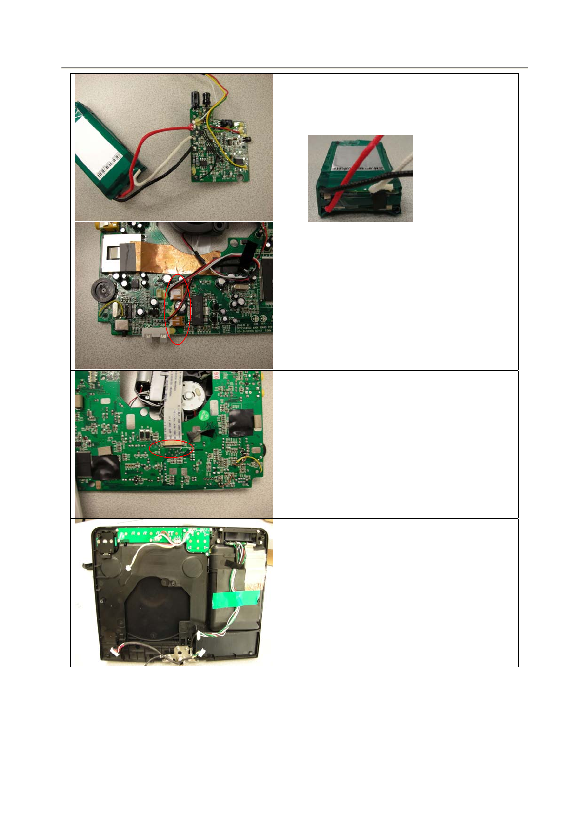
4.0 MECHANICAL INSTRUCTION
9 Be careful not to broken the wire
connection between battery and battery
board. Otherwise you can re-soldering
them as shown in picture.
10 To remove DVD loader, unplug the wires
connected with main board.
11 And then remove the flex cable on the
bottom side.
12 The middle cabinet ass’y overall
4.0 MECHANICAL INSTRUCTION
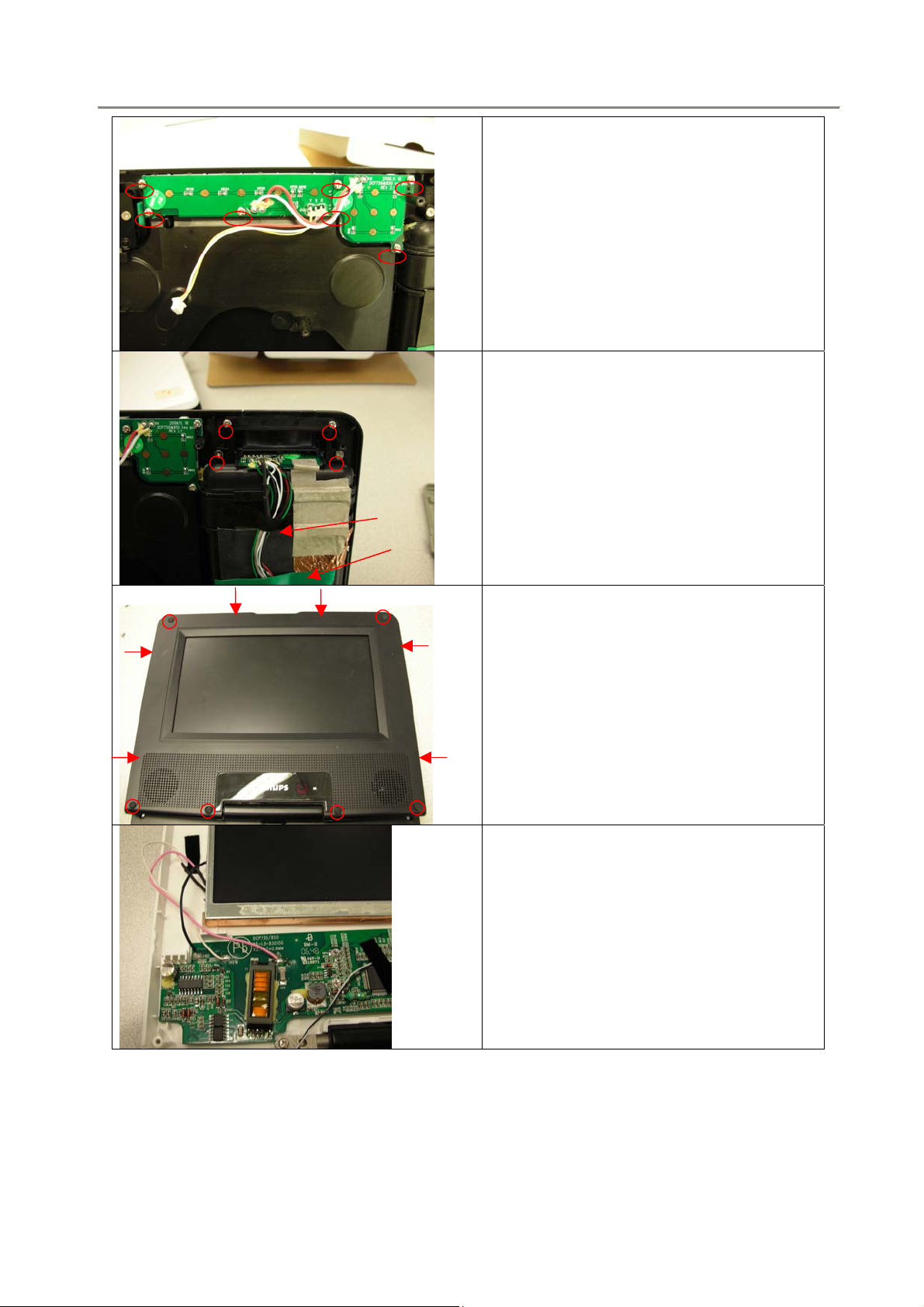
13 To remove the key board, remove the
screws as shown in picture.
14 To remove the Ipod board, remove the
screws on slider cover and then remove
some tapes attached on middle cabinet
and wires.
15 To remove front cabinet, remove the screw
on display frame first. Carefully open the
display frame with the catches by
screwdriver. (There are six catches as
shown in picture)
16 To remove the TFT, de-soldering the wire
connected between TFT and TFT board
first. (Please note the wire location as
shown in picture during re-assembly)
4.0 MECHANICAL INSTRUCTION
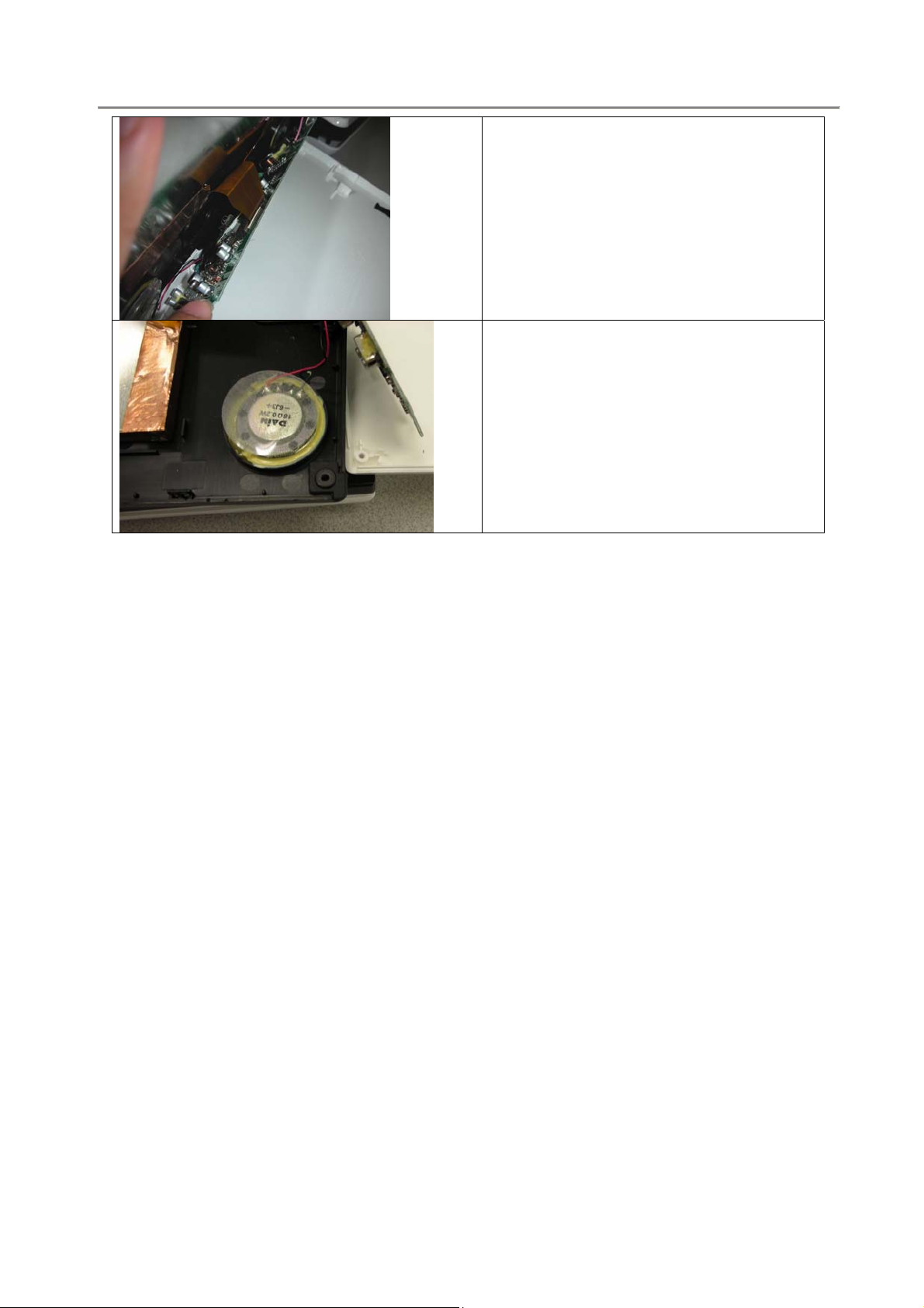
17 Unplug the flex cable connected with TFT
board at the backside also.
18 To remove the TFT board ass’y, de-
soldering the wires between speaker and
TFT board. (Black wire is connected to “ve” port and red wire is connected to “+ve”
port)
4.0 MECHANICAL INSTRUCTION
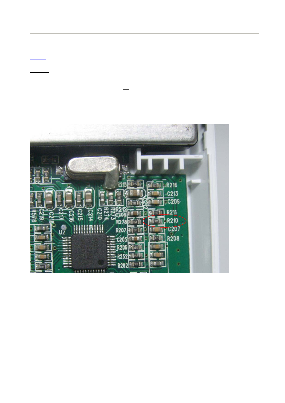
General Service Information # PI-07/011
Topic:
OEM change TFT panel from old version to new version
Details:
(996510001514) will stop production.
Change implementation from serial no. GS01
(i.e. GS01
In case to replace a new TFT panel (996510002002) on the set with serial no. GS00
also replace the 33k ohm resistor by 18k ohm resistor on the position R210 of old version TFT driver
board (996510001592) after TFT replacement.
OEM will change a new version TFT panel on DCP750/12 and the old version TFT panel
0706005421
xxxxxxxx is using new version panel and GS00xxxxxxxx is using old version panel)
xxxxxxxx, we should
Herewith the specification of R210:
RESISTOR:R210
PACKAGE: 0603
VALUE:18K
TOLERANCE:10%
Component layout diagram please refer section 8.

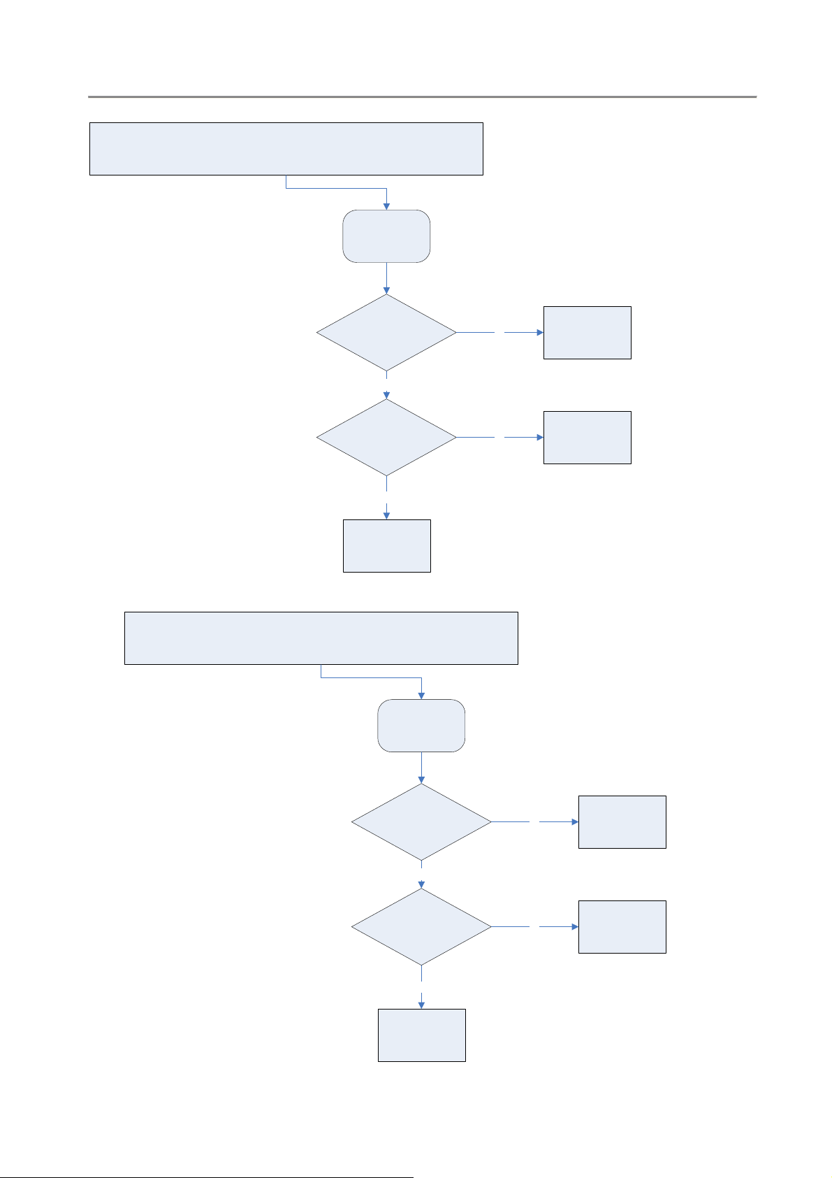
5.0 TROUBLESHOOTING
SYMPTOM: BATTERY NO POWER
BATTERY CAN'T
Power ON
Start
Check Battery capacity?
Yes
Check the Power-ON
button a nd cable OK?
NO
Replace B ut ton or
Cable
Yes
no
Chec k char gi ng
function OK?
No
Replace Main Board
Yes
No
Check adaptor
power-ON OK?
yes
SET OK?
No Defect, return
set to Customer
5.0 TROUBLESHOOTING
SYMPTOM: NO IMAGE / NO SOUND
SYMPTOM: NO IMAGE OUTPUT ( THE PANEL SHOW BLUE PICTURE)
Start
NO TE: AV Cable TYPE from outsi de to
Inside L-Audio, R-Audio, Video, Ground
SYMPTOM: NO SOUND COMES FROM SPEAKER
yes
Check the external AV
Cable TYPE
conne cti on i s O K?
Replace Main Board
yes
note
and
Start
no
no
Replace DVD DriveCheck DVD Drive work?
Exchange AV cable
Check the Connection OK? Reinsertion
yes
Check speaker OK?
yes
Replace Main Board
no
no
Change the speaker
 Loading...