

Page 1
Micro music system
DCM3100
/12
CONTENTS
Version variation and technical specification.
Service measurement setup..........................................................1-3
Service aids .................................................................................1-4
Instructions on CD playability ...............................................2-1.. 2-2
Block diagram ................................................................................3-1
Wiring diagram ..............................................................................4-1
Circuit diagram........................................................................5-1..5-7
Layout diagram .......................................................................6-1..6-7
Exploded view diagram .................................................................7-1
...................................1
©
Copyright 2012 Philips Consumer Electronics B.V. Eindhoven, The Netherlands
All rights reserved. No part of this publication may be reproduced, stored in a retrieval
system or transmitted, in any form or by any means, electronic, mechanical, photocopying,
or otherwise without the prior permission of Philips.
Published by GD 1202 Service Audio Subject to modification
Version 1.0
3141 785 37230
Page 2
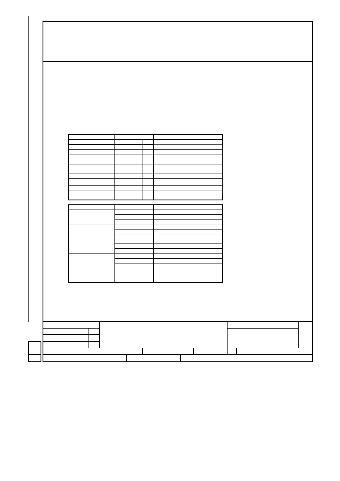
VERSION VARIATION
Type /Versions:
Board in used:
Service policy
MAIN BOARD
CD BOARD
SMPS BOARD
TUNER BOARD
CD DOOR BOARD
DISPLAY BOARD
AUX BOARD
IPOD BOARD
USB BOARD
Type /Versions:
Features
Feature diffrence
RDS
VOLTAGE SELECTOR
ECO STANDBY - DARK
* TIPS : C -- Component Lever Repair.
M -- Module Lever Repair
-- Used
DCM3100
/12
(EUROPE)
C/M
C/M
C/M
C/M
C/M
C/M
C/M
C/M
C/M
DCM3100
/12
Page 3
KT
NA
R
t
01
02
03
04
05
06
07
08
09
10
11
12
13
14
15
16
17
18
19
20
21
22
23
24
25
26
27
28
29
30
Description Pos. Descriptio n
1
2
3
4
5
6
7
8
9
10
11
12
13
14
15
Pos.
16)
17
18)
19)
20)
21)
22)
23)
24)
25)
26)
27)
28)
eproduction in whole or in part is prohibited without the
All rights are reserved.
en consent of the copyright owner.
writ
Battery location
CABINET
Dimensions with Boxes (L XXX x W XXX x H XXX): mm Material: XXX / XXX 38
Dimensions without Boxes: XXX*XXX*XXX mm ( LxWxH) Finishing: XXX 39
Weight (including packing) : XXX kg Unit in Mastercarton: N/A 40
Weight (excluding packing and batt er ies): XXXkg Units in Dealercarton: 1 set 41
INTERCONNECTION POSS I B ILITIES
Pos.
ACCESSORIES :
(1) REMOTE CO NTROL
Connection/Function Connector type Electrical data (input or R.O.P)
(3) LINE IN CABLE(2) SPEAKER BOX (X2PCS)
REMARKS :
Revise
SET SPECIFICATION
CD MICRO SYSTEM DCM3100
SHEET 17 Name: Date:2011-08-15
Check:
Tot.Sh.:
Date:
Page 4
GENERAL DESCRIPTION
V
V
A
y
W
Q and
according to
oduct
es
Q and R according to Product Division Rules
t
CD PLAYER W/PLL RADIO AUX/ IPOD DOCK
2X25W
LIFETIME(according to XUT-0026)
5 Years
PERFORMANCE CLASSES
Class Tuner Supply+Amplifier Cassette Recorder DVD/CD
Loudspeaker Boxes
IX X
II X X
III
SAFETY requirements
IEC60065
RADIATION/IMMUNITY requirements ( EMC)
CLIMATIC requirements(according to UAN-D1590)
ALL climates : +5℃ till +40 ℃
MODERATE climates :till℃
POWER SUPPLY
MAINS (AC)
ersion /12
AC Voltage 230V ± 10%
oltage Selection N
Frequenc
50 Hz
POWER CONSUMPTIO N
DCM3100
Operation (1/8 Prated,Nom AC input) 20W
Standby(Demo Mode"Off",Nom AC input) <12W
ECO Standby(No FTD Display,Nom AC input) <0.5
is prohibited without the written consent of the copyright owner.
R
Tested according to General Test Instruction UAN-D1591
Measured According to UAN-L1059 unless otherwise stated
All not mentioned data, please refer to PQR XUW-0010-JUNE 2001
Pr
Division Rul
Quality 0.4% (major) 1.5%(minor)
Reliability 2.0% (C42)
DERIVED VERSION
REMARKS
All rights are reserved. Reproduction in whole or in par
Revise
CD MICRO SYSTEM DCM3100
Name:
Check: Date:
Date:2010-08-15
APPROBATION
GENERAL SPECIFICATION
SET SPECIFICATION
7 SHEET 2Tot.Sh.:
Page 5
W
z
SUPPLY + AF AMPLIFIER + LOUDSPEAKER (BOX SPECIFI CATION)
h
Audio Signal Processing
LOUDNESS / S-BASS / PRESET EQUALIZER
Use AUX as input source with following setup conditions :
1)Input sinewave 500mV at 1kHz to L/R channel of AUX-IN socket
2)Set preset equalizer to flat mode
3)Adjust volume to get 500 m
4)The 500mW level will be used as 0dB reference.
5)Inject sine wave 500mV to AUX-in socket with frequenci es indicated in Table 1:
Table 1 (Tolerance±3dB)
DIGITAL SOUND CONTROL (DSC ) FREQUENCY RESPONSE(dB)
Loudness(dB)VOL STEP
100Hz
5
1 0 ±3
1 5 ±3
t 6 ohm load at L/R speaker outputs
10KH
±3 ±2
±2
±2
100Hz
DBB(dB)
5±3
15±3
15±3
2 5 ±3
3 2(MAX) 0
DSC Frequency(Hz) Response(dB)
Flat
out the written consent of the copyright owner.
Jazz
Pops
Rock
Classic
±2
0
100 0
1K 0
10K 0
100 3±2
1K 1±1
10K 0±3
100 8±3
1K 1±2
10K 4±1
100 8±2
1K 2±1
10K 5±2
100 3±2
1K 1±1
10K 0±1
Revise
All rig ht s ar e res e r ve d. R ep r o d u ct ion in who le o r in par t is pr o h ibited wit
CD MICRO SYSTEM DCM3100
5±3
±3
SET SPECIFICATION
Name:
Date:2010-08-15 Tot.Sh.: 7 SHEET 3
Check: Date:
Page 6
TECHNICAL DESCRIPTION
Y
V
A
A
A
A
A
A
A
A
25W
A
A
w
2X60W
GENERAL PART
'+/-3 dB
60 nW
-
es;
Support Disc
coustic Hum Noise in dB (Volume = 1): 30dB
CD-DA CD-R/RW MP3
2.5 mW - 2 dB , R Load = 32 ohm @ m ax
0dB, 1kHz CD
ipod&iphone Compatibility: iPod 5G, iPod nano 1G/2G/3G,
Classic, iPod Touch, iPhone included 3GS Iphone4 Ipad
ipod&iphone charging : 1000m
Shock sens.: >3g
At cold condition with 10%THD 1KHz
Output Stage Protection: Temperature:
INDICATORS
Power Standby Mode:
ELECTRICAL DAT
DSC: N
DBB Yes
IS: N
MAX: NA
VEC: N
FD DISPLAY W/BACK-LIGHT
Level Difference:
Tuner: FM 67.5 kHz Modulation.
CD: -6 dB track(Audio Disc 1 ,Trk 35)
Ipod&Iphone: 500mW
ux : 500mV; Rs=600Ω Headphone Out:
Input Sensitivity (±3dB)for Rated Output Power at 1KHz
Microphone Sens: N
Channel Difference: 3 dB 33dB
Hum (VOL1 to default value): 200 nW
Residual Noise (Volume Minimum) :
Channel Seperation: 40dB at 1KHz /35dB at 16KHz /30 dB at 20KHz
signal to noise ratio : 65 dB
OUTPUT POW ER(6 ohm Loading)
Mains Operation : 2 X 25W(NORMAL)
1dB(LIMIT)
(Euro & Nafta)
(Apac & Latam)
Frequency Response 100Hz ~ 16KHz within +3/-3dB (@ REF output )
ithout the written consent of the copyright owner.
LOUDSPEAKER(BOXES)
Rated Impedance : Left/Right:
Matrix: N
REMARKS
(*1) Deviations from PQR
(*2)
Electronical Parameters are to be measured at speaker terminal across
input singal in cd mode setting in DBB Off unless specified otherwise.
6Ω @ 100 Hz ~ 15kHz
ohm load with
SET SPECIFICATIONRevise
All rig ht s ar e res e r ve d. R ep r o d u ct ion in who le o r in par t is pr o h ibited
CD MICRO SYSTEM DCM3100
Name: 7 SHEET 4Date:2010-08-15 Tot.Sh.:
Check: Date:
Page 7
A
A
A
A
A
A
A
A
A
A
y
fN/A
AN/A
fN/A
AdBfN/A
y
A
A
f
A
A
A
)
A
f
55
50
N/A
FM S/N Ratio(A weighted) Mono input 68d
55
50
A
y
A
28
20
y
f
f
f
dB
t
TECHNICAL DESCRIPTION
GENERAL PART
FM 87.5--108MHz MHz
MN/
ERIAL
FM : 75ohm ANTENNA
INDICATIORS
ELECTRICAL DAT
he written consent of the copyright owner.
DVD MINI SYSTEM
WAVE Range(-/21) TOLERANCE
:
N/
N/
N/
N/
N/
N/
N/
N/
N/
N/
N/
N/
N/
VFD
Limit Unit FM
-3dB Limiting Point :
Distortion(RF 1 mV, Freq.Dev. 75kHz) :
26dB Quieting Sensitiv t
Crosstalk (RF 1mV Freq. Dev.40kHz) :
Search time 24~30 19~35 dB
St Turn-on Point Ratio/ Q uad Det ect or s : N
Search Tuning Sensitivi t
Modulation Hum :
8th, 9th, 10th Harmonics Whistle :
Overall Frequency Response(63~12.5kHz
FM 46dB Quiying sensitivit y (Ster eo)
FM Adjacent Channel selectivit
FM Image Rejection
FM Channel Seperantion 1K
mplification Reserve(*1) :
M Suppression I/P: 48~82dB
:
Nom
17
0
2
18
30
30
55
40
0
45
20
30
limit unit
23.5
3
22
26
≦60
---
25
45
35
±3 dB
50
25 dB
20
dB
%
dB
dB
Sec
dB
dB
dB
db
dB *
dB
Wave Range SENS Rejection Handling S9/300kHz
FM Nom. 18 116 dB
REMARKS
Lim. 22 108 dB
Units. dB
μV/m
Image IF Rejection Large Signal Selectivit
24 55
20
dB dB mV/m dB
50
24
20
Revise SET SPECIFICATION
All rig ht s ar e res e r ve d. R ep r o d u ct ion in who le o r in par t is pr o h ibited witho u t
Name: Date:2010-08-15
CD MICRO SYSTEM DCM3100
Tot.Sh.:
7 SHEET 5
Check: Date:
Page 8
Description External DAC
G
A
A
CD MECH:
Channel Unbalance <±2dB ( Vol 0 ~ -50dB )
Frequency Response(+0.5/-1.0dB) 20Hz~20kHz
Signal to Noise Ratio(A-weighted) 70dBA(Lim 65 dBA)
THD Noise(20 ~20,000Hz) 0.5%(Lim 2%)
Outband Attentuation 35dB
Channel Separation 1K 40dB (Lim.30dB)
Emphasls(switched automatically by CD 10) 15 / 50μs
DA11VF
(1kHz) 0.1% at -20dBFS
16K 35dB(Lim.25dB)
20K 30dB(Lim.25dB)
Sanyo
Mp3 performance
Bit rates 32K-320Kps
Sampling rates(MPEG-1 Layer 3) 32kHz/44.1KHZ/48kHz
Joliet (8 character OSD display)
Windows XP
UDF basic (close format)
Mp3 multisession Directory resting Max 8 level, Max directory 32
Display filename/ID3
255 folders/999songs
ipod&iphone performance
Channel balance Limit: 2dB
singnal to noise ratio(unweighted) Limit:60dB
Channel seperation Limit:45dB
Max.volume noise(Bass off) Limit:3mV
Max.volume noise(Bass off) Limit:1mV
ipod&iphone Compatibility: iPod 5G, iPod nano 1G / 2G / 3G, iPodClassic, iPod Touch, iPhone&3
ipod&iphone charging : 1000m
ipad charging : 2100m
description
description
Revise
All rig ht s ar e res e r ve d. R ep r o d u ct ion in who le o r in par t is pr o h ibited witho u t th e wr it t e n
CD MICRO SYSTEM DCM3100
Name: Date:2010-08-15
Check: Date:
DVD PART
SET SPECIFICATION
SHEET 6Tot.Sh.: 7
Page 9
TECHNICAL SPECIFICATION
y
y
V
p
GENERAL PART
Tmie Setting : Clock and Timer
Timer W akeup M ode : CD / Tuner/Aux (Depend on power off source)
Remarks Time Setting : 24 Hrs
Wake Up Volume Co ntrol : No
Volume at Wakeup : NC
No of Timer Settings : 1
Clock Accurac
RC operating distance :
INDICATORS
Display Type : VFD
: Lim. +/- 2 sec / da
REMARKS
roduction in whole or in part is prohibited without the written consent of the copyright owner.
ERSION OVERVIEW
Tape PART SPECIFICATION
Revise
All rights are reserved. Re
CD MICRO SYSTEM DCM3100
Name: Date:2011-08-15 Tot.Sh.: 7 SHEET 7
Check: Date:
SET SPECIFICATION
Page 10
e
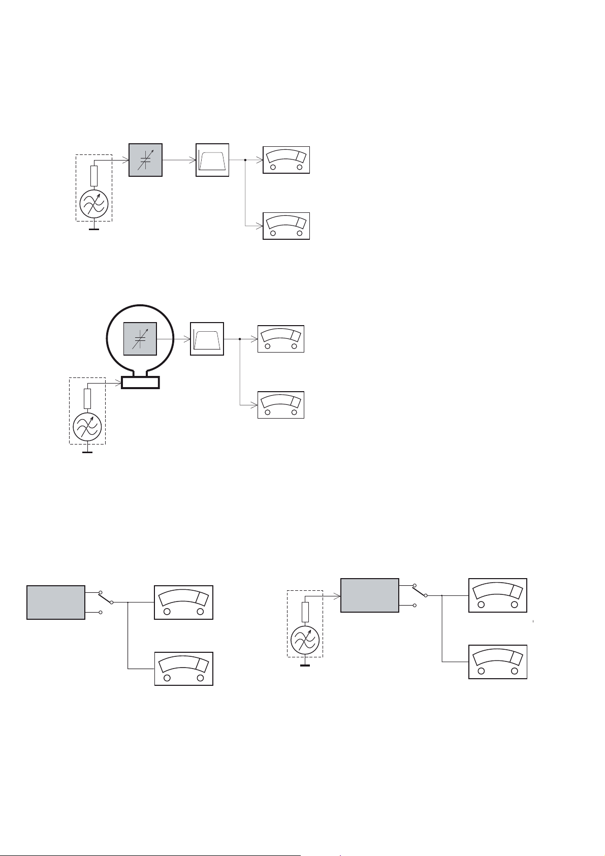
MEASUREMENT SETUP
Tuner FM
1-3
Bandpass
LF Voltmeter
e.g. PM2534
RF Generator
e.g. PM5326
DUT
250Hz-15kHz
e.g. 7122 707 48001
Ri=50:
S/N and distortion meter
e.g. Sound Technology ST1700B
Use a bandpass filter to eliminate hum (50Hz, 100Hz) and disturbance from the pilottone (19kHz, 38kHz).
Tuner AM (MW,LW)
RF Generator
e.g. PM5326
Ri=50:
DUT
Frame aerial
e.g. 7122 707 89001
Bandpass
250Hz-15kHz
e.g. 7122 707 48001
LF Voltmeter
e.g. PM2534
S/N and distortion meter
e.g. Sound Technology ST1700B
To avoid atmospheric interference all AM-measurements have to be carried out in a Faraday´s cage.
Use a bandpass filter (or at least a high pass filter with 250Hz) to eliminate hum (50Hz, 100Hz).
CD
Use Audio Signal Disc
(replaces test disc 3)
DUT
L
R
SBC429 4822 397 30184
S/N and distortion meter
e.g. Sound Technology ST1700B
LEVEL METER
e.g. Sennheiser UPM550
-
Recorder
Use Universal Test Cassette CrO2 SBC419 4822 397 30069
or Universal Test Cassette
LF Generator
e.g. PM5110
Fe SBC420 4822 397 30071
DUT
L
R
S/N and distortion met
e.g. Sound Technology ST170
LEVEL METER
e.g. Sennheiser UPM550
with FF-filter
Page 11
SERVICE AIDS
1-4
GB
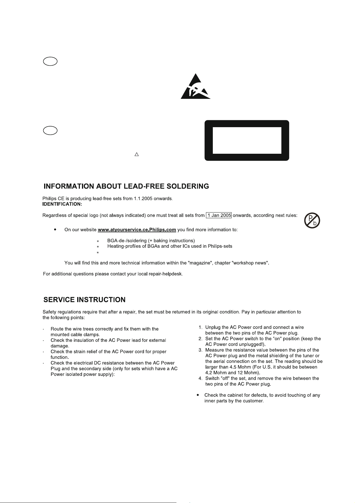
All ICs and many other semi-conductors are
susceptible to electrostatic discharges (ESD).
Careless handling during repair can reduce life
drastically.
When repairing, make sure that you are
connected with the same potential as the mass
of the set via a wrist wrap with resistance.
Keep components and tools also at this
potential.
WARNING
GB
Safety regulations require that the set be restored to its original
condition and that parts which are identical with those specified,
be used
Safety components are marked by the symbol
!
.
ESD
CLASS 1
LASER PRODUCT
Lead free
Page 12

INSTRUCTIONS ON CD PLAYABILITY
Customer complaint
"CD related problem"
Set remains closed!
check playability
1
2 - 1
playability
ok ?
Y
Play a CD
for at least 10 minutes
check playability
playability
ok ?
Y
N
"fast" lens cleaning
check playability
playability
ok ?
N
3
N
Y
For flap loaders (= access to CD drive possible)
cleaning method
4 is recommended
add Info for customer
"SET OK"
2
return set
1 - 4 For description - see following pages
Exchange CDM
Page 13

INSTRUCTIONS ON CD PLAYABILITY
2 - 2
1
PLAYABILITY CHECK
For sets which are compatible with CD-RW discs
use CD-RW Printed Audio Disc....................7104 099 96611
TR 3 (Fingerprint)
TR 8 (600µ Black dot) maximum at 01:00
• playback of these two tracks without audible disturbance
playing time for: Fingerprint
Black dot from 00:50 to 01:10
• jump forward/backward (search) within a reasonable time
For all other sets
use CD-DA SBC 444A..................................4822 397 30245
TR 14 (600µ Black dot) maximum at 01:15
TR 19 (Fingerprint)
TR 10 (1000µ wedge)
• playback of all these tracks without audible disturbance
playing time for: 1000µwedge 10seconds
Fingerprint 10seconds
Black dot from 01:05 to 01:25
• jump forward/backward (search) within a reasonable time
10seconds
4
LIQUID LENS CLEANING
Before touching the lens it is advised to clean the
surface of the lens by blowing clean air over it.
This to avoid that little particles make scratches on
the lens.
Because the material of the lens is synthetic and coated
with a special anti-reflectivity layer, cleaning must be done
with a non-aggressive cleaning fluid. It is advised to use
“Cleaning Solvent
The actuator is a very precise mechanical component and
may not be damaged in order to guarantee its full function.
Clean the lens gently (don’t press too hard) with a soft and
clean cotton bud moistened with the special lens cleaner.
The direction of cleaning must be in the way as indicated in
the picture below.
2
CUSTOMER INFORMATION
It is proposed to add an addendum sheet to the set which
informs the customer that the set has been checked
carefully - but no fault was found.
The problem was obviously caused by a scratched, dirty or
copy-protected CD. In case problems remain, the customer
is requested to contact the workshop directly.
The lens cleaning (method 3) should be mentioned in the
addendum sheet.
The final wording in national language aswell as the printing
is under responsibility of the Regional Service Organizations.
Page 14

BLOCK DIAGRAM
3 -1
3 - 1
Page 15

WIRING DIAGRAM
4 -1
4 - 1
Page 16

CIRCUIT DIAGRAM-MAIN BOARD
PART 1
RB
RB
L14
AUX-L
L14
FB
FB
332
332
C188
C188
R53
R53
RB
RB
L24
L24
FB
FB
R57
R57
RB
RB
L32
L32
FB
FB
L12FBL12
FB
L15FBL15
332
332
C185
C185
MAIN BD.
AUX-R
AUX-GND
TAPE-L
TAPE-R
LINK-R
LINK-L
AUX-GND
R74
R74
1K5
1K5
C14NCC14
NC
R64
R64
4k7
4k7
R66
R66
4K7
4K7
C11NCC11
NC
1K5
1K5
R540RR54
0R
100PF
100PF
47P
47P
C182
C182
C181
C181
C12NCC12
NC
1K5
1K5
R610RR61
0R
47P
47P
C179
C179
C180
C180
100PF
100PF
C13NCC13
R69
R69
FB
IPOD_DOCKING
IPOD_DOCKING
5 -1
C51
1k
R711kR71
NC
R65NCR65
NC
R67NCR67
1k
R601kR60
1k
R621kR62
NC
1K5
1K5
47P
47P
C187
C187
C51
2.2uF
2.2uF
47P
47P
C192
C192
C461
C461
2.2uF
2.2uF
102
102
C189
C189
C459
C459
2.2uF
2.2uF
102
102
C190
C190
C465
C465
2.2uF
2.2uF
C183100PC183100P
C464
C464
2.2uF
2.2uF
C184
C184
100P
100P
1k
R681kR68
+8VCC
C475
C475
2.2uF
2.2uF
4052_A
4052_B
V476
V476
2.2uF
2.2uF
R59
R59
10K
10K
R58
R58
10K
10K
R5420RR542
0R
10K
10K
C165 102C165 102
R51
R51
R5410RR541
0R
10K
10K
102
102
R55
R55
C166
C166
1K
R161KR16
C527
C527
+
+
100uF/16V
100uF/16V
C16
C16
2.2uF
2.2uF
100K
100K
R46
R46
100K
100K
R34
R34
IC501
IC501
TC-4052BP
TC-4052BP
1K
0.1u
0.1u
C27
C27
R211KR21
+8VCC
+
+
0.1u
0.1u
C519
C519
R513
R513
15K
15K
NC
C507NCC507
R515
R515
NC
C513NCC513
C575
C575
C521
C521
2.2uF
2.2uF
15K
15K
102
102
C508
C508
R514
R514
C523
C523
15K
15K
2.2uF
2.2uF
15K
15K
R516
R516
C517 102C517 102
2.2u
2.2u
100uF/16V
100uF/16V
C520
C520
C524
C524
C525
C525
0.22u
0.22u
0.022u
0.022u
D2761
D2761
IC510
IC510
C522
C522
2.2u
2.2u
8K2
8K2
R536
R536
MIX-R
MIX-L
AUX BD.
CN505CN505
CN704CN704
CN710CN710
R5750RR575
0R
R5730RR573
0R
220P
220P
220P
220P
100K
100K
100K
C549
C549
C548
C548
D-
D+
L710
L710
L712
L712
100K
R576
R576
R574
R574
C760
C760
0.1uF
0.1uF
C780
C780
E-CAP_100_16#1
E-CAP_100_16#1
FB 10T
FB 10T
0.1uF
0.1uF
C764
C764
FB 10T
FB 10T
C5471UC547
U-GND
1U
1U
USB+5V
L507
L507
L504
L504
L505
L505
L506
L506
FB 10T
FB 10T
L502
L502
FB 10T
FB 10T
L503
L503
FB 10T
FB 10T
C546
C546
FB 10T
FB 10T
FB 10T
FB 10T
FB 10T
FB 10T
FB 10T
FB 10T
L501
L501
C5501UC550
223
223
USB+5V
C545
C545
U-GND
5 - 1
223
223
223
223
223
223
C572
C572
C573
C573
L761FBL761
D-
L760FBL760
D+
JK301JK301
LINK
JK302JK302
JK601JK601
USB-JACK
FB
FB
IPOD BD.
USB BD.
IP1
IP1
549K 1%
549K 1%
49.9K 1%
49.9K 1%
34.2K 1%
34.2K 1%
75K 1%
75K 1%
R353
L100 FBL100 FB
R348 49.9K 1%R348 49.9K 1%
R353
R344
R344
R346
R346
R345
R345
C250
C250
104
104
D
D
ME2302
ME2302
Q52
Q52
S
S
1N4148
1N4148
L99FBL99
FB
L97 FBL97 FB
FB
L96FBL96
Q54
Q54
8050
8050
47K
100K
100K
R350
R350
D201
D201
1N4148
1N4148
47K
R356
R356
R355
R355
47K
47K
R3471KR347
1K
Q53
Q53
8050
8050
R349
R349
100K
100K
G
G
R352
R352
10K
10K
D38
D38
CN202CN202
CN201CN201
CN104CN104
CN311CN311
IPOD+5V
IPOD_IO
IPOD_DET13
IPOD_DET30
IPOD_RX
IPOD_TX
C156
C156
102P
102P
R104 100RR104 100R
R10 100RR10 100R
C157
C157
102P
102P
R36 22KR36 22K
47P
10uF
10uF
10uF
10uF
104
104
10K
10K
47P
FC6 104PFC6 104P
C154
C154
R147
R147
R151
R151
R12 10KR12 10K
C142
C142
C147
C147
R704
R704
10K
10K
R37
R37
22K
22K
10K
10K
10K
10K
47P
47P
47P
47P
10K
10K
C148
C148
100pF
100pF
R711
R711
C134
C134
47P
47P
EC8
EC8
22uF/16V
22uF/16V
TC5
TC5
TC6 10uFTC6 10uF
TC8
TC8
820P
820P
820P
820P
C141
C141
C152
C152
C151
C151
R11
R11
IC305
IC305
4558
4558
C158
C158
C138
C138
TC701
TC701
47uF16V
47P
47P
+
+
-
-
-
-
+
+
100pF
100pF
C149
C149
47uF16V
104
104
C140
C140
2U2
2U2
C161
C161
2U2
2U2
47P
47P
47P
47P
C163
C163
47P
47P
R722 10KR722 10K
C153
C153
C150
C150
L3
FC11
FC11
104
104
R132
R132
R131
R131
C162
C162
47P
47P
56NHL356NH
VCC+9V
3k3
3k3
3k3
3k3
47p
47p
C169
C169
IPOD-R
IPOD-L
1k
C170 47pC 170 47p
R723 1kR723 1k
R1331kR133
Page 17

CIRCUIT DIAGRAM-MAIN BOARD
PART 2
5 -2
5 - 2
REC_RCH
REC_LCH
IIC_SDA1
IIC_SCL1
MIX-R
MIX-L
CD_R
CD_L
IPOD-R
IPOD-L
TU-R
FM-ANT
TU-L
VCC+9V
PH-R
PH-L
PH-EN
PLL_CS
R407
R407
R408
R408
C467
C467
C468
C468
C438
C438
C443
C443
R458
R458
1uF
1uF
C49
C49
1uF
1uF
C50
C50
R4061KR406
1K
R4051KR405
1K
C437
C437
R41kR4
2.2uF
2.2uF
1k
C436
C436
R11kR1
2.2uF
2.2uF
1k
R14
R14
R7
22k
22k
22kR722k
C448
Q404
Q404
9014
9014
C448
2.2uF
2.2uF
C446
C446
2.2uF
2.2uF
30P
30P
30P
30P
30P
30P
30P
30P
30P
30P
30P
30P
30P
30P
30P
30P
2K
100P
100P
2K
100P
100P
C30
C30
C35
C35
C31
C31
C37
C37
C32
C32
C25
C25
C33
C33
C24
C24
C431
C431
R4102KR410
C432
C432
R4092KR409
VCC+9V
R40147R401
R460
R460
47
20K
20K
Q408
R4591KR459
1K
30P
30P
D103D103
FB500R
FB500R
Q408
8550
8550
C109
C109
30P
30P
NC
L108NCL108
C105
C105
X101
X101
32.768KHZ
32.768KHZ
22P
22P
IC101
IC101
Si7405
Si7405
R1061KR106
1K
FB201FBFB201
BC206
BC206
BC207
BC207
FB202FBFB202
30P
30P
C38
C38
FB
22P
22P
22P
22P
FB
R21147R211
47
C104
C104
22P
22P
4K7
4K7
4K7
4K7
2.2uF
2.2uF
2.2uF
2.2uF
2.2uF
2.2uF
2.2uF
2.2uF
R28
R28
4.7K
4.7K
22K
22K
C110
C110
L105
L105
C23
C23
C22
C22
C429
C429
C428
C428
220uF/10V
220uF/10V
0.1UF
0.1UF
C401
C401
C403
C403
220uF/6.3V
220uF/6.3V
BC203
BC203
0.1UF
0.1UF
CE202
CE202
220uF/6.3V
220uF/6.3V
R110
R110
CE201
CE201
100
100
30P
30P
30P
30P
100P
100P
100P
100P
RCH 4
RCH 4
LCH 4
LCH 4
RCH 3
RCH 3
LCH 3
LCH 3
RCH 2
RCH 2
LCH 2
LCH 2
RCH 1
RCH 1
LCH 1
LCH 1
0.1UF
0.1UF
C457
C457
BC202
BC202
22P
22P
R207
R207
10K
10K
FB204
FB204
FB300
FB300
100
100
C113
C113
R108
R108
C454
C454
C202
C202
220P
220P
SCL
SCL
SDA
SDA
DGND
DGND
VDD
CREF
VDD
CREF
GND
GND
30P
30P
30P
30P
30P
30P
22uF/16V
22uF/16V
C26
C26
C29
C29
C28
C28
C434
C434
R202
R202
68K
68K
CE204
CE204
ETK4800
ETK4800
220uF/10V
220uF/10V
C203
C203
220P
220P
C102
C102
R102
R102
10R
10R
68P
68P
C435
C435
30P
30P
IC303
IC303
C101
C101
22P
22P
1uF
1uF
IC401
IC401
SC7314
SC7314
C201
C201
2.2UF
2.2UF
104P
104P
R403
R403
5.6K
5.6K
820P
820P
474
474
0.1UF
0.1UF
0.1UF
0.1UF
C423
C423
C422
C422
C404
C404
C417
C417
IN(L)
IN(L)
BIN(L)
BIN(L)
OUT(L)
OUT(L)
BOUT(L)
BOUT(L)
LOUD(L)
LOUD(L)
TREBLE(L)
TREBLE(L)
OUT L
OUT L
OUT R
OUT R
IN(R)
IN(R)
BIN(R)
BIN(R)
TREBLE(R)
OUT(R)
OUT(R)
2.2uF
2.2uF
C430
C430
R203
R203
68K
68K
ZD201
ZD201
5.6V
5.6V
C120
C120
TREBLE(R)
BOUT(R)
BOUT(R)
LOUD(R)
LOUD(R)
C15
C15
C17
C17
C36
C36
474
474
C424
C424
0.1UF
0.1UF
C425
C425
R517
R517
0.1UF
0.1UF
C411
C411
R209NCR209
R213
R213
2.2K
2.2K
10K
10K
R208
R208
BC201
BC201
0.1UF
0.1UF
C204
C204
R214
R214
2.2K
2.2K
2.2UF
2.2UF
C1151UC115
1U
C1141UC114
1U
102
102
102
102
C116
C116
C117
C117
10K
10K
C106
C106
104P
104P
100uF/16V
100uF/16V
R111
R111
C439
C439
C407
C407
820P
820P
NC
C427
C427
30P
30P
AGND
30P
30P
C34
C34
30P
30P
C18
C18
30P
30P
C21
C21
30P
30P
30P
30P
C426
C426
30P
30P
30P
30P
30P
30P
5.6K
5.6K
47uF/25V
47uF/25V
Q202NCQ202
NC
CE203
CE203
100uF/6.3V
100uF/6.3V
R210NCR210
NC
R216NCR216
NC
Q201NCQ201
NC
C53NCC53
NC
R126
R126
3K3
3K3
R123
R123
3K3
3K3
C52NCC52
NC
100P
100P
7K5
7K5
C54
C54
R41
R41
10K
10K
L103FBL103
FB
L106FBL106
R112
R112
FB
68P
68P
C707
C707
1K
R4271KR427
R4211KR421
1K
R4221KR422
1K
C509
C509
100PF
100PF
R13
R13
47K
47K
C515
C515
R9
100PF
100PF
47KR947K
R4251KR425
1K
C541
C541
C456
C456
47PF
47PF
0.1UF
0.1UF
C463
C463
R201
R201
22k
C1191UC119
C1181UC118
22k
PH_MUTE
R204
R204
22k
22k
PH_MUTE
L101FBL101
1U
FB
L102FBL102
1U
FB
220
220
IIC_SDA
220
220
IIC_SCL
R215NCR215
NC
100P
100P
7K5
7K5
R42
R42
C55
C55
R715
R715
R717
R717
68P
68P
C719
C719
C514
C514
1UF
1UF
MN\62429
MN\62429
IC403
IC403
ZD502
ZD502
6.2V
6.2V
Q101 S8050Q101 S8050
C108
C108
62429-CLK
62429-TADA
C57
EQ_ROUT
IPOD+5V
R189
R189
15k
15k
C59
C510
C510
1UF
1UF
C518
C518
1UF
1UF
C516
C516
1UF
1UF
VCC+9V
R239
R239
470
470
R80RR8
0R
R60RR6
0R
TU-R
TU-L
R424
R424
4R7
4R7
560
560
R109
R109
4V3
4V3
0.1uF
0.1uF
47/16
47/16
C107
C107
ZD101
ZD101
C59
R4511KR451
102
102
1K
R4531KR453
1K
CDMUTE
A-MUTE
C419
C419
100uF/16V
100uF/16V
NC
47P
47P
R452
R452
R191NCR191
EQ_LOUT
R174
R174
15k
15k
C60
C60
102
102
NC
47P
47P
R454
R454
R192NCR192
R532
R532
22K
22K
FB1FBFB1
FB
VCC+9V
0.1uF
0.1uF
C413
C413
MAIN-R
47P
47P
C538
C538
MAIN-L
47P
47P
C542
C542
D403NCD403
NC
1N4148
1N4148
D502
D502
A-MUTE
LINK-R
AUX-GND
LINK-L
HP-ET
P-MUTE
PH-L
PH-R
0.1uF
0.1uF
47P
47P
BC2
BC2
C19
C19
EC22
EC22
220U/10V
220U/10V
C10 104C10 104
GND
CN306CN306
L1
33UHL133UH
C4 103C4 103
R73
R73
5.6K
5.6K
C9 22UF/16VC9 22UF/16V
R30
R30
R72
R72
3.9K
3.9K
1K8
1K8
VCC+9V
ZD1 8V2ZD1 8V2
+22V
+9V
+5V
C8
332C8332
R29
R29
R3256R32
56
R3356R33
56
220uF/10V
220uF/10V
C39
C39
PWR-EN
C450
C450
C447
C447
470uF/16V
470uF/16V
470uF/16V
470uF/16V
C57
470UF/25V
470UF/25V
C7
C7
L4
R23
R23
2K2
2K2
Q403
Q403
A8550
A8550
R411
R411
47K
BC1
BC1
FB/AIL2FB/AI
47K
0.1uF
0.1uF
Q411
Q411
S9014
S9014
1.5K
1.5K
R416
R416
R414
R414
L311
L311
FB/AI
FB/AI
NC
CE1NCCE1
L2
100PC7100P
104C7104
33UHL433UH
100K
100K
IC402
IC402
TG1484
TG1484
1.5K
1.5K
CN402CN402
C7NCC7
NC
R412
R412
+22V
+22V
GND
GND
+12V
+5V
PWR-EN
+22V
470UF/25VC5470UF/25V
1UFC71UF
47PC747P
C7
C7
C5
+9V
PWR-EN
10K
10K
47K
47K
R413
R413
Page 18

CIRCUIT DIAGRAM-MAIN BOARD
PART 3
D7NCD7
NC
NC
IP-AUDIO_DET
VCC+9V
AUDIO_DET
REC_RCH
REC_LCH
IP-R
IP-L
D8NCD8
R47 100R47 100
22K
C71 470KC71 470K
C63 225C63 225
100p
100p
C64
C64
C65
C65
22K
R48
R48
560K
560K
R31
R31
225
225
68K
68K
68K
68K
22uF/16V
22uF/16V
103
103
C74
C74
C69
C69
IN4148
IN4148
IN4148D9IN4148
D9
D10
D10
R70
R70
R63
R63
5 -3
R708
R708
100R
VFD_STB
VFD_CLK
VFD_DAT
VOL+
VOLBASS+
BASS-
VCC-MCU
R727
R727
10K
10K
TRERLE+
TRERLE
PH-EN
CD_EN
USB_ON
REC_SYS
HP-ET
PLL_CS
IIC_SDA
IIC_SCL
VCC-MCU
10K10K
10K10K
C708
C708
104P
104P
C70
C70
22uF/16V
22uF/16V
IC1
IC1
22K
22K
R49
R49
-
-
4558
4558
+
+
C73 100pC73 100p
+
+
C709
C709
104P
104P
-
-
OP_SW
CL_SW
100p
100p
C66
C66
100k
100k
R75
R75
R76 100kR76 100k
62429_SCL
62429_SDA
IPOD_CON
225
225
C68
C68
DET30
DET13
IP_RX
IP_TX
C67 225C67 225
200K
200K
R45
R45
R7511KR751
R7521KR752
C72 470KC72 470K
C75 103C75 103
MPOWER
R738 330RR738 330R
R741 330RR741 330R
R742
R742
330R
330R
R743
R743
330R
330R
R7301KR730
1K
R7101KR710
1K
R747
R747
330R
330R
R533
R533
10k
10k
330R
330R
R714
R714
68P
68P
C718
C718
VCC-MCU
TAPE_DET
PC_RESET
VDD3_3D
Q703
Q703
8050
8050
R776
R776
PC_SDA
C731 100PC731 100P
C732 100PC732 100P
PC_RESET
4K7
4K7
PWR_EN
105P
105P
C741
C741
R768
R768
10K
10K
R7781KR778
1K
1K
1K
VCC-MCU
R711 100PR711 100P
R732 100PR732 100P
R733 330RR733 330R
R734 330RR734 330R
R735 330RR735 330R
R736 330RR736 330R
R22
R22
100k
100k
C735 100PC735 100P
C734 100PC734 100P
C733 100PC733 100P
VDD3_3D
VDD3V3A
FB701FBFB701
FB702FBFB702
FB703FBFB703
FB704FBFB704
FB705FBFB705
100R
R7731KR773
C739
C739
102P
102P
USB_ON
CL_SW
OP_SW
R769
R769
100K
100K
AGND
CD_EN
4052-A
CD-L
CD_R
RX
TX
+5V
TRERLE+
VFD_DAT
VFD_CLK
VFD_STB
TRERLE
BASSBASS+
VOL+
VOL-
IR
R35
R35
10K
10K
R39
R39
10K
10K
L28 FBL28 FB
L27 0RL27 0R
L26 FBL26 FB
4052-B
AUDIO_DET
IP-AUDIO_DET
4052-A
CA6817
CA6817
100P
100P
100P
100P
C742
C742
104P
104P
47UF/16V
47UF/16V
IC702
IC702
330R
330R
330R
330R
10K
10K
VCC-MCU
R770
R770
100K
100K
VCC-MCU
MPOWER
C747
C747
R7451KR745
R15 330R15 330
CD_TX
CD_RX
R771
R771
100K
100K
R7721KR772
R7741KR774
47UF/16V
47UF/16V
L703FBL703
FB
IIC_SCL
IIC_SDA
IIC_SCL1
IIC_SDA1
VDD3V3A
VDD3_3D
1K
1K
R44
R44
10R
10R
AMUTE
1K
R761
R761
R762
R762
PC_SDA
IIC_SCL
4052-B
32KOUT
32KIN
AC_DET
RESET
C79
C79
105
105
C728
C728
TC703 22UFTC703 22UF
AMUTE
IR
R749
R749
330R
330R
330R
330R
R18
R18
10k
10k
AC_DET
RESET
IC310
IC310
TG1803
TG1803
32KOUT
10K
10K
L702 FBL702 FB
R50 1kR50 1k
R52 1kR52 1k
C61
C61
C62
C62
R749
R749
R750
R750
R756
R756
1K
1K
R15 330RR15 330R
R751 1KR751 1K
R7531KR753
R755 330RR755 330R
10K10K
C740
C740
0.1uF
0.1uF
L708 FBL708 FB
L709FBL709
C744
C744
104
104
R14`1KR14`
IC704IC704
FB
C745
C745
104P
104P
C746
C746
FB
FB
FB
FB
FB
VCC-MCU
1K
C743
C743
104
104
32KIN
104
104
C58
C58
32.768KHz
32.768KHz
Q309
Q309
8050
8050
105
105
R750
R750
Y701
Y701
10K
10K
R767
R767
10K
10K
1k
R191kR19
R43
R43
10K
10K
R38
R38
10K
10K
R40
R40
10K
10K
VCC-MCU
VCC-MCU
R81
R81
100K
100K
R56
R56
10K
10K
C736 15PC736 15P
C737
C737
47k
47k
R360
R360
VCC-MCU
R780
R780
Q6
8050Q68050
15P
15P
IC703
IC703
AT24C02SMT
AT24C02SMT
C56
C56
104
104
+5V
10R
10R
Q702
Q702
8550
8550
8550
8550
Q702
Q702
C738
C738
4052_B
C729
C729
104
104
A-MUTE
104
104
5 - 3
4052_A
Q7
8050Q78050
CN309CN309
+5V
J704J704
Page 19

CIRCUIT DIAGRAM-MAIN BOARD
PART 4
R-IN
L-IN
+3.3V
+3.3V
C319
C319
P-MUTE
PWR-EN
MAIN-R
MAIN-L
C320
C320
2.2U
2.2U
2.2U
2.2U
R341
R341
47K
47K
Q308
Q308
S9014
S9014
R311
R311
R3031KR303
47K
47K
Q302
Q302
S9014
S9014
R3261KR326
1K
1K
Q306
Q306
S8550
S8550
R3101KR310
5 -4
L305
L305
L306
L306
L304
L304
L303
L303
1K
R325
R325
R313
R313
R312
R312
33k
33k
5 - 4
C340
C340
0.1uF
C334
C334
R33247R332
MUTE-1
STBY
C3421UC342
C301
C301
R340ORR340
R339ORR339
C3411UC341
R337
R337
C311
C311
180P
180P
47
C338
C338
R338
R338
R33622R336
C333
C333
R33347R333
0.1uF
1U
OR
OR
1U
0.1uF
0.1uF
39K
39K
180P
180P
47
0.22uF
0.22uF
100K
100K
0.22uF
0.22uF
33UH(A)
33UH(A)
33UH(A)
33UH(A)
33UH(A)
33UH(A)
33UH(A)
33UH(A)
L307
L307
L308
L308
L301
L301
L302
L302
R+
C3021UC302
1U
C332
C332
E-CAP_470_25#1
E-CAP_470_25#1
IC302
IC302
TDA7492
TDA7492
C327
C327
E-CAP_470_25#1
E-CAP_470_25#1
C3211UC321
1U
C337
22
C315
C315
C337
0.1uF
0.1uF
L309
L309
4.5T
4.5T
C316
C316
0.22/M
0.22/M
C323
C323
0.22/M
0.22/M
L310
L310
4.5T
4.5T
C312
C312
C313
C313
470PF
C317
C317
C326
C326
C307
C307
0.22/M
0.22/M
0.22/M
0.22/M
0.22/M
0.22/M
0.22/M
0.22/M
470PF
22
R30422R30422R32322R323
R+
+22V
R-
RL-
L-
+22V
L+
L+
+
+
-
JK305
JK305
+
+
-
-
-
-
+
+
470PF
470PF
470PF
470PF
C324
C324
C325
C325
470PF
470PF
22
22
R32722R327
R30522R305
+
+
-
-
-
-
+
+
-
6 OHM / 30W
6 OHM / 30W
Speaker-R
-
+
+
6 OHM / 30W
6 OHM / 30W
Speaker-L
FB500R
FB500R
FB500R
FB500R
FB500R
FB500R
FB500R
FB500R
27K
27K
100P
100P
C314
C314
27K
27K
100P
100P
C318
C318
R324
R324
33K
33K
2.2U
2.2U
C309
C309
R314
R314
10K
10K
100K
100K
R315
R315
1M
2.2U
2.2U
R3421MR342
C306
C306
R317
R317
10K
10K
10K
10K
R17
R17
MUTE-3
STANDBY
R-IN
L-IN
C304
C304
R3300RR330
0R
1uF
R3290RR329
0R
MUTE-1
MUTE-3
MUTE-3
MUTE-3
1uF
1uF
C310
C310
1uF
R322
R322
Q305
Q305
10K
10K
S9014
S9014
R328
R328
10K
10K
Q303
Q303
S9014
S9014
STBY
1M
R3431MR343
STANDBY
10uF
10uF
47k
47k
R301
R301
C330
C330
AMP-R
C344
100P
C344
100P
AMP-L
100P
100P
C345
C345
AMP-R
AMP-L
C343NCC343
NC
C339
C339
0.1uF
0.1uF
C346NCC346
NC
R+
R-
L-
L+
180P
180P
C336
C336
C335
C335
180P
180P
47
47
R33547R335
R33447R334
MAIN BD.
Page 20

CIRCUIT DIAGRAM-CD BOARD
D905
D905
1N4148
R968
R968
470
470
D906
D906
1N4148
1N4148
HAVC
EC912
EC912
10uF/10V
10uF/10V
AGND
C903
C903
0.1uF
0.1uF
C906
C906
0.1uF
0.1uF
C909
C909
30pF
30pF
R990
R990
100K
100K
C919
C919
30pF
30pF
L97 80R/100MHzL97 80R/100MHz
L915 80R/100MHzL915 80R/100MHz
R936
R936
BC2
BC2
BC1
BC1
100P
100P
100P
100P
1N4148
R967
R967
22K
22K
100K
100K
FCS
FDO
WP
GND
EC903
EC903
1uF
1uF
AGND
AGND
3V3SD
L909 80R/100MHzL909 80R/100MHz
L901 80R/100MHzL901 80R/100MHz
L911 80R/100MHzL911 80R/100MHz
L908 80R/100MHzL908 80R/100MHz
L905 80R/100MHzL905 80R/100MHz
V18
FCS
FDO
BC3
BC3
103
103
3V3SD
Q908
Q908
S8050D
S8050D
C901
C901
C931 0.1uFC931 0.1uF
C920
C920
C904 0.1uFC904 0.1uF
C915 0.1uFC915 0.1uF
C941
C941
0.1uF
0.1uF
EC910
EC910
10uF/10V
10uF/10V
16.9344MHzY116.9344MHz
SFLASH
SFLASH
R989
R989
IC910
IC910
470
470
0.1uF
0.1uF
0.1uF
0.1uF
RF_1V8
R929
R929
4K7
4K7
10uF/10V
10uF/10V
AGND
Y1
V18_CORE
EC911
EC911
M33V_LDO
R924 1KR924 1K
EC922NCEC922
RF_1V8
GND
GND
GND
GND
HOLD#
FCK
FDI
BC6
BC6
100P
100P
NC
AGND
SEV_3V3
AUD_3V3
M33V_PAD
M33V_CKG
M33V_LDO
BC4
BC4
30P
30P
5 -5
EC904
EC904
1uF
CL-SW
AUD_GND
AUD_GND
EC920
EC920
1uF
1uF
1uF
RESET
AGND
VREF_16
XSLEGP
XSPINDLE
XFOCUS
XTRACK
LINE_L
R986 1KR986 1K
MUTE
SEV_3V3
3V3SD
10K
10K
10K
10K
10K
0.1uF
0.1uF
C918
C918
MDI
10K
M33V_PAD
V18_CORE
R918
R918
R917
R917
R916
R916
R16 NCR16 NC
MUTE34
LIMIT
MUTE
3V3SD
CD_MUTE
LINE_R
100K
100K
R921
R921
MUTE34
LDO
TPI
TNI
MCPUH
MBPUH
MDPUH
MAPUH
C940
C940
C937
C937
0.1uF
0.1uF
0.1uF
0.1uF
C939 1uFC939 1uF
V18
LINE_L
LINE_R
EC96
EC96
47uF
47uF
AUD_GND
AUD_GND
M33V_CKG
AGND
PLGND
AGND
EC927
EC927
22uF
22uF
C916 102C916 102
C917
C917
102
102
IC920
IC920
ALi M5673
ALi M5673
KEYG2
GPIOE2
GPIOE0
SPDIF
I2S_WCLK
RESET
M33V_PAD
GND
AUD_3V3
ALIM5673_3
ALIM5673_3
R934
R934
4.7K
4.7K
1uF
1uF
EC916
EC916
1uF
1uF
EC915
EC915
1uF
1uF
EC914
EC914
EC918
EC918
FB
R953 FBR953 FB
R952FBR952
1uF
1uF
DP
DM
C945 NCC945 NC
C946NCC946
NC
R9501KR950
R951 1KR951 1K
L92FBL92
L94FBL94
L95 FBL95 FB
L93 FBL93 FB
1K
FB
FB
RX
TX
FCK
FCS
FDO
FDI
AUD_GND
C914
C914
EC917
EC917
0.1uF
0.1uF
10uF
10uF
AUD_GND
3V3SD
FB
L96FBL96
R938
R938
100K
100K
EC2
EC2
BC905
BC905
FCK
FDI
0.1uF
BC5
BC5
103
103
0.1uF
BC902
BC902
0.1uF
0.1uF
10uF
10uF
V18_CORE
GPIOE2
GPIOE0
M33V_PAD
RX
TX
KEYG2
SPDIF
I2S_WCLK
R940
R940
R942 10KR942 10K
3V3SD
10K
10K
R931
R931
R941 10KR941 10K
R943 10KR943 10K
R944
R944
R948
R948
C947
C947
0.1uF
0.1uF
GND
10K
10K
10K
10K
10K
10K
3V3SD
EC905
EC905
220uF/16V
220uF/16V
BC906
BC906
3V3SD
3V3SD
3V3SD
GND
GND
USB_EN
V18_CORE
BC904
BC904
0.1uF
0.1uF
0.1uF
0.1uF
BC901
BC901
0.1uF
0.1uF
3V3SD
GND
R9392KR939
2K
C932
C932
R949
PGND
R949
332
332
10K
10K
R9592KR959
2K
C929
C929
R979
R979
332
332
10K
10K
C927
R985 39KR985 39K
R978
R978
15
39K
39K
R913
R913
PGND
R914
R914
100K
100K
IC902
IC902
CD58888
CD58888
R91215R912
+5V
R999
R999
R998
R998
CN901CN901
R993 33KR993 33K
33K
33K
R992
R992
C927
R983FBR983
R9751KR975
3K9
3K9
C926
C926
+5VCC
VREF_16 VREF_16
L9 FBL9 FB
L10 FBL10 FB
L8 FBL8 FB
L6 FBL6 FB
R3 10KR3 10K
R4 10KR4 10K
C936 0.047UFC936 0.047UF
47K
47K
R997 FBR997 FB
R994 FBR994 FB
24K
24K
C935
C935
0.01U
0.01U
HAVC
TNI
MDPUH
MAPUH
MBPUH
MCPUH
TPI
LD
MDI
FOCUS+
TRACKTRACK+
FOCUS-
R9551KR955
R954 1KR954 1K
0.01UF
0.01UF
FB
1K
0.47UF
0.47UF
PGND
C930
C930
0.1uF
0.1uF
AGND
AGND
1K
VREF_16
XTRACK
XSPINDLE
SPINSPIN+
TRACKTRACK+
+5V
C923
C923
0.1uF
0.1uF
FOCUS+
FOCUSSLSL+
CD_LOAD+
CD_LOAD-
OP_SW
CL_SW
REGO1
XSLEGP
TRB_1
XFOCUS
L912 FBL912 FB
EC91
EC91
100uF/10V
100uF/10V
AGND
VREF_16
REGO1
RX
TX
VREF_16
+5V
EC1
EC1
C46
C46
100U
100U
104
104
USB+5V
C933
C933
104
104
NC
3V3SD
C950 100PC950 100P
R977 47KR977 47K
R976NCR976
M33V_PAD
C943
C943
C928
C928
0.1uF
0.1uF
0.1uF
0.1uF
GND
IC903
IC903
AIL1526
AIL1526
USB+5V
1N4148
1N4148
1N4148
1N4148
D908
D908
D907
D907
BC903 0.1uFBC903 0.1uF
EC919 10uFEC919 10uF
C942
C942
BC908
BC908
0.1uF
0.1uF
0.1uF
0.1uF
GND
UGND
DM
DP
R9138FBR9138
R9137FBR9137
FB
FB
P_GND
OP_SW
CL-SW
CL_SW
CD_LOAD+
CD_LOAD-
+5VCC
CN905CN905
USB_ON
3V3SD
3V3SD
5 - 5
L7 FBL7 FB
L13 FBL13 FB
CD_EN
CL_SW
OP_SW
R910
R910
R1000 12KR1000 12K
HAVC
LD
470uF/16V
470uF/16V
C40
C40
D1 1N4148D1 1N4148
D2 1N4148D2 1N4148
20K
20K
CN904CN904
3V3SD
47uF/16V
47uF/16V
104
104
104
104
C944
C944
C48
C48
+5V
EC913
EC913
R221KR22
C925 0.1UC925 0.1U
Q915
Q915
8550
8550
Q2
B772Q2B772
1K
100uF/16V
100uF/16V
EC95
EC95
3V3SD
R991
R991
10R
10R
R21
R21
10K
10K
S9014Q5S9014
0.1U
0.1U
C45
C45
AGND
Q5
SPIN+
SPINSL+
SL-
CN903CN903
3V3SD
R25
R25
10K
10K
CN902CN902
R24
R24
R958
R958
10K
10K
LIMIT
C924
C924
0.1U
0.1U
+5V
C921 104C921 104
C41 470uF/10VC41 470uF/10V
10K
10K
CD_EN
IC901
IC901
LM1117
LM1117
+5VCC
Page 21

CIRCUIT DIAGRAM-DISPLAY BOARD
SEG[0..17]
F1
F1
SEG0
SEG1
SEG2
SEG3
SEG4
2
180P
180P
C771
C771
F11F2
P13P24P35P46P57P68P79P810P9
SEG5
SEG6
SEG7
SEG8
11
P1012P1113P1214P1315P1416P1517P1618P17
5 -6
F2
SEG12
SEG13
SEG14
SEG15
VFD701
VFD701
DU-H56
DU-H56
SEG16
19
23
19202021212222
GRID0
GRID1
GRID3
GRID4
GRID5
1G242G253G264G275G286G297G308G319G
SEG9
SEG10
SEG11
F2
GRID6
GRID7
GRID8
34
32
F333F4
180P
180P
C769
C769
VFD+5V
VFD-CT
R426
R426
4.7K
4.7K
R424
R424
47K
47K
C
E
Q406
Q406
B
S8550
S8550
$$$4535
$$$4670
Q402
Q402
S8050
S8050
$$$4619
470
470
R425
R425
$$$4168
L403
L403
C417
C417
1K
R4231KR423
22uH
22uH
$$$4232
$$$4562
C408
C408
100/16
100/16
Q405
Q405
S8050
S8050
$$$4160
Q404
Q404
$$$4395
S8050
S8050
$$$4150$$$4147
0.1U
0.1U
C416
C416
100/16
L404
L404
100/16
22uH
22uH
2
3
4
5
1
VFD-DC-DC-COIL
VFD-DC-DC-COIL
T401
T401
R4110RR411
0R
R4130RR413
0R
7
$$$5565
180P
180P
C770
C770
$$$5466
8
R4120RR412
0R
R4160RR416
0R
$$$5585
9
$$$5108
6
C409
C409
10
D403
D403
1N4148-A
1N4148-A
0.0056uF
0.0056uF
ZD401
ZD401
3V3
3V3
+
5 - 6
F1
$$$5468
1K
R4141KR414
F2
-
C414
C414
22/50
22/50
VFD+5V
0.1uF
0.1uF
C410
C410
-27V
KEY1
KEY2
KEY3
VFD+5V
SEG[0..17]
SEG12
SEG13
SEG14
SEG15
SEG16
SEG11
SEG10
SEG9
SEG8
SEG7
SEG6
SEG5SEG5
SEG4
SEG4
SEG3
SEG3
SEG2
SEG1
SEG0
C758
C758
10K
10K
R736
R736
26
SEG12/KS12
25
SEG13/GR1627SEG14/GR1528SEG15/GR1429SEG16/GR1330SEG17/GR1231SEG18/GR11
SEG11/KS11
24
SEG10/KS10
23
SEG9/KS9
22
SEG8/KS8
21
SEG7/KS7
20
SEG6/KS6
19
SEG5/KS5
18
SEG4/KS4
17
SEG3/KS3
16
SEG2/KS2
15
SEG1/KS1
14
VDD
0.1U
0.1U
C739
C739
100/16
100/16
R732
R732
R733
R733
R734
R734
10K
10K
10K
10K
R735
R735
R737
R737
13
$$$9157
220
220
$$$9159
220
220
$$$9161
220
220
KEY4
12
KEY3
11
KEY2
10
$$$6648
32
$$$6652
VFD+5V
33
VDD1
IC705
IC705
CS16311
CS16311
-27V
34
VEE
GRID0
GRID1 GRID2
GRID2
GRID3
36
35
SEG20/GR9
SEG19/GR10
$$$6620
GRID837GRID738GRID6
39
GRID5
GRID4
GRID3
GRID2
GRID1
VDD2
LED5
LED4
LED3
LED2
LED1
OSC
SW11SW22SW33SW44DOUT5DIN6IC7CLK8STB9KEY1
R743
R743
R744
R744
R745
R745
VSS
IR
GRID4
40
GRID5
41
GRID6
42
GRID7
43
GRID8
44
45
46
47
R7801KR780
$$$2534
$$$10599
48
1K
49
50
51
R741
R741
$$$6292
52
56K
56K
220
220
220
220
220
220
GRID[0..9]
D708D708
10K
10K
10K
10K
10K
10K
R746
R746
R747
R747
R748
R748
220P
220P
220P
220P
220P
220P
C740
C740
C741
C741
C742
C742
R427
R427
VFD+5V
VFD-CT
Standby LED.(Red)
VFD+5V
VFD-DA
VFD-CL
VFD-STB
68K
68K
REM701
REM701
VCCD-OUT
VCCD-OUT
$$$21014
R72147R721
VFD+5V
47/16
47/16
SEG0
SEG1
C713
C713
SEG2
0.1uF
0.1uF
47
1N4148-A
1N4148-A
-
D703
D703
1N4148-A
1N4148-A
+
-
D709
D709
1N4148-A
1N4148-A
+-
D702
D702
+
$$$8891
2
2
1
SW704
POWER
SW704
POWER
1
$$$24717
2
2
1
SW709
SW709
FOLDER-
FOLDER-
1
2
2
PLAY
PLAY
1
SW701
SW701
1
NC
C714NCC714
C761
C761
C702
C702
TRERLE-
KEY1
100P
100P
JOG3
JOG3
TRERLE
TRERLE
11223
3
C701
C701
$$$27532
$$$27657
100P
100P
1K
R7051KR705
1K
R7061KR706
TRERLE+
KEY2
2
2
FR
1
SW70FRSW70
1
2
2
1
SW707
SW707
FOLDER+
FOLDER+
1
2
2
1
STOP
STOP
SW708
SW708
1
BASS-
2
1
2
1
2
1
$$$24758
C704
C704
100P
100P
2
1
2
1
2
1
JOG2
JOG2
BASS
BASS
11223
3
C703
C703
$$$28138
$$$28139
100P
100P
1K
R7031KR703
1K
R7041KR704
BASS+
VOL-
C725
C725
100P
100P
JOG1
JOG1
TRERLE
TRERLE
11223
3
C726
C726
$$$28157
$$$28158
100P
100P
1K
R7011KR701
1K
R7021KR702
VOL+
KEY3
FF
SW7FFSW7
SW706
SW706
TRERLE-
TRERLE+
BASS-
BASS+
VOL-
VOL+
IR
VFD-DA
SOURCE
SOURCE
VFD-CL
VFD-STB
VFD+5V
SW703
SW703
OPEN/CLOSE
OPEN/CLOSE
0.1U
0.1U
0.1U
0.1U
0.1U
C765
C765
0.1U
C767
C767
C766
C766
CN701CN701
1
2
3
4
5
6
7
8
9
10
11
12
13
14
Page 22

CIRCUIT DIAGRAM-SMPS BOARD
AC1101
AC SOCKETAC SOCKET
110~230VAC 50/60Hz
T3.15A L 250V
T3.15A L 250V
HV
750K
750K
R1124
R1124
IC1107
IC1107
750K
750K
R1120
R1120
R1117
R1117
2M
R11092MR1109
2M
R11132MR1113
331J/50V
331J/50V
331J/50V
331J/50V
C1102
C1102
C1104
C1104
LN3C69
LN3C69
1
GND
2
FB
3
VIN
4
RI
27K
27K
C1107
C1107
0.01uF
0.01uF
C1119
C1119
0.1uF
0.1uF
C1121
C1121
ZD1102
ZD1102
R1115
R1115
IC1101
IC1101
0.0022UF/1KV
0.0022UF/1KV
LC1209
LC1209
1
OB
2
VCC
3
GND
4
CT
C1103
C1103
47uF/16V
47uF/16V
100K
100K
R1114
R1114
!!
!!
FS1101
FS1101
C1105
C1105
8
GATE
7
VDD
6
SENSE
5
RT
12V
12V
100K
100K
D1104
D1104
0.01UF/1KV
0.01UF/1KV
-
FR107
FR107
8
OC
7
OC
6
IS
5
FB
C1122
C1122
5 -7
NTC 5D-9
NTC 5D-9
D1111
D1111
+
0.1uF
0.1uF
ZD1101
ZD1101
!!
Rt
Rt
NTC1101
NTC1101
+-
P6KE200A
P6KE200A
R1112
R1112
D1101
D1101
1N4148-A
1N4148-A
10K
10K
R1149
R1149
7V5
7V5
10K
10K
R1123
R1123
10D471K
10D471K
R1130
R1130
22
22
-
C1101
C1101
Q1104
Q1104
A8050
A8050
1/0.5W
1/0.5W
R1102
R1102
5 - 7
L1102
L1102
104
104
LF1106
LF1106
10K
10K
103
103
C1132
C1132
26UH
26UH
R1145NCR1145
R1142
R1142
HV
NC
+ -
D1112NCD1112
NC
220K
220K
CN1111
CN1111
1
2
2P/2.5mm
2P/2.5mm
CN1101
CN1101
CON-2.5-7P
CON-2.5-7P
1
22V/3A
2
22V/3A
3
GND
GND
4
5
12V/0.3A
6
5V/2A
7
PWR-EN
AI/FB
!!
LF1103
LF1103
540UH
540UH
27K
27K
R1131
R1131
7.5K
7.5K
R1134
R1134
IC1106
IC1106
TL431
TL431
470uF/25V
470uF/25V
AI/FB
C1106
C1106
150uF/450V
150uF/450V
C1133
C1133
120K
120K
6.8K
6.8K
26UH
26UH
LF1105
LF1105
1U
1U
R1140
R1140
10K
10K
103
103
104
104
C1138
C1138
C1139
C1139
R1146
R1146
10K
10K
AC
LF1104
LF1104
TC16 16mH
10
22
22
56PF/1kV
56PF/1kV
TC16 16mH
0.22uF/275V
0.22uF/275V
PT1101
PT1101
M135PQ32
M135PQ32
IC1102
IC1102
EL817
EL817
!!
CX1101
CX1101
0.22uF/275V
0.22uF/275V
R1143
R1143
22
22
D1110
D1110
D1109
D1109
R11251KR1125
750K
750K
RV1101
RV1101
R1105
R1105
750K
750K
R1106
R1106
750K
750K
R1104
R1104
CX1102
CX1102
750K
750K
R1107
R1107
!!
100K
100K
100K
100K
100K
100K
+
R1155
R1155
R1116
R1116
R1110
R1110
D1102
D1102
G
G
10K
10K
+ -
FR107
FR107
D
D
Q1101
Q1101
S
S
10N60
10N60
R1111
R1111
470
470
C1108
C1108
R110310R1103
R1121
R1121
!!
10uF/50V
10uF/50V
C1120
102PF
C1120
102PF
R1101
R1101
0.27/1W
0.27/1W
Q1102
Q1102
A8550
A8550
C
R1150
R1150
ZD1103
ZD1103
0.1uF
0.1uF
ZD1104
ZD1104
C1124
C1124
E
B
R1118
R1118
1.5K
1.5K
47K
47K
470
470
R1119
R1119
8V2
8V2
12V
12V
D1105
D1105
FR107
FR107
D1103
D1103
FR107
FR107
C1109
C1109
10uF/50V
10uF/50V
CY1101
CY1101
!!
+-
+-
CY1104
CY1104
!!
PT1102
PT1102
M135EL19
M135EL19
IC1104
IC1104
EL817
EL817
IC1103
IC1103
EL817
EL817
102/400VAC
102/400VAC
!!
R1129
R1129
!!
102/400VAC
102/400VAC
D1115
D1115
D1116
D1116
D1106
D1106
+ -
C1127
R1138
R1138
D1108
D1108
C1127
470PF
470PF
22
22
1N5822
1N5822
+ -
D1107 1N5822D1107 1N5822
+
-
1K
1K
UF16 20mH
UF16 20mH
MBR10200
MBR10200
+
MBR10200
MBR10200
+ -
1K
R1126
R1126
+ -
FR107
FR107
C1142
C1142
LF1102
LF1102
!!
C1111
C1111
0.0022UF/1kV
0.0022UF/1kV
-
1000uF/35V
1000uF/35V
C1114
C1114
NC
NC
1N4148
1N4148
1N4148
1N4148
+-
103
103
104
104
C1143
C1143
C1110
C1110
1000uF/25V
1000uF/25V
C1112
C1112
R1144
R1144
100
100
C1115
C1115
L1104
L1104
3uH
3uH
470uF/25V
470uF/25V
NC
R1147NCR1147
R3*15 F1.0*9.5T
104
104
C1128
C1128
C1129
C1113
C1113
C1118
C1118
R1128
R1128
2.2K
2.2K
Q1103
Q1103
S9014
S9014
R1136
R1136
C1129
C1125
C1125
1uF
1uF
IC1105
IC1105
TL431
TL431
1
2
220uF/25V
220uF/25V
1000uF/25V
1000uF/25V
47K
47K
1000uF/35V
1000uF/35V
!!
4
- +
- +
L1101
L1101
10uH
10uH
104
104
103
103
C1131
C1131
R1135
R1135
CN1110
CN1110
2P/2.5mm
2P/2.5mm
AC
AC
AC
0
0
104
104
C1144
C1144
104
104
C1140
C1140
D1117
D1117
D1118
D1118
2 3
C1130
C1130
C1145
C1145
103
103
103
103
103
103
C1141
C1141
C1116
C1116
L1103
L1103
3uH
3uH
+ -
-
1
DG1101
DG1101
GBU406
GBU406
1000uF/35V
1000uF/35V
R1133
R1133
R1132
R1132
C1117
C1117
R1137
R1137
1N4148
1N4148
1N4148
1N4148
+
C1126
C1126
Page 23

LAYOUT DIAGRAM-MAIN BOARD
6 -1
6 - 1
Page 24

6 -2
LAYOUT DIAGRAM-CD/DISPLAY/USB/AUX BOARD
TOP SIDE VIEW
6 - 2
Page 25

6 -3
LAYOUT DIAGRAM-CD/DISPLAY/USB/AUX BOARD
BOTTOM SIDE VIEW
6 - 3
Page 26

LAYOUT DIAGRAM-SMPS BOARD
TOP SIDE VIEW
6 -4
6 - 4
Page 27

LAYOUT DIAGRAM-SMPS BOARD
BOTTOM SIDE VIEW
6 -5
6 - 5
Page 28

LAYOUT DIAGRAM-IPOD BOARD
6 -6
6 -6
TOP SIDE VIEW
BOTTOM SIDE VIEW
Page 29

LAYOUT DIAGRAM-CD DOOR BOARD
6 -7
6 -7
TOP SIDE VIEW
BOTTOM SIDE VIEW
Page 30

EXPLODED VIEW
7 -1
7 - 1
Page 31

Revision List
Version 1.0
* Initial Release
Revision List
14-1
Page 32

PARTLIST OF DCM3100/12
V1.0
The part li
st is for reference only, it might not be up to date. Please always refer to the system for latest spare part info.
DCM3100
/12
Main U
nit parts
011
996510052178
CD
DOOR
5D3-149000-
000
√
0110
996510040666
DEC
K BRACKET
500-026300-
000
√
0115
996510040658
CD-DISC-SL
IDE-BRACKET
500-048300-
000
√
0116
996510040674
CD
CHUCK B
500-200000-
000
√
0118
996510052152
US
B-FRONT COVER LOWER
5D3-170000-
000
√
0119
996510052166
VR K
NOB
5D3-107000-
000
√
012
996510040634
ADAPTOR
FOR CD DISK
500-049100-
000
√
0120
996510052195
BAS
S KNOB
5D3-107000-
001
√
0121
996510052188
TR
EBLE KNOB
5D3-107000-
002
√
0122
996510052153
FR
ONT COVER LOWER
5D3-127000-
000
√
0124
996510052181
US
B COVER
5D3-100000-
000
√
0125
996510052146
FR
ONT CABINET
5D3-101000-
000
√
0128
996510052176
DISPL
AY LENS
5D3-148000-
000
√
0129
996510052183
POWER
-KEY
5G2-606000-
000
√
0130
996510052184
POWER
-KEY LIGHT GUIDE
5D3-132000-
000
√
0132
996510052162
BR
ACKET-VFD
5D3-131000-
000
√
0133
996510052148
FU
NCTION KNOB
5D3-108000-
000
√
0136
996510052198
IPOD-
MOUNTING BRACKET
5D3-127700-
000
√
0140
996510052164
IPOD-
CONNECTOR BRACKET
5D3-127600-
000
√
0141
996510052202
IPOD DOOR
5D3-149300-
000
√
0143
996510052156
TOP
CABINET
5D3-111000-
000
√
0146
996510052171
BACK
CABINET
5D3-102000-
001
√
015
996510040671
CD-TR
AY
5D1-226000-
000
√
0156
996510046263
PHI
LIPS BRAND
500-082000-
000
√
0157
996510040656
CD-ROCKER
DIE
500-036000-
000
√
016
996510040638
MO
TOR PULLEY
519-024300-
000
√
017
996510040646
BIG GE
AR
500-000100-
200
√
019
996510040678
SL
IP GEAR
500-000100-
100
√
01
PCBA1
996510052197
TU
NER BOARD
M312-
01800-00
√
01
PCBA2
996510052161
MA
IN BOARD
M312-
02800-00
√
01
PCBA3
996510052158
CD
BOARD
M312-
03800-00
√
01
PCBA4
996510044946
RD-N1 C
D DOOR BOARD ASSY
N100-
27800-00
√
01
PCBA5
996510052147
DISPL
AY BOARD
M312-
04800-00
√
01
PCBA6
996510052187
AUX B
OARD
M312-
05800-00
√
01
PCBA7
996510052168
USB BOARD ASSY
M312-06800-00
√
01
PCBA8
996510052165
IPOD BOARD
M312-07800-00
√
01
PCBA9
996510052149
SMPS BOARD
$
M312-08800-00
√
Accessory Parts
01
POWER CORD
994000001745
POWER CORD SET (BLACK) VDE
151-230230-002
√
01RC
996510052167
REMOTE CONTROL
RC31-X020XX-160
√
01
SPK 996510052154
WOOD SPEAKER BOX BACK L/R
669-DC3100-000
√
01
ANTENNA
996510051018
FM ANT 1500MM
250-261500-396
√
01
LINEIN
996510018102
Line - in Cable
250-011000-250
√
e
12NC Description Safety
PCM CodeLevel Item No. Alternativ
Page 33

DCM3100
/12
e
12NC Description Safety
Main U
nit - TUNER BOARD
Main U
nit - MAIN BOARD
PCM CodeLevel Item No. Alternativ
002
002 CN104 996510052186 HEADER 2 PINS JST 2.0MM V 233-020200-020 √
002 D103 996510040765 SMT TRANSISTOR BAV99 SOT23 306-000099-003 √
002 IC1 996510018069 SMT IC.HUAJING CF4558CB AZ1309 310-004558-100 √
002 IC302 996510040619 SMT IC 50W*2 TDA7492 CLASS-D 310-007492-123 √
002 IC303 996510040586 SMT IC ETK4800 310-004800-115 √
002 IC305 996510018069 SMT IC.HUAJING CF4558CB AZ1309 310-004558-100 √
002 IC310 996510052199 SMT IC 7540-1 310-007540-100 √
002 IC401 994000005026 IC SC7314 310-007314-100 √
002 IC402 996510040744 SMT IC TG1481 310-001484-100 √
002 IC403 996510044951 SMT IC M62429P 310-062429-036 √
002 IC501 996510044981 SMT IC SOP16PIN TC4052BFT 310-004052-116 √
002 IC510 996510040592 SMT IC D2761 310-002761-104 √
002 IC703 996510040597 SMT IC 24LC02 (SOP8) 310-002402-108 √
002 JK101 996510052194 FM ANT JACK 0.2A 50V DC 242-010000-050 √
002 JK303 996510051176 RCA JACK AV 8.4-13 241-000084-013 √
002 JK305 996510044988 SPERK JACK AC-018 249-000018-000 √
002 JK306 996510044988 SPERK JACK AC-018 249-000018-000 √
002 Q101 996510038912 SMT TRANSISTOR 8050C/D 307-008050-030 √
002 Q2 996510018096 SMT TRANSISTOR 8550B/C(SOT23) 307-008550-020 √
002 Q302 996510008797 SMT TRANSISTOR 9014C 307-009014-030 √
002 Q303 996510008797 SMT TRANSISTOR 9014C 307-009014-030 √
002 Q305 996510008797 SMT TRANSISTOR 9014C 307-009014-030 √
002 Q306 996510018096 SMT TRANSISTOR 8550B/C(SOT23) 307-008550-020 √
002 Q308 996510008797 SMT TRANSISTOR 9014C 307-009014-030 √
002 Q309 996510008797 SMT TRANSISTOR 9014C 307-009014-030 √
002 Q310 996510018096 SMT TRANSISTOR 8550B/C(SOT23) 307-008550-020 √
002 Q403 994000005028 TRANSISTOR 8550B/C 207-008550-020 √
002 Q404 996510008797 SMT TRANSISTOR 9014C 307-009014-030 √
002 Q408 996510018096 SMT TRANSISTOR 8550B/C(SOT23) 307-008550-020 √
002 Q411 996510008797 SMT TRANSISTOR 9014C 307-009014-030 √
002 Q6 996510008797 SMT TRANSISTOR 9014C 307-009014-030 √
002 Q7 996510008797 SMT TRANSISTOR 9014C 307-009014-030 √
002 Q703 996510038912 SMT TRANSISTOR 8050C/D 307-008050-030 √
002 X101 996510018084 CRYSTAL 32.768 KHz +-20PPM 2P 229-327680-292 √
002 Y701 996510018084 CRYSTAL 32.768 KHz +-20PPM 2P 229-327680-292 √
002 ZD1 996510052179 SMT ZENER 8.2V 1/2W 306-200082-102 √
002 ZD101 996510052163 SMT ZENER 4.3V 1/2W 306-200043-102 √
002 ZD201 994000005021 ZENER 5.6V 1/2W +-5% 306-200056-102 √
002 ZD502 996510052177 SMT ZENER 4.7V 1/2W 306-200047-102 √
IC101 996510040734 SMT IC.RDS SI4705 20P 310-004705-120 √
Main Unit - CD BOARD
002 FFC1 996510008111 FFC CABLE 16P "K" 1.0mm 90mm 235-160090-110 √
002 FFC2 996510052196 FFC CABLE 16P 1.0MM 285MM "A" 235-160285-110 √
002 IC901 996510008113 SMT I.C APL1117/3.3V 310-001117-133 √
002 IC902 996510008924 SMT I.C SA5888 310-005888-100 √
Page 34

DCM3100
/12
e
12NC Description Safety
PCM CodeLevel Item No. Alternativ
002
002 IC910 996510045008 SMT IC EN25P20 SOP 8PIN 310-002520-000 √
002 IC920 996510038889 SMD IC M5673 128PINS 310-005673-100 √
002 Q2 996510008094 TRANSISTOR B772Y 207-000772-250 √
002 Q5 996510038912 SMT TRANSISTOR 8050C/D 307-008050-030 √
002 Q908 996510038912 SMT TRANSISTOR 8050C/D 307-008050-030 √
002 Q915 994000005028 TRANSISTOR 8550B/C 207-008550-020 √
002 Y22 996510045014 CRYSTAL 16.9344 MHZ #AMR209 229-016934-000 √
Main Unit - CD DOOR BOARD
002 SW2701 996510040642 PUSH SWITCH LF-109 218-110215-109 √
Main Unit - DISPLAY BOARD
002 D708 996510018089 LED ROUND TYPE 3mm RED 227-080300-800 √
002 FFC3 996510040606 FFC CABLE 14P 1.0MM 110MM "A" 235-140110-110 √
002 FFCH 996510052145 FFC HEADER 14PINS 1.0MM R 232-140000-100 √
002 IC705 996510040604 SMT IC CS16311EN 52P 310-016311-154 √
002 JOG1 996510018080 POTARY ENCODER EC12E224204F20 270-121524-123 √
002 JOG2 996510018080 POTARY ENCODER EC12E224204F20 270-121524-123 √
002 JOG3 996510018080 POTARY ENCODER EC12E224204F20 270-121524-123 √
002 Q402 996510038912 SMT TRANSISTOR 8050C/D 307-008050-030 √
002 Q404 996510038912 SMT TRANSISTOR 8050C/D 307-008050-030 √
002 Q405 996510038912 SMT TRANSISTOR 8050C/D 307-008050-030 √
002 Q406 996510018096 SMT TRANSISTOR 8550B/C(SOT23) 307-008550-020 √
002 REM701 996510018082 IR 206-100338-112 √
002 SW701 994000002786 TACT SWITCH 2P 217-060650-500 √
002 SW702 994000002786 TACT SWITCH 2P 217-060650-500 √
002 SW703 994000002786 TACT SWITCH 2P 217-060650-500 √
002 SW704 994000002786 TACT SWITCH 2P 217-060650-500 √
002 SW705 994000002786 TACT SWITCH 2P 217-060650-500 √
002 SW706 994000002786 TACT SWITCH 2P 217-060650-500 √
002 SW707 994000002786 TACT SWITCH 2P 217-060650-500 √
002 SW708 994000002786 TACT SWITCH 2P 217-060650-500 √
002 SW709 994000002786 TACT SWITCH 2P 217-060650-500 √
002 T701 996510040598 TRANSFORMER KB287-13429ER-11.5 $ 152-028735-213 √
002 VFD701 996510040681 LCD DISPLAY 88X25MM DU-H56 220-208825-090 √
002 ZD401 996510040581 ZENER 3.3V 1/2W 206-200033-102 √
IC903 996510038885 SMT IC AIC1526 310-001526-100 √
Main Unit - AUX BOARD
002 JK301 996510052185 PHONE JACK CK-3.5-07H BLK 240-000350-302 √
002 JK302 996510052175 SCREW ST 3.5X15 MM PAD=5.6 240-035110-902 √
Main Unit - USB BOARD
002 JK601 996510029442 USB CONNECTOR USB-A-02 253-000002-000 √
Main Unit - IPOD BOARD
Page 35

DCM3100
/12
e
12NC Description Safety
Not
e :
Only the parts with Philips 12NCs are normal Service spare parts.
'V' means existing spare parts; "--" means non existing spare parts.
R
evsion List:
V1.0
DCM3100/12 Partlist
11-1-2012
PCM CodeLevel Item No. Alternativ
002
002 Q53 996510038912 SMT TRANSISTOR 8050C/D 307-008050-030 √
002 Q54 996510038912 SMT TRANSISTOR 8050C/D 307-008050-030 √
Main Unit - SMPS BOARD
002 AC1101 996510040657 AC POWER JACK ST-A03-002LT14 158-000250-833 √
002 CN1101 996510052193 HEADER 7 PINS JST 2.5MM V 233-070200-025 √
002 DG1101 996510040677 GLASS BRIDGE RECTTIFER 4.0A 206-300406-000 √
002 FB 996510052159 FERRITE BEAD RH3.5X3X1.5 222-353015-000 √
002 FS1101 996510040673 FUSE T3.15A 250VAC $ 231-820315-221 √
002 IC1101 996510040636 IC LC1209 DIP8 210-001209-008 √
002 IC1102 996510029463 I.C. EL817(DIP-4) 210-000817-004 √
002 IC1103 996510029463 I.C. EL817(DIP-4) 210-000817-004 √
002 IC1104 996510029463 I.C. EL817(DIP-4) 210-000817-004 √
002 IC1105 996510029446 I.C. TL431A(TO-92) 210-000431-003 √
002 IC1106 996510029446 I.C. TL431A(TO-92) 210-000431-003 √
002 IC1107 996510029453 SMT IC.LN3C69 8P 310-000369-108 √
002 LF1102 996510052155 LINE FILTER UF-16 LB287-13132 226-013132-287 √
002 LF1104 996510044939 TOROZD COIL 16MH 226-301600-000 √
002 LF1105 996510040637 CHOKE COIL 26 UHX2 226-002600-000 √
002 LF1106 996510040637 CHOKE COIL 26 UHX2 226-002600-000 √
002 PT1101 996510040582 POWER TF. M135PQ32(PQ32-25) $ 152-013532-000 √
002 PT1102 996510040602 POWER TF. M135EE19(EEL-19) $ 152-013519-000 √
002 Q1101 996510040632 TRANSISTOR 10N60 TO-220F 207-101060-040 √
002 Q1102 996510018096 SMT TRANSISTOR 8550B/C(SOT23) 307-008550-020 √
002 Q1103 996510008797 SMT TRANSISTOR 9014C 307-009014-030 √
002 Q1104 994000005041 TRANSISTOR 8050C/D 207-008050-030 √
002 RV1101 996510040772 VARISTOR ZVR-10D-471K 001-014715-010 √
002 ZD1101 996510040669 ZENER 7.5V 1/2W CD82.86.97 206-200075-102 √
002 ZD1102 996510040625 ZENER 12V 1/2W 206-200121-102 √
002 ZD1103 996510040648 ZENER 8.2V 1/2W 206-200082-102 √
002 ZD1104 996510040625 ZENER 12V 1/2W 206-200121-102 √
Q52 996510040735 SMT TRANSISTOR 2SK3018 307-003018-000 √
 Loading...