

Philips DBS-EX23-530 User Manual
Digital Business System
p
Section 530
ISDN
Reference
Manual
for CPC-EX Version 2.3
Doc. No. 504X00301C
Revised A
ril 2000

The contents of this document are subject to change without notice and do not constitute a
commitment on the part of Panasonic Telecommunication Systems Company (PTSC). Every
effort has been made to ensure the accuracy of this document. However, due to ongoing product
improvements and revisions, Panasonic cannot guarantee the accuracy of printed material after
the date of publication nor can it accept responsibility for errors or omissions. Panasonic will
update and revise this document as needed.
The software and hardware described in this document may be used or copied only in accordance
with the terms of the license pertaining to said software or hardware.
Copyright 1998 by Panasonic Telecommunication Systems Company (PTSC)
Revised April 2000
All rights reserved.
All rights reserved.
T-SMART and T-SERV II are registered trademarks of ADC Kentrox.
Premier is a registered trademark of U.S. Sprint.
Reference to third-party products is for information only and does not constitute an endorsement
or recommendation. Panasonic does not assume responsibility for the performance of third-party
products.

Contents
About This Manual
Overview............................................................................................................................ vii
Related Documents............................................................................................................ vii
Chapter 1. Introduction to the ISDN Interface
Overview................................................................................................................................. 1-3
Description of the ISDN Interface.................................................................................... 1-3
Framing Options ............................................................................................................... 1-3
Pre-Installation Requirements................................................................................................. 1-4
Ordering ISDN.................................................................................................................. 1-4
What You Must Purchase ................................................................................................. 1-8
Chapter 2. Installation
Guidelines............................................................................................................................... 2-3
Hardware Requirements ................................................................................................... 2-3
Maximums ........................................................................................................................ 2-3
Trunk Assignments for Single-Cabinet Systems.............................................................. 2-5
Trunk Assignments for Double-Cabinet Systems ............................................................ 2-6
Installation Procedures.......................................................................................................... 2-12
Installing the CSU........................................................................................................... 2-12
Installing an ISDN in a Single Cabinet........................................................................... 2-14
Installing ISDN in a Double Cabinet with the ISDN in the Slave.................................. 2-21
Installing ISDN in a Double Cabinet with ISDNs in the Master and Slave................... 2-23
Chapter 3. Quick-Start Programming
Before You Begin................................................................................................................... 3-3
Programming Initial ISDN Options........................................................................................ 3-4
Minimum Programming ................................................................................................... 3-4
Multiple DID Programming.............................................................................................. 3-9
Typical Central Office Configurations ........................................................................... 3-10
Revised April 2000 DBS-EX23-530 iii

Chapter 4. Programming Reference
ISDN System Settings ............................................................................................................ 4-3
System Size....................................................................................................................... 4-3
T1/ISDN............................................................................................................................ 4-3
Clock Settings................................................................................................................... 4-4
System-Wide Timers .............................................................................................................. 4-7
Digital Pad Settings .............................................................................................................. 4-12
Extension Port Settings................................................................................................... 4-14
Trunk Port Settings......................................................................................................... 4-15
Master and Slave Settings..................................................................................................... 4-16
Trunk Configuration ....................................................................................................... 4-16
Trunk Signaling .............................................................................................................. 4-16
Alarm Settings ...................................................................................................................... 4-17
Alarm Descriptions......................................................................................................... 4-17
Alarm Transmission Options.......................................................................................... 4-20
Alarm Timers ................................................................................................................. 4-21
Error Counters for FF Alarm Keys................................................................................. 4-22
Alarm Relay Controls..................................................................................................... 4-25
Trunk Settings....................................................................................................................... 4-28
Extension Settings................................................................................................................. 4-34
FF Key Settings .................................................................................................................... 4-35
Special ISDN Function Codes.............................................................................................. 4-36
Appendix A CPC-EX 2.3 Updates
iv DBS-EX23-530 Revised 2000

List of Figures
Figure 2-1 CSU installation .......................................................................................... 2-13
Figure 2-2 SCC-B Switch 4 ..........................................................................................2-15
Figure 2-3 Connector 4 (CN4) strapping, Sync Unit .................................................... 2-15
Figure 2-4 Sync Unit installation .................................................................................. 2-16
Figure 2-5 MDF card installation ................................................................................. 2-17
Figure 2-6 Sync Unit and ISDN connection, single-cabinet installation ..................... 2-18
Figure 2-7 RJ48 pinouts, CN1 connector ..................................................................... 2-19
Figure 2-8 ISDN cabinet connections, single-cabinet installation ............................... 2-20
Figure 2-9 Sync cable connections, double-cabinet with an ISDN in the slave ........... 2-22
Figure 2-10 Clock sync cable and sync cable connections, double-cabinet installation 2-24
Figure 4-1 Circuit-type numbers .................................................................................. 4-12
Figure 4-2 Default pad values ...................................................................................... 4-13
Figure 4-3 Pad Nos. ......................................................................................................4-13
Revised April 2000 DBS-EX23-530 v

List of Tables
Table 1-1 Guidelines for ordering ISDN services ......................................................... 1-4
Table 4-1 ISDN alarm definitions ............................................................................... 4-17
Table 5-1 ISDN Hardware requirements for single-cabinet systems ............................ 1-8
Table 5-2 ISDN Hardware requirements for double-cabinet systems ......................... 1-8
Table 5-3 CSU equipment required for ISDN ............................................................. 1-9
Table 6-1 EC/TRK slot usage for ISDN ....................................................................... 2-3
Table 6-2 ISDN and analog trunk assignments, DBS 40 ............................................. 2-5
Table 6-3 ISDN and analog trunk assignments, DBS 72 ............................................. 2-5
Table 6-4 ISDN and analog trunk assignments, DBS 96 ............................................. 2-6
Table 6-5 Maximum ISDN assignments for two-cabinet systems ............................... 2-7
Table 6-6 ISDN and analog trunk assignments, DBS 40 + 40 .................................... 2-7
Table 6-7 ISDN and analog trunk assignments, DBS 72 + DBS 72 ............................ 2-8
Table 6-8 ISDN and analog trunk assignments, DBS 96 + DBS 40 ............................. 2-9
Table 6-9 ISDN and analog trunk assignments, DBS 96 + DBS 72 .......................... 2-10
Table 6-10 ISDN and analog trunk assignments, DBS 96 + DBS 96 .......................... 2-11
Table 6-11 Switch settings for SW1 on the ISDN card ............................................... 2-18
Table 7-1 ISDN alarm definitions ............................................................................... 4-17
Table 7-2 Alarm-related programs ............................................................................. 4-18
vi DBS-EX23-530 Revised April 2000
About This Manual
Overview
This manual provides an overview of the DBS ISDN Interface, along with
installation and programming instructions when used with CPC-EX Version
2.2. Appendix A provides updates for CPC-EX version 2.3 as well.
The following table summarizes each chapter contained in this manual.
Chapter Title Purpose
1
2
3 Quick-Start
4 Programming
A CPC-EX 2.3
Introduction to the
ISDN Interface
Installation Provides step-by-step instructions on installing the DBS
Programming
Reference
Updates
Related Documents
For general instructions on DBS hardware installation, see Installation
(Section 300). For an introduction to DBS programming, see Programming
Guidance (Section 400).
Provides an overview of the DBS ISDN Interface, plus
information on pre-installation requirements.
ISDN hardware.
Summarizes the programs that are essential to ISDN
installation.
Contains a complete list of ISDN programming commands.
Each command description includes a list of the available
options and the associated programming addresses.
Contains a description of enhanced features and software
corrections provided with CPC-EX 2.3.
Revised April 2000 DBS-EX23-530 vii

viii DBS-EX23-530 Revised April 2000

Chapter 1. Introduction to the ISDN
Interface
This chapter provides an overview of the ISDN Interface. It also describes
pre-installation requirements for the ISDN.
The following table summarizes the topics contained in this chapter.
Topic Page
Overview 1-3
Description of the ISDN Interface 1-3
Framing Options 1-3
Pre-Installation Requirements 1-4
Ordering ISDN 1-4
What You Must Purchase 1-8
Revised April 2000 DBS-EX23-530 1-1

1-2 DBS-EX23-530 Revised April 2000

Introduction to the ISDN Interface Overview
Overview
Description of the ISDN Interface
The ISDN Interface is a Primary Rate Interface (PRI) digital trunk card that
provides 23 voice channels (“B” channels) and a control channel (“D”
channel) over a four-wire circuit.
ISDN lines can be leased from local exchange carriers and long-distance
carriers.
Note: The current version of the ISDN supports voice communications only.
Data can be transmitte d only if i t reache s the IS DN in ana log form. Exampl es of
analog data that can be transmitted over the ISDN include fax transmissions or
PC files that have been converted into analog form using a modem.
Framing Options
The ISDN Interface takes an 8-bit sample from each of the 23 voice channels.
These samples are grouped into 23 bearer time slots, and 1 data channel time
slot.
Since each of the 24 time slots contains 8 bits, the number of s ampling bi ts i n
each frame equals 192 (24 x 8 = 192). In addition, a framing bit is added to
the end of each frame to mark where the frame ends. The addition of the
framing bit results in a 193-bit frame.
The ISDN transmits these 193-bit frames at a rate of 8000 per second. The
total number of frames (193) multiplied by the frame speed (8000 per second)
results in a total transmission rate of 1.544 Mbps.
ESF Framing Formats
The extended superframe (ESF) format transmits the sampling frames in
groups of 24 with 23B (bearer) channels at 64 Kbps and 1D (Data) channel at
64 Kbps. With the addition of 2.0 Kbps error checking CRC, 2.0 Kbps
framing, and 4.0 Kbps datalink facility, the total capacity is 1.544 Mbps.
Revised April 2000 DBS-EX23-530 1-3
Pre-Installation Requirements
Introduction to the ISDN Interface
Pre-Installation Requirements
Use the following guidelines to prepare your site for ISDN installation.
Ordering ISDN
The ISDN PRI provides a flexible method of providing access to the PSTN
(Public Switched Telephone Network). Because of the numerous ways that
an ISDN span can be configured by the CO, it is essential that the DBS
configuration and the provisioning of the CO be compatible. The following
tables are provided to identify the critical parameters that must be set for
proper operation. The following tables provides a list of information that must
be gathered about the CO as well as the type of information which the CO
will need to know regarding the DBS system.
# Information Needed from CO Comments / Examples
1 Manufacture of CO and software load 5E11 (5ESS with load 11), DMS-100 with
NA008
2 Is local dialing 7 digits, 10 digits or a com-
bination.
3 For long distance dialing does the CO
want to see a leading “1” or not.
4 For international dialing does the CO want
to see the leading “011” or not.
# Typical Information for CO Comments (Examples)
1 Installation Address
2 Is this a new installation?
3 Extended wiring beyond telephone room?
4 Main telephone number of installation
5 Contact person for installation
Contact for order information
1-770-555-1212 or 770-555-1212
011-(15-digit number) or (15-digit number)
6 Billing name
7 Billing address
8 Long distance Carrier InterLATA (PIC) This identifies the carrier who will provide
long distance access.
1-4 DBS-EX23-530 April 2000

Introduction to the ISDN Interface Pre-Installation Requirements
9 Long distance Carrier (IntraLATA)
(LPIC)
10 Request date of installation
11 Facility type ISDN PRI
12 Facility quantity 1 or 2 spans
NOTE THAT THE FOLLOWING ITEMS MUST BE PROVIDED ON A PER SPAN BASIS
13 Signaling code DS-1 (1.544 Mbps)
14 Line coding B8ZS (Binary 8 Zero Substitution)
15 Framing Format ESF (Extended Superframe)
16 Bearer configuration Voice or Voice/Data (see note on page 1-3)
17 Quantity of B (bearer) channels 23B + 1D - Max. setting (must have 1 D
18 Call type Two Way
This identifies the carrier who will provide
access for connections, which are not local
but are still within the local LATA.
channel)
Or XB + 1D where X is 1-23 for a frac-
tional span
19 Quantity of phone numbers Block of 20 numbers are generally
assigned. With DID, note that the total
number of telephone numbers will exceed
the total number of B channels.
20 Number of incoming digits to CPE (Cus-
tomer Premise Equipment – DBS)
21 ISDN PRI Protocol 5ESS Custom or
22 Glare Resolution CPE yield to CO
23 Channel selection used by CO High-to-Low B-channel selection
24 Source of Calling Party Number Calling Party Number must be sourced by
25 Service Options ANI – Automatic Numbering Indication
Select 4 digits. This is used with DID.
DMS-100 Custom (NTNAPRI) or
4ESS
the CO.
Hunt group MegaCom –only for 4ESS operation
Note: 1- If two spans are implemented, each must have a separate D channel,
i.e. D channel sharing is NOT permitted.
Revised April 2000 DBS-EX23-530 1-5
Pre-Installation Requirements
Copy the following tables for each site and span that is to be installed.
Complete all information and use for future reference. Note that certain
parameters are shown with default values.
# Information Needed from CO Site Information
1 Manufacture of CO and software load
2 Is local dialing 7 digits, 10 digits or a
combination.
3 For long distance dialing does the CO
want to see a leading “1” or not.
4 For international dialing does the CO
want to see the leading “011” or not.
# Typical Information for CO Site Information
Introduction to the ISDN Interface
1 Installation Address
2 Is this a new installation?
3 Extended wiring beyond telephone
room?
4 Main telephone number of installa-
tion
5 Contact person for installation
Contact for order information
6 Billing name
7 Billing address
8 Long distance Carrier InterLATA
(PIC)
9 Long distance Carrier (IntraLATA)
(LPIC)
10 Request date of installation
1 1 Facility type ISDN PRI
12 Facility quantity
1-6 DBS-EX23-530 April 2000

Introduction to the ISDN Interface Pre-Installation Requirements
Span Item Master Cabinet Span Slave Cabinet Span
13 Signaling code DS-1 DS-1
14 Line coding B8ZS B8ZS
15 Framing Format ESF ESF
16 Bearer configuration Voice or Voice/Data Voice or Voice/Data
17 Quantity of B (bearer) channels
18 Call type Two-way Two-way
19 Quantity of phone numbers
20 Number of incoming digits to
CPE (Customer Premise
Equipment –DBS)
21 ISDN PRI Protocol
22 Glare Resolution CPE yield to CO CPE yield to CO
23 Channel selection used by CO High-to-Low B-chan-
24 Source of Calling Party Num-
ber
25 Service Options
4 digits 4 digits
High-to-Low B-chan-
nel selection
Calling Party Number
sourced by the CO.
nel selection
Calling Party Number
sourced by the CO.
Revised April 2000 DBS-EX23-530 1-7
Pre-Installation Requirements
Introduction to the ISDN Interface
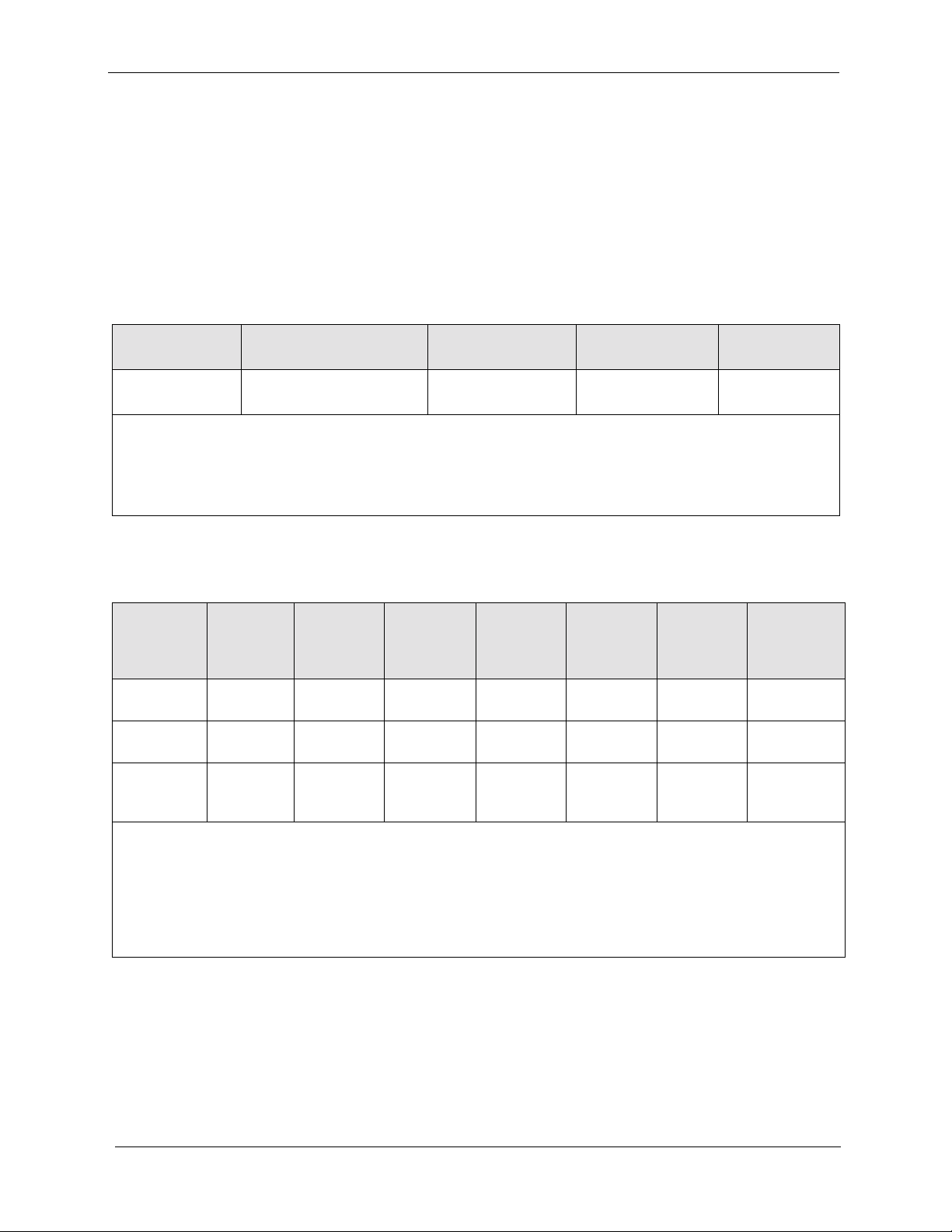
What You Must Purchase
The following items must be purchased to install ISDN.
DBS Equipment
If you are installing the ISDN in a single-cabinet system, order the equipment
included in Table 1-1. For two-cabinet systems, see Table 1-2.
Table 1-1. ISDN Hardware requirements for single-cabinet systems
CPC-EX
(VB-43415)
1 1
SCC-B
(VB-43421)
(See Note 1.)
ISDN Trunk Card
(VB-43571)
1
(See Note 3.)
MDF Card
(VB-43562)
11
Sync Unit
(VB-43563)
Notes:
1. SCC-B with ROM 1.3 or later is required if the central office does not provide ISDN dial tone.
2. Fractional (per port) Assignments requires the VB-43511A version of the loop start trunk card.
3. COP 1.07 or later is required with ISDN PRI Trunk Card VB-43571 for CPC-EX 2.2.
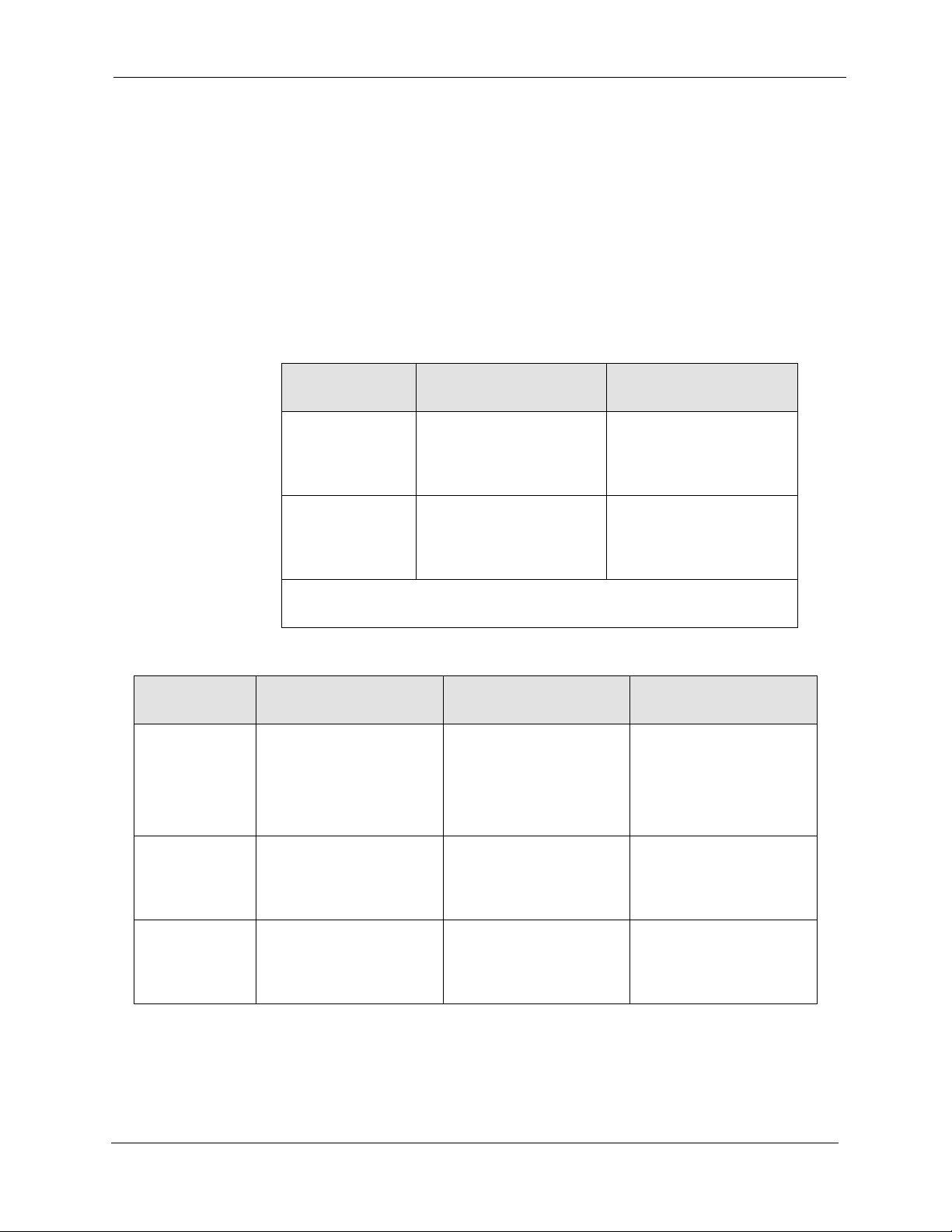
Table 1-2. ISDN Hardware requirements for double-cabinet systems
ISDN
Location
ISDN in the
Master
ISDN in the
Slave
ISDN in both
Master and
Slave
Notes:
CPC-EX
(VB-43415)
11 1110 1
111111 1
112211 1
SCC-B
(VB-43421)
(See Note 1)
ISDN Trunk
Card
(VB-43571)
(See Note 3.)
MDF
Card
(VB-43562)
Sync
Unit
(VB-43563)
ISDN Cable
(VB-43564)
Cable Kit
(VB-43110)
(See Note 2.)
1. SCC-B with ROM 1.3 or later is required if the central office does not provide ISDN dial tone.
2. Version 1.2 of the Cable Kit is required for ISDN.
3. Fractional (per port) Assignments requires the VB-43511A version of the loop start trunk card.
4. COP 1.07 or later is required with ISDN PRI Trunk Card VB-43571 for CPC-EX 2.2.
1-8 DBS-EX23-530 April 2000

Introduction to the ISDN Interface Pre-Installation Requirements
CSU Equipment
The installer must provide a Channel Service Unit (CSU) plus CSU cabling.
The CSU equipment must meet the specifications contained in T able 1-3. See
page 2-12 for instructions on installing the CSU.
Table 1-3. CSU equipment required for ISDN
Item Specifications Vendors
CSU
CSU
Cabling
The Channel Service Unit (CSU) must
comply with FCC Part 15 and Part 68. The
CSU is installed between the DBS and the
public network. The CSU provides alarm,
diagnostic, and monitoring functions, as
well as network protection.
Each CSU requires a network cable and an equipment cable. The network cable connects from the
CSU to the network interface. The equipment cable
connects from the CSU to the DBS ISDN MDF
card.
For Kentrox CSUs
The network cable requires a female DB-15 connector and an RJ48C connector. The equipment
cable requires a male DB-15 connector and an
RJ48C connector.
To simplify installation, you can order the prefabricated cables shown in the “Vendors” column.
If you fabricate your own ISDN cables, you should
use 24 AWG stranded cable that includes shielding
for each pair. For best results, use the cable listed
under “Vendors.”
For Premier CSUs
You must fabricate your own cables for the Premier
CSU. The network cable requires two RJ48C connectors. The equipment cable connects to an RJ48C
connector on the ISDN MDF card and to four
screw-down terminals on the CSU.
For both cables, use 24 AWG stranded cable that
includes shielding for each pair. For best results,
use the cable listed under “Vendors.”
The following CSUs have been used successfully with the DBS ISDN.
Kentrox
Kentrox T-SERV II
or
Kentrox T-SMART
(Kentrox can be contacted at 1-800-733-
5511.)
For Kentrox CSUs
Kentrox offers prefabricated cables f or their CSUs.
For the network cable, order part number 01-
93010151. For the equipment cable, order part
number 01-93010121.
If you fabricate your own cables, use 24 AWG
stranded cable that includes shielding for each pair.
Belden (Richmond, IN) offers stranded cable that
complies with these specifications. Order part
number 8723.
Revised April 2000 DBS-EX23-530 1-9

Pre-Installation Requirements
Introduction to the ISDN Interface
1-10 DBS-EX23-530 April 2000

Chapter 2. Installation
This section describes guidelines and procedures for installing the ISDN
Interface. Once the ISDN Interface is installed, refer to Chapter 3 - “Quick
Start Programming” or Chapter 4 - “Programming Reference” for
programming instructions.
This chapter covers the following topics.
Guidelines 2-3
Hardware Requirements 2-3
Maximums 2-3
Trunk Assignments for Single-Cabinet Systems 2-5
Trunk Assignments for Double-Cabinet Systems 2-6
Installation Procedures 2-12
Installing the CSU 2-12
Topic Page
Installing an ISDN in a Single Cabinet 2-14
Installing ISDN in a Double Cabinet with ISDNs in the
Master and Slave
2-23
Revised April 2000 DBS-EX23-530 2-1

2-2 DBS-EX22-530 Revised April 2000

Installation Guidelines
Guidelines
Read the following guidelines before beginning ISDN installation.
Installation instructions begin on page 2-14.
Hardware Requirements
• The system configuration determines what cards and cables must be
purchased for ISDN. See “DBS Equipment” on page 1-8 for more
information.
• The installer must provide a Channel Service Unit (CSU) that complies
with FCC Part 15 and Part 68. The CSU is installed between the DBS and
the public network. The CSU provides alarm, diagnostic, and monitoring
functions, as well as network protection.
See “CSU Equipment” on page 1-9 for details on purchasing CSUs.
Maximums
• One ISDN card can be installed per cabinet; the ISDN card must be
installed in the “EC/TRK” slot.
• The number of ISDN cards that can be installed in two-cabinet systems
depends on the sizes of the connected systems. Table 2-1 shows ISDN
maximums for two-cabinet systems.
Note: The DBS 72 + DBS 40 combination does not support ISDN.
Table 2-1. EC/TRK slot usage for ISDN
System Size EC/TRK Slot
Usage for ISDN
Master Slave
DBS 40 + DBS 40 No Yes
DBS 72 + DBS 40 No No
DBS 72 + DBS 72 No Yes
DBS 96 + DBS 40 Yes Yes
DBS 96 + DBS 72 Yes Yes
DBS 96 + DBS 96 Yes Yes
Revised April 2000 DBS-EX23-530 2-3

Guidelines
Installation
• Fractional ISDN can be used when fewer than 23 ISDN trunks are needed.
Fractional ISDN allows you to use only a portion of the 23 channels
provided on the ISDN card.
• Fractional ISDN per port assignments require the VB-43511A version of
the loop start trunk card. The older VB-43511 version may be used with
fractional ISDN but requires that the trunks be assigned in blocks of 8.
• Though each ISDN Interface provides 23 trunk channels, ISDN trunks do
not increase the overall trunk capacity of the DBS. Each ISDN channel
subtracts from the total number of analog trunks that can be installed. The
number of analog trunks that can be used are decremented in quantities of
1 for each ISDN channel user.
Tables 2-2 through 2-4 show the possible combinations of analog and
digital trunks assignments based on system size.
The trunk numbering shown in these tables is determined by backplane
trunk port assignments. Therefore, the numbering cannot be changed.
Note: Analog trunks are numbered beginning with “1.” ISDN trunk
channels are numbered beginning with the highest trunk channel used.
2-4 DBS-EX23-530 Revised April 2000
Installation Guidelines
Trunk Assignments for Single-Cabinet Systems
• Programming is not required to associate trunk ports with slot locations.
However, you must use programming to specify that a combination of
ISDN and analog trunks is installed, and you must also specify how many
ISDN channels are used.
• Fractional ISDN per port assignments require the VB-43511A version of
the loop start trunk card. The older VB-43511 version may be used with
fractional ISDN but requires that the trunks be assigned in blocks of 8.
Table 2-2. ISDN and analog trunk assignments, DBS 40
Trunk
Number
1 ISDN channel 16 Analog trunk 1
↓↓ ↓
8 ISDN channel 9 Analog trunk 8
9 ISDN channel 8 ISDN channel 8
↓↓ ↓
16 ISDN channel 1 ISDN channel 1
Note: Since the DBS 40 supports a maximum of 16 trunks, all 23
channels of the ISDN cannot be used.
Table 2-3. ISDN and analog trunk assignments, DBS 72
Trunk
Number
1 Analog trunk 1 Analog trunk 1 Analog trunk 1
2 ISDN channel 23 Analog trunk 2 Analog trunk 2
↓↓ ↓ ↓
8 ISDN channel 17 Analog trunk 8 Analog trunk 8
23-Channel ISDN Fractional ISDN
Fractional ISDN
using 16 Channels
using 16 Channels
Fractional ISDN
using 8 Channels
Fractional ISDN
using 8 Channels
9 ISDN channel 16 ISDN channel 16 Analog trunk 9
↓↓ ↓ ↓
16 ISDN channel 9 ISDN channel 9 Analog trunk 16
17 ISDN channel 8 ISDN channel 8 ISDN channel 8
↓↓ ↓ ↓
24 ISDN channel 1 ISDN channel 1 ISDN channel 1
Revised April 2000 DBS-EX23-530 2-5

Guidelines
Table 2-4. ISDN and analog trunk assignments, DBS 96
Installation
Trunk
Number
1 Analog trunk 1 Analog trunk 1 Analog trunk 1
↓↓↓↓
8 Analog trunk 8 Analog trunk 8 Analog trunk 8
9 Analog trunk 9 Analog trunk 9 Analog trunk 9
10 ISDN channel 23
↓↓↓↓
16 ISDN channel 17 Analog trunk 16 Analog trunk 16
17 ISDN channel 16 ISDN channel 16 Analog trunk 17
↓↓↓↓
24 ISDN channel 9 ISDN channel 9 Analog trunk 24
25 ISDN channel 8 ISDN channel 8 ISDN channel 8
↓↓↓↓
32 ISDN channel 1 ISDN channel 1 ISDN channel 1
23-Channel ISDN Fractional ISDN
using 16 Channels
Fractional ISDN
using 8 Channels
Trun k Ass ign men ts for Double-Cabinet Systems
• When ISDN is used in a two-cabinet system, the number of ISDN channels
that can be assigned in each cabinet depends on the master/slave
designation.
• Fractional ISDN per port assignments require the VB-43511A version of
the loop start trunk card. The older VB-43511 version may be used with
fractional ISDN but requires that the trunks be assigned in blocks of 8.
The following table shows the maximum number of ISDN channels that
can be assigned in two-cabinet systems.
2-6 DBS-EX23-530 Revised April 2000

Installation Guidelines
Table 2-5. Maximum ISDN assignments for two-cabinet systems
System Size Master Slave
DBS 40 + DBS 40 8 analog trunks 16 ISDN trunks
DBS 72 + DBS 72 16 analog trunks 23 ISDN trunks
1 analog trunk
DBS 96 + DBS 40 23 ISDN trunks
16 ISDN trunks
9 analog trunks
DBS 96 + DBS 72 23 ISDN trunks
9 analog trunks
DBS 96 + DBS 96 23 ISDN trunks
9 analog trunks
23 ISDN trunks
1 analog trunk
23 ISDN trunks
9 analog trunks
• Two-cabinet systems use the same trunk numbering scheme as singlecabinet systems: analog trunks are numbered from “1” upward; ISDN
trunk channels are numbered downward from the highest channel used.
Tables 2-6 through 2-10 show trunk numbering for two-cabinet systems
using the maximum number of ISDN channels.
Table 2-6. ISDN and analog trunk assignments, DBS 40 + 40 (16-channel fractional ISDN in the
slave)
Trunk
Master Cabinet Slave Cabinet
Number
1 Analog trunk 1
↓↓ Ν/Α
8 Analog trunk 8
9 ISDN channel 16
↓ N/A ↓
16 ISDN channel 9
17 ISDN channel 8
↓Ν/Α ↓
24 ISDN channel 1
Revised April 2000 DBS-EX23-530 2-7

Guidelines
Table 2-7. ISDN and analog trunk assignments, DBS 72 + DBS 72 (23-channel ISDN in the slave)
Installation
Trunk
Number
Master Cabinet Slave Cabinet
1 Analog trunk 1
↓↓ Ν/Α
8 Analog trunk 8
9 Analog trunk 9
↓↓ N/A
16 Analog trunk 16
17 Analog trunk 1
18 ISDN channel 23
↓Ν/Α ↓
24 ISDN channel 17
33 ISDN channel 16
↓Ν/Α ↓
40 ISDN channel 9
41 ISDN channel 8
↓Ν/Α ↓
48 ISDN channel 1
2-8 DBS-EX23-530 Revised April 2000

Installation Guidelines
Table 2-8. ISDN and analog trunk assignments, DBS 96 + DBS 40 (23-channel ISDN in the master;
16-channel ISDN in the sla ve)
Trunk
Number
Master Cabinet Slave Cabinet
1 Analog trunk 1
↓↓ Ν/Α
8 Analog trunk 8
9 Analog trunk 9
10 ISDN channel 23
↓↓ N/A
16 ISDN channel 17
17 ISDN channel 16
↓↓ Ν/Α
24 ISDN channel 9
25 ISDN channel 8
↓↓ Ν/Α
32 ISDN channel 1
33 ISDN channel 16
↓Ν/Α ↓
40 ISDN channel 9
41 ISDN channel 8
↓Ν/Α ↓
48 ISDN channel 1
Revised April 2000 DBS-EX23-530 2-9

Guidelines
Table 2-9. ISDN and analog trunk assignments, DBS 96 + DBS 72 (23-channel ISDN in the master;
23-channel ISDN in the sla ve)
Installation
Trunk
Number
Master Cabinet Slave Cabinet
1 Analog trunk 1
↓↓ Ν/Α
8 Analog trunk 8
9 Analog trunk 9
10 ISDN channel 23
↓↓ N/A
16 ISDN channel 17
17 ISDN channel 16
↓↓ Ν/Α
24 ISDN channel 9
25 ISDN channel 8
↓↓ Ν/Α
32 ISDN channel 1
33 Analog trunk 1
34 ISDN channel 23
↓Ν/Α ↓
40 ISDN channel 17
41 ISDN channel 16
↓Ν/Α ↓
48 ISDN channel 9
49 ISDN channel 8
↓Ν/Α ↓
56 ISDN channel 1
2-10 DBS-EX23-530 Revised April 2000

Installation Guidelines
Table 2-10. ISDN and analog trunk assignments, DBS 96 + DBS 96 (23-channel ISDN in the master;
23-channel ISDN in the sla ve)
Trunk
Number
Master Cabinet Slave Cabinet
1 Analog trunk 1
↓↓ Ν/Α
8 Analog trunk 8
9 Analog trunk 9
10 ISDN channel 23
↓↓ N/A
16 ISDN channel 17
17 ISDN channel 16
↓↓ Ν/Α
24 ISDN channel 9
25 ISDN channel 8
↓↓ Ν/Α
32 ISDN channel 1
33 Analog trunk 1
↓Ν/Α ↓
40 Analog trunk 8
41 Analog trunk 9
42 ISDN channel 23
↓Ν/Α ↓
48 ISDN channel 17
49 ISDN channel 16
↓Ν/Α ↓
56 ISDN channel 9
57 ISDN channel 8
↓Ν/Α ↓
64 ISDN channel 1
Revised April 2000 DBS-EX23-530 2-11
Installation Procedures
Installation
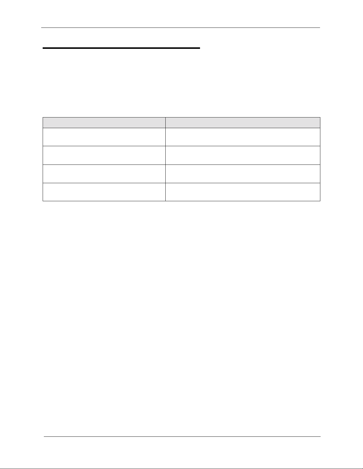
Installation Procedures
The following procedures provide step-by-step instructions for installing the
CSU and the ISDN Interface. The ISDN procedure that you should use
depends on the type of system you have and the number of ISDNs you are
installing.
If you’re installing ... Use this procedure...
A ISDN in a single cabinet “Installing an ISDN in a Single Cabinet” (page 2-
14)
One ISDN in a double cabinet, with the
ISDN located in the master
One ISDN in a double cabinets, with the
ISDN located in the slave
ISDNs in both the master and slave “Installing an ISDN in a Double Cabinet with
“Installing an ISDN in a Single Cabinet” (page 2-
14)
“Installing an ISDN in a Double Cabinet with the
ISDN in the Slave” (page 2-21)
ISDNs in the Master and Slave” (page 2-23)
Installing the CSU
The following instructions explain how to install the CSU. See “CSU
Equipment” on page 1-9 for specifications on CSUs and CSU cabling.
Note: The CSU can be powered locally or through the CO line. Also, a
locally powered CSU should be connected to an Uninterruptible Power
Supply (UPS) to provide battery backup in case of AC power failures.
1. Connect the equipment cable from the DBS MDF card to the equipment
side of the CSU, as shown in Figure 2-1.
2-12 DBS-EX23-530 Revised April 2000
 Loading...