

100 Craftway Dr.
Littlestown, Pennsylvania 17340-0128
Phone: 717-359-7131
INSTALLATION INSTRUCTIONS:
DB5000 - LARGE INGROUND UPLIGHT
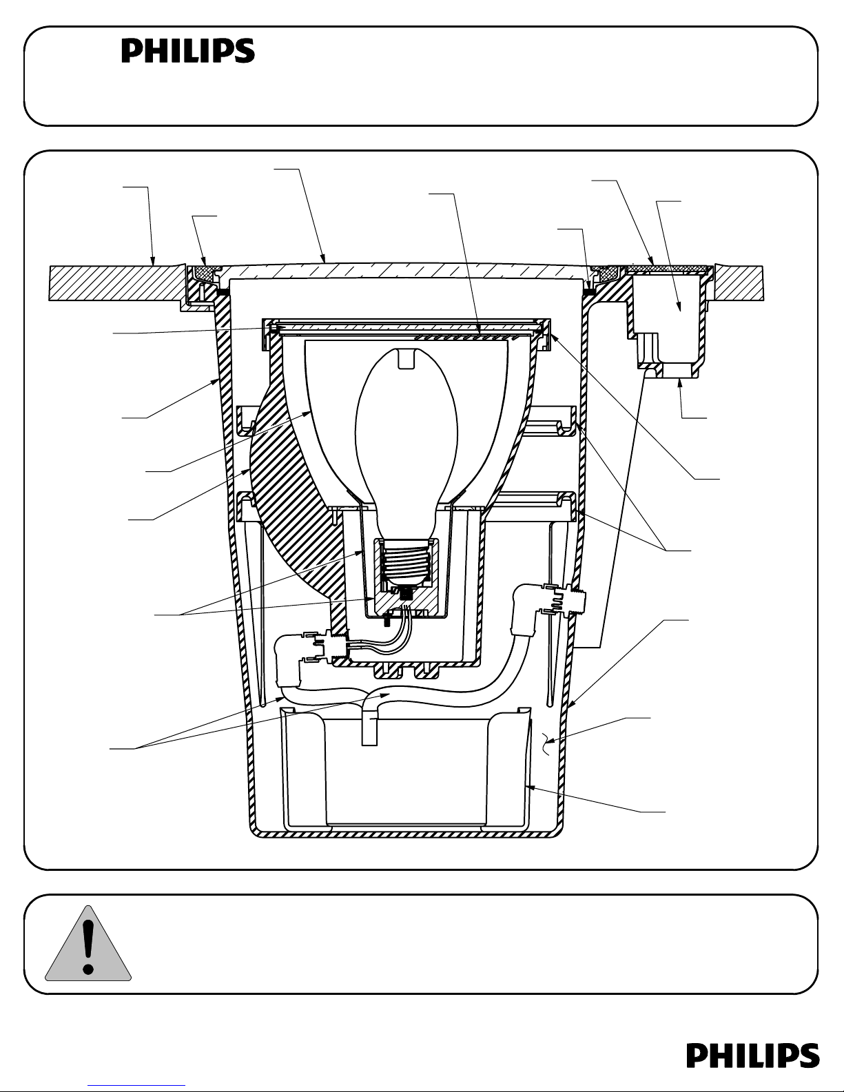
PAVER
ADAPTER
(OPTIONAL)
LAMPING
MODULE
LENS
HOUSING
RIBS
REFLECTOR
LAMPING
MODULE
MAIN
LENS
LENS
FRAME
INTERNAL
ACCESSORY
(OPTIONAL)
WIRING
COMPARTMENT
COVER
LENS
GASKET
WIRING
COMPARTMENT
(MUST BE SEALED
WITH SUPPLIED
RE-ENTERABLE
ENCAPSULANT)
3/4" CONDUIT
ENTRY (3X)
TWIST-LOCK
LENS FRAME
LAMPING
MODULE
GIMBAL
SOCKET &
BRACKET
LIQUIDTIGHT
CABLES
NOTE : FIXTURE STYLE, ACCESSORIES, OPTICS AND BALLAST TYPE WILL VARY WITH FIXTURE OPTIONS.
This fixture is intended for installation in accordance with the National Electrical Code and local code
specifications. Failure to adhere to these codes and instructions may result in serious injury and/or damage
to the ballast and void the warranty. These instructions do not purport to cover all details or variations in
equipment, nor to provide for every possible contingency related to installation, operation, maintenance,
or mounting situation. Should specific problems occur that are not addressed by these instructions, contact
your Sales Representative or distributor for assistance. Retain these instructions for future reference.
MAIN
HOUSING
BALLAST
COMPARTMENT
BALLAST MODULE
(HID ONLY)
32001316, revision J
page 1 of 4

SAFETY WARNING:
ALWAYS TURN FIXTURE OFF/DISCONNECT POWER AND ALLOW TO COOL BEFORE
PERFORMING ANY MAINTENANCE, INCLUDING RELAMPING AND CLEANING!
This fixture can become very HOT! The fixture housing and lens, especially if it is glass, can become hot enough
to blister hands. Attention should be paid to where the fixture is mounted, particularly if it can be touched by
children or pets. To help prevent premature failure, decreased performance, overheating and risk of fire, keep
fixture and lens clean and free of leaves, mulch, debris and mineral deposits from water. The fixture and lens
can be cleaned using a soft cloth and a solution of mild liquid soap and warm water. Wipe clean and dry with a
soft, lint-free dry cloth. Avoid polishing fixture or lens.
INSTRUCTIONS PERTAINING TO A RISK OF FIRE OR INJURY TO PERSONS
IMPORTANT SAFETY INSTRUCTIONS - SAVE THESE INSTRUCTIONS!
WARNING - Lamp gets HOT quickly! To reduce the risk of FIRE OR INJURY TO PERSONS:
Do not operate fixture with a missing or damaged lens/lens assembly.
Contact only switch or plug when turning fixture on or off. Do NOT touch hot lens or housing.
Turn off or unplug fixture and allow to cool before relamping. Keep lamp away from combustibles.
Do NOT touch lamp with bare hands at any time, use a soft cloth as oil from skin may damage lamp.
CAUTION:
WARNING: TURN POWER OFF BEFORE INSTALLING OR PERFORMING ANY MAINTENANCE ON THIS FIXTURE.
1.
Failure to do so may result in severe injury or death.
The housing should not be installed in insulating materials such as bark, vermiculite, etc. for the full depth
2.
of the housing. Surface use of these materials around BUT NOT ON TOP of the fixture is acceptable.
IMPORTANT: To prevent overheating, regularly check lens and keep it clean and free of debris such as
3.
dirt, sand, leaves, mulch, etc.
Conduit entry ways should be properly sealed around threads and duct seal should be used in the
4.
conduit around the wires to prevent water entry through the conduit. Unused conduit entry ways
should be properly plugged and sealed.
The fixture should not be installed in low lying areas or where water may accumulate and stand for long
5.
periods of time.
Soil should be mounded up around the fixture to promote drainage.
6.
Do not install fixture within 10 feet (3 meters) of a pool, spa or fountain
7.
Failure to do so will void warranty and could cause a fire.
Failure to do so will void warranty.
.
INSTALLATION
IF A MOUNTING ACCESSORY IS USED, IT MUST BE ATTACHED TO THE HOUSING BEFORE
CONTINUING! KEEP DIRT COVERS IN PLACE ACCORDING TO DIRECTIONS.
Step 1:
Excavate soil for fixture, or fixture with mounting accessory, as well as conduits.
NO ACCESSORY
Dirt Covers
DB5CMF
Dirt Covers
Mounting
Screws
DB5PA
Dirt Covers
Paver
Adapter
(DB5PA)
Soil
or cement
removed for fixture
and conduits
32001316, revision J
Concrete
mounting
frame
(DB5CMF)
Back fill
between
housing &
DB5CMF.
Mounting
Screws
page 2 of 4

Step 2:
Connect conduit using
thread sealant.
Unused conduit entry
ways should be properly
plugged and sealed.
Supply wires
pulled through
conduit
Junction Box
Step 3:
Set aside junction box dirt
cover (retain for future use). Pull
wires through conduit into junction
box. The contractor must pull a
ground wire or make a ground
connection to a metal conduit
system. Place duct seal in the
conduits around the wires.
Step 4:
Duct
Seal
Conduit
(By others)
Backfill around housing and mounting accessory (if used) with dirt, cement or decorative stone as
Failure to properly seal
conduit may allow water
into junction box and
will void the warranty.
required for finishing the particular installation. DO NOT back fill with bark or vermiculite.
Step 5:
Connect supply leads to the fixture wiring (see below) using the supplied liquid tight wire nuts. Be sure
colored fixture supply wire, per table below, matches supply voltage. Replace junction box dirt cover.
WARNING: 3 UNUSED VOLTAGE WIRES MUST BE INDIVIDUALLY CAPPED OFF USING LIQUID TIGHT
WIRE NUTS (BY OTHERS). FAILURE TO DO SO WILL VOID WARRANTY, DAMAGE FIXTURE, AND
COULD RESULT IN INJURY.
3 Liquid Tight Wire Nuts
(Supplied)
voltage taps -
COLOR
WHITE
BLACK
ORANGE
RED
BLUE
GREEN
VOLTAGE
Quad-tap
Tri-tap
50Hz
120/277V
127/220V
NEUTRAL NEUTRAL NEUTRAL NEUTRAL NEUTRAL
120V 120V 120V 120V 127V
208V 220V 220V
240V 240V
277V 277V 277V
GROUND GROUND GROUND GROUND
None
347V
None
None
None None
None
GROUND
WHITE
to supply
neutral
GREEN
to supply
ground
Supply hot
Unused
individually
capped
(3 places)
ENSURE GASKET SEATING
SURFACES ARE CLEAN AND
FREE OF DEBRIS BEFORE SEALING.
Wiring Compartment Cover
(Stainless steel or brass)
HID Lamping Module
Ensure ballast
wattage matches
lamp module
Ballast Module
(Core & Coil
HID Only)
Step 7:
Remove round dirt cover. Attach ballast
module (HID only) and lamping module using
the cordsets. Aim lamping module in direction
desired.
Take care not to
pinch any wires.
3
2
If debris in screw holes prevents proper
gasket seating, holes must be blown
clear or cleared with a 1/4-20 tap.
Step 6:
Remove junction box dirt cover.
Screw the wiring compartment cover
to housing with 70 in-lb of torque in an
1
alternating pattern as shown below.
4
Incandescent,
Fluorescent &
Electronic HID
Lamping Module
(INC/FL/eHID only)
32001316, revision J
page 3 of 4

Step 8: NOTE: To help decrease moisture
, energize fixture for 20
minutes prior to attaching main lens. Place main lens assembly
on the housing. (Do not remove protective tape on edge of
lens). Screw lens frame to housing with 70 in-lb of torque in an
alternating star pattern as shown.
DO NOT
torque in a radial
pattern (1 to 3 to 5 etc).
1
Torque sequence
6
3
4
5
2
Main Lens Assembly
(Main Lens, Lens Gasket & Lens Frame)
RELAMPING
All fixtures ship pre-lamped unless otherwise specified. Fixtures may be relamped in the field or in a
controlled indoor environment. It may be desirable to keep spare lamping modules to field swap. MAKE SURE
POWER IS OFF BEFORE RELAMPING. Remove lens frame, main lens and lens gasket. Inspect gasket for damage
and replace, if necessary.
Relamping indoors: Remove lamping module from main housing and disconnect cordset. Replace lamping
module with a pre-lamped one. Re-seal fixture per Step 8 above - ensure gasket seating surfaces are clean and
free of debris. Take lamping module to work area and relamp per below. Keep this pre-lamped module for
future use.
Relamping in the field: Twist the lens frame on the lamping module and lift up to remove. Remove lamp module
lens and any internal accessory. Replace lamp with a new one of identical electrical characteristics. [NOTE: For
metal halide T6 (G12 base) lamps, Bronzelite recommends using only Philips MasterColor™ lamps or
GE ConstantColor CMH™ lamps. If using a lamp from another manufacturer, ensure it is electrically compatible
with supplied ballast.] For T6 optics, if it is necessary to remove the optics assembly, position the bottom band of
the optics assembly around the four pins indicated in the "T6 Optics - Seating Illustration" below and simply
press-fit into place.
Pins
Bottom
Band
T6 Optics - Seating Illustration
Replace internal accessory (if applicable) and lamp module lens, re-seat lamp module lens
frame and twist to secure. Re-seal the fixture per Step 8 above - ensure gasket seating surfaces are clean and
free of debris.
32001316, revision J
page 4 of 4
 Loading...