

Page 1
PHILIPS
CONSUMER ELECTRONICS
PHILIPS
OuOOOOQ *0 02959
îC'.v«'> fv Л CA»rt-5
ОДТ
ЗЕВЕ
DAT850
/ /
///
Digital audio tape deck
Platine à cassette audio numérique
DAT-Deck
DAT-deck
Registratore DAT
Page 2

English
pages
Français
Deutsch
Nederlande
Italiano
page26
seite49
pagina72
pagina95
Page 3

English
FEATURES
1. Five 2-channeI modes
• 48 kHz mode: Sampling frequency of 48 kHz, 16-bit linear
quantization
• 44 kHz mode: Sampling frequency of 44.1 kHz, 16-bit
linear quantization
• 32 kHz mode: Sampling frequency of 32 kHz, 16-bit linear
quantization
• 32 kHz LP (Long Play) mode: Sampling frequency of
32 kHz, 12-bit non-linear quantization
• 44 kHz WT (Wide Track, playback only) mode: Sampling
frequency of 44.1 kHz, 16-bit linear quantization
2. SCMS (Serial Copy Management System)
• Only one digital recording can be made of CD software
3. High-precision fine-tracking digital servo mechanism
• Philips's high-precision mechanism makes possible the
LP (Long Play) mode
4. Fourth-order delta sigma type 1-bit ADC (Analog to
Digital Converter)
5. 1-bit DAC (PEM DD converter)
6. AUTO ID EDIT function
• The optimum START ID position is automatically shown
in the display
7. Sampling monitor facility
8. 20-dot digital meter (with peak hold function)
• The digital peak display shows the margin
9. Tray type cassette loading
10. Direct access playback with 10-key remote control
11. Separate sub code keys
(with Renumber function)
12.10-key wireless remote control
13. Digital input/output terminals (Coaxial/Optical)
• Meeting digital audio interface standards
14. SOURCE selector (Digital/Analog)
REMOTE CONTROL SYSTEM
This is a convenient system which has been originated and
developed by Philips. Before starting operation, connect the
remote cable as shown on page 7. The followings are the
brief explanation of its major performances:
Synchronized Recording
Synchronized recording refers to the process in which the
DAT deck starts recording in synchronism with the CD player.
Please study these instructions carefully before starting to
operate the unit, to use the unit correctly. We take no responsibility
for any problems resulting from misuse of this unit if it is operated,
by methods other than those given in this manual.
On operating this unit:
Since this unit incorporates a microprocessor which controls
various functions, please read the description and cautions
(notes) for each item carefully before use.
If operated incorrectly, the required functions may not be per
formed. In this case, turn the power OFF then turn it ON again
and see if correct operation has become possible.
• Types of DAT cassettes
Mode Maximum recording time
Cassette
R-120
R-90 1 h.30 min.
R-60
R-46
Notes:
1. Cassettes recorded in the 32k-LP mode by this unit cannot
be played back using DAT decks exclusively for the 48k or
32k mode.
The 44k-WT mode is used only when DAT prerecorded tapes
made from master tapes by the contact printing process are
played.
2. DAT: abbreviation of Digital Audio Tape
LP: abbreviation of Long play
WT: abbreviation of Wide track
48k/44k/32k mode 32k-LP mode
2 hours
1 hour
46 minutes 1 h.32 min.
4 hours
3 hours
2 hours
Important note for users in U.K.:
The U.K. version is not fitted with a mains plug.
When fitting a mains plug to the mains lead note that the
wires in the mains lead are coloured with the following code:
Blue = Neutral, Brown = Live.
As these colours may not correspond with the colour mark
ings identifying theterminals in your plug proceed as follows:
the Brown wire must be connected to the terminal which is
marked with the letter L or coloured Red.
The Blue wire must be connected to the terminal which is
marked with the letter N or coloured Black.
Note: This apparatus must be protected by a 3 Amp Fuse if a
13 Amp plug is used or, if any other type of plug is used, by
a 5 Amp Fuse either in the plug or adapter or atthe distribution
board. If in doubt consult a qualified electrician.
DO NOT CONNECT EITHER WIRE TO THE EARTH TERMINAL
IN THE PLUG WHICH IS MARKED BY THE LETTER E OR BY
THE SAFETY EARTH SYMBOL OR COLOURED GREEN OR
GREEN-AND-YELLOW
Page 4
CAUTIONS
1. Safety hints
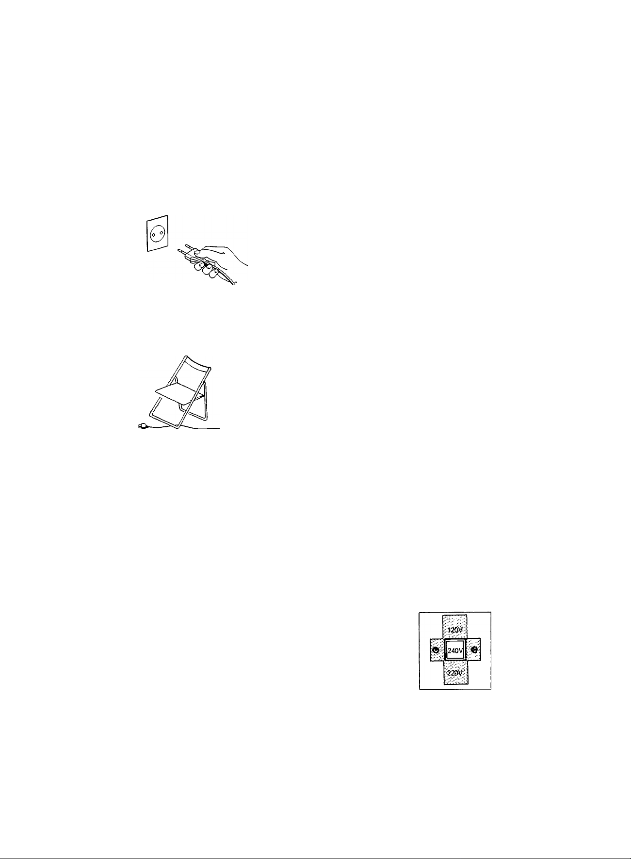
1. Be sure to pull the plug, not the cord. (Fig. 1)
2. Do not handle the power cord with wet hands.
3. Do not damage the power cord. (Fig. 2)
4. if the deck is not to be used for an extended period, unplug
the power cord.
5. Do not remove the cabinet. To avoid electric shocks, do not
touch parts inside the deck. Consult a dealer for repairs.
6. Do not permit any liquids or objects to get inside the deck.
The deck could be damaged if water or flammable or metallic
objects get inside.
Pull the plug when disconnecting the cord.
Note:
This diagram does not represent a U.K. mains plug.
Fig.1
5. Condensation
1. if condensation forms on the head drum, the heart of a DAT
unit, the tape may stick to the head drum and may be damaged.
2. Condensation may occur in the following cases:
• When the unit is moved from a cold place to a warm place,
• In a room immediately after its heating has been switched
ON, or in a place where the deck is exposed to cold air
from a cooler.
• In a place which is excessively humid.
3. When condensation could have occurred in the DAT deck
such as when it is moved from a cold place to a warm place,
turn the POWER switch ON and leave it for about one hour
before using it.
When condensation is likely to occur, do not leave a cassette
in the deck. It is recommended that you always remove
cassette tapes from the deck when it is not in use.
• Use the deck where the ambient temperature is from
5°C(41°F)to35°C(95°F).
When the deck is used in a cold place, condensation may
occur more frequently.
6. Timer switch setting
Set the TIMER switch to “REG” or "PLAY" v;hen performing
timer recording or playback. At other times, be sure to set the
TIMER switch to OFF.
Take care not to damage the power cord.
Fig. 2
2. Installation
1. Avoid placing the unit on or adjacent to an amplifier, to prevent
hum which is produced by some types of amplifiers. Move
the unit to a place where it will not be affected by the amplifier.
Keep the unit as far as possible from a TV set.
2. Avoid installing the unit in a location subject to excessively
high temperatures (e.g. direct sunlight, near a heater, etc.),
excessive humidity, dust, vibrations or magnetic fields.
3. Cleaning the heads
If this unit is used for a long period of time, its heads will become
dirty. When they become excessively dirty, recording and
playback will not be satisfactory. Because of this, clean the heads
every 30 hours of playing time with a cleaning cassette available
from your audio store.
Press the e/o REC and ► PLAY buttons then, after another 10
seconds, press the ■ STOP button.
REC OFF PLAY
TIMER
7. Heat radiation
Be careful not to block the ventilation holes so that the tem
perature inside the deck does not rise excessively. Do not install
the unit in a badly ventilated place.
SELECTING THE AC SUPPLY VOLTAGE
When this deck is used in an area where the supply voltage
is different from the preset voltage, reset the voltage selector
to the correct position.
Slide the voltage selector with a screwdriver so that the desired
voltage marking is in the window.
4. Volume setting
In DAT, digital signals are recorded and played back; because
of this, it is difficult to set the appropriate volume using the level
of noise as a reference. Do not raise the volume excessively
even if the beginning of a tune seems quiet. Otherwise, when
the level of the sound rises, it could damage the speakers or
other equipment.
Caution:
Disconnect supply cord before changing the voltage.
Page 5

NAMES OF PARTS AND THEIR FUNCTIONS (Refer to page 118.)
• Front panel
© ON/OFF switch
® Cassette tray
©REMOTE SENSOR
Receives infrared signais transmitted from the remote control
unit.
©Sub code buttons
• Start iD erase (ERASE)
• START ID
• END/RENUMBER
Press during recording to record the End code.
If pressed in the stop mode, it is possible to set new program
numbers.
• AUTO ID EDIT
©Display window
© Start ID detect/memory/erase indicator
® RENUMBER indicator
© Program number indicator (PRGM NO)
® Absolute time indicator (A TIME)
© Mode indicator
® Sampling frequency indicator
® Digital input indicator (DIGITAL INPUT)
® Tape/sampling monitor indicator
(TAPE SAMPLING MONITOR)
© REPEAT indicator
® 32k-LP mode indicator
® Next number indicator (NEXT NO)
© Level meter indicators
® Digital counter
© Copy prohibit indicator (COPY PHBT)
© Emphasis indicator (EMPHASIS)
© Digital peak display
• When the following operations are performed, these indications
are displayed.
®REC TIME switch
Select the recording time in different recording modes.
^^^ecording
^\tTiode
Switch positif
Standard (STD)
LONG
• The REC TIME switch is not used when recording a digital
signal in the 48k and 44k modes. The source signal is
recorded as it is.
©Tape operations buttons
■ STOP/OPEN-CLOSE;
Press to stop the tape.
Press to open and close the cassette tray.
PREVIOUS/AUTO SEARCH:
NEXT ugg^ designate the number of tunes.
REWIND/SEARCH:
WIND When pressed in the stop mode, the fast-forward
or rewind operation starts, and speeded-up sound
can be heard at a lower level (cue, review function).
► PLAY:
Press to start recording and playback.
Analog
recording
48k mode 32k mode
32k-LP mode
Digital recording
32k-LP mode
48k/44k mode
II PAUSE:
Press to stop the tape temporarily.
To release this mode, press the ► PLAY button.
•¡0 REC/REC MUTE:
When recording, press the ► PLAY button while
pressing this button. To enter the “rec-pause” mode,
press together with the ll PAUSE button. When this
is pressed during recording, the rec mute operation
is engaged.
® PHONES jack and PHONES LEVEL control
TOP: When the deck is set to the rec-pause mode or rec mode
at the beginning of tape.
-00:01: After TOP has been displayed and a tape is recorded
and then rewound, this is displayed.
EE: When an End code is detected or recorded, the deck stops
automatically and this is displayed,
no TAPE: When the cassette tray is closed without a cassette
tape loaded.
©REPEAT button
Used to repeat all the tunes on the tape.
©DISPLAY button
Used to select the mode of the display.
When the power is first switched on, “A TIME” (absolute time)
is displayed. Every time this button is pressed, the display
alternates between the counter mode and “A TIME”.
©Tape counter reset button (RESET)
© REC LEVEL control (Analog)
Adjust the recording level with this control.
The inner knob is for the left channel and the outer knob,
the right channel.
©TIMER switch
Used when timer recording or playback is to be performed
using an audio timer. Normally set to the OFF position.
©SOURCE switch
Set to according to the type of input signal. (Analog/optical/
coaxial).
• Rear panel
©ANALOG (LINE) IN/OUT terminals
(Refer to page 7.)
® REMOTE INTERNAL/EXTERNAL switch
Set this switch to INTERNAL when using this unit alone, and
set to EXTERNAL when using this unit together with other
component, which bears “RC-5" logo and is equipped with a
remote sensor, such as the Philips amplifier.
©REMOTE CONT. terminals
When connected to a CD player, cassette deck or amplifier with
REMOTE CONT. terminals using the remote cable and synchro
recording are possible.
(Refer to page 7.)
© DIGITAL OPTICAL IN/OUT terminals
Connect to an amplifier with optical digital in/out connectors
using exclusive optical fiber cables.
© DIGITAL COAXIAL IN/OUT terminals
Connect to an amplifier with coaxial digital in/out connectors
using coaxial connecting cables (75 ohms).
© Voltage selector
© AC cord
Page 6
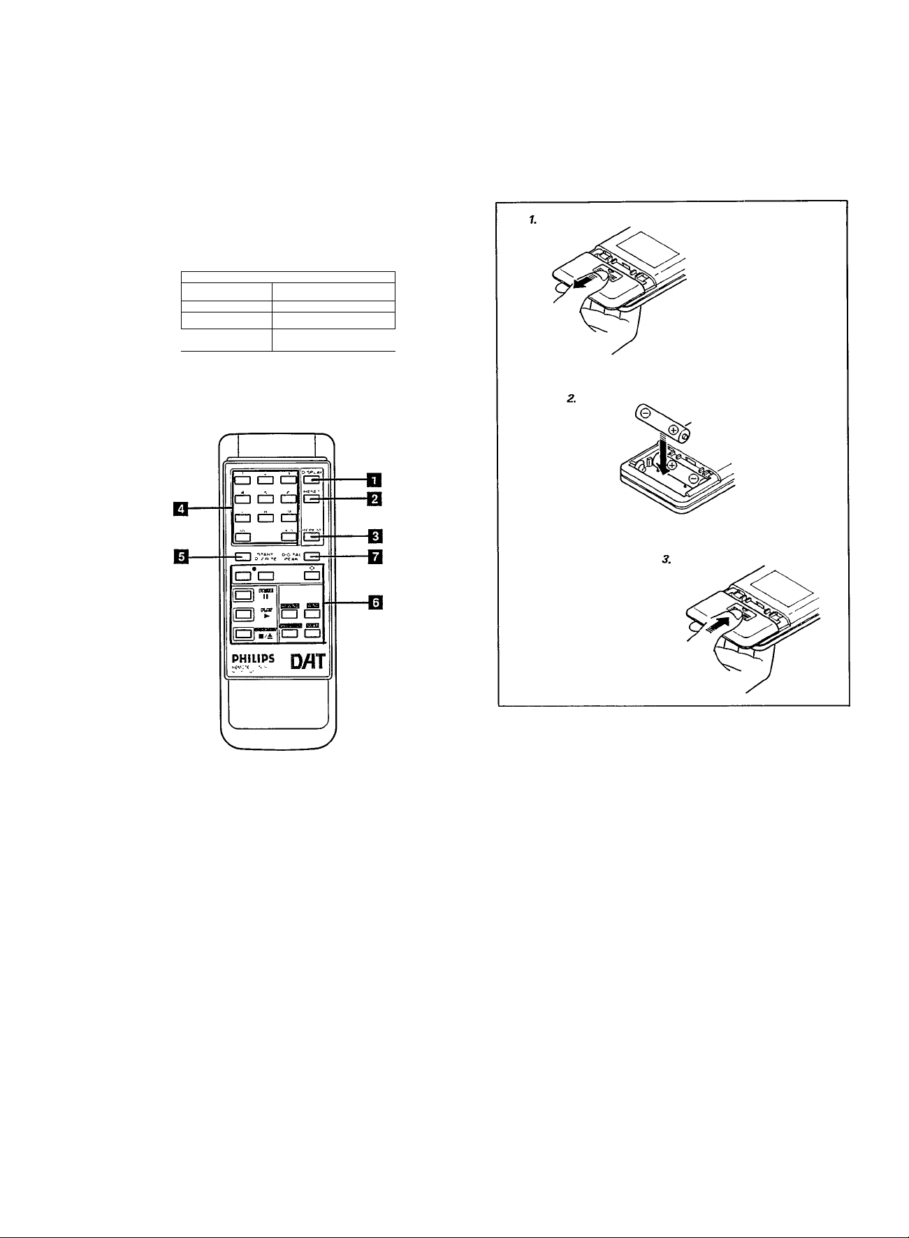
REMOTE CONTROL OPERATIONS
Correct use of the remote control
• Press the button(s) while pointing the top of the remote control
unit at the remote sensor on the front panel of the main unit.
• The operable range is about 7 meters away from the main
unit. If operated at an angle, the range will be shorter.
• Do notallowdirectsunlightorstrong lightfrom afluorescent
light, etc. to strike the remote sensor, as far as possible.
MIUH
---------------------
1 1
1
_____
J---------------------------
— S
. ^i£St=3 caCafi) ^
l“l 1 ■ 1 1 m
CZ7
i=j"
Battery replacement
1. Open the battery compartment cover.
2. Insert two “R03” batteries.
3. Close the battery compartment cover.
Name of parts and their functions
□ DISPLAY button
B RESET button
B REPEAT button
□ Numeric keys (“1” - “10”, “+10”)
Used to designate the desired tune directly.
B START ID-WRITE button
Used to write a start ID.
B Tape operations buttons
B DIGITAL PEAK button
Used to recall or reset the maximum value stored in the digital
peak memory.
* Other control buttons have the same functions as those on
the front panel of the main unit.
*
Notes:
1. When the distance from which the remote control unit is
effective becomes shorter, the batteries are almost exhausted.
Replace the batteries with new ones.
2. Be sure to use two “R03" batteries in the remote control.
Incorrect use of batteries may cause corrosion or an explosion.
• Insert the batteries into the battery compartment with correct
positive © and negative © polarities.
• Do not use old and new batteries together.
• When the unit is not to be used for an extended period
of time, remove the batteries to prevent damage due to
corrosion.
Page 7
CONNECTIONS
• Do not switch the power on until aii connections are completed.
• Insert the plugs firmly: poor contact can cause noise.
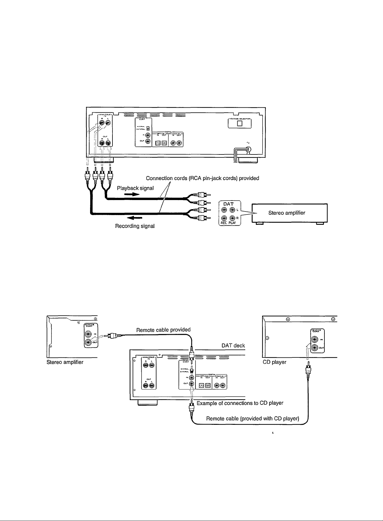
1. Connection to stereo components
(Analog signal lines)
DAT deck
When RCA pin-plug cords are employed, always connect the
white plug to the left channel terminal. This helps avoid
reversed connections.
• When the stereo amplifier is not provided with DAT terminals,
refer to its instruction manual.
2. Remote cable connection for REMOTE
CONT.
• By connecting a remote cable, REMOTE CONT. functions
(synchro recording) can be performed.
' When making synchro recordings with a CD player, connect
the remote cable to the REMOTE CONT. jacks.
Connect the REMOTE CONT. jack of the deck to the REMOTE
CONT. jack of the amplifier using the remote cable provided.
Note:
When installing this unit, leave an appropriate distance between
it and your stereo amplifier, tuner and television set. If they are
too close, noise (induced hum) may occur.
We recommend that you use outdoor FM and TV antennas.
Page 8
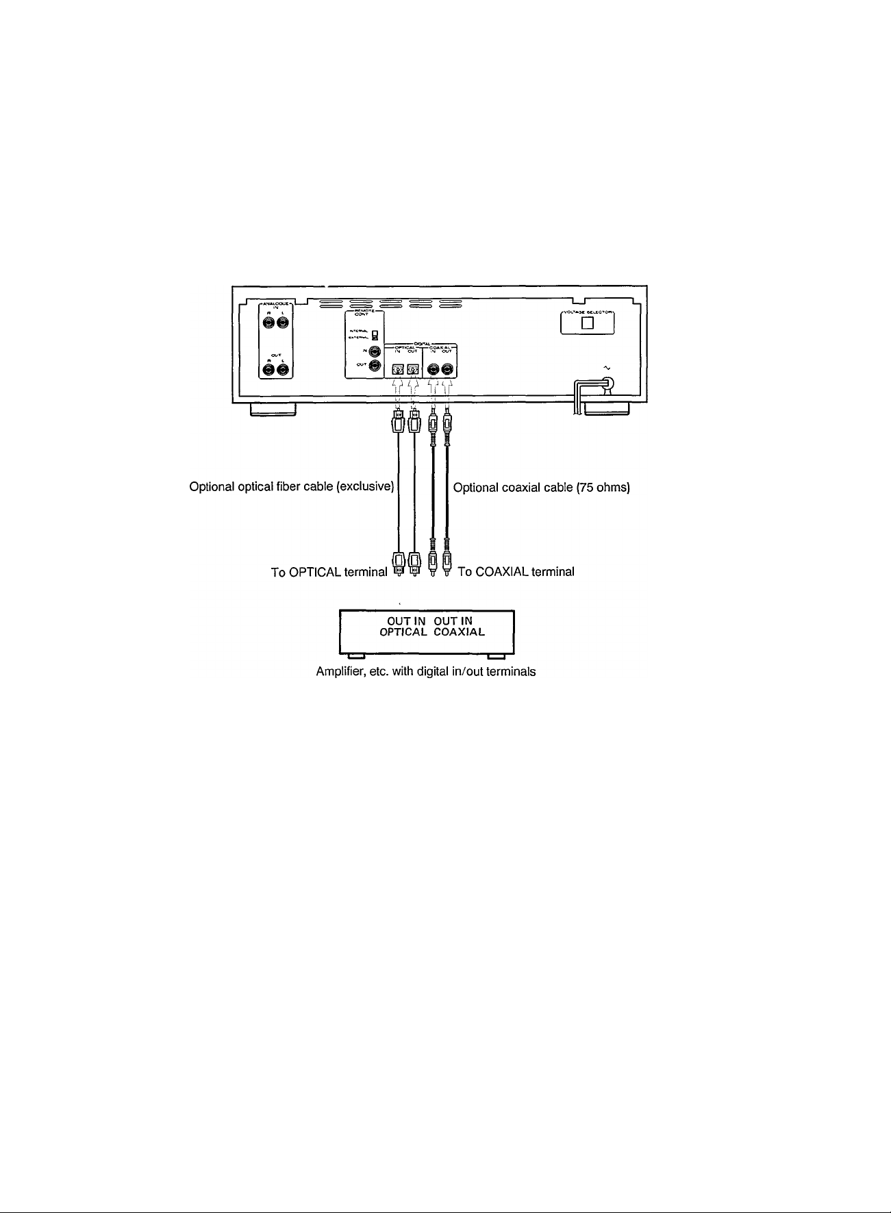
3. Connections to stereo components
(Digital signal lines)
• To transmit digital signais between the DAT deck and an
amplifier with digital in/out terminals exclusively for DAT, use
the DIGITAL IN/OUT terminals on the rear panel of the deck.
For the transmission of digital signals, two types of cables
can be used; COAXIAL (for electrical signals) and OPTICAL
DAT deck
(for optical signals). Either of these can be used for digital
signal transmission.
With digital signals, only one cable is used for the transmission
of both the left and right channel signals.
• OPTICAL connection
Remove the caps from the OPTICAL terminals and connect
the DIGITAL OPTICAL IN/OUT terminals to the amplifier, etc.
using exclusive optical fiber cables.
Note:
Clean the tip of the plug of the optical cable before connecting
it.
• Synchro recording with CD player
When making a synchro recording with a CD player, as well
as connecting the optical fiber or coaxial cable, perform the
following connections.
1. Connect the REMOTE CONT. terminals with the remote
cable. (See page?.)
2. Connect the OUTPUT terminal (analog) of the CD player and
the ANALOG IN terminal wi^i a RCA pin cord.
• Red light in the OPTICAL OUT terminal:
When the power is turned on, a red light appears inside the
terminal. This is used to transmit the digital signal. Although
it is not dangerous even when it strikes the eyes directly, do
not remove the cap covering the terminal when not in use.
Notes:
1. When a digital program is encoded with a “copy prohibit”
code (except in case of SCMS), it cannot be copied
digitally. To copy such a program, perform analog
connection. (Refer to page 12.)
2. Never connect the digital coaxial cable to the analog input
terminals of an amplifier, etc. as this could seriously damage
the amplifier.
3. When the OPTICAL terminals are used for digital connection,
check that the optional exclusive optical fiber cables can be
inserted into the terminals of the amplifier.
4. Do not bend optical fiber cable sharply. For details, refer to
its instructions.
5. When both the ANALOG and COAXIAL terminals of the DAT
deck are used for the connection of certain components
(amplifiers, tuners, cassette decks, etc.), noise (induced hum)
may occur. In this case, disconnect any unused IN/OUT
terminals.
Page 9
DAT CASSETTES
Concerning DAT cassettes
• Use cassette tapes with the DAT logotype shown here.
DgtaiAxtoTape
When a tape on which a recording has previously been made
is used for recording, the previously recorded signals will be
erased automatically, and the tape will contain only the new
recording.
• DAT cassettes cannot be used upside down.
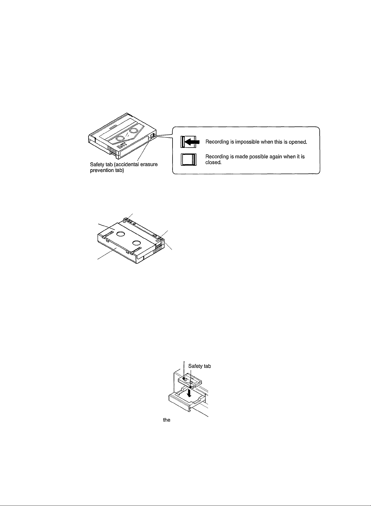
• DAT cassettes have a lid (cover) to prevent the accumulation
of dust or dirt on the surface of the tape. Do not open this
forcibly.
Cassette identification holes x 3
Rear of the cassette
Accidental erasure prevention hole
(determines if recording is possible or not)
• DAT cassettes have sliding safety tabs to prevent accidental
erasure. Be sure to open the tabs of cassettes containing
important recordings which you want to protect against
accidental erasure.
• DAT cassette shells are constructed so that the tape cannot
be touched by accident.
Identification hole (for prerecorded music tapes)
Tape protection lid
Cautions on storage of DAT cassettes
• Do not leave cassettes in a place exposed to direct sunlight
or near a heater, etc.
• Do not leave cassettes in a place subject to excessive humidity.
• Do not drop cassettes or expose them to excessive vibrations
or shocks.
Loading DAT cassettes
1.
L_pi-
1. Set the ON/OFF switch on.
2. Press the mi± STOP/OPEN-CLOSE button to o|
cassette tray.
3. Insert the cassette with its window facing up.
4. Press the ■ / ^ STOP/OPEN-CLOSE button to close the
cassette tray.
2.
STOP-OPÊN/CLOSE
■/A
-fì-
3. With the cassette’s
window facing up
• Do not leave cassettes in a place subject to excessive dust.
• Do not store cassettes where there is a strong magnetic field,
such as near a motor, transformer or permanent magnet, etc.
• When not using them, always replace cassettes in their plastic
cases.
4.
STOP-OPEN/CLOSE
■/A
Page 10

SUB CODES
“Sub codes” are codes recorded on the tape separately from
the music signals. They are mainly used to provided various
functions which make the DAT system more convenient. These
codes are necessary for search operations (direct access
playback), etc.
Types of sub codes and details
Name
Information data
ID (Identification)
Data
A TIME
PRGM NO
START ID
END code
Shows the elapsed recording time
from the beginning of the tape.
(Absolute Time)
Shows the tune number, counting
from the beginning of the tape.
(Program Number)
Indicates the beginning of a tune
Indicates the point at which the
previous recording ended.
Details
Relationship between the music signal and sub
codes
Beginning of tape
Tape
r
------------
Functions
The absolute time is marked
together with the music signal and
allows the elapsed time from the
start of tape to be displayed.
With this code, direct access play
back using the remote control unit is
possible.
Using the AUTO SEARCH buttons,
the beginning of any tune can be
found easily.
When a tape is played back or fast
forwarded, the deck stops automati
cally at the beginning of the End code.
Tape end
1 St tune 2nd tune 3rd tune
Music signal
A TIME
START ID
(marked for 9 seconds from the beginning of each tune)
PRGM NO
(marked for 9 seconds from the beginning of each tune)
PRGM NO
(one tune and one no-signal recorded section)
END code
(marked for 9 seconds at the specified point)
• The sub code recording time shows the time when the tape
is recorded in the 48k, 44k or 32k mode. When recorded
in the 32k-LP mode, the recording time will be doubled.
_r
00000
I n
I
■Lf )-l
No-signal recorded section
20000
(When a 2-hour tape is used for recording in the Standard mode)
n
_______
N01 N0.2 N03
_TL_
N0 2
n_
N03
Note:
When the deck is set to the 32k-LP mode, the A TIME is marked
at half the speed compared with other modes. This is to match
the A TIME and the position of the tape with a one-to-one relation
ship.
« n
(When recorded on blank tape)
(For prerecorded tapes)
J1
10
Page 11

TECHNICAL INFORMATION ABOUT DAT
(Tape Format)
Track width 13.591 yum
^
------------------------------
sub;^j
1
Sub code area
\ A
. A PCM area
ATF area
^ I Tape running direction 8.15 mm/sec
Tape width 3.81 mm
-----
90° with 30 mm dia. head drum (23.501 mm)—^
Direction of head rotation
ATF area
Sub code area
y
SUB
DAT recording system
• In a DAT deck, heads mounted in the head drum rotate at
high speed to record digitally-encoded signals on the tape
at an angle to the tape. This system is called “helical scanning”.
• PCM (music signal) area:
Digitally-encoded music signals are recorded in this area.
• ATF (Automatic Track Finding) area:
This area is used for recording ATF signals which control
the heads so that they trace the recorded signal for accurate
and stable tracking and the correct signals are picked up by
the rotating heads.
• Sub code area:
This area is for recording the signals which enable various
functions such as high-speed search and editing. With the
DAT850, A TIME (absolute time), Program No., Start ID and
End codes can be recorded.
Digital signal processing
• Digital recording in the 48 kHz standard mode
Signals are converted from analog to digital before being
recorded. This is called A/D conversion.
Amplitude
A
Audio (analog) signal
Digital signal JlJnJlJirUlJirir
1. The amplitude of the analog audio signal to be recorded is
detected 48,000 times per second by “slicing” the signal. This
is called “sampling at a frequency of 48 kHz”.
2. The length of each slice is rearranged as 16 data bits. This
is called “16-bit quantization”.
3. Each quantized signal is encoded as a binary number (Os
and 1 s) for digital recording.
• Digital playback
The quantized digital signals recorded on the DAT tape are
reconverted to analog signals through a D/A converter which
performs the reverse operations to those performed in A/D
conversion.
> Time
11
Page 12

SCMS (Serial Copy Management System)
• SCMS controls the DAT’s serial copy with the digital signal.
It is possible for a SCMS-compatible DAT deck to record digital
sources including CDs, DAT prerecorded tapes, DSR (Digital
Satellite Radio) programs onto DAT tape with a direct digital input.
For sources such as CDs, DAT tapes and DSR programs
covered by SCMS regulations, copy-permitted programs can
be recorded on DAT tape whether or not they contain a copyprohibit code. When the copied (recorded) tape is played back
• Copying digital sources
With copy prohibit code
Without copy prohibit code
DSR program
Digital microphone
Whether there is the copy prohibit code or not
Digital copy
----------------
First generation
►
by a DAT deck and the digital output is input to the another
DAT deck, digital recording can be performed if there is no copy
prohibit code, however, digital recording cannot be performed
if there is a copy prohibit code. Namely, one — and only one
— copy can be made of a digital source with a copy prohibit
code, and second-generation, third-generation and serial
copying is not possible. SCMS applies in any DAT mode,
regardless the sampling frequency. The following illustrations
show the principles of the SCMS system.
Second generation Third generation
Separate AD converter
General category
(DSR program)
• Copying analog sources
When an analog signal is input, this signal can be recorded
by a DAT deck because this signal does not contain a copy
prohibit code. However, since the signal recorded on the tape
An A D converter performs sampling and quantization to convert
an analog signal into a digital signal. This signal processing
is called “A'D conversion" and the circuit which performs it
IS called an A D converter.
Digital copy
has passed through the A/D converter (ADC), the tape is
treated as a DAT prerecorded tape which contains the copy
prohibit code.
12
Page 13

RECORDING
Before performing recording:
• Make sure the safety tab of the cassette is ciosed.
• Set the TiMER switch to OFF before switching the POWER
on.
— Operate in numerical order. —
Set the ON/OFF switch to ON.
PHILIPS
«MOTI CC«Ti!5(.UCi C i-’*. A.: D tA)>£ ctcx OATSiO
'
DMT
>
II II ' -I I
Set the TIMER switch to OFF. 0 (6) 0® 0 ®
©Press the B/a STOP/OPEN-CLOSE button to open the
cassette tray.
® Insert a cassette with its window facing up.
© Locate the position from which recording should start with
the SEARCH buttons.
REWIND: When recording is to start from the beginning of
the tape.
WIND : When recording is to start from the middle of the
tape. (The End code is detected.)
©Select the source to be recorded.
ANALOG: When recording analog input signals
OPTICAL or COAXIAL: When recording digital input signals
® Set the deck to the rec-pause mode.
• "SAMPLING MONITOR" lights.
® Select the recording mode. When recording analog signals,
adjust the recording level.
• Recording mode
IBH
It may be unlawful to record or playback copyrighted
material without the consent of the copyright owner.
(only analog recording)
0
Notes:
1. When starting recording at the beginning of the tape, leave
a no-signal recorded section of about 10 seconds.
2. “TOP” is displayed when the deck enters the rec-pause or
rec mode after the tape has been rewound.
Recording level adjustment
(only when an analog signal is to be recorded)
m
I o
I LldB
REC TIME
switch
STD
LONG
©Press the ► PLAY button to start recording.
• When recording a digital signal
The recording level, sampling frequency and emphasis status
are recorded as they are. It is not necessary to adjust the
recording level.
• For details about digital recording, see page 16.
• When the end of a tape is reached
With the auto rewind function, the tape is rewound to its begin
ning and stops automatically.
• Tape protection
When the cassette tray is closed, sometimes it will pop out
again; this is to protect the tape. If this happens, adjust the
position of the cassette and close the tray again.
Analog recording
48k mode
32k-LP mode
Digital recording
32k mode
32k-LP mode
48/44k mode
• Peak level meter and digital peak display:
IT] Peak level meter
Values higher than -40 dB will be displayed for the left and
right channels independently, while peak values are held for
approx. 2 seconds.
in Reference level indicator
Shows the reference input level of the DAT deck at a position
-18 dB from the full-scale level.
rn OVER level indicator
Lights when the recording level is too high.
m Digital peak display
Shows the margin between the maximum input level and
the input level of the signal being recorded in 1-dB steps,
within a range of -19 dB to 0 dB.
13
Page 14

Adjusting the recording level
1.
REC/REC MUTE
•/O
LpiJ
Press the DIGITAL PEAK button on
the remote control unit.
1. Press the i/oREC/REC MUTE button. The deck enters the
sampling monitor mode.
2. Adjust the recording level.
Set the recording level by referring to the digital peak display.
Adjust the maximum value of the recording level so that the
OVER indicator does not light.
3. Check the digital peak level.
• While the previously held digital peak value is blinking, press
the DIGITAL PEAK button again so that the new peak value
is held in memory.
• Sub code marking during recording
In the following case, the A TIME (absolute time). Start ID
and Program No. codes will be marked automatically.
Sub code
A TIME • When recording starts from the beginning of the tape
• When the previously marked A TIME is read and displayed
3.
DIGITAL
PEAK
• Sampling monitor
This is used to check the quality of the source sound before
you start recording, or to check the recording level.
• In the stop mode, press the «/oREC/REC MUTE button ...
• Set the deck to the recording or rec-pause mode...
The SAMPLING MONITOR indicator lights and the source sound
can be monitored.
Condition for automatic marking
MARGIN ¡j
0
The previously held digital peak
value blinks for approx. 5 seconds.
Start ID
• When the signal is input after the level of the input signal drops to a specified level
(no-signal) for more than 3 seconds during recording.
• When the first signal is input immediately after recording starts
Program No. (tune No.)
• When recording starts from the beginning of the tape
• When the previously marked program No. is read out and displayed
• To stop recording
Press the END button so that the End code is marked.
This makes it easy to locate the position where next recording
should be started; the A TIME codes marked in the new
recording are continuous from those marked in the previous
recording.
END/RENUMBER
Notes:
1. If the recording level is set to a value where the OVER level
indicator lights continuously, the recording signal will saturate
the tape and the sound will be distorted. Decrease the
recording level to a level at which the OVER level indicator
does not light.
2. Emphasis
With emphasis, high-frequency signals are recorded after
increasing their level (preemphasis); during playback this
process is reversed (deemphasis). This improves the S/N ratio
at higher frequencies.
This deck incorporates only a deemphasis circuit, so it is
possible to play back signals which were recorded with
emphasis, however, it is impossible to record signals applying
emphasis.
14
Page 15

Record muting Synchronized recording with the CD player
This is used to leave an appropriate no-signal recorded section
between tunes.
1. When a section of the source you do not want to record
is reached during recording, press the «/oREC/REC MUTE
button then release it. The REC indicator blinks and a
no-signal recorded section is left during record muting
operation.
REC/REC MUTE
•/O
0
ffilcl
Blinks
~A—
Press and release it.
• About 4 seconds later, the REC and PAUSE indicators light
and the deck enters the rec-pause mode.
2. Press the ► PLAY button to start recording again.
To leave a no-signal recorded section of more than 4 seconds
Keep the */o REC/REC MUTE button pressed continuously as
long as you want to leave a no-signal recorded section. When
the button is released after the above operations, the deck enters
the rec-pause mode.
• A TIME codes will be written continuously even when the rec-
mute mode is engaged.
• To make recordings in different recording modes on one
tape
Be sure to leave a no-signal section before starting recording
In the new mode.
No-signal recorded sections
are left.
Preparation: Connect the connecting cord to the REMOTE
CONT. jack on the CD player beforehand.
1. Insert the cassette tape. Set the desired starting point of
the tape for recording.
2. Press the i^fo REC/REC MUTE and the n PAUSE buttons
simultaneously to enter "REC/PAUSE" mode.
• The DAT deck should be operated from the stop mode.
3. Set the TIMER switch to PLAY.
4. Press the PLAY button of the CD piayer.
• Recording in the programmed order is possible if the
desired tracks have been programmed beforehand.
On completion of the above procedures, the recording to the
DAT deck starts automaticaliy and the recording is carried
out.
The DAT deck enters stop mode automaticaliy when the paly
of the CD player is over.
Blank search
• This is used to locate the point in the middle of a tape where
the previous recording ended, so a new recording can be
made from that position.
1- Load a cassette and press the WIND button.
REWIND WIND
-Pf
Example: To change the recording mode from 48k to 32k-LP
-----
i> r
1. Set the deck to the rec-pause mode.
2. Change the recoding mode.
3. Press the «/o REC/REC MUTE button.
• After 4 seconds, the deck enters the rec-pause mode. Press
the ► PLAY button to start recording.
Note:
When making a recording, if you change the recording mode
(48k, 44k, 32k or 32k-LP) in the middle of a tape, be sure to
leave a no-signal section using the Record Mute function, etc.
before starting recording in the new mode.
no-signal section
— Start recording from here.
2. When the End code is detected, the deck stops automatically.
r j jg
START ID and program number
The tape is automatically rewound to the beginning of the
End code and stops there.
non-recorded section
End code
\
PRSM KO
EE
• When an End code is not marked, the deck automatically
stops just before the non-recorded section of the tape.
• If new tape is loaded, the tape is first fast-forwarded and
after 5 seconds, the tape is rewound.
15
Page 16

' Non-recorded sections (blank) and no-signal recorded
sections
In DAT decks, a non-recorded section (blank section) refers
to that part of the tape which has not yet been used for
recording; this distinguishes it from a no-signal recorded
section, which has been used for recording but without a music
signal.
Digital recording
• Check whether digital recording is possible or not referring
to the DIGITAL INPUT indicator and the COPY PHBT indicator.
1. Set the SOURCE switch to COAXIAL or OPTICAL and check
the DIGITAL INPUT indicator.
• When the source sound is input..
DIGITAL INPUT indicator Digital signal is input or not
blinks slowly not input
lights
blinks rapidly
input (recording is impossible)
input
In conventional compact cassette tapes, no-signal sections
are left between tunes, however, in DAT cassettes, the track
pattern is encoded and A TIME codes and other signals are
encoded continuously in the sub code area.
Note:
To make a non-recorded tape, adjust the INPUT LEVEL controls
to “MIN”, then start recording. The previously recorded signal
will be erased. New A TIME codes will be written to the tape.
• When the DIGITAL INPUT indicator blinks rapidly, digital
recording cannot be performed. Set the SOURCE switch to
ANALOG to perform analog recording. (The DIGITAL INPUT
indicator goes off.)
2. Check the COPY PHBT indicator in the sampling monitor
mode.
DAT deck mode
during recording
not lit
lights
biinks Only one copy is possible
COPY PHBT
Condition of
the indicator
during sampling monitoring
not lit
blinks
not lit
• If a source cannot be recorded, check the condition of the
COPY PHBT indicator in the sampling monitor mode.
Notes:
1. When you attempt to record a source the digital recording
of which is impossible, the deck enters the rec-pause mode
automatically, and the DIGITAL INPUT indicator blinks rapidly.
2. When digitally recording some CDs, depending on the CD
player used, sometimes the beginning of certain tunes will
be cut or noise recorded. This is because the digital input
signal is unstable and the DAT deck enters the rec-pause
mode automatically when the mode of the CD player is
changed. In this case, perform digital recording as follows:
© Set the DAT deck to the rec-pause mode.
© Locate the position slightly before that from which recording
should start. Now start the CD player.
® Press the ► PLAY button of the DAT deck just before
the required tune.
Status of recorded tape
Further digital copying is possible
Further digital copying is not possible
16
Page 17

SUB CODE MARKING
Automatic Start ID and Program No. code marking
When recording is started from the beginning of a tape, the
Start ID and Program No. codes wiil be marked automaticaliy.
beginning of tape
I’ 1st tune j3 j
Program No. 1
more than
3 seconds
below a certain level (almost
no-signal level)
• When the signal drops below a certain level for more than
3 seconds between tunes, the next Start ID and Program No.
codes are marked automatically.
Notes;
1. When a very quiet sound (such as a pianissimo passage)
continues for a relatively long time. Start ID and Program
No. codes might be marked erroneously.
2. When the gap between tunes is less than 3 seconds, neither
the Start ID nor Program No. codes will be marked.
3. When operating using the remote control unit, the ST-WRITE
button has same function as the START ID button of the main
unit.
J 2nd tune f
Start ID and Start ID and
I Program No. 2 Program No. 3
1 St tune 2nd tune
Marking the End code (Manual)
Be sure to mark the End code when you stop recording in the
middle of a tape.
1. Press the END button at the end of recording.
END/RENUMBER
WRITE
/. I_
/_ /_
□ 0
2. When the End code has been marked, the tape is rewound
to the beginning of the End code and the deck stops
automatically.
non-recorded section
f tune J
Start ID and Program No. codes
Stops automatically when the tape is
played back or is fast-forwarded.
End code
--------------------
tt
Note:
The End code cannot be marked in the stop mode.
Manually marking Start ID and Program No. codes
The Start ID and Program No. codes are marked by pressing
the START ID button during recording when the gap between
tunes or no-signal portions is less than 3 seconds.
Press the START ID button at the beginning of a tune.
r
The Start ID and Program No. codes will be marked.
START ID
• With this operation, manual marking is possible anywhere you
want Start ID and Program No. codes.
• When recording is to start from the middle of the tape, first
rewind the tape to read the Program No. codes which have
already been marked.
Note:
Another Start ID code cannot be marked for 9 seconds after
automatic or manual marking has been started. (When recording
in the 32k-LP mode, this period becomes 18 seconds.)
Marking sub codes after recording
• Outline of operation for marking sub codes after recording
We recommend that sub codes are marked after recording.
Operate as follows:
1. First play back the recorded tape and check that Start ID
codes have been marked correctly at the beginning of each
tune.
2. Delete unnecessary sub codes (Start ID codes).
3. Insert additional Start ID codes at the beginnings of any
required tunes.
4. Mark the Start ID code using the AUTO ID EDIT function.
(See page 19.)
5. Renumber the Program No. codes with the RENUMBER
function. (See page 18.)
• When a Start ID is detected during playback, an indicator
is displayed in the display window. Each time a Program No.
or End code is detected, the PRGM NO changes.
Note:
Marking the sub codes is impossible when the safety tab
(accidental erasure prevention tab) is open. Check that the safety
tab is closed if you want to mark sub codes after recording.
17
Page 18

Deleting sub codes
• To delete Start ID (Program No.) codes
1. Play the tape and locate unnecessary Start ID codes.
PRCMNO
START D
n J - n ■ n o ■ II n
/
u-u J- J LI
Notes:
1. Be sure to mark Start ID codes leaving a gap of at least
18 seconds (36 seconds in the 32k-LP mode).
2. While a Start ID code is being marked, sound may be skipped
at the beginning and the end of the Start ID code; this is
not abnormal.
Start ID indicator
When an unnecessary Start ID is
marked at 9 minutes 30 seconds
2. Press the Start ID erase button while START ID is displayed.
ERASE
PftGMNO
3
Erase indicator
• The tape is rewound and stops at the beginning of the
unnecessary Start ID code.
3. When an unnecessary Start ID code has been erased, the
START ID indicator disappears and the tape stops
automatically.
• The Program No. is also erased at the same time if it has
been marked with the Start ID code.
• Deleting the End code
When recording starts after detecting the End code, the End
code will be erased automatically.
Marking Start ID codes
• This is used to mark Start ID codes at the required points.
1. Start playing the tape and find the point a Start ID code should
be marked.
Example:
When marking a Start ID code at 28 minutes 30 seconds..
PLAY
►
the position of 28 minutes 30 seconds
PRGMNO
A TIME-J -J -J.-,
LI I LI ■ L LI - _/ U
-t-
Marking Program No. codes (Renumbering)
• After marking Start ID codes is completed, insert Program
No. codes at the same points.
1. Press the RENUMBER button in the stop mode.
END/RENUMBER
2. The tape is rewound to its beginning and then Program No.
codes are marked at the points where Start ID codes are
detected, in sequence starting from 1.
When Program No. code 1 is renumbered..
• The numbers shown by the PRGM NO and NEXT NO
indicators are counted up.
3. When the tape reaches its end, this operation is completed
and the tape is rewound to the start automatically.
• When the End code is detected, the deck stops at the beginning
of the End code.
Note:
Renumbering cannot be done during recording. Perform
renumbering in the stop mode.
RENU^eSR
i i NEXT NO ^
LIU L1 I
R£NUS©ER P%MNO
n /recTNor; ^
2. Press the START ID button.
START ID
START ID WRITE A TIME . -f
PRGMNO
U I U ■ C O • D U
-A
Indication while marking the Start ID Recorded from an absolute time
code (when the Start ID code has 28 minutes 30 seconds
been encoded)
3. When marking is finished, the “START ID WRITE” indicator
goes out.
Repeat the above procedures l. through 3. to mark all required
Start ID codes.
18
of
Page 19

AUTO ID EDIT operations
This function is to re-iocate Start ID codes which are being
marked slightly after the beginning of a tune by the Start ID
marking function.
Start ID codes are re-marked from 0.5 second before the
beginning of the tune.
With this function, the beginning of any tune can be located
more accurately.
1. Play back the tape and press the AUTO ID EDIT button at
the point from which the Start ID code is to be remarked.
AUTO ID EDIT
The tape is stopped and is
then rewound to the point
6 second before.
The presence of a music signal is
judged at the -60 dB level. If a blank
space is not detected, the level at
which judgement is performed
becomes -50 dB or -40 dB.
fJTAfillO
--------------------------
n 1 r n 1
U 1 o u o
1^
-1 -75 i H$ -1 -OJ
7
,
_______
D
0 OS
j-JTJOCC
1 see *1-10 POStnON
PKM NO
T
The point at which Start ID codes
are marked is adjusted in steps of
0.25 seconds
• The appropriate Start ID code marking point is..
signal level (tune)
-------
►---------------
the point where the signal level
rises to over -40 dB
no-signal level /^/st^ ID (already marked) This is
(below-40 dB) [ marked slightly after the beginning
of the tune
0.5 second
With the AUTO ID EDIT function,
the Start ID code is marked
0.5 second before the beginning of
the tune. This is a more appropriate
point.
2. When the appropriate point is detected, the ID POSITION
indicator blinks.
Example:
Indication when a signal of above -60 dB is recorded
^TAAT ID
NO
LI I
-i *7$ 7 -ti *1 -0?
- P n J
O U O
1
==.L=,=_ J--''««
1 TA«
Cir-
0 ”1-10 P0$1TICN
Indication of the most appropriate Indication of the recorded
marking point Start ID code
3. Press the START ID button.
START ID
• The START ID WRITE indicator lights and the Start ID and
Program No. codes are re-marked.
• When remarking is complete, the deck stops automatically.
• The appropriate marking point is also detected if the AUTO
ID EDIT button is pressed in the stop mode.
• The JUDGE indicator lights when the tune is found.
• To move the Start ID code marking point..
Press the PREVIOUS or NEXT button while the ID POSITION
indicator is blinking.
Every time this is pressed, the Start ID
code is moved backward in steps of
0.25 seconds, (up to 3.5 seconds)
c
1
Every time this is pressed, the Start ID
code is moved forward in steps of 0.25
seconds, (up to 1 second)
• When all of the JUDGE indicators light and “0” blinks in the
ID POSITION indicator.
This indicates that an appropriate marking point below -40 dB
cannot be found. Repeat operation 1. again.
Notes:
7, To cancel the AUTO ID EDIT function while it is operating,
press the ■ STOP or ► PLAY button.
2. When no tune is detected, the JUDGE indicator will not light.
3. When a tape on which A TIME codes have not been marked
is loaded, this function will not work.
4. When a section with a no-signal level (below -40 dB) cannot
be detected, mark the Start ID code referring to “marking
Start ID codes” on page 18.
s. Start ID codes are marked and shown by the ID POSITION
indicator in steps of 0.25 seconds. They could sometimes by
delayed if the AUTO ID EDIT button has been pressed.
19
Page 20

PLAYBACK
— Operate in numerical order. —
Before starting operation, set the TIMER switch to OFF.
Set the ON/OFF switch to ON.
r HILIPS
REMOT« ««TROute cas.r*i TAJ>£ CCCK DAT8W
DAI
Set the TIMER switch to OFF.
©Press the ■/^STOP/OPEN-CLOSE button to open the
cassette tray. (See page 9.)
® Load a cassette with the window of the cassette facing up
and close the tray.
® Press the ► PLAY button. Playback will start.
• The sampling frequency is displayed in the display window.
• When a tape is played back to its end...
The auto rewind function rewinds the tape to its start at which
point it stops automatically.
• To stop playback in the middle of a tape..
Press the ■ STOP button. Press it again to open the cassette
tray.
• If the EMPHASIS indicator lights..
When the tape is reached a position where emphasis is applied,
high-frequency signals are deemphasized automatically by
the deemphasis circuit.
• If a tape recorded in 32k-LP mode is played back..
The 32 kHz and “LONG PLAY” indicators light in the display
window.
• To fast-forward or rewind the tape so you can hear the
speeded-up sound at a lower volume..
Press the REWIND or WIND button during playback. The
tape advances at 3 times normal speed.
c
To cue to a tune in the reverse
direction (review function)
1
To cue to a tune in the forward
direction (cue function)
0
®
AUTO SEARCH buttons
/
0
Notes:
1. If the End code is detected while the tape is being played
back or fast-forwarded, the tape stops automatically. Press
the REWIND button and rewind the tape.
2. If a new tape is played back, the tape is rewound to its start
within 10 seconds.
3. If the non-recorded section of a recorded tape is played back,
the tape is rewound to the end of the last tune within
10 seconds and stops automatically.
4. During high-speed playback, at the point where the mode
was changed in recording, sound might not be heard. In this
case, first perform normal playback and then set to the fastforward or rewind mode.
• When playing back a tape you have recorded yourself
(recorded on blank tape)
• When the cassette Is loaded..
• If A TIME codes have been marked on the tape, they are
detected and displayed in the display window.
• When a rewound tape is loaded, first (— 00:01) is displayed
and then the A TIME code is displayed.
• Program Nos. will be displayed when they are detected.
• When no Program No. is displayed in the PRGM No.
display:
Program No. codes are marked at the beginnings of tunes
together with Start ID codes. If the cassette is loaded/
unloaded in the middle of a tune and if a Program No. code
has not been marked at that point, no Program No. will appear
in the display. To display the Program No. in this case,
continue playback or set the deck to the fast-forward/rewind
mode so that the Program No. code is read out.
When the button is released, normal playback will resume.
20
Page 21

Auto repeat
This is used to piay back tunes you want to iisten again.
Playback using Start ID codes
To find the beginning of the previous tune..
REPEAT
Every time the REPEAT button is pressed, the foiiowing
indications are dispiayed.
ALL: aii tunes are repeated
1: the current tune is repeated
3
[ÀÌTI [T]
I—
RFPFAT—
(Auto repeat function is canceiied.)
I
ii:zz3 goes off <iJ]
l—RFPFAT—
I
Direct access playback
Playback with program No. codes (can only be performed
using the remote control unit)
tune number buttons
When designating Program Nos. 1 to 10.
indicator biinks
1
When the PREViOUS button is pressed three times, the tape is
rewound to the beginning of the tune 2 before the current tune.
• Every time this is pressed, the start of the previous tune is
detected.
To find the beginning of the next tune..
When the NEXT button is pressed twice, the tape is fast-forwarded to the beginning of tune after next.
• Every time this is pressed, the start of the next tune is detected.
• When the Start ID code of the required tune is detected,
playback starts.
Notes:
1. Tapes on which Program No. codes have not been marked
cannot be used for this operation if designating is performed
using the tune number buttons.
Tapes on which Start ID codes are not marked cannot be
used for this operation using the PREVIOUS/NEXT AUTO
SEARCH button.
^ _ _^]
NEXT NO
indicator biinks
NEXT NO
\ RaTI
. 'll 1
• LI L
-----------
I I j—
2. When the ll PAUSE button is pressed while searching, the
deck enters the pause mode after locating the desired tune.
C±) C±1 C±]
C±l C±] C±]
□ l±l (±
O □(
Press the Program No. button corresponding to the number
of the tune.
• When designating tune No. 11 or higher..
Designate the required tune No. by pressing the +10 button
and a Program No. button. (When the +10 button is pressed
once, the “NEXT NO -1 ” is displayed.
example: when designating 24
♦10 *10 A
CZl (ZIl
example: when designating 30
♦IQ ♦IQ 10
CZ] -► CZI CD
• When the program No. code of the required tune is detected,
playback starts.
21
Page 22

DIGITAL DUBBING
— Operate in numerical order. —
Connection (COAXIAL connection)
When two DAT850 DAT decks are used together, digital dubbing
of tapes is possible.
Recording DAT deck Playback DAT deck
Set the SOURCE switch to the
COAXIAL position.
• Operations
Operation of recording deck
Load a blank DAT cassette.
• Check that the safety tab of the cassette is in place.
1
• When dubbing from the middle of the tape, the deck
should first read out the A TIME and the Program No.
codes.
Set the SOURCE switch to “COAXIAL”.
3
• The DIGITAL INPUT indicator lights in the display
window.
Set the REC TIME switch to the recording mode.
4
• 32k mode... STD
• 32k-LP mode ... LONG
Set the deck to the record mode from the rec-pause
5
mode.
• When Start ID codes have been encoded on the tape
from which dubbing is to be performed, they will be
copied to the new tape.
• The signal on the new tape will be at the same level as
that on the tape from which dubbing is performed.
• When an OPTICAL cable is used for connection:
When using an optical digital cable, connect the OPTICAL
IN terminal of the recording deck to the OPTICAL OUT terminal
of the playback deck, and set the SOURCE switch to the
OPTICAL position.
• If the tape speed (recording mode) has been changed in the
middle of the tape being dubbed, dubbing is interrupted, the
deck is set to the rec-pause mode and then the dubbing
operation resumes.
• In digital dubbing, the copy has the same sampiing frequency
as the source. The recording mode cannot be changed using
the recording deck’s controls.
•
Operation of playback deck
Load the DAT cassette from which dubbing is to be
performed.
2
• When dubbing the tunes in the order in which they
were recorded, the program number should be
displayed.
Press the ► PLAY button to start the dubbing operation.
6
Sampling frequency of the
playback tape
48 kHz
44.1 kHz
32 kHz
Notes:
1. Use either the COAXIAL connection (coaxial cable) or the
OPTICAL connection (optical digital cable) for digital
connection.
2. When a tape with a digital copy prohibit code is loaded, the
DIGITAL INPUT indicator blinks rapidly. In this case, the deck
cannot be set to the record mode.
3. If the COPY PHBT indicator blinks when a tape is being played
back, digital dubbing of the tape is impossible.
Sampling frequency of
the recorded tape
48 kHz
44.1 kHz
32 kHz
22
Page 23

TIMER RECORDING AND PLAYBACK
• When an optional audio timer is used together with the deck,
recording and playback can be started at the desired time
(when you are not at home, etc.)
• When an audio timer which can perform repeated ON/OFF
switching is used, repeated recording and playback can be
performed.
• Connection to audio timer
Set the POWER switches of all components to ON.
0
To a wall AC outlet
-----------------------------^ 1_1
Set the ON/OFF switch ON.
HIUH _ ... ... . 2
i 1,. r/,. n
f
1—j
a^c3
■ 1 . 1 .1 ■ J 0 ®
L —J
TIMER switch
• Refer to the instruction manual of the audio timer used before
starting timer recording/playback.
• A DAT cassette with its safety tab open cannot be used for
recording.
Audio timer section
------------------------------1_
To the AC outlet of audio timer
i '
Note:
This diagram does not represent a U.K. mains plug.
Operation procedure
1. Timer operations • Check that the POWER switches of all components connected to the timer are set to ON.
Timer recording Timer playback
• Operate the timer so that it turns on the power to each component.
2. Amplifier/tuner operations
• Tune to the required broadcast.
FM broadcast: TUNER
DSR broadcast: LINE
• Set the TAPE MONITOR switch of the
amplifier to ON.
• Adjust the volume with the amplifier’s
volume control.
3. Deck operations
• Load the cassette on which the recording is to
be made and operate for recording. (Refer to
• Load a prerecorded cassette and operate for
playback. (Refer to page 20.)
page 13.)
4. Timer operations • Program the timer’s ON time for when recording/playback is to start and
its OFF time for when it is to stop.
• When programming the timer’s ON time and OFF time, allow a margin of 1 minute for each.
• Check that the power supplies of all components connected to the timer are turned OFF.
5. Deck operations • Set the TIMER switch to the REG position.
[1 1 "n 1^
REC OFF PLAY
TIMER
• Set the TIMER switch to the PLAY position.
1 i|
REC off' play
TIMER
Recording will start when the preset time is
reached.
Notes:
1. After timer recording/playback has finished, be sure to set
the TIMER ON/OFF switch of the DAT deck to its OFF position.
Playback will start when the preset time is
reached.
2. After recording to the end of the tape in timer recording, rewind
the tape with the REWIND button.
23
Page 24

TROUBLESHOOTING
What appears to be a malfunction may not always be serious.
Make sure first..
1. Deck does not function when any buttons are pressed.
* Is a cassette loaded?
* Had 5 seconds elapsed after the power was turned ON?
2. Playback (recording) starts when the power is turned ON.
* Is the TIMER switch set to PLAY(REC)?
3. Recording is impossible.
* Is the safety tab of the cassette open?
4. Tape does not run.
* Has the ll PAUSE button been pressed?
5. Playback sound is not output even although the tape
runs.
* Is the volume control set to its minimum position?
6. Direct access playback cannot be done correctly.
* Are Start ID codes marked on the tape?
* Have adjacent Start ID codes been marked within 18
seconds of each other (36 seconds in the 32k-LP mode)?
7. Recording of digital input signal is impossible.
* Has the SOURCE switch been set to ANALOG?
’ Does the COPY PHBT indicator light in the sampling
monitor mode?
8. Cassette cannot be loaded. (Cassette is unloaded
immediately after it is loaded.)
* Is the tape damaged?
9. Recording cannot be done correctly.
* Are the heads dirty?
10. Program No. does not change when the tune changes.
* Did recording start from the middle of a tape which was
previously used for recording?
11. Tape does not run even though the ► PLAY button is
pressed.
* Has a non-recorded tape been loaded?
12. Deck is not operated with the remote control unit.
* Has the remote control switch on the rear panel been
set the EXTERNAL?
* Set the remote control switch to iNTERNAL
• If the deck or tape malfunctions, the recording may not be
performed correctly.
• We recommend that you make a test recording before making
an important recording.
24
Page 25

SPECIFICATIONS
Basic format
Operation modes used:
Recording/playback mode
48k
Tape speed
(mm/sec)
Recording/
playback time
(R-120)*
Sampling
frequency
Number of bits
quantization
8.15 8.15
120 min. 120 min.
48 kHz 44.1 kHz
16-bit
linear
Number of channels
Frequency response
Signal-to-noise ratio
Dynamic range
Total harmonic
distortion
Wow & flutter
Access time
Fast forward/rewind
time
Error correction
system
Input/output
terminals (Analog)
Conforming to R-DAT format proposed
by the DAT Conference, SCMS
compatible DAT deck
Playback
only mode
44k 32k
8.15 4.075
120 min. 240 min.
32 kHz 32 kHz 44.1 kHz
16-bit
linear
16-bit
linear
32k-LP
12-bit
non-linear
44k-WT
12.225
80 min.
16-bit
linear
2 Channels, stereo
2 Hz — 22,000 Hz ±0.5 dB (48k mode)
2 Hz — 20,000 Hz ±0.5 dB (44k mode)
2 Hz — 14,500 Hz ±0.5 dB (32k/32kLP mode)
92 dB (48k mode recording/playback)
94 dB (48k mode recording/playback)
0.003% (1 kHz, 48k mode recording/
playback)
0.08% (1 kHz, 32k-LP mode recording/
playback)
Less than measurable limit (±0.001 %
W.PEAK)
5 minutes access time; 8.0 seconds
60 minutes access time; 31.3 seconds
Approx. 52 seconds (R-120 cassette)
Doubly-encoded Read-Solomon Code
LINE IN (RCA jack) X 2
Min input level; 63mV (500mV at full
scale)
Input impedance ; 47 kohms
LINE OUT (RCA jack) X 2
Output level; 0.25V (2V at full scale)
Output impedance; 200 ohms
PHONES (6.3 mm dia. standard phone
jack) X 1
Output level; 0 — 0.1 mW/8 ohms
(6.3mW/8 ohms at full scale)
Matching impedance; 8 ohms —
1 kohms
Input/output
terminals (Digital)
; COAXIAL IN (RCA jack) x 1
0.5Vp-p Input impedance; 75 ohms
OPTICAL IN X 1 ; -27 dBm —
-14 dBm
COAXIAL OUT (RCA jack) x 1
0.5Vp-p Output impedance; 75 ohms
OPTICAL OUT X 1 ; -21 dBm —
-15 dBm
Other terminals
Power requirements
Power consumption
Dimensions (WxHxD)
Weight
Accessories
: REMOTE CONTROL (Pin jack) x 2
: AC 240/220/120V, 50/60HZ
; 24 watts
: 420 x 129 X 336 mm
: Approx. 6.6 kg
: RCA-plug connection cord x 2
Remote cable x 1
Remote control unit (RC850DAT) x 1
Battery (size “R03” for remote control
operation) x 2
• Only digital recording is possible in the 44k and 32k modes.
* R-120 is a DAT cassette with a recording time of 120
minutes in the Standard mode.
Specifications subject to change without prior notice.
This product complies with the radio interference requirements
as laid down in ECC (European Economic Community) regulations.
Important note for users in U.K.:
The U.K. version is not fitted withp mains plug.
When fitting a mains plug to the mains lead note that the vnres in the mains lead are coloured with
the following code:
Blue 55 Neutral, Brown = Live.
As these colours may notcorrespond with thecolour markings identifying the terminals inyourplug
proceed as follows: the Brown wire must be connected to the terminal v/hich is marked with the
letter L or coloured Red.
The Blue wire must be connected to the terminal v\hich is marked with the letter N or coloured
Black.
Note: This apparatus must be protected by a 3 Amp Fuse if a 13 Amp plug is used or, if any other
type of plug is used, by a 5 Amp Fuse either in the plug or adapter or a( the distribution board, if
in doubt consult a qualified electrician.
DO NOT CONNECT EITHER WIRE TO THE EARTH TERMINAL IN THE PLUG WHICH IS
MARKED BY THE LETTER E OR BY THE SAFETY EARTH SYMBOL OR COLOURED GREEN OR
GREEN - AND - YELLOW
25
Page 26

(a)(5) © @
<© © (9) (5)0 (I)
ftENUMBEft PRO NO
■ SIARriD'MlTE'l A TIME
erase! / / / / NEXT //*// I I
-dB 60 50 AO 30 26 23 20
EXD =>=='====
m
-3S -3 -25 -2
18 16 lA »2 »0
(© cb
© ©
:fRE3 Fuwl tPAusei i.__P!G.!TAi. INPUT ! rnpcn
.—I •—i” r r I rfppat i
LI u . u u • U L/
© (n) (o)
IA£tSiM£pyCiWDt£^ I RFPPaT I
¡A8JsH2_AA15{£1<^ I CONGPIAY I-
>C0Pr PHSTI |EMP»^a
6 A 3 2
j-JUDGE
margin/,g—
L|d position
® o®
®
l_J"
® ®
© ® ©
i.'oi.TAoe seuECTo«'
©
118
Page 27

Page 28

013W851313
 Loading...