

PHILIPS CTN – BB Service Manual
Mechanical and electrical parts list
CTN-BB CHASSIS
ANNEX 2 TO
SERVICE MANUAL
CTN-BB
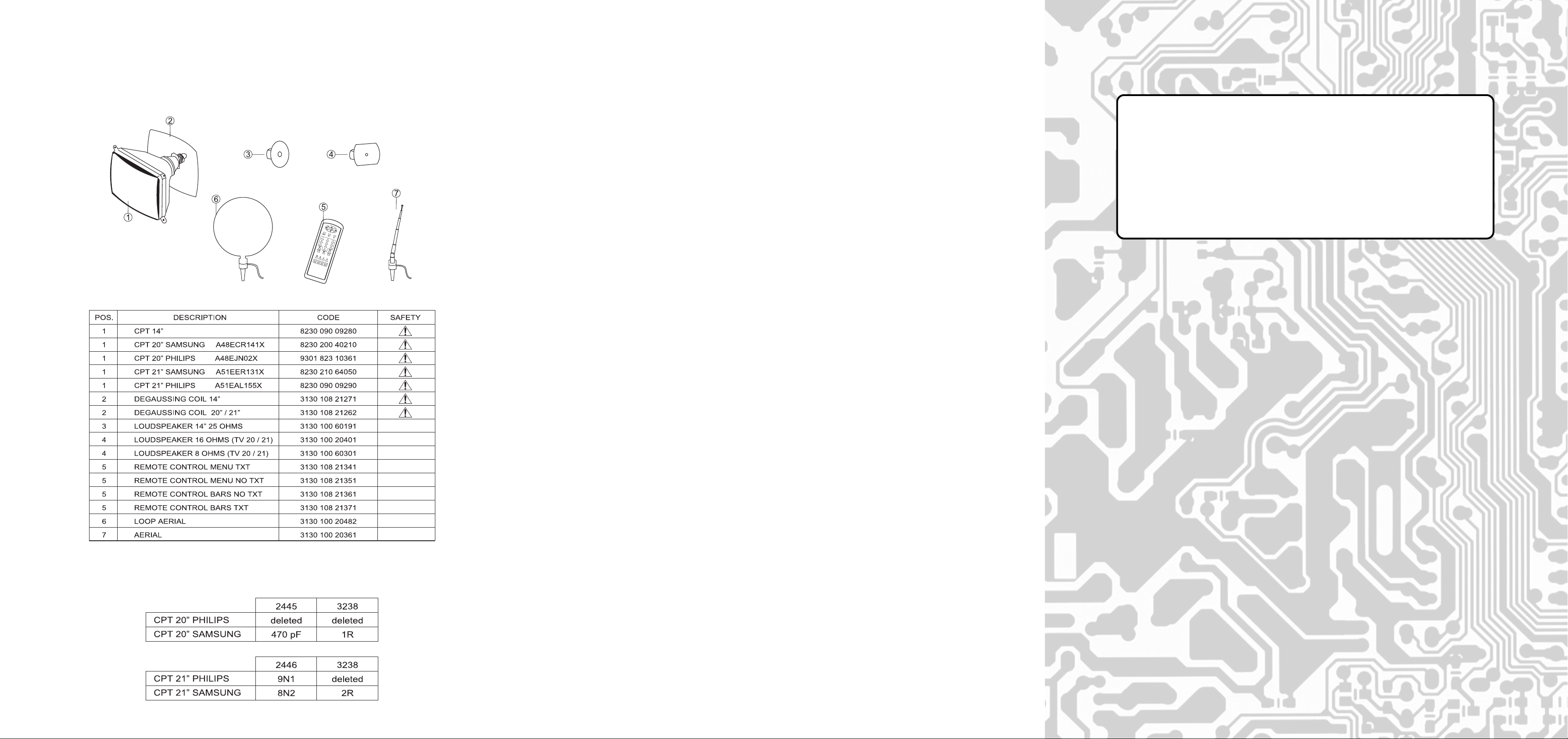
Philips CPT 20”/21” can be replace by Samsung CPT 20”/21” or vice versa, modifying components (supplied together
with CPT a Kit) according the following table.
18
This supplement refers to change of Microprocessor for Circuit Reference 7600.
Chassis type is changed from CTN to CTN-BB.
3130 105 2423.1

Contents Page
Mechanical Parts List
Introduction 2
Circuit Diagrams 3 - 6
Print board layout 7 - 8
Circuit Description
Small signal processing 9 - 10
RBG Amplifiers 11
Sound Circuit 11
Power Supply 12 - 13
Deflection 14
Microcontroller/Text 14 - 15
Service components 16 - 17 - 18
CTN-BB CHASSIS
Introduction
The main change on this Chassis to the previous CTN-AA type are the introduction of
new Microprocessors for both - T ext and Non Text Models.
Also the Flyback Transformer for 20″ ONL Y MODELS has been changed.
The relevant Circuit Diagrams and PCB Layouts have been amended to show these
changes, plus minor corrections/updates have been made to all other circuit information
where this has been found necessary .
Page 16, 17 and 18 shows different Part Numbers for the Component changes on the
new chassis.
Please use the original CTN Service Manual for all other parts information.
**
TV MODELSCREENPOSITION
*
COLOUR
NG-BLACK
BL-WHITE
GR-GREY
MA-IVORY
GO-DARK GREY
VE-GREEN
RS-PINK
RJ-RED
AZ-BLUE
PL-SILVER
HOW TO ORDER
EXAMPLE: FRONT CABINET OF TV700TX COLOUR BLUE:
2
A * 14 * TV700TX * AZ
17

PRINT BOARD LAYOUT
CIRCUIT DESCRIPTION
1.- SMALL SIGNAL PROCESSING (Diagram A)
The small signal is processed by TDA8361, (TDA8360 no scar t) for Pal sets and TDA8362 for Pal/Secam
sets (IC 7015), including IF detection, video processing, chroma decoder , RGB processing, sync processor
and FM sound decoder.
1.1- IF detection (IC7015/6A)
- IF input (pins 45,46): The IF signal comes from pin 11 of the tuner to the IF SA W (Surf ace Acoustic Wa ve)
filter (1015) and the IF-detector IC7015/6A (pins 45 and 46).
- IF filter (1015): The IF bandpass characteristic, determined by the SA W filter, is 33.4 to 38.9 MHz. for BG
sets, 33.5 to 39.5 MHz. for PAL I sets and 32.4 to 38.9 MHz. for DK sets.
- IF oscillator (pins 2,3): Carrier frequency, present in coil L5040, is tuned at 38.9 MHz. for BG sets or
39.5 MHz for Pal I sets
- A GC voltage (pin 47): The AGC delayed voltage is applied to pin 1 of the tuner. It should be adjusted
for 1mV. antenna signal by means of R3021 (pin 49).
- AFC signal (pin 44): The Automatic Frequency Control is obtained from the reference signal of the IFdetector. C2037 smoothes the AFC voltage.
- Identification (pin 4): The identification output is applied to pin 16 of the µC. This signal is high in case of
signal detected.
- Video output (pin 7) : This baseband CVBS signal with 2Vpp of nominal amplitude, also contains the FM
intercarrier sound signal. Sound is filtered out by a ceramic trap (1032 or 1033) which frequency can be
different depending on the system: 5.5 MHz. for BGLL’, 6.0 MHz. Pal I or 6,5 MHz. for DK.
Multistandard sets
-The IC TDA8362 changes automatically between negative (BGIDK) and positive (LL’) modulation.
The IC also determines if the AGC circuit should control at the top white level of the video (positive
modulation) or at the top sync level (negative modulation).
-Saw filter (1015) bandpass characteristic is modified by BG/L switching signal proceeding from the
microcontroller:
- For BGIDK reception BG/L is low, D6014 does no conduct and the bandpass filter is tuned by
5012 and 2013 at 32.9MHz. to 38,9 MHz.
- For LL’ reception BG/L is high, D6014 conducts and so the bandpass filter is tuned by 5012 and
C2014 at 32.4 to 38.9 MHz.
-Oscillator frequency is controlled by the L/L’ switching signal:
-For BGIL reception L/L’ is low, D6042 conduct and so coil 5043 is connected in par allel to 5040.
- The circuit is tuned to 38.9 MHz.
- For L’ reception L/L’ is high, D6042 does nor conduct and the circuit is tuned to 33.4 MHz. by L5040 only.
1.2- Source select, luminance and chroma separation (IC7015/6B)
- Source select (pin 13, 15, 16): The internal CVBS signal is now fed to pin 13 IC7015/6B . External CVBS
from the pin 20 of Euroconnector is present on pin 15. The source selector switch between internal (pin 16 = 0V.)
or external (pin 16 = 8V.).
- Luminance and chrominance separation: Chrominance signal is filtered out (-20dB) by a luminance
notch filter which is internally calibrated at the subcarrier frequency (4.43MHz).
1.3- Chroma Decoding (IC7015/6C)
Pal or Secam signals are recognized automatically by the IC. For Pal signals decoding is made in IC7015/
6C and for Secam signals in IC7250 (TDA8395).
- Pal signal: This signal is amplified and demodulated. The 4.43 MHz. reference crystal for chrominance
demodulation is present at pin 35 of IC7015/6C. The R-Y and B-Y out-puts (pins 30, 31) are applied to
chroma delay line IC7221 (TDA4665).
- Secam signal (pin 27): This signal is applied to pin 16 of Secam decoder IC7250.
- Secam reference (pin 32): Pal or Secam signals are recognized using a DC level by bi-directional
communication line between this pin and pin 1 of IC7250.
-If IC7015/6C has detected a Pal signal, Vpin 32 is made 1,5V. By then the demodulated R-Y and BY outputs (pins 30, 31) are applied to delay line IC7271.
-If IC7015/6C has not detected a Pal signal, Vpin 32 is made 5V. By then the demodulated R-Y and
B-Y at outputs (pins 30, 31) are not used.
-If IC7250 has detected a Secam signal, Vpin 1 IC7250 becomes low, sinking typical 150µA. current
from pin 32 (5V.) of IC7015/6C, which one detect this current to know that a Secam signal has been
detected. In this case R-Y and B-Y signals are applied to the delay line IC7271 via outputs of
IC7250 (pins 9 and 10).
This bi-directional communication line uses AC level to calibrate the 4,43MHz. between the PLL and chroma
cloche filter of IC7250.
1.4- RGB-dematrixing(IC7015/6D)
- R-Y, B-Y inputs (pins 28, 29): The R-Y and B-Y signals come from delay line (IC7271) and the Y signal
comes (internally) from IC7015/6B.
The sandcastle pulse coming (internally) from the IC7015/6E (pin 38) synchronizes RGB dematrixing and
suppresses the RGB signals during line and frame flyback.
- Video controls (pins 17, 25, 26): These inputs for contrast, brightness and saturation can be adjusted
from 0,5V to 4,5V by the µC. If beam current is limited reducing contrast with D6289 circuit.
- RGB inputs (pins 22, 23, 24): External RGB inputs come from Euroconnector and are switched by fast
blanking.
- Fast blanking (pin 21): When voltage of pin 21 is 0,4V. internal RGB is used. For a pin 21 v oltage between
0,4V. and 3,5V. the set switch to external RGB.
If voltage of pin 21 is 4V. both internal and external are deleted. The up uses this status to insert RGB signals
from OSD generator directly to RGB outputs.
Fast blanking can switch signals for full screen (by a DC voltage) or for a part of the screen (by a pulse
voltage).
- RGB outputs (pins 18, 19, 20): See RGB amplifier.
1.5- Horizontal synchro (IC7015/6E)
- Start up (pin 36): When the set is switched on, v oltage at pin 36 rises and when exceeds 7V. the horizontal
oscillator starts running at approx. 25 KHz. (slow start). After the line starts, main supply of IC7015 (pin 10)
comes up to 8V. and the line frequency changes to 15625 Hz.
- Standby (pin 36): This pin is used also for standby function. In this case the voltage is reduced to 3V. by
the uP and so the line is shut down.
- Hor . oscillator: This oscillator is fully integrated and internally calibrated. F requency is obtained derived of
chroma oscillator on pin 35 of IC7015/6C.
- Hor . sync separator: This circuit (fully integ rated) separates hor . pulses of CVBS proceeding from 7051/6B .
- Oscillator synchro (pin 40): Oscillator is synchronized with video signal by a first control loop circuit. The
control voltage is present at pin 39.
- Hor . phase control (pin 39): Line fly-back (pin 38) is synchroniz ed with oscillator by a second control loop
circuit. The control voltage is present at pin 39. Phase can be adjusted by 3354.
- Hor. output (pin 37): Oscillator is converted in square wave voltage at this pin.
- Sandcastle (pin 38): This pin is used as line fly-back input and also as sandcastle output. Levels of
sandcastle pulse are 5,3V for burst detection, 3V. for line blanking and 2V. for frame blanking.
1.6- Vertical synchro (IC7015/6E)
- Vertical oscillator (pin 42): Frequency is obtained dividing frequency of chroma oscillator on pin 35
IC7015/6C. At pin 42 a sawtooth signal is present. Resistor 3342 is used to correct vertical amplitude with
beam current.
- Vert. sync. separator: It separates frame sync. pulses from CVBS and so synchronizes frame oscillator.
- Vert. drive (pin 43): This out-put is used to drive the vertical amplifier (7400)
- Vert. f eedbac k (pin 41): this feedback is proportional to deflection current and is used to correct the vert.
drive signal.
8 9
10
 Loading...