

Page 1

Philips Lighting North America Corporation
200 Franklin Square Drive
Somerset, NJ 08873, USA
Phone: 855-486-2216
www.philips.com/luminaires
Philips Lighting Canada Ltd.
281 Hillmount Road,
Markham ON, Canada L6C 2S3
Phone: 800-668-9008
www.philips.com/luminaires
9140053520 February 2016
WARNING – Shut off AC power to branch
circuits to which units will be connected. All
wiring should be per N.E.C. Articles 501-4(b)
and local codes.
To maintain warranty, equipment with batteries
must be installed or placed on charge within
prescribed period after shipment.
Symmetry Unit Equipment
6 and 12 Volt
18 to 72 Watt
120/100V 50/60Hz
Service Questions Call: 910-259-1000
IMPORTANT SAFEGUARDS
When using electrical equipment, basic safety
precautions should always be followed, including
the following:
READ AND FOLLOW ALL SAFETY
INSTRUCTIONS
All servicing should be performed by qualified
personnel only.
Equipment should be mounted in locations and at
heights where it will not be readily subjected to
tampering by unauthorized personnel.
The use of accessory equipment not recommended
by the manufacturer may cause an unsafe condition.
Do not use this equipment for other than intended
use.
Do not let supply cords touch hot surfaces.
Do not mount near gas or electric heaters.
Caution: Halogen cycle lamp(s) are used in this
equipment. To avoid shattering: Do not operate
lamp in excess of rated voltage, protect lamp
against abrasion and scratches and against liquids
when lamp is operating, dispose of lamp with care.
INSTALLATION AND
OPERATING
INSTRUCTIONS
Halogen cycle lamps operate at high temperatures.
Do not store or place flammable materials near
lamp.
Use caution when servicing batteries. Battery acid
can cause burns to skin and eyes. If acid is spilled
on skin or eyes, flush acid with fresh water and
contact a physician immediately.
CAUTION: To avoid electrical overload, total
connected lamp load (factory and field installed)
should not exceed output rating.
SAVE THESE
INSTRUCTIONS
GENERAL INSTRUCTIONS
Page 2
Philips Lighting North America Corporation
200 Franklin Square Drive
Somerset, NJ 08873, USA
Phone: 855-486-2216
www.philips.com/luminaires
Philips Lighting Canada Ltd.
281 Hillmount Road,
Markham ON, Canada L6C 2S3
Phone: 800-668-9008
www.philips.com/luminaires
9140053520 February 2016
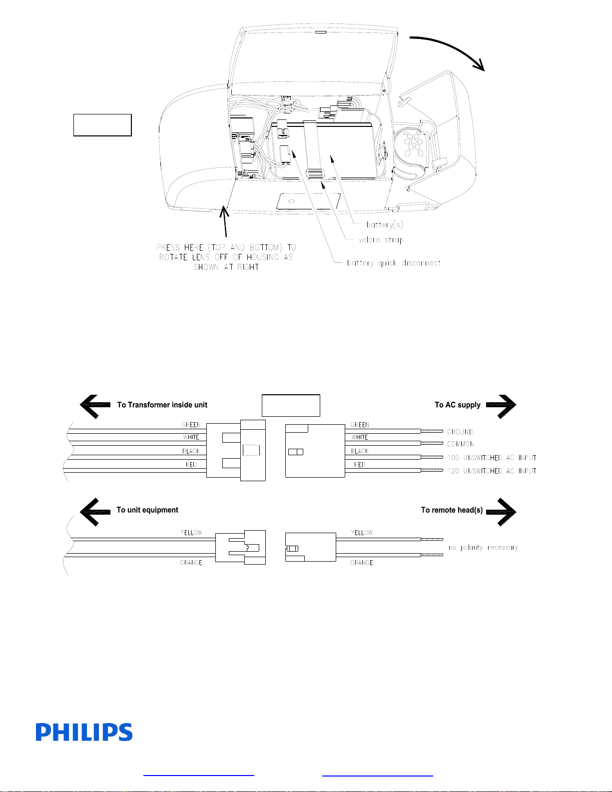
Figure 1
STEP 1 (see figure 1)
Expose junction box mounting pattern by loosening velcro strap over battery or batteries
and removing them from the housing (leave velcro strap in the housing). A quick disconnect is
provided between the electronics and batteries. Be certain that this quick disconnect is
disconnected before attempting to remove batteries. If it is planned to use toggle bolts to mount
unit to wall, additional knockouts intended for this purpose can be found under the lenses. These
keyhole slots will accommodate #6 toggle bolts. Refer to the sketch above for instructions on
removing the lenses.
Figure 2
STEP 2 (see figure 2)
Locate 4 pole connector attached to transformer inside unit. Remove 6” long extension
cable and wire to AC supply as shown. Unused black or blue lead must be insulated to prevent
shorting. If your unit has battery capacity in excess of the wattage required by its internal lamp
heads, it will be provided with a 2 pole remote lamp connector as well. Remote lamp heads used
must match voltage of unit (6 or 12 volt) and the combined wattage of the internal and remote
lamp heads must not exceed the rated wattage of the equipment – refer to nameplate label for
maximum wattage. If unit is not used to power any remote heads, be certain to insulate the unused
orange and yellow leads to prevent shorting or discard the 6” orange/yellow extension cable.
Page 3

Philips Lighting North America Corporation
200 Franklin Square Drive
Somerset, NJ 08873, USA
Phone: 855-486-2216
www.philips.com/luminaires
Philips Lighting Canada Ltd.
281 Hillmount Road,
Markham ON, Canada L6C 2S3
Phone: 800-668-9008
www.philips.com/luminaires
9140053520 February 2016
Figure 3
STEP 3 (see figure 3)
Remove desired knockouts for junction box or toggle bolt mounting. Also remove the
larger rectangular knockout for routing of AC leads unless using the conduit knockout found on
top of the housing. Mount unit to wall or ceiling using fasteners supplied with junction box or
mount to wall using toggle bolts (not provided). Pull AC and remote lamp connectors through
rectangular knockout and reconnect to matching wire harnesses as shown in step two. Reinstall
the battery and connect the battery quick disconnect. Re-secure the Velcro battery strap to secure
the battery in place. If MR-16 type lamps have been specified, they have been shipped in small
individual cartons inside the larger shipping carton. They are installed by press fitting into the
ceramic lamp base inside each lamp head. Energize AC supply branch circuit and refer to page 5
for operating instructions.
No rigid conduit – Flexible conduit only
Page 4

Philips Lighting North America Corporation
200 Franklin Square Drive
Somerset, NJ 08873, USA
Phone: 855-486-2216
www.philips.com/luminaires
Philips Lighting Canada Ltd.
281 Hillmount Road,
Markham ON, Canada L6C 2S3
Phone: 800-668-9008
www.philips.com/luminaires
9140053520 February 2016
MAINTENANCE
LAMP HEAD AIMING – Remove lens covers as shown in step 1. Lamp heads may be aimed by
grasping them at the base and rotating them to aim at the desired location. Lamp head only rotates
approximately 135° which is enough to aim in any direction whether mounted on wall or ceiling.
AC FUSE AND AC OR DC DISCONNECT SWITCH OPTIONS – If ordered, these options can
be found under the right lamp head lens.
TAMPERPROOFING – If ordered, install this option using the included screw kit which includes
two flat head screws, two pan head screws and a tamperproof Torx T-15 bit.
Page 5

Philips Lighting North America Corporation
200 Franklin Square Drive
Somerset, NJ 08873, USA
Phone: 855-486-2216
www.philips.com/luminaires
Philips Lighting Canada Ltd.
281 Hillmount Road,
Markham ON, Canada L6C 2S3
Phone: 800-668-9008
www.philips.com/luminaires
9140053520 February 2016
Self Diagnostic System Operation – Emergency Light or EXIT Sign Products
Normal Power Up Sequence
At power up the red and green LED indicators will alternately flash for one to two seconds. Next the product will execute a
“Power Up Quick Test” causing the green LED indicator to flash rapidly. If any faults are detected during the “Power Up Quick
Test” these will be evident by a flashing red LED indicator. If the audible diagnostic option has been ordered, the flashing red
LED will be accompanied by a simultaneous beeping tone. (Note: A continuous rapid alternating Red/Green flash with rapid
beeping tone indicates incorrect voltage applied to input lead. TURN OFF POWER IMMEDIATELY!)
Emergency Operation
Emergency operation occurs when AC power fails. The product remains in emergency operation until AC power is restored or
battery capacity is depleted. During emergency operation both red and green LED indicators are disabled.
User Interface
Green LED indicator
Slow Flash/Continuous ON = AC power present; normal operating condition
Rapid Flash = product performing an automatic or manually initiated diagnostic test
Red LED indicator
Single Flash = battery fault
Two Flashes = lamp failure (light bar failure – EXIT signs)
Three Flashes = charger fault
Four Flashes = transfer fault
(If more than one fault condition is present simultaneously, the red LED will flash the indication pattern for each fault
independently then repeat the cycle.)
Pushbutton Test Switch
Long Press (longer than 0.5sec) transfers product to emergency operation during time the button is pressed.
Short Press initiates self diagnostic activities as follows:
One Press cancels diagnostic test presently running.
Two Presses starts a one minute diagnostic test.
Three Presses starts a 90 minute diagnostic test.
Four Presses conducts a lamp load calibration (emergency light products only).
Seven Presses initiates a system reset.
(Note: the microprocessor will allow up to seven, one minute diagnostic tests within the first 24 hours of
operation. Allow 24 hours of charging before performing any long duration testing.)
Buzzer (optional)– Sounds in unison with the flashing red LED if a fault condition is present. Buzzer may be silenced for
up to 196 hours by a short press of either the test switch or the optional IR remote control device “silence” button.
Correcting fault condition will cancel fault notification. Lamp failure indication requires a manually activated diagnostic
test after lamp replacement to cancel notification.
IR Remote Control (optional)- is a hand held device that allows remote activation of diagnostic testing and silencing of
the optional buzzer during fault conditions.
Page 6

Philips Lighting North America Corporation
200 Franklin Square Drive
Somerset, NJ 08873, USA
Phone: 855-486-2216
www.philips.com/luminaires
Philips Lighting Canada Ltd.
281 Hillmount Road,
Markham ON, Canada L6C 2S3
Phone: 800-668-9008
www.philips.com/luminaires
9140053520 February 2016
 Loading...