

Page 1
Philips Lighting North America
Corporation
200 Franklin Square Drive
Somerset, NJ 08873, USA
Phone: 855-486-2216
www.philips.com/luminaires
Remote
Connector
(Optional)
NORMAL OPERATION/MANUAL TEST
727854001
February 2016
Lamp
Connector
Lamp
Philips Lighting Canada Ltd.
281 Markham Road,
Markham, ON, Canada L6C
2S3
Phone: 800-668-9008
www.philips.com/luminaires
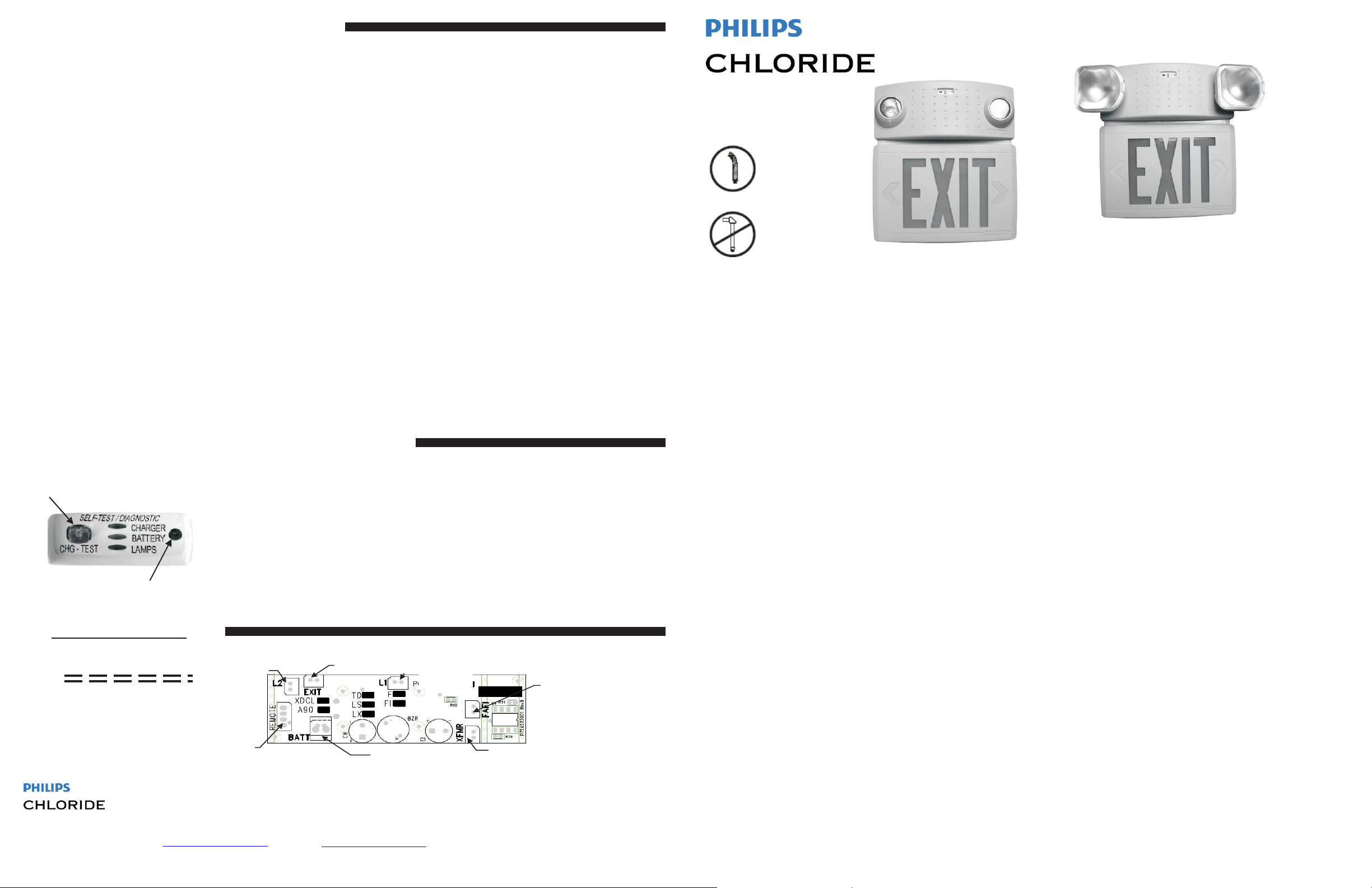
OP-PANEL INDICATORS/OPERATION:
Green Status: Solid indicates system normal and AC power is on.
NOTE: To start the Manual test, simply press the Green Indicator (button) as indicated below. To Reset/Cancel a test press the Green Indicator
(button) once during any test. When Unit is in test mode the Green Indicator LED is flashing.
1 Press: perform a 5 sec brief lamp test, all Lamps operating from battery only.
2 Presses: perform a 1-min diagnostic test, all Lamps operating from battery
only.
3 Presses: perform a 90-min diagnostic test, all Lamps operating from battery
only.
6-Sec Continuous
CONTINUOUS MONITORING: The system monitors the following continuously:
1) Battery, 2) Lamps, 3) Charger, 4) Transfer function.
The battery requires at least 72 hours of charge time to perform any extended diagnostic test. If the battery has not charged for 72 hours after
installation and a diagnostic test is requested, the charger light will come on and stay on for one minute indicating that the battery is not fully charged
for attempted test. (The 5-sec brief lamp test is always allowed.)
Press: perform a RESET operation.
OPTIONAL FACTORY EQUIPPED ITEMS:
REMOTE: Unit will be supplied with pigtail connector cable required to control and operate a remote of up to rated MAX. wattage.
TIME DELAY (TD): After a power failure and power is restored, the lamps will remain lit for a 15-min period (provided battery capacity remains).
Note: The Green power indicator LED will flash slowly during the 15-min. period.
LASER TEST (LX): To operate using a laser pen: use laser pen and point the laser beam over the remote sensor (see below), thereby duplicating the
manual button (1,2,3) pushes. The laser must impact the remote sensor for at least 0.2 seconds to be recognized.
FIRE ALARM INTERFACE (FI): Unit will be supplied with a connector at the FAFI location and an interface cable to connect to the building system (per
wiring diagram).
FLASHING EM (F): Unit will flash the EXIT sign when operation from the battery only. (Flash rate is 1 flash/sec with a 70”-on duty cycle.
BUZZER EM (B): Unit will buzz for approx. ½ -sec during power-up sequence or after a reset operation. Buzzer does not activate during either manual or
automatic testing. Buzzer will only activate when operating from the battery and only due to AC power loss.
LESS SELF-TEST (LS): Monthly automatic self-tests will not be performed. (Lamps will not energize on an automatic monthly schedule.)
TROUBLE INDICATORS/TROUBLESHOOTING
TEST
Button
WIRING INFORMATION
Transformer Inputs
BLACK - 120V
WHITE - Common or
Neutral
RED - 277V
Diagnostic Charger
REMOTE SENSOR
(IF EQUIPPED)
Xtest DISPLAY PANEL INDICAT
GREEN - Status: solid indicates system normal and AC power is on and flashes during any manual/auto test
cycle.
RED CHARGER FLASHING: a charger failure requires the diagnostic charger board to be replaced.
RED BATTERY FLASHING: battery is disconnected or if it is connected, a replacement is needed.
RED LAMP FLASHING: Lamp(s) is disconnected or if it is connected, a replacement is needed. (If
4-pin remote pigtail is connected to diagnostic charger board and no remote lamp is attached, the
LAMPS indicator will flash. Connect a remote lamp or disconnect remote pigtail.)
ALL 3 RED FLASHING: bad transfer; battery and lamps are disconnected or if they are connected a
replacement diagnostic charger board is needed.
OR:
FIRE-ALARM
Board
Equipped)
Factory Cable- Two
White wires; No
polarity required.
(If
Battery Connector
Only
Flexible Conduit
No Rigid Conduit
Emergency Lighting
COMPAC Thermoplastic Combos
IMPORTANT SAFEGUARDS
CCAX/CCTX
INSTRUCTION SHEET
READ AND FOLLOW ALL SAFETY INSTRUCTIONS
WARNING: Electrical Shock Potential!! Do not attempt to install, maintain or relamp without disconnecting all
power. Failure to disconnect power can result in electrocution, shock, or severe burns.
CAUTION: This fixture is designed for permanent installation in ordinary (NON-HAZARDOUS) locations in
accordance with the National Electrical Code and all applicable local codes. Do not use in areas of limited ventilation or
in high ambient enclosures. The lamp and fixture operate at high temperatures; contact with combustible material can
cause fire and personal contact can cause severe burns. When using electrical
equipment, basic safety precautions should always be followed; including the following:
READ AND FOLLOW ALL SAFETY INSTRUCTIONS.
Do not use outdoors.
Do not let power supply cords touch hot surfaces.
Do not mount near gas or electric heaters.
Use caution when servicing batteries. Battery acid can cause burns to skin and eyes. If acid is spilled on
skin or in eyes, flush acid with fresh water and contact a physician immediately.
Equipment should be mounted in locations and at heights where it will not readily be
subjected to tampering by unauthorized personnel.
The use of accessory equipment not recommended by the manufacturer may cause an unsafe condition.
CAUTION: Halogen cycle lamp(s) are used in this equipment. To avoid shattering: Do not operate lamp in
excess of rated voltage, protect lamp against abrasion and scratches and against liquids when lamp is
operating, dispose of lamp with care.
Halogen cycle lamps operate at high temperatures. Do not store or place flammable materials near
lamp.
Do not use this equipment for other than intended use.
Servicing of this equipment should be performed by qualified personnel only.
Series
SAVE THESE
INSTRUCTIONS
Page 2
Philips Lighting North America Corporation
200 Franklin Square Drive
Somerset, NJ 08873, USA
Phone: 855-486-2216
www.philips.com/luminaires
INST
719491102
CMANU0494A
February 2016
Philips Lighting Canada Ltd.
281 Markham Road,
Markham, ON, Canada L6C 2S3
Phone: 800-668-9008
www.philips.com/luminaires
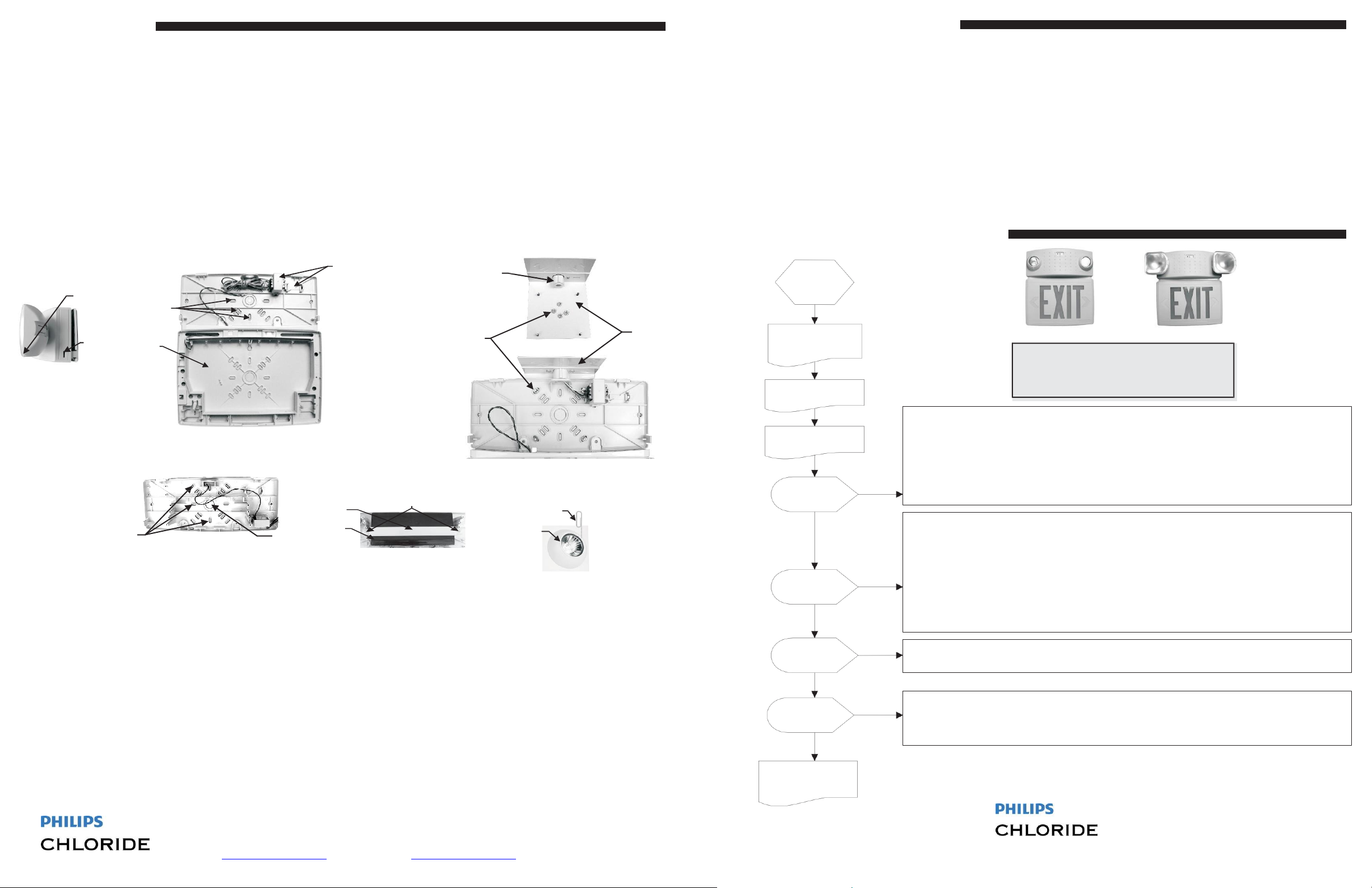
Fig. 3
CCTX
Fig. 5
CCAX
ALLATION
INSTRUCTIONS WALL (BACK) MOUNT
Open front cover using a flat-head screwdriver by pressing the tab on the side of the unit in to release; see Fig. 1.
Remove main knockout hole in back housing and appropriate outlet box pattern knockout; see Fig. 2 or Fig. 3a. If needed, loosen screws holding battery in
place (see Fig. 3b) and remove battery.
Route AC service wires through main knockout hole in back housing. Mount back housing to outlet box using screws. See Fig. 2. Note: If needed, secure
EXIT back housing to wall with appropriate anchors.
Make AC service connection at this time. See OPERATING INSTRUCTIONS below.
Replace the cover and snap tabs into place; see Fig. 1.
INSTRUCTIONS CEILING MOUNT - Requires Ceiling Kit P/N: CCFCK
Open front cover using a flat-head screwdriver by pressing the tab on the side of the unit in to release; see Fig. 1. Assemble flat
plate to L-bracket of ceiling kit using screws.
Remove outer square pattern of knockouts in back housing and assemble ceiling kit to back housing using nuts; see Fig. 4.
Route AC service wires through wire chase in ceiling kit. Mount back housing to ceiling/surface box using mounting plate and screws. See Fig. 4.
Make AC service connection at this time. See OPERATING INSTRUCTIONS below.
Replace the cover and snap tabs into place; see Fig. 1.
Lens
Release
(push in)
Tab
Outlet Box
Knockouts
EXIT
Back Housing
Fig. 1
CCTX
Outlet Box
Knockouts
3a. Knockouts
Fig. 2
CCAX shown
Main
Knockout
Battery Strap
Battery
OPERATING INSTRUCTIONS
1. Connect AC supply wires to transformer leads and push through knockout into outlet or ceiling/surface box. Observe the wire colors.
BLACK wire 120 volt AC input.
WHITE wire common or neutral for 120 or 277 volts AC input. RED
wire 277 volt AC input.
CAUTION: CAP ALL UNUSED BLACK OR RED WIRES TO PREVENT SHORTING OR ELECTRICAL SHOCK.
Note: when all wiring connections are made, push wires thru knockout into outlet box.
2. Make internal wiring connections, reinstall battery at this time if required. See Fig.3b:
a. Connect the red and black wire with the 2-pin connector from battery to BATT connector on the charger board on inside of front cover, if not already connected.
b. Connect the red and white wire with the 2-pin connector from transformer to XFMR connector on the charger board on inside of front cover.
c. Connect the wires with the 2-pin connector and both wires the same color from lamp head to L1 and L2 on the charger board on inside on front cover.
d. Connect the red and black twisted wire with the 2-pin connector from EXIT sign to EXIT connector on the charger board on inside of front cover.
3. Energize AC power to equipment and check the unit using the POWER-UP SEQUENCE (see next page). Leave AC connected for a minimum of 72 hours to charge battery
before performing normal operation/manual tests.
Transformer
Locations
Battery Screws
3b. Battery
Nuts
Wire
Chase
CAX
Retaining
Ring
Fig. 4
Paperclip
CCFCK
INSTALLATION CONTINUED
INSTRUCTIONS LAMP REPLACEMENT -
CCTX -Open lens using a small flat-head screwdriver by gently releasing the tab on the corner of the lamp head; see Fig. 1. Replace lamp, snap cover back into
place.
CCAX-Open front cover (see instructions above), disconnect lamp from the diagnostic charger board. Using an opened paper clip, release the lamp retaining ring;
see Fig. 5. Replace with new lamp. Reinstall retaining ring and connect new lamp to diagnostic charger board. Snap cover back into place.
REMOTE LAMP HEAD HOOKUP INSTRUCTIONS (If remote
NOTE: Observe output rating and do not exceed maximum load
1. The Maximum total watts on L1 or L2 must not exceed replacement lamp wattage listed on Nameplate for all CCAX/CCTX units.
2. The remote lamp connection (REMOTE) may not exceed the output rated maximum minus the output on L1 & L2.
3. Do not short the lamp leads to ground.
Failure to
properly
follow
conditions
stated above may result in damage to the unit and void the unit's
NORMAL POWER-UP SEQUENCE
APPLY
ALL INDICATOR
LEDs FLASH 6
TIMES
EMERGENCY LAMPS
BRIEFLY ON
GREEN STATUS - ON
Battery Charging
INDICATOR
FLASHING
BATTERY
N
LAMP
N
CHARGE
N
N
INDICATOR
FLASHING
INDICATOR
FLASHING
ALL 3 RED
INDICATORS
FLASHING
TO NORMAL
OPERATION
Y
Y
Y
Y
BATTERY DIAGNOSTIC INDICATOR FLASHING AFTER POWER-UP:
1) Most likely the Battery is not connected. Verify that the Battery is connected to the diagnostic charger
board.
2) If the Battery is connected, wait for 72 hours to charge the Battery. After 72 hours, if the Battery
indicator LED is flashing, the Battery is faulty and needs to be replaced.
3) After Battery replacement, the Battery indicator LED will stop flashing within approximately 10 to 20sec.
LAMP DIAGNOSTIC INDICATOR FLASHING AFTER POWER-UP:
1) Verify that the lamps and EXIT sign are connected to the diagnostic charger board. Check the remote
lamp if unit is equipped with remote option.
2) Push the green test switch once to test. All emergency lamps should turn on briefly, if not, replace the
faulty lamp(s).
NOTE: If unit is equipped with remote option, and the remote pigtail (4-pin connector with 2 wires) is
connected to the diagnostic charger board but is not connected to a remote load, the Lamp Indicator
LED will flash. Either connect a load to the remote pigtail or disconnect it from the diagnostic charger
board.
CHARGER DIAGNOSTIC INDICATOR FLASHING AFTER POWER-UP:
1) Indicates a faulty diagnostic charger board that must be replaced.
ALL 3 DIAGNOSTIC INDICATORS FLASHING AFTER POWER-UP:
1) Verify that the lamps and the Battery are connected to the diagnostic charger board.
2) If everything is connected then the Transfer function is faulty and the diagnostic charger board must be
replaced.
Disconnect
combining
SELF-TESTING / SELF-DIAGNOSTIC
The Unit will self-test approximately
every 30 days for a minimum of 30
power before
re-lamping.
capability
all lamp
connections.
warranty
CCAX CCTX
minutes.
is
available)
.
 Loading...