

IMPORTANT SAFETY NOTICE
Proper service and repair is important to the safe, reliable operation of all Philips
Consumer Electronics Company** Equipment. The service procedures recommended by
Philips and described in this service manual are effective methods of performing service
operations. Some of these service operations require the use of tools specially designed
for the purpose. The special tools should be used when and as recommended.
It is important to note that this manual contains various CAUTIONS and NOTICES
which should be carefully read in order to minimize the risk of personal injury to service
personnel. The possibility exists that improper service methods may damage the
equipment. It also is important to understand that these CAUTIONS and NOTICES
ARE NOT EXHAUSTIVE. Philips could not possibly know, evaluate and advise the
service trade of all conceivable ways in which service might be done, or of the possible
hazardous consequences of each way. Consequently, Philips has not undertaken any such
broad evaluation. Accordingly, a servicer who uses a service procedure or tool which is
not recommended by Philips must first satisfy himself thoroughly that neither his safety
nor the safe operation of the equipment will be jeopardized by the service method
selected.
** Hereafter throughout this manual, Philips Consumer Electronics Company will be
referred to as Philips.
WARNING
Critical components having special safety characteristics are identified with a or
"S" by the Ref. No. in the parts list and enclosed within a broken line* (where
several critical components are grouped in one area) along with the safety symbol
on the schematics or exploded views. Use of substitute replacement parts which
do not have the same specified safety characteristics may create shock, fire, or other
hazards. Under no circumstances should the original design be modified or altered
without written permission from Philips. Philips assumes no liability, express or
implied, arising out of any unauthorized modification of design. Servicer assumes all
liability.
* Broken Line ____ _ ____ _ ____ _ ____

FIRE AND SHOCK HAZARD
1. Be sure all components are positioned in such a way as to avoid the possibility of adjacent component
shorts. This is especially important on those chassis which are transported to and from the service shop.
2. Never release a repaired unit unless all protective devices such as insulators, barriers, covers, strain
reliefs, and other hardware have been installed in accordance with the original design.
3. Soldering and wiring must be inspected to locate possible cold solder joints, solder splashes, sharp solder
points, frayed leads, pinched leads, or damaged insulation (including the ac cord). Be certain to remove
loose solder balls and all other loose foreign particles.
4. Check across-the-line components and other components for physical evidence of damage or
deterioration and replace if necessary. Follow original layout, lead length, and dress.
5. No lead or component should touch a receiving tube or a resistor rated at 1 watt or more. Lead tension
around protruding metal surfaces or edges must be avoided.
6. Critical components having special safety characteristics are identified with an 'S' by the Ref. No. in the
parts list and enclosed within a broken line* (where several critical components are grouped in one area)
along with the safety symbol on the schematic diagrams and /or exploded views.
7. When servicing any unit, always use a separate isolation transformer for the chassis. Failure to use a
separate isolation transformer may expose you to possible shock hazard, and may cause damage to
servicing instruments.
8. Many electronic products use a polarized ac line cord (one wide pin on the plug). Defeating this safety
feature may create a potential hazard to the servicer and the user. Extension cords which do not
incorporate the polarizing feature should never be used.
9. After reassembly of the unit, always perform an ac leakage test or resistance test from the line cord to all
exposed metal parts of the cabinet. Also, check all metal control shafts (with knobs removed), antenna
terminals, handles, screws, etc., to be sure the unit may be safely operated without danger of electrical
shock.
* Broken line ____ _ ____ _ ____ _ ____

LEAKAGE CURRENT COLD CHECK
1. Unplug the ac line cord and connect a jumper between the two prongs of the plug.
2. Turn on the power switch.
3. Measure the resistance value between the jumpered ac plug and all exposed cabinet parts of the receiver,
such as screw heads, antennas, and control shafts. When the exposed metallic part has a return path to the
chassis, the reading should be between 1 megohm and 5.2 megohms. When the exposed metal does not
have a return path to the chassis, the reading must be infinity. Remove the jumper from the ac line cord.
LEAKAGE CURRENT HOT CHECK
1. Do not use an isolation transformer for this test. Plug the completely reassembled receiver directly into
the ac outlet.
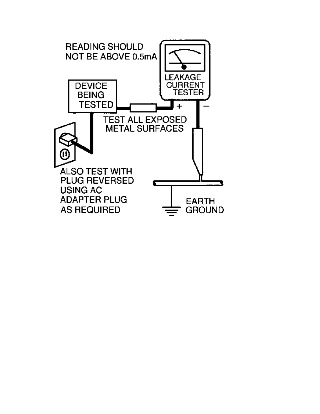
2. Connect a 1.5k, 10W resistor paralleled by a 0.15uF. capacitor between each exposed metallic cabinet
part and a good earth ground such as a water pipe, as shown below.
3. Use an ac voltmeter with at least 5000 ohms/volt sensitivity to measure the potential across the resistor.
4. The potential at any point should not exceed 0.75 volts. A leakage current tester may be used to make
this test; leakage current must not exceed 0.5mA. If a measurement is outside of the specified limits,
there is a possibility of shock hazard. The receiver should be repaired and rechecked before returning it
to the customer.
5. Repeat the above procedure with the ac plug reversed. (Note: An ac adapter is necessary when a
polarized plug is used. Do not defeat the polarizing feature of the plug.)
OR
With the instrument completely reassembled, plug the ac line cord directly into a 120Vac outlet. (Do not
use an isolation transformer during this test.) Use a leakage current tester or a metering system that
complies with American National Standards Institute (ANSI) C101.1 Leakage Current for Appliances and
Underwriters Laboratories (UL) 1410, (50.7). With the instrument ac switch first in the on position and
then in the off position, measure from a known earth ground (metal water pipe, conduit, etc.) to all exposed
metal parts of the instrument (antennas, handle brackets, metal cabinet, screw heads, metallic overlays,
control shafts, etc.), especially any exposed metal parts that offer an electrical return path to the chassis.
Any current measured must not exceed 0.5mA. Reverse the instrument power cord plug in the outlet and
repeat the test. See the graphic below.

TV-VCR SAFETY NOTES
SAFETY PRECAUTIONS FOR TV CIRCUITS
1. Before returning an instrument to the customer, always make a safety check of the entire instrument,
including, but not limited to, the following items:
a. Be sure that no built-in protective devices are defective or have been defeated during servicing.
Protective shields are provided on this chassis to protect both the technician and the customer.
Correctly replace all missing protective shields, including any removed for servicing convenience.
When reinstalling the chassis and/or other assembly in the cabinet, be sure to put back in place all
protective devices, including but not limited to, nonmetallic control knobs, insulating fishpapers,
adjustment and compartment covers/shields, and isolation resistor/capacitor networks. Do not operate
this instrument or permit it to be operated without all protective devices correctly installed and
functioning. Servicers who defeat safety features or fail to perform safety checks may be liable for any
resulting damage.
b. Be sure that there are no cabinet openings through which an adult or child might be able to insert their
fingers and contact a hazardous voltage. Such openings include, but are not limited to, (1) spacing
between the picture tube and the cabinet mask, (2) excessively wide cabinet ventilation slots, and (3)
an improperly fitted and/or incorrectly secured cabinet back cover.
c. Do a leakage current check.
ANY MEASUREMENTS NOT WITHIN THE LIMITS SPECIFIED HEREIN INDICATE A
POTENTIAL SHOCK HAZARD THAT MUST BE ELIMINATED BEFORE RETURNING THE
INSTRUMENT TO THE CUSTOMER OR BEFORE CONNECTING THE ANTENNA OR
ACCESSORIES.
d. X-Radiation and High Voltage Limits - Because the picture tube is the primary potential source of
X-radiation in solid-state TV receivers, it is specially constructed to prohibit X-radiation emissions.
For continued X-radiation protection, the replacement picture tube must be the same type as the
original. Also, because the picture tube shields and mounting hardware perform an X-radiation
protection function, they must be correctly in place. High voltage must be measured each time
servicing is performed that involves B+, horizontal deflection or high voltage. Correct operation of the
X-radiation protection circuits also must be reconfirmed each time they are serviced. (X-radiation
protection circuits also may be called "horizontal disable" or "hold down.") Read and apply the high
voltage limits and, if the chassis is so equipped, the X-radiation protection circuit specifications given
on instrument labels and in the Product Safety and X-Radiation Warning note on the service data
chassis schematic. High voltage is maintained within specified limits by close tolerance safety-related
components/adjustments in the high-voltage circuit. If high voltage exceeds specified limits, check
each component specified on the chassis schematic and take corrective action.
2. Read and comply with all caution and safety-related notes on or inside the receiver cabinet, on the
receiver chassis, or on the picture tube.
3. Design Alteration Warning - Do not alter or add to the mechanical or electrical design of this TV
receiver. Design alterations and additions, including, but not limited to circuit modifications and the
addition of items such as auxiliary audio and/or video output connections, might alter the safety
characteristics of this receiver and create a hazard to the user. Any design alterations or additions will
void the manufacturer's warranty and may make you, the servicer, responsible for personal injury or
property damage resulting therefrom.

4. Picture Tube Implosion Protection Warning - The picture tube in this receiver employs integral
implosion protection. For continued implosion protection, replace the picture tube only with one of the
same type number. Do not remove, install, or otherwise handle the picture tube in any manner without
first putting on shatterproof goggles equipped with side shields. People not so equipped must be kept
safely away while picture tubes are handled. Keep the picture tube away from your body. Do not handle
the picture tube by its neck. Some "in-line" picture tubes are equipped with a permanently attached
deflection yoke; because of potential hazard, do not try to remove such "permanently attached" yokes
from the picture tube.
5. Hot Chassis Warning
a. Some TV receiver chassis are electrically connected directly to one conductor of the ac power cord and
may be serviced safely without an isolation transformer only if the ac power plug is inserted so that the
chassis is connected to the ground side of the ac power source. To confirm that the ac power plug is
inserted correctly, with an ac voltmeter, measure between the chassis and a known earth ground. If a
voltage reading in excess of 1.OV is obtained, remove and reinsert the ac power plug in the opposite
polarity and again measure the voltage potential between the chassis and a known earth ground.
b. Some TV receiver chassis normally have 85Vac (RMS) between chassis and earth ground regardless of
the ac plug polarity. This chassis can be safety-serviced only with an isolation transformer inserted in
the power line between the receiver and the ac power source, for both personnel and test equipment
protection. Some TV receiver chassis have a secondary ground system in addition to the main chassis
ground. This secondary ground system is not isolated from the ac power line. The two ground systems
are electrically separated by insulation material that must not be defeated or altered.
6. Observe original lead dress. Take extra care to assure correct lead dress in the following areas: a. near
sharp edges, b. near thermally hot parts - be sure that leads and components do not touch thermally hot
parts, c. the ac supply, d. high voltage, and e. antenna wiring. Always inspect in all areas for pinched,
out of place, or frayed wiring. Check ac power cord for damage.
7. Components, parts, and/or wiring that appear to have overheated or are otherwise damaged should be
replaced with components, parts, or wiring that meet original specifications. Additionally, determine the
cause of overheating and/or damage and, if necessary, take corrective action to remove any potential
safety hazard.

PRECAUTIONS DURING SERVICE
A. Parts identified by the symbol are critical for safety. Replace only with part number specified.
B. In addition to safety, other parts and assemblies are specified for conformance with regulations
applying to spurious radiation. These must also be replaced only with specified replacements.
Examples: RF converters, RF cables, noise blocking capacitors, and noise blocking filters, etc.
C. Use specified internal wiring. Note especially:
1) Wires covered with PVC tubing
2) Double insulated wires
3) High voltage leads
D. Use specified insulating materials for hazardous live parts. Note especially:
1) Insulation Tape
2) PVC tubing
3) Spacers
4) Insulators for transistors
E. When replacing ac primary side components (transformers, power cord, etc.), wrap ends of wires
securely about the terminals before soldering.
F. Observe that the wires do not contact heat producing parts (heat sinks, oxide metal film resistors,
fusible resistors, etc.)
G. Check that replaced wires do not contact sharp edged or pointed parts.
H. When a power cord has been replaced, check that 10-15 kg of force in any direction will not loosen it.
I. Also check areas surrounding repaired locations.
J. Use care that foreign objects (screws, solder droplets, etc.) do not remain inside the set.
K. Crimp type wire connector
When replacing the power transformer in sets where the connections between the power cord and
power transformer primary lead wires are performed using crimp type connectors, in order to prevent
shock hazards, perform carefully and precisely the following steps.
Replacement procedure
1) Remove the old connector by cutting the wires at a point close to the connector. Important: Do not
re-use a connector (discard it).
2) Strip about 15 mm of the insulation from the ends of the wires. If the wires are stranded, twist the
strands to avoid frayed conductors.
3) Align the lengths of the wires to be connected. Insert the wires fully into the connector.
4) Use the crimping tool to crimp the metal sleeve at the center position. Be sure to crimp fully to the
complete closure of the tool.
L. When connecting or disconnecting the VCR connectors, first disconnect the ac plug from the ac supply
socket.
SAFETY CHECK AFTER SERVICING
Examine the area surrounding the repaired location for damage or deterioration. Observe that screws, parts
and wires have been returned to original positions. Afterwards, perform the following test and confirm the
specified values in order to verify compliance with safety standards.
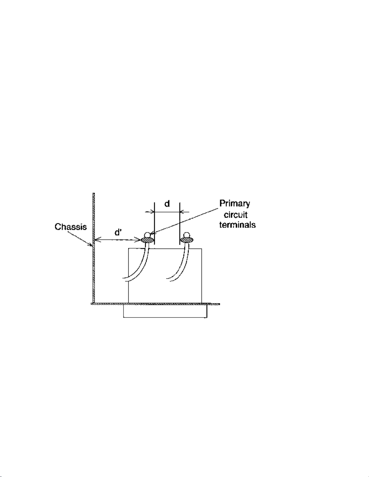
Clearance Distance
When replacing primary circuit components, confirm specified clearance distance (d) and (d') between
soldered terminals, and between terminals and surrounding metallic parts. See the graphic below.
Table 1: Ratings for selected area
AC Line Voltage Region Clearance Distance
(d) (d')
USA or > 3.2 mm
110 to 130 V CANADA (0.126 inches)
Note: This table is unofficial and for reference only. Be sure to confirm the precise values.

SAFETY CHECKS
After the original service problem has been corrected, a complete safety check should be made. Be sure to
check over the entire set, not just the areas where you have worked. Some previous servicer may have left
an unsafe condition, which could be unknowingly passed on to your customer. Be sure to check all of the
following:
Fire and Shock Hazard
Implosion
X-Radiation
Leakage Current Cold Check
Leakage Current Hot Check
Picture Tube Replacement
Parts Replacement
WARNING: Before removing the CRT anode cap, turn the unit OFF and short the HIGH VOLTAGE to
the CRT DAG ground.
SERVICE NOTE: The CRT DAG is not at chassis ground.
IMPLOSION
1. All picture tubes used in current model receivers are equipped with an integral implosion system.
Care should always be used, and safety glasses worn, whenever handling any picture tube. Avoid
scratching or otherwise damaging the picture tube during installation.
2. Use only replacement tubes specified by the manufacturer.
X-RADIATION
1. Be sure procedures and instructions to all your service personnel cover the subject of X-radiation.
Potential sources of X-rays in TV receivers are the picture tube and the high voltage circuits. The
basic precaution which must be exercised is to keep the high voltage at the factory recommended
level.
2. To avoid possible exposure to X-radiation and electrical shock, only the manufacturer's specified
anode connectors must be used.
3. It is essential that the service technician has an accurate HV meter available at all times. The
calibration of this meter should be checked periodically against a reference standard.
4. When the HV circuitry is operating properly there is no possibility of an X-radiation problem. High
voltage should always be kept at the manufacturer's rated value - no higher - for optimum
performance. Every time a color set is serviced, the brightness should be run up and down while
monitoring the HV with a meter to be certain that the HV is regulated correctly and does not exceed
the specified value. We suggest that you and your technicians review test procedures so that HV and
HV regulation are always checked as a standard servicing procedure, and the reason for this prudent
routine is clearly understood by everyone. It is important to use an accurate and reliable HV meter. It
is recommended that the HV reading be recorded on each customer's invoice, which will
demonstrate a proper concern for the customer's safety.
5. When troubleshooting and making test measurements in a receiver with a problem of excessive high
voltage, reduce the line voltage by means of a Variac to bring the HV into acceptable limits while
troubleshooting. Do not operate the chassis longer than necessary to locate the cause of the excessive HV.

6. New picture tubes are specifically designed to withstand higher operating voltages without creating
undesirable X-radiation. It is strongly recommended that any shop test fixture which is to be used
with the new higher voltage chassis be equipped with one of the new type tubes designed for this
service. Addition of a permanently connected HV meter to the shop test fixture is advisable. The
CRT types used in these new sets should never be replaced with any other types, as this may result in
excessive X-radiation.
7. It is essential to use the specified picture tube to avoid a possible X-radiation problem.
8. Most TV receivers contain some type of emergency "Hold Down" circuit to prevent HV from rising
to excessive levels in the presence of a failure mode. These various circuits should be understood by
all technicians servicing them, especially since many hold down circuits are inoperative as long as
the receiver performs normally.
PICTURE TUBE REPLACEMENT
The primary source of X-radiation in this television receiver is the picture tube. The picture tube
utilized in this chassis is specially constructed to limit X-radiation emissions. For continued Xradiation protection, the replacement tube must be the same type as the original, including suffix letter,
or a Philips approved type.
PARTS REPLACEMENT
Many electrical and mechanical parts in Philips television sets have special safety related
characteristics. These characteristics are often not evident from visual inspection nor can the protection
afforded by them necessarily be obtained by using replacement components rated for higher voltage,
wattage, etc. The use of a substitute part which does not have the same safety characteristics as the
Philips recommended replacement part shown in this service manual may create shock, fire, or other
hazards.
PRODUCT SAFETY GUIDELINES FOR ALL PRODUCTS
CAUTION: Do not modify any circuit. Service work should be performed only after you are thoroughly
familiar with all of the following safety checks. Risk of potential hazards and injury to the user increases if
safety checks are not adhered to.
USE A SEPARATE ISOLATION TRANSFORMER FOR THIS UNIT WHEN SERVICING.

PREVENTION OF ELECTROSTATIC DISCHARGE (ESD)
Some semiconductor solid state devices can be damaged easily by static electricity. Such components
commonly are called Electrostatically Sensitive (ES) Devices, Examples of typical ES devices are
integrated circuits and some field-effect transistors and semiconductor "chip" components. The following
techniques should be used to help reduce the incidence of component damage caused by electrostatic
discharge (ESD).
1. Immediately before handling any semiconductor component or semiconductor-equipped assembly, drain
off any ESD on your body by touching a known earth ground. Alternatively, obtain and wear a
commercially available discharging ESD wrist strap, which should be removed for potential shock
reasons prior to applying power to the unit under test.
2. After removing an electrical assembly equipped with ES devices, place the assembly on a conductive
surface such as aluminum foil, to prevent electrostatic charge buildup or exposure of the assembly.
3. Use only a grounded-tip soldering iron to solder or unsolder ES devices.
4. Use only an anti-static solder removal device. Some solder removal devices not classified as "antistatic
(ESD protected)" can generate an electrical charge sufficient to damage ES devices.
5. Do not use Freon propelled chemicals. These can generate electrical charges sufficient to damage ES
devices.
6. Do not remove a replacement ES device from its protective package until immediately before you are
ready to install it (most replacement ES devices are packaged with leads electrically shorted together by
conductive foam, aluminum foil or comparable conductive material).
7. Immediately before removing the protective material from the leads of a replacement ES device, touch
the protective material to the chassis or circuit assembly into which the device will be installed.
CAUTION: Be sure no power is applied to the chassis or circuit and observe all other safety precautions.
8. Minimize bodily motions when handling unpackaged replacement ES devices. (Otherwise harmless
motion such as the brushing together of your clothes fabric or the lifting of your feet from a carpeted
floor can generate static electricity (ESD) sufficient to damage an ES device.)
NOTE to CATV system Installer:
This reminder is provided to call the CATV system installer's attention to article 820-22 of the NEC that
provides guidelines for proper grounding and, in particular, specifies that the cable ground shall be
connected to the grounding system of the building, as close to the point of cable entry as practical.

PRACTICAL SERVICE PRECAUTIONS
IT MAKES SENSE TO AVOID EXPOSURE TO ELECTRICAL SHOCK. While some sources are
expected to have a possible dangerous impact, others of quite high potential are of limited current and are
sometimes held in less regard.
ALWAYS RESPECT VOLTAGES. While some may not be dangerous in themselves, they can cause
unexpected reactions – reactions that are best avoided. Before reaching into the powered color TV set, it is
best to test the high voltage insulation. It is easy to do, and is just a good service precaution.
BEFORE POWERING UP THE TV WITH THE BACK OFF (or on a test fixture), attach a clip lead to
the CRT DAG ground and to a screwdriver blade that has a well insulated handle. After the TV is powered
on and high voltage has developed, probe the anode lead with the blade, starting at the bottom of the High
Voltage Transformer (flyback – IFT). Move the blade to within two inches of the connector of the CRT. IF
THERE IS AN ARC, YOU FOUND IT THE EASY WAY, WITHOUT GETTING A SHOCK! If
there is an arc to the screwdriver blade, replace the High Voltage Transformer or the lead, (if removable)
whichever is causing the problem.
PICTURE TUBE REPLACEMENT PROCEDURE
Note: a. Two (2) people are required to handle this picture tube.
b. Safety Glasses must be worn during this procedure or whenever directly handling a picture tube.
c. Take care in each step not to damage the CRT or the cabinet.
1. Remove the Chassis and the CRT Socket Board Module from the cabinet.
2. A furniture pad or blanket should be positioned on the floor to support only the CRT Face. This pad or
blanket should be high enough to keep the CRT Face approximately 12 to 14 inches off the floor.
3. Using two people, place the cabinet in a front down position with the CRT Face on the pad or blanket.
4. Place padded blocks under each corner of the cabinet to keep it from rocking.
5. Remove the four screws, at the corners of the CRT.
6. With two people lowering the cabinet to the floor, leave the CRT elevated by the pad or blanket.
Note: Take care not to grasp the neck of the CRT during this procedure, as it is extremely fragile.
7. Two (2) people may then lift the CRT from the cabinet.
8. Remove the degaussing coil from the defective CRT and mount on the replacement. Take care to
maintain the exact shape and fit.
To install the new CRT, reverse steps 1 to 7.
SPECIFICATIONS (MODEL CCC090, CCC092)
V Mode: SP mode unless otherwise specified
V Test input terminal
Except Tuner> Video input (1Vp-p)
Audio input (-10dB)
Tuner Ant. input (80dBmV) Video: 87.5%
Audio: 25kHz dev (1kHz Sin)
<DEFLECTION>
Description Condition Nominal Limit
Over Scan — 90% 5
Linearity Horizontal — 12%
Vertical — 10%
High Voltage — 18 kV —
<VIDEO & CHROMA>
Description Condition Nominal Limit
Misconvergence Center — 0.3 m/m
Corner — 1.5 m/m
Side — 1.2 m/m
Tint Control Range — ±30 deg —
Contrast Control Range — 6 dB —
Brightness APL 100% 30 ft-L —
Color Temperature — 9200K —
<VCR>
Description Condition Nominal Limit
Horizontal Resolution (R/P) 230 lines 200 lines
Jitter (Low) (R/P) 0.05 mS 0.2 mS
S/N Chroma AM(SP)
PM (SP)
(R/P) 36 dB 33 dB
Wow & Flutter (RMS) (R/P) 0.25% 0.5%
<TUNER>
Description Nominal Limit
Video S/N 45 dB 40 dB
Audio S/N (W/LPF) 43 dB 40 dB
<AUDIO>
All items are measured across 8W resistor at speaker output terminal.
Description Condition Nominal Limit
Audio Output Power (Max.) (R/P) 0.8 W 0.6 W
Audio S/N (W/LPF) (R/P) 40 dB 36 dB
Audio Distortion (W/LPF) (R/P) 3.0% 5.0%
Audio Freq. Response
(-10dB Ref. 1kHz)
Note: Nominal specifications represent the design specifications. All units should be able to approximate these. Some will
exceed and some may drop slightly below these specifications. Limit specifications represent the absolute worst
condition that still might be considered acceptable. In no case should a unit fail to meet limit specifications.
(R/P) 38 dB 33 dB
200Hz (R/P)
8kHz (R/P)
-2.0 dB
0 dB
-2.0 ± 5.0 dB
0 ± 6.0 dB

SPECIFICATIONS (MODELS CCC130 & 132)
V Mode: SP mode unless otherwise specified
V Test input terminal
Except Tuner> Video input (1Vp-p)
Audio input (-10dB)
Tuner Ant. input (80dBmV) Video: 87.5%
Audio: 25kHz dev (1kHz Sin)
<DEFLECTION>
Description Condition Nominal Limit
Over Scan — 90% 5
Linearity Horizontal — 15%
Vertical — 10%
High Voltage — 22 kV —
<VIDEO & CHROMA>
Description Condition Nominal Limit
Misconvergence Center — 0.3 m/m
Corner — 1.5 m/m
Side — 1.2 m/m
Tint Control Range — ±30 deg —
Contrast Control Range — 6 dB 4 dB
Brightness APL 100% 55 ft-L 40 ft-L
Color Temperature — 9200K —
<VCR>
Description Condition Nominal Limit
Horizontal Resolution (R/P) 230 lines 200 lines
Jitter (Low) (R/P) 0.05 mS 0.2 mS
S/N Chroma AM(SP)
PM (SP)
(R/P) 36 dB 33 dB
Wow & Flutter (RMS) (R/P) 0.25% 0.5%
<TUNER>
Description Nominal Limit
Video S/N 45 dB 40 dB
Audio S/N (W/LPF) 43 dB 40 dB
<AUDIO>
All items are measured across 8W resistor at speaker output terminal.
Description Condition Nominal Limit
Audio Output Power (Max.) (R/P) 1.0 W 0.8 W
Audio S/N (W/LPF) (R/P) 40 dB 36 dB
Audio Distortion (W/LPF) (R/P) 3.0% 5.0%
Audio Freq. Response
(-10dB Ref. 1kHz)
Note: Nominal specifications represent the design specifications. All units should be able to approximate these. Some will
exceed and some may drop slightly below these specifications. Limit specifications represent the absolute worst condition
that still might be considered acceptable. In no case should a unit fail to meet limit specifications.
(R/P) 38 dB 33 dB
200Hz (R/P)
8kHz (R/P)
-2.0 dB
0 dB
-2.0 ± 5.0 dB
0 ± 6.0 dB

SPECIFICATIONS (MODEL CCC190, CC19C1)
V Mode: SP mode unless otherwise specified
V Test input terminal
Except Tuner> Video input (1Vp-p)
Audio input (-10dB)
Tuner Ant. input (80dBmV) Video: 87.5%
Audio: 25kHz dev (1kHz Sin)
<DEFLECTION>
Description Condition Nominal Limit
Over Scan — 90% 5
Linearity Horizontal — 15%
Vertical — 10%
High Voltage — 25 kV —
<VIDEO & CHROMA>
Description Condition Nominal Limit
Misconvergence Center — 0.3 m/m
Corner — 1.5 m/m
Side — 1.2 m/m
Tint Control Range — ±30 deg —
Contrast Control Range — 6 dB —
Brightness APL 100% 35 ft-L —
Color Temperature — 9200K —
<VCR>
Description Condition Nominal Limit
Horizontal Resolution (R/P) 230 lines 200 lines
Jitter (Low) (R/P) 0.05 mS 0.2 mS
S/N Chroma AM(SP)
PM (SP)
(R/P) 36 dB 33 dB
Wow & Flutter (RMS) (R/P) 0.25% 0.5%
<TUNER>
Description Nominal Limit
Video S/N 45 dB 40 dB
Audio S/N (W/LPF) 43 dB 40 dB
<AUDIO>
All items are measured across 8W resistor at speaker output terminal.
Description Condition Nominal Limit
Audio Output Power (Max.) (R/P) 1.0 W 0.8 W
Audio S/N (W/LPF) (R/P) 40 dB 36 dB
Audio Distortion (W/LPF) (R/P) 3.0% 5.0%
Audio Freq. Response
(-10dB Ref. 1kHz)
Note: Nominal specifications represent the design specifications. All units should be able to approximate these. Some will
exceed and some may drop slightly below these specifications. Limit specifications represent the absolute worst condition
that still might be considered acceptable. In no case should a unit fail to meet limit specifications.
(R/P) 38 dB 33 dB
200Hz (R/P)
8kHz (R/P)
-2.0 dB
0 dB
-2.0 ± 5.0 dB
0 ± 6.0 dB

SPECIFICATIONS (Model CCC133, CCC134)
<DEFLECTION>
Description Condition Nominal Limit
Over Scan — 90% —
Linearity Horizontal — 15%
Vertical — 10%
High Voltage — 22 kV —
<VIDEO & CHROMA>
Description Condition Nominal Limit
Misconvergence Center — 0.3 m/m
Corner — 1.5 m/m
Side — 1.2 m/m
Tint Control Range — 30 deg —
Contrast Control Range — 6 dB 4 dB
Brightness APL 100% 55 ft-L 40 ft-L
Color Temperature — 9200 K —
<VCR>
Description Condition Nominal Limit
Horizontal Resolution (R/P) 230 Line 200 Line
Jitter (Low) (R/P) 0.05 mS 0.2 mS
S/N Chroma AM (SP)
PM (SP)
(R/P) 36 dB 33 dB
Wow & Flutter (RMS) (R/P) 0.25% 0.5%
<TUNER>
Description Condition Nominal Limit
Video S/N — 45 dB 40 dB
Audio S/N (W/LPF) — 43 dB 40 dB
<AUDIO>
All items are measured across 8W resistor at speaker output terminal.
Description Condition Nominal Limit
Audio Output Power
(Max.)
Audio S/N (W/LPF) (R/P) 40 dB 36 dB
Audio Distortion (W/LPF) (R/P) 3.0% 5.0%
Audio Freq. Response
(-10dB Ref. 1kHz)
Note: Nominal specifications represent the design specifications. All units should be able to approximate these. Some will
exceed and some may drop slightly below these specifications. Limit specifications represent the absolute worst condition
that still might be considered acceptable. In no case should a unit fail to meet limit specifications.
(R/P) 38 dB 33 dB
(R/P) 1.0 W 0.8 W
200Hz (R/P)
8kHz (R/P)
-2.0 dB
0 dB
-2.0 dB ± 5.0 dB
0 dB ± 6.0 dB

Service Fixtures and Tools
4835 310 57025
VFMS0001H6
Alignment Tape
4835 310 57043
Back Tension Meter
(Made in USA)
Flat Screwdriver
(Purchase Locally)
4835 310 57027
Post Adjustment Screwdriver
Metric Thickness Gauges
(Purchase Locally)
Lock Screwdriver
(Purchase Locally)
4835 310 57034
Head Cleaning Stick
STANDARD NOTES FOR SERVICING
Circuit Board Indications
1. The output pin of the 3 pin Regulator ICs is indicated as shown:
2. For other ICs, pin 1 and every 5th pin are indicated as shown:
3. The 1st pin of every pin connector is indicated as shown:

Instructions for Connectors
1. When you connect or disconnect FFC cable (connector), be sure to disconnect the AC cord.
2. FFC cable (connector) should be inserted parallel into the connector, not at an angle.
Caution:
Once chip parts (Resistors, Capacitors, Transistors, etc.) are removed, they must not be reused. Always use a
new part.
Replacement Procedures for Leadless (Chip) Components
The following procedures are recommended for the replacement of the leadless components used in
this unit.
1. Preparation for replacement
a. Soldering Iron: Use a pencil-type soldering iron (less than 30 watts).
b. Solder: Eutectic solder (Tin 63%, Lead 37%) is recommended.
c. Soldering time: Do not apply heat for more than 4 seconds.
d. Preheating: Leadless capacitor must be preheated before installation. (130°C~150°C, for about two minutes.)
Notes:
a. Leadless components must not be reused after removal.
b. Excessive mechanical stress and rubbing for the component electrode must be avoided.
2. Removing the leadless component
Grasp the leadless component body with tweezers and alternately apply heat to both
electrodes. When the solder on both electrodes has melted, remove leadless
component with a twisting motion.
Notes:
a. Do not attempt to lift the component off the board until the component is completely disconnected from the
board by the twisting action.
b. Take care not to break the copper foil on the printed board.
3. Installing the leadless component
a. Presolder the contact points of the circuit board.
b. Press the part downward with tweezers and solder both electrodes..
Note:
Do not glue the replacement leadless component to the circuit board.
How to Remove / Install Flat Pack IC
Caution:
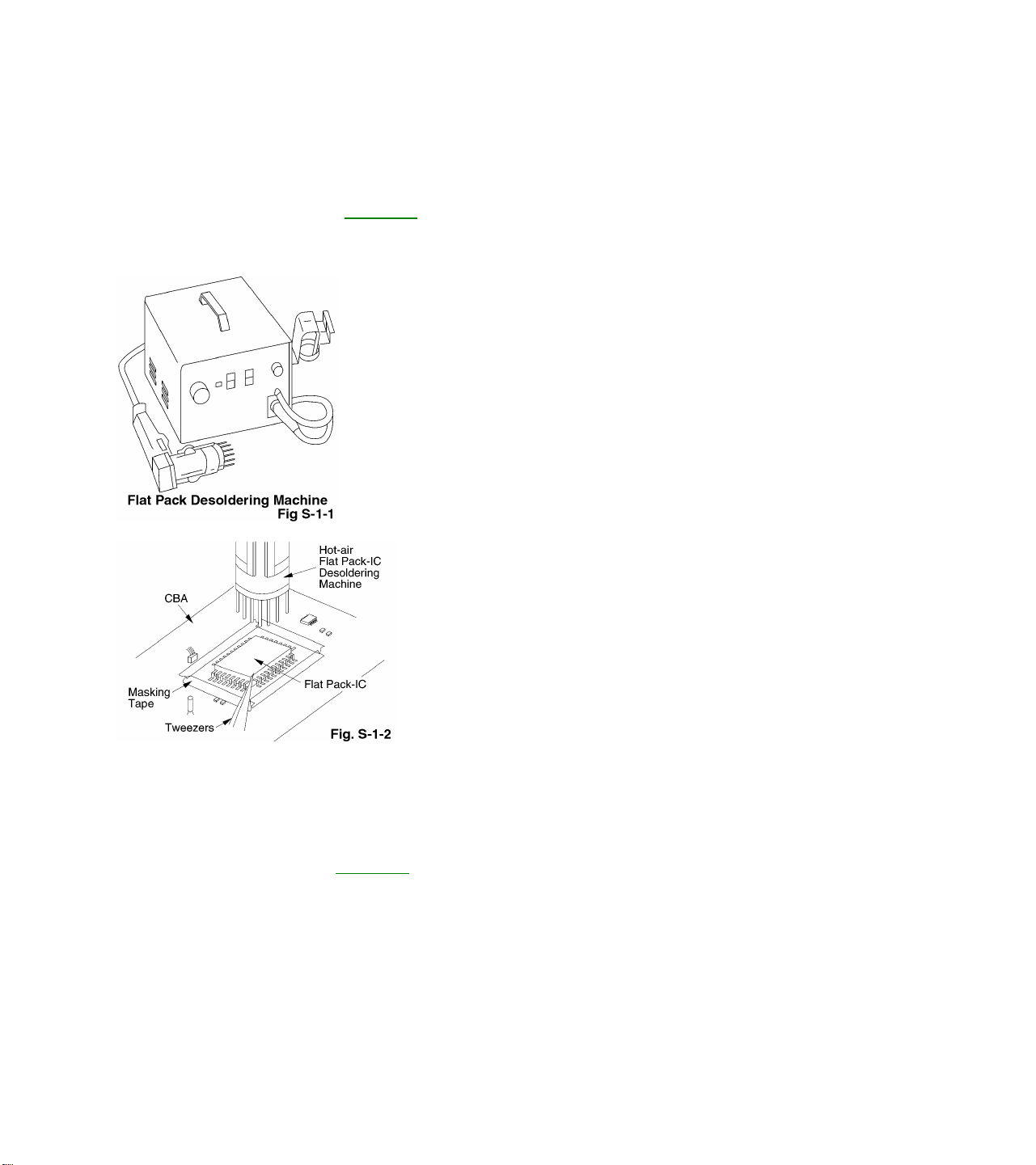
1. Do not apply the hot air to the chip parts around the Flat Pack-IC for over 6 seconds as
damage may occur to the chip parts. Put Masking Tape around the Flat Pack-IC to protect
other parts from damage. (Fig. S-1-2)
2. The Flat Pack-IC on the CBA is affixed with glue, so be careful not to break or damage the
foil of each pin or solder lands under the IC when removing it.
1. Removal
With Hot - Air Flat Pack - IC Desoldering Machine:
a. Prepare the Hot - Air Flat Pack - IC Desoldering Machine, then apply hot air to Flat Pack -
IC (about 5~6 seconds). (Fig. S-1-1)
b. Remove the Flat Pack- IC with tweezers while applying the hot air.
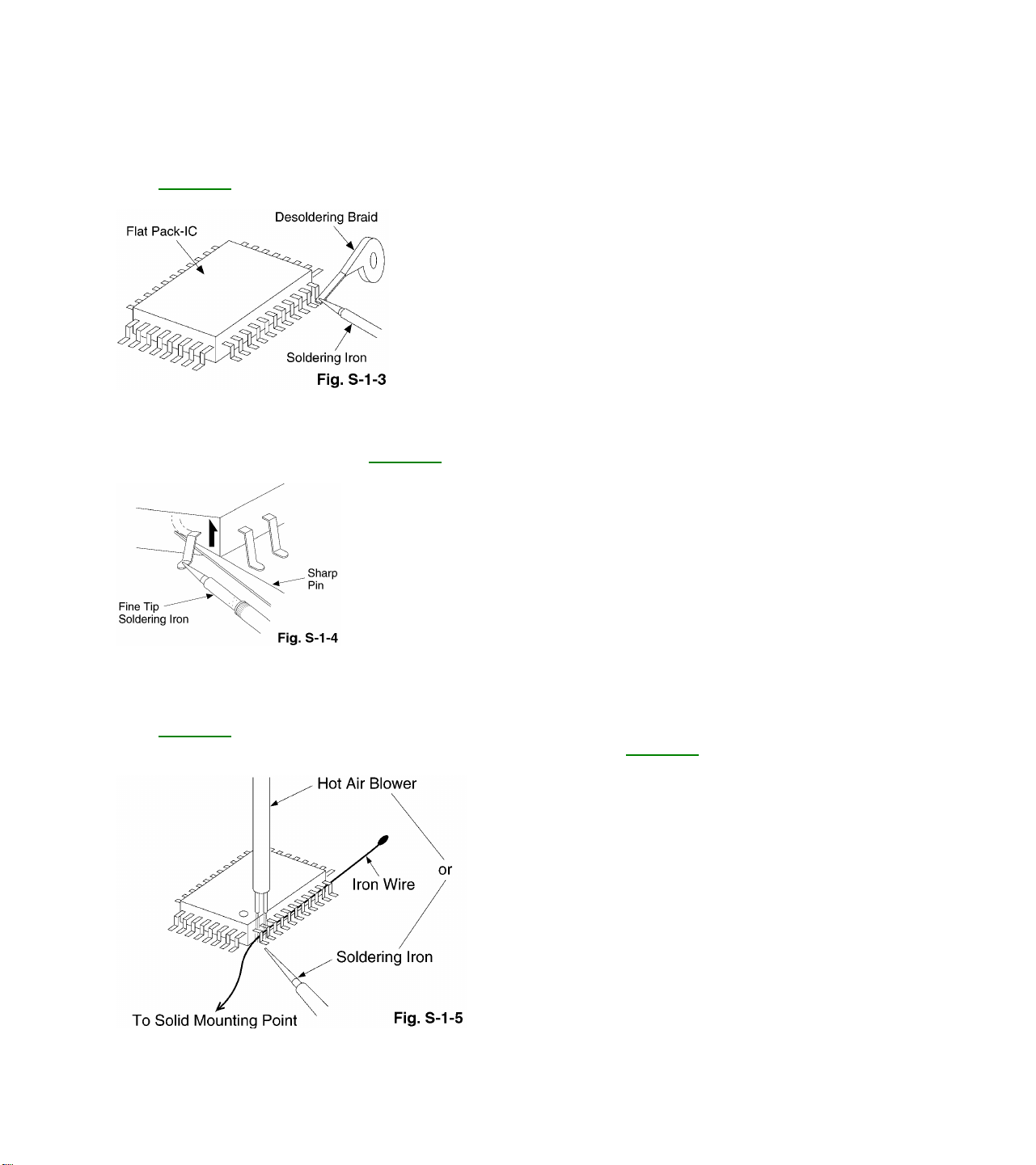
With Soldering Iron:
a. Using desoldering braid, remove the solder from all pins of the Flat Pack - IC. When you
use solder flux which is applied to all pins of the Flat Pack - IC, you can remove it easily.
(Fig. S-1-3)
b. Lift each lead of the Flat Pack - IC upward one by one, using a sharp pin or wire to which
solder will not adhere (iron wire). When heating the pins, use a fine tip soldering iron or a
hot air Desoldering Machine. (Fig. S-1-4)
With Iron Wire:
a. Using desoldering braid, remove the solder from all pins of the Flat Pack - IC. When you
use solder flux which is applied to all pins of the Flat Pack - IC, you can remove it easily.
(Fig. S-1-3)
b. Affix the wire to a workbench or solid mounting point, as shown in Fig. S-1-5.
c. Pull up on the wire as the solder melts so as to lift the IC leads from the CBA contact
pads, while heating the pins using a fine tip soldering iron or hot air blower.
Note:
When using a soldering iron, care must be taken to ensure that the Flat Pack - IC is not
being held by glue, or when it is removed from the CBA, it may be damaged if force is
used.
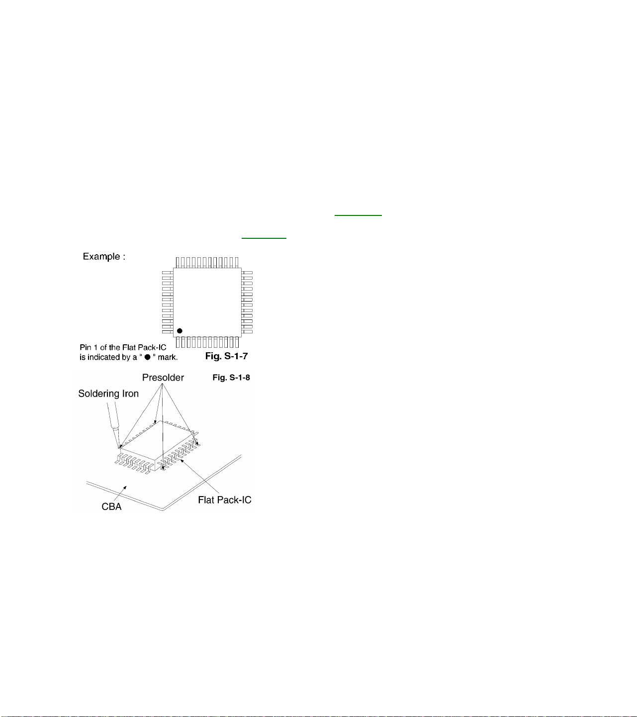
2. Installation
a. Using desoldering braid, remove the solder from the foil of each pin of the Flat Pack - IC
on the CBA, so you can install a replacement Flat Pack - IC more easily.
b. The ”•“ mark on the Flat Pack - IC indicates pin 1 (See Fig. S-1-7). Make sure this mark
matches the 1 on the CBA when positioning for installation. Then pre - solder the four
corners of the Flat Pack- IC (See Fig. S-1-8).
c. Solder all pins of the Flat Pack - IC. Make sure that none of the pins have solder bridges.
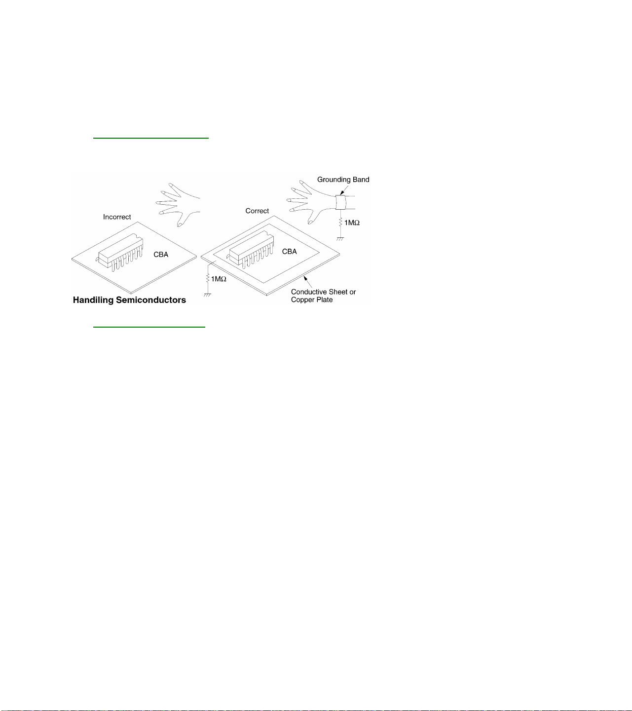
Instructions for Handling Semiconductors
Electrostatic breakdown of the semiconductors may occur due to a potential difference caused
by electrostatic charge during unpacking or repair work.
Ground for Human Body
Be sure to wear a grounding band (1MW) that is properly grounded to remove any static
electricity that may be charged on the body.
Ground for Work Bench
Be sure to place a conductive sheet or copper plate with proper grounding (1MW) on the
work bench or other surface, where the semiconductors are to be placed. Because the
static electricity charge on the clothing will not escape through the body grounding band,
be careful to avoid contacting semiconductors to clothing.
Standard Maintenance
Service Schedule of Components
Deck
Periodic Service Schedule
Ref. No. Part Name 1,000 H 2,000 H 3,000 H 4,000 H
B2 Cylinder Assembly
B3 Loading Motor Assembly
B8 Pulley Assembly
B27 Tension Lever Sub Assembly
B31 AC Head Assembly
B573, B574 Reel (S), Reel (T)
B37 Capstan Motor
B52 Cap Belt
B73 FE Head
B133 Idler Assembly
B410 Pinch Arm (A) Assembly
B414 M Brake S Assembly
B416 M Brake T Assembly
B525 LDG Belt
Notes:
1. Clean all parts for the tape transport (Upper Drum with Video Head/Pinch Roller/Audio Control Head/Full
Erase Head) using 90% Isopropyl Alcohol.
2. After cleaning the parts, do all DECK ADJUSTMENTS.
3. For the reference numbers listed above, refer to Deck Exploded Views.
H: Hours ?: Check ?: Change
? ? ? ?
?
? ?
? ?
?
?
? ?
? ?
?
? ?
? ?
? ?
? ?
? ?
Cleaning of Video Head
Clean the head with a head cleaning stick or chamois cloth.
Procedure
1. Remove the top cabinet.
2. Put on a glove (thin type) to avoid touching the upper and lower drum with your bare hand.
3. Put a few drops of 90% Isopropyl alcohol on the head cleaning stick or on the chamois cloth and, by slightly
pressing it against the head tip, turn the upper drum to the right and to the left.
Notes:
1. The video head surface is made of very hard material, but since it is very thin, avoid cleaning it vertically.
2. Wait for the cleaned part to dry thoroughly before operating the unit.
3. Do not reuse a stained head cleaning stick or a stained chamois cloth.

Cleaning of Audio Control Head
Clean the head with a cotton swab.
Procedure
1. Remove the top cabinet.
2. Dip the cotton swab in 90% isopropyl alcohol and clean the audio control head. Be careful not to damage
the upper drum and other tape running parts.
Notes:
1. Avoid cleaning the audio control head vertically.
2. Wait for the cleaned part to dry thoroughly before operating the unit or damage may occur.

PREPARATION FOR SERVICING –
Model CCC090AT01
How to Enter the Service Mode
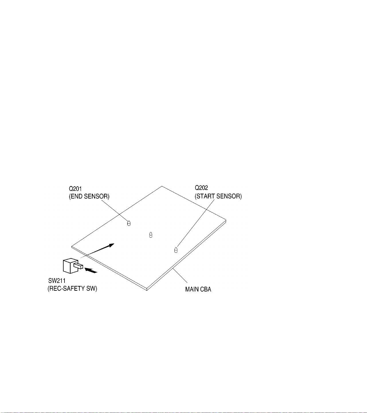
Caution:
Optical sensors are used for Tape Start and End Sensor on this equipment. Read this page carefully and
prepare as described on this page before starting to service; otherwise, the unit may operate unexpectedly.
Preparing:
Cover Q202 (START SENSOR) and Q201 (END SENSOR) with Insulation Tape or enter the service mode to
activate Sensor Inhibition automatically.
Note:
Avoid playing, rewinding or fast-forwarding the tape to its beginning or end, because both Tape End Sensors
are not active.
1. Turn power off.
2. Press the remote control keys in the following order:
2—> 7—> 1—> MUTE
3. While in the service mode, electrical adjustment mode may be selected by pressing the appropriate remote
control key as shown in the table below.

Key Adjustment Mode
MENU Picture adjustment mode : Press the MENU button to change from BRT
(Bright), *CNT (Contrast), *CLR (Color), *TNT(Tint) and *V-T. Press CH
UP/DOWN key to display Initial Value, Maximum and Minimum cyclically.
*Marked items are not necessary to adjust normally.
0 C-Trap adjustment mode: See adjustment instructions.
1 No need to use.
2 AGC/H adjustment mode: See adjustment instructions.
3 Auto AFT adjustment mode: See adjustment instructions
4 Auto record mode: Perform recording (15 Sec.)—>Stop—>Rewind (Zero
return) automatically.
5 Head switching point adjustment mode: See adjustment instructions.
6 No need to use.
7 Purity check mode: Shows Red, Green or Blue on the screen when the 7 key is
pressed.
8 H. Shift adjustment mode: See adjustment instructions.
9 V.size/V. shift adjustment: See adjustment instructions.
VOL? Cutoff adjustment mode. See adjustment instructions.
Caution:
1. The deck mechanism assembly is mounted on the Main CBA directly, and SW211 (REC-SAFETY SW) is
mounted on the Main CBA. When deck mechanism assembly is removed from the Main CBA due to
servicing, this switch can not be operated automatically.
Preparing:
1. To eject the tape, press the STOP/EJECT button on the unit (or Remote Control).
2. When you want to record during the Service mode, press the Rec button while depressing SW211 (RECSAFETY SW) on the Main CBA.
(Model CCC130AT01, CCC132AT01, CCC133AT01, CCC134 AT01,
CCC190AT31
How to Enter the Service Mode
Caution:
Optical sensors are used for Tape Start and End Sensor on this equipment. Read this page carefully and
prepare as described on this page before starting to service; otherwise, the unit may operate unexpectedly.
Preparing:
Cover Q202 (START SENSOR) and Q201 (END SENSOR) with Insulation Tape or enter the service mode to
activate Sensor Inhibition automatically.
Note:
Avoid playing, rewinding or fast forwarding the tape to its beginning or end, because both Tape End Sensors
are not active.
1. Turn power off.
2. Press the remote control keys in the following order:
2—> 7—> 1—> MUTE
3. While in the service mode, electrical adjustment mode may be selected by pressing the appropriate remote
control key as shown in the table below.
Key Adjustment Mode
MENU Picture adjustment mode : Press the MENU button to change from BRT
(Bright), *CNT (Contrast), *CLR (Color), *TNT(Tint) and *V-T. Press CH
UP/DOWN key to display Initial Value, Maximum and Minimum cyclically.
*Marked items are not necessary to adjust normally.
0 C-Trap adjustment mode: See adjustment instructions.
1 No need to use.
2 AGC/H adjustment mode: See adjustment instructions.
3 Auto AFT adjustment mode: See adjustment instructions
4 Auto record mode: Perform recording (15 Sec.)—>Stop—>Rewind (Zero
return) automatically.
5 Head switching point adjustment mode: See adjustment instructions.
6 No need to use.
7 Purity check mode: Shows Red, Green or Blue on the screen when the CH
UP/DOWN keys are pressed.
8 H. Shift adjustment mode: See adjustment.
9 V.size/V. shift adjustment: See adjustment.
Caution:
1. The deck mechanism assembly is mounted on the Main CBA directly, and SW211 (REC-SAFETY SW) is
mounted on the Main CBA. When deck mechanism assembly is removed from the Main CBA due to
servicing, this switch can not be operated automatically.
Preparing:
1. To eject the tape, press the STOP/EJECT button on the unit (or Remote Control).
2. When you want to record during the Service mode, press the Rec button while depressing SW211 (RECSAFETY SW) on the Main CBA.

CCC090AT01, CCC092AT01
Disassembly Flowchart
This flowchart indicates the disassembly steps for the cabinet parts, and the CBA in order to gain access to
item(s) to be serviced. When reassembling, follow the steps in reverse order. Bend, route and dress the cables
as they were.
Caution!
When removing the CRT, be sure to discharge the Anode Lead of the CRT with the CRT Ground Wire
before removing the Anode Cap.
Disassembly Method
STEP/
LOC.
NO.
[1] Rear Cabinet
[2] H.V. CBA
[3] Power
[4] Tray Chassis
[5] Deck Unit
[6] Main CBA
[7] CRT
1 2 3 4 5
PART REMOVAL
FIG.
NO.
1, 2
3, 5
3, 5
Supply CBA
3, 5
3, 6
3, 5
REMOVE/*UNLOCK/
RELEASE/UNPLUG/
UNCLAMP/DESOLDER
4(S-1), 1(S-2), (S-3), 2(S-4) 1
Anode Cap, CRT CBA,
CL501A, CN503, CN571,
CN575, CN602, 2(S-5)
Unclamp H/V CBA
CN1601, CN603, 2(S-6),
2(L-1), 4(S-7)
CN802 4
8(S-8) 5
3(S-9) 6
4
4(S-10) 7
NOTE
2
3

Note:
1 Order of steps in Procedure. When reassembling, follow the steps in reverse order.
These numbers are also used as the Identification (location) No. of parts in Figures.
2 Parts to be removed or installed.
3. Fig. No. showing Procedure of Part Location
4. Identification of part to be removed, unhooked, unlocked, released, unplugged, unclamped, or desoldered.
S=Screw, P=Spring, L=Locking Tab, CN=Connector, *=Unhook, Unlock, Release, Unplug, or Desolder.
2(S-2) = two Screws (S-2)
5 Refer to the following “Reference Notes in the Table.”
Reference Notes in the Table
1. Removal of the Rear Cabinet. Remove screws 4(S-1), 1(S-2), 2(S-3) and 2(S-4).
Caution!
Discharge the Anode Lead of the CRT with the CRT Ground Wire before removing the Anode Cap.
2. Removal of the H.V. CBA. Discharge the Anode Lead of the CRT with the CRT ground wire before
removing the Anode Cap. Remove screws 2(S-5). Disconnect the following: Anode Cap, CRT CBA,
CL501A, CN503, CN571, CN575, CN602.
3. Removal of the Power Supply CBA. Disconnect CN1601 and CN603. Remove screws 2(S-6). Slide the
Power Supply CBA Holder backward. Remove screws 4(S-7) and release 2(L-1). Pull the Power Supply
CBA backward.
4. Removal of the Tray chassis. Disconnect CN802. Slide Tray chassis backward.
5. Removal of the Deck Unit. Remove screws 8(S-8). Lift up the Deck Unit.
6. Removal of the Main CBA. Remove screws 3(S-9).
7. Removal of the CRT. Remove screws 4(S-10) and pull the CRT backward.


CCC130AT01, CCC132AT01, CCC192AT31, CC19C1MG31
Disassembly Flowchart
This flowchart indicates the disassembly steps for the cabinet parts, and the CBA in order to gain access to
item(s) to be serviced. When reassembling, follow the steps in reverse order. Bend, route and dress the cables
as they were.
Caution!
When removing the CRT, be sure to discharge the Anode Lead of the CRT with the CRT Ground Wire
before removing the Anode Cap.
Disassembly Method
STEP/
LOC.
NO.
[1] Rear Cabinet
[2] H.V. CBA
[3] Tray Chassis
[4] Deck Unit
[5] Main CBA
[6] CRT
1 2 3 4 5
PART REMOVAL
FIG.
NO
1, 2, 3, 4
5, 7
With Holder)
5
5
5,7
4
REMOVE/*UNLOCK/
RELEASE/UNPLUG/
UNCLAMP/DESOLDER
4(S-1), (S-2) 1
Anode Cap, CRT CBA,
L501A,CN503, CN571,
CN575, CN602 2(S-3), 2(L-1)
CN601, CN801 3
9( S-4) 4
5(S-5) 5
4(S-6) 6
NOTE
2

Note :
1 Order of steps in Procedure. When reassembling, follow the steps in reverse order.
These numbers are also used as the Identification (location) No. of parts in Figures.
2 Parts to be removed or installed.
3. Fig. No. showing Procedure of Part Location
4. Identification of part to be removed, unhooked, unlocked, released, unplugged, unclamped, or desoldered.
S=Screw, P=Spring, L=Locking Tab, CN=Connector, *=Unhook, Unlock, Release, Unplug, or Desolder.
2(S-2) = two Screws (S-2)
5 Refer to the following “Reference Notes in the Table.”
Reference Notes in the Table
1. Removal of the Rear Cabinet. Remove screws 4(S-1) and 1(S-2).
Caution!
Discharge the Anode Lead of the CRT with the CRT Ground Wire before removing the Anode Cap.
2. Removal of the H.V. CBA with holder. Discharge the Anode Lead of the CRT with the CRT ground wire
before removing the Anode Cap.
Disconnect the following: Anode Cap, CRT CBA, CL501A, CN503, CN571, CN575 and CN602. Remove
2(S-3). Unlock 2(L-1). Pull the HV CBA backward.
3. Removal of the Tray chassis. Disconnect CN601 and CN801. Pull the tray chassis backward.
4. Removal of the Deck Unit. Remove 7(S-4) and 1 (S-5). Lift up the Deck Unit.
5. Removal of the Main CBA. Remove 6(S-6). Lift up the Main CBA.
6. Removal of the CRT. Remove 4(S-7) and pull the CRT backward.


CCC190AT31
Disassembly Flowchart
This flowchart indicates the disassembly steps for the cabinet parts, and the CBA in order to gain access to
item(s) to be serviced. When reassembling, follow the steps in reverse order. Bend, route and dress the cables
as they were.
Caution!
When removing the CRT, be sure to discharge the Anode Lead of the CRT with the CRT Ground Wire
before removing the Anode Cap.
Disassembly Method
STEP/
LOC.
NO.
FIG.
[1] Rear Cabinet
[2] H.V. CBA
[3] Tray
[4] Deck Unit
[5] Main CBA
[6] CRT
1 2 3 4 5
Note :
1 Order of steps in Procedure. When reassembling, follow the steps in reverse order.
These numbers are also used as the Identification (location) No. of parts in Figures.
2 Parts to be removed or installed.
PART REMOVAL
REMOVE/*UNLOCK/
NO.
1, 2, 3, 4
5
(With Holder)
5
Chassis
5
5
4
RELEASE/UNPLUG/
UNCLAMP/DESOLDER
4(S-1), (S-2) 1
Anode Cap,
CRT CBA, CL501A, CN503,
CN571, CN575, CN602
2(S-3), 2(L-1)
CN601, CN801 3
9( S-4) 4
5(S-5) 5
4(S-6) 6
NOTE
2

3. Fig. No. showing Procedure of Part Location
4. Identification of part to be removed, unhooked, unlocked, released, unplugged, unclamped, or desoldered.
S=Screw, P=Spring, L=Locking Tab, CN=Connector, *=Unhook, Unlock, Release, Unplug, or Desolder.
2(S-2) = two Screws (S-2)
5 Refer to the following “Reference Notes in the Table.”
Reference Notes in the Table
1. Removal of the Rear Cabinet. Remove screws 4(S-1) and 1(S-2)
Caution!
Discharge the Anode Lead of the CRT with the CRT Ground Wire before removing the Anode Cap.
2. Removal of the H.V. CBA with Holder. Discharge the Anode Lead of the CRT with the CRT ground wire
before removing the Anode Cap.
Disconnect the following: Anode Cap, CRT CBA, CL501A, CN503, CN571, CN575, CN602. Remove 2(S-3).
Unlock 2(L-1). Pull the H.V. CBA backward.
3. Removal of the Tray chassis. Disconnect CN601 and CN801. Pull the Tray chassis backward.
4. Removal of the Deck Unit. Remove 7(S-4) and 1(S-5). Lift up the Deck Unit.
5. Removal of the Main CBA. Remove 6(S-6) Lift up the Main CBA.
6. Removal of the CRT. Remove screws 4(S-7) and pull the CRT backward.


CCC133AT01, CCC134AT01
Disassembly Flowchart
This flowchart indicates the disassembly steps for the cabinet parts, and the CBA in order to gain access to
item(s) to be serviced. When reassembling, follow the steps in reverse order. Bend, route and dress the cables
as they were.
Caution!
When removing the CRT, be sure to discharge the Anode Lead of the CRT with the CRT Ground Wire
before removing the Anode Cap.
Disassembly Method
STEP/
LOC. NO.
FIG. NO. REMOVE/*UNLOCK/
[1] Rear Cabinet
[2] H.V. CBA
[3] Tray Chassis
[4] Deck Unit
[5] Main CBA
[6] CRT
1 2 3 4 5
Note :
1 Order of steps in Procedure. When reassembling, follow the steps in reverse order.
These numbers are also used as the Identification (location) No. of parts in Figures.
2 Parts to be removed or installed.
3. Fig. No. showing Procedure of Part Location
PART REMOVAL
RELEASE/UNPLUG/
UNCLAMP/DESOLDER
1, 2, 3, 4
5
(With Holder)
5
5
3, 5
4
4(S-1), (S-2) 1
Anode Cap, CRT CBA,
CL501A, CN503,
CN571, CN575, CN602
2(S-3), 2(L-1)
CN601, CN801 3
9(S-4) 4
5(S-5) 5
4(S-6) 6
NOTE
2

4. Identification of part to be removed, unhooked, unlocked, released, unplugged, unclamped, or desoldered.
S=Screw, P=Spring, L=Locking Tab, CN=Connector, *=Unhook, Unlock, Release, Unplug, or Desolder.
2(S-2) = two Screws (S-2)
5 Refer to the following “Reference Notes in the Table.”
Reference Notes in the Table
1. Removal of the Rear Cabinet. Remove screws 4(S-1) and 1(S-2).
Caution!
Discharge the Anode Lead of the CRT with the CRT Ground Wire before removing the Anode Cap.
2. Removal of the H.V. CBA with Holder. Discharge the Anode Lead of the CRT with the CRT ground wire
before removing the Anode Cap.
Disconnect the following: Anode Cap, CRT CBA, CL501A, CN503, CN571, CN575, CN602. Remove 2(S-3).
Unlock 2(L-1). Pull the H.V. CBA backward.
3. Removal of the Tray chassis. Disconnect CN601 and CN801. Pull the Tray chassis backward.
4. Removal of the Deck Unit. Remove 9(S-4). Lift up the Deck Unit.
5. Removal of the Main CBA. Remove 5(S-5). Lift up the Main CBA.
6. Removal of the CRT. Remove screws 4(S-6) and pull the CRT backward.


Alignment Procedures of Mechanism - CCC090, CCC092
The following procedures describe how to align the individual gears and levers that make up the tape
loading/unloading mechanism. Since information about the state of the mechanism is provided to the System
Control Circuit only through the Mode Switch, it is essential that the correct relationship between individual
gears and levers be maintained.
All alignments are to be performed with the mechanism in Eject mode, in the sequence given. Each procedure
assumes that all previous procedures have been completed.
IMPORTANT:
If any one of these alignments is not performed properly, even if off by only one tooth, the unit will unload or
stop and it may result in damage to the mechanical or electrical parts.

Alignment points in Eject Position
Alignment 1
Loading Arm, S and T Assembly
Install Loading Arm S and T Assembly so that their triangle marks point to each other as shown in Fig. AL2.
Alignment 2
Mode Gear
Keeping the two triangles pointing at each other, install the Loading Arm T Assembly so that the last tooth of the
gear meets the most inside teeth of the Mode Gear. See Fig. AL2.
Alignment [a]
Tape Guide Assembly
Measurement of the screw must be as specified in Fig. AL3.

Alignment 3
Cam Gear (A), Rack Assembly
Install the Rack Assembly so that the first tooth on the gear of the Rack Assembly meets the first groove on the
Cam Gear (A) as shown in Fig. AL4.

Mechanical Alignment Procedures
Explanation of alignment for the tape to correctly run starts on the next page. Refer to the information below on
this page if a tape gets stuck, for example, in the mechanism due to some electrical trouble of the unit.
Service Information
Method for Manual Tape Loading/Unloading
To load a cassette tape manually:
1. Disconnect the AC plug.
2. Remove the Top Case and Front Assembly.
3. Insert a cassette tape. Though the tape will not be automatically loaded, make sure that the cassette tape is
all the way in at the inlet of the Cassette Holder. To confirm this, lightly push the cassette tape further in and
see if the tape comes back out, by a spring motion, just as much as you have pushed in.
4. Turn the LDG Belt in the appropriate direction shown in Fig. M1 for a minute or two to complete this task.
To unload a cassette tape manually:
1. Disconnect the AC plug.
2. Remove the Top Case and Front Assembly.
3. Make sure that the Moving guide preparations are in the Eject Position.
4. Turn the LDG Belt in the appropriate direction shown in Fig. M1 until the Moving guide preparations come to
the Eject Position. Stop turning when the preparations begin clicking or can not be moved further. However,
the tape will be left wound around the cylinder.
5. Turn the LDG Belt in the appropriate direction continuously, and the cassette tape will be ejected. Allow a
minute or two to complete this task.

Method to place the Cassette Holder in the tape-loaded position without a
cassette tape
1. Disconnect the AC Plug.
2. Remove the Top Case and Front Assembly.
3. Turn the LDG Belt in the appropriate direction shown in Fig. M1. Release the locking tabs shown in Fig. M1
and continue turning the LDG Belt until the Cassette Holder comes to the tape-loaded position. Allow a
minute or two to complete this task.
Note: To do these alignment procedures, make sure that the Tracking Control Circuit is set to the center
position every time a tape is loaded or unloaded.
Equipment required:
Dual Trace Oscilloscope
VHS Alignment Tape (VFMS0001H6)
Guide Roller Adj. Screwdriver
X-Value Adj. Screwdriver
Note: Before starting this Mechanical Alignment, do all Electrical Adjustment procedures.
Preliminary/Final Checking and Alignment of Tape Path
Purpose: To make sure that the tape path is well stabilized.
Symptom of Misalignment: If the tape path is unstable, the tape will be damaged.
Note: Do not use an Alignment Tape for this procedure. If the unit is not correctly aligned, the tape may be
damaged.
1. Play back a blank cassette tape and check to see that the tape runs without creasing at Guide Rollers [2]
and [3], and at points A and B on the lead surface. (Refer to Fig M3 and M4.)

2. If creasing is apparent, align the height of the guide rollers by turning the top of Guide Rollers [2] and [3]
with a Guide Roller Adj. Screwdriver. (Refer to Fig. M3 and M5.)
Note: Beneath each Guide Roller, there is a small screw. (Refer to Fig. M5.) This screw works to apply
adequate torque to the shaft of each Guide Roller so that the Guide Roller turns properly. Even when
adjusting the height of the Guide Roller(s), do not touch these two small screws.
3. Check to see that the tape runs without creasing at Take-up Guide Post [4] or without snaking between
Guide Roller [3] and AC Head.
(Fig. M3 and M5)
4. If creasing or snaking is apparent, adjust the Tilt Adj. Screw of the AC Head. (Fig. M6)

X Value Alignment
Purpose: To align the Horizontal Position of the Audio/Control/Erase Head.
Symptom of Misalignment: If the Horizontal Position of the Audio/Control/Erase Head is not properly aligned,
maximum envelope cannot be obtained at the Neutral position of the Tracking Control Circuit.
1. Connect the oscilloscope to J36 [Model CCC090] or J139 [Models CCC130, CCC132, CCC190, CCC192,
CCC092, CCC134, CCC194, CCC19C] (C-PB) and J31 [Model CCC090] or J192 [Models CCC130,
CCC132, CCC190, CCC192, CCC092, CCC134, CCC194, CCC19C] (CTL) on the Main CBA. Use J69
[Model A] or J190 [Models CCC130, CCC132, CCC190, CCC192, CCC092, CCC134, CCC194, CCC19C]
(RF-SW) as a trigger.
2. Play back the Gray Scale of the Alignment Tape (VFMS0001H6) and confirm that the PB FM signal is
present.
3. Set the Tracking Control Circuit to the center position by pressing the CH UP button then the PLAY button
on the VCR.
4. Use the X-Value Adj. Screwdriver so that the PB FM signal at J36 [Model CCC090] or J139 [Models
CCC130, CCC132, CCC190, CCC192, CCC092, CCC134, CCC194, CCC19C] (C-PB) is maximum. (Fig.
M6)
5. Press CH UP button on the VCR until the CTL waveform has shifted by approx. +2msec. Make sure that the
envelope is simply attenuated (shrinks in height) during this process so that you will know the envelope has
been at its peak.
6. Press CH DOWN button on the VCR until the CTL waveform has shifted from its original position (not the
position achieved in step 5, but the position of CTL waveform in step 4) by approximately -2msec. Make
sure that the envelope is simply attenuated (shrinks in height) once CTL waveform passes its original
position and is further brought in the minus direction.
7. Set the Tracking Control Circuit to the center position by pressing the CH UP button and then the PLAY
button on the VCR.

Checking/Adjustment of Envelope Waveform
Purpose: To achieve a satisfactory picture and precise tracking.
Symptom of Misalignment: If the envelope output is poor, noise will appear in the picture. The tracking will
then lose precision and the playback picture will be distorted by any slight variation of the Tracking Control
Circuit.
1. Connect the oscilloscope to J36 [Model CCC090] or J139 [Models CCC130, CCC132, CCC190, CCC192,
CCC092, CCC134, CCC194, CCC19C] (C-PB) on the Main CBA. Use J69 [Model CCC090] or J190
[Models CCC130, CCC132, CCC190, CCC192, CCC092, CCC134, CCC194, CCC19C] (RF-SW) as a
trigger.
2. Play back the Gray Scale on the Alignment Tape (VFMS0001H6). Set the Tracking Control Circuit to the
center position by pressing the CH UP and then the PLAY button on the VCR. Adjust the height of Guide
Rollers [2] and [3] watching the oscilloscope display so that the envelope becomes as flat as possible. To do
this adjustment, turn the top of the Guide Roller with the Guide Roller Adj. Screwdriver.
3. If the envelope is as shown in Fig. M7, adjust the height of Guide Roller [2] (Refer to Fig. M3) so that the
waveform looks like the one shown in Fig. M9.
4. If the envelope is as shown in Fig. M8, adjust the height of Guide Roller [3] (Refer to Fig. M3) so that the
waveform looks like the one shown in Fig. M9.
5. When Guide Rollers [2] and [3] (Refer to Fig. M3) are aligned properly, there is no envelope drop either at
the beginning or end of track as shown in Fig. M9.

Note: Upon completion of the adjustment of Guide Rollers [2] and [3] (Refer to Fig. M3), check the X Value by
pushing the CH UP or DOWN buttons alternately, to check the symmetry of the envelope. Check the
number of pushes to ensure center position. The number of pushes UP to achieve 1/2 level of envelope
should match the number of pushes DOWN from center. If required, redo the “X Value Alignment.”
Azimuth Alignment of Audio/Control/Erase Head
Purpose: To correct the Azimuth alignment so that the Audio/Control/Erase Head meets tape tracks properly.
Symptom of Misalignment: If the position of the Audio/Control/Erase Head is not properly aligned, the Audio
S/N Ratio or Frequency Response will be poor.
1. Connect the oscilloscope to the audio output jack on the rear side of the deck.
2. Play back the alignment tape (VFMS0001H6) and confirm that the audio signal output level is 6 kHz.
3. Adjust Azimuth Adj. Screw so that the output level on the AC Voltmeter or the waveform on the oscilloscope
is at maximum. (Fig. M6)
Notes:
1. The video head surface is made of very hard material, but since it is very thin, avoid cleaning it vertically.
2. Wait for the cleaned part to dry thoroughly before operating the unit.
3. Do not reuse a stained head cleaning stick or a stained chamois cloth.

Service Adjustments for CCC090AT01, CCC092AT01
General Note: “CBA” is abbreviation for “Circuit Board Assembly.”
Note: Electrical adjustments are required after replacing circuit components and certain mechanical parts. It
is important to perform these adjustments only after all repairs and replacements have been
completed. Also, do not attempt these adjustments unless the proper equipment is available.
Test Equipment Required
1. NTSC Pattern Generator (Color Bar w/White Window, Red Color, Dot Pattern, Gray Scale, Monoscope,
Multi-Burst)
2. AC Milli Voltmeter (RMS)
3. Alignment Tape (VFMS0001H6), Blank Tape
4. DC Voltmeter
5. Oscilloscope: Dual-trace with 10:1 probe,
V-Range: 0.001~50V/Div,
F-Range: DC~AC-60MHz
6. Frequency Counter
7. Plastic Tip Driver
How to Setup the Service mode
1. Use the remote control unit.
2. Turn the power off.
3. Press “2" ”7" “1" ”MUTE" button on the remote control unit in 5 seconds.

DC 117V (+B) Adjustment (AC Power)
Purpose: To obtain correct operation.
Symptom of Misadjustment: The picture is dark and unit does not operate correctly.
Test Point Adjustment Point Mode Input
J553(+B)
J563 (GND)
Tape M. EQ. Spec.
—- DC Voltmeter +117 ± 0.5V DC
Note: J553(+B), J563(GND) —- H.V. CBA
VR1620 —- Power Supply CBA
1. Connect the unit to AC Power Outlet.
2. Connect DC Voltmeter to J553(+B) and J563(GND).
3. Adjust VR1620 so that the voltage of J553(+B) becomes +117 ± 0.5V DC.
VR1620 —- —-

DC 117V (+B) Adjustment (DC Power)
Purpose: To obtain correct operation.
Symptom of Misadjustment: The picture is dark and unit does not operate correctly.
Test Point Adjustment Point Mode Input
J553 (+B)
J563 (GND)
Tape M. EQ. Spec.
—- DC Voltmeter +117 ± 0.5V DC
Note: J553 (+B), J563 (GND) —- H.V. CBA VR1951 —- Power Supply CBA
1. Input 13.2V DC to DC Jack.
2. Connect DC Voltmeter to J553 (+B) and J563 (GND).
3. Adjust VR1951 so that the voltage of J553(+B) becomes +117 ± 0.5V DC.
VR1951 —- —-
Auto AFT (VCO) Adjustment
Purpose: To operate AFT correctly.
Symptom of Misadjustment: AFT does not work correctly and/or synchronization is faulty.
Test Point Adjustment Point Mode Input
—- —- VIDEO —-
Tape M. EQ. Spec.
—- —- —-
1. Set the unit to the VIDEO mode with no signal input.
2. Enter the Service mode. Then press number “3" button on the remote control unit
3. If the screen color changes to “Green” then this adjustment is finished.
4. If the screen color changes to “Red” then this adjustment is failed. Repeat steps 1 and 2 or check
relative circuit or parts (IC).

TV AGC Adjustment
Purpose: Set AGC (Auto Gain Control) Level.
Symptom of Misadjustment: AGC does not synchronize correctly when RF input level is too weak and picture
distortion may occur if it is too strong.
Test Point Adjustment Point Mode Input
J1 CH. up/down
buttons
Tape M. EQ. Spec.
—- Pattern Generator
DC Voltmeter
Notes: J1 —- Main CBA
1. Enter the Service mode. Then press number “2" button on the remote control unit.
2. Receive the Color Bar signal for channel 4 (67.25MHz). (RF Input Level: 60dBmV)
3. Press CH. up/down buttons so that the voltage of J1 becomes +2.8V0.3V DC.
(Tuner Type No. TEDH9X203A)
Press CH. up/down buttons so that the voltage of J1 becomes +2.8V ± 0.3V DC. (Tuner Type No.
B8055AR)
Press CH. up/down buttons so that the voltage of J1 becomes +2.8V ± 0.3V DC. (Tuner Type No.
NJH3022U254)
4. Turn the power off and on again.
—- Color Bar
67.25MHz
60dBmV
+2.8V ± 0.3VDC
+2.8V ± 0.3VDC
+2.8V ± 0.3VDC
H Adjustment
Purpose: To get correct horizontal position and size of screen image.
Symptom of Misadjustment: Horizontal position and size of screen image may not be properly displayed.
Test Point Adjustment Point Mode Input
R583 CH up/down buttons
Tape M. EQ. Spec.
—— Frequency Counter 15.734kHz ± 300Hz
Note: R583 —- Main CBA
1. Connect frequency counter to R583.
2. Set the unit to the VIDEO mode and no input is necessary. Enter the Service mode.
3. Operate the unit for at least 20 minutes.
4. Press “2" button on the remote control unit and select H-Adj Mode. (Press ”2" button, then display will
change H-Adj and AGC.)
5. Press CH up/down buttons on the remote control unit so that the display will change “0" to ”7."
At this moment, choose display “0" to ”7" when the frequency counter display is closest to 15.734kHz ±
300Hz.
6. Turn the power off and on again.
VIDEO ——

C-Trap Adjustment
Purpose: To get minimum leakage of the color signal carrier.
Symptom of Misadjustment: If C-Trap Adjustment is incorrect, stripes will appear on the screen.
Test Point Adjustment Point Mode Input
R502
TOP SIDE
(B-Out)
Tape M. EQ. Spec.
—— Oscilloscope
CH up/down
buttons
—- Color Bar
200mV P-P
Note: R502 TOP SIDE (B-Out)—- Main CBA
1. Connect Oscilloscope to R502 TOP SIDE.
2. Input a color bar signal from RF input. Enter the Service mode.
3. Press “0" button on the remote control unit and select C-TRAP Mode.
4. Press CH up/down buttons on the remote control unit so that the carrier leakage B-Out (3.58MHz) value
becomes minimum on the oscilloscope.
5. Turn the power off and on again.
V. Size Adjustment
Purpose: To obtain correct vertical height of screen image.
Symptom of Misadjustment: If V. Size is incorrect, vertical height of image on the screen may not be properly
displayed.
Test Point Adjustment Point Mode Input
—- CH up/down
buttons
Tape M. EQ. Spec.
—- Pattern Generator 90 ± 5%
Note:
1. Enter the Service mode. Press “9" button on the remote control unit and select V-S Mode. (Press ”9"
button then display will change to V-P and V-S).
2. Input monoscope pattern.
3. Press CH up/down buttons on the remote control unit so that the monoscope pattern is 90 ± 5% of
display size and the circle is round.
—- Monoscope

V. Shift Adjustment
Purpose: To obtain correct vertical position of screen image.
Symptom of Misadjustment: If V. position is incorrect, vertical position of image on the screen may not be
properly displayed.
Test Point Adjustment Point Mode Input
—- CH up/down
buttons
Tape M. EQ. Spec.
—- Pattern Generator 90 ± 5%
Note:
1. Enter the Service mode. Press “9" button on the remote control unit and select V-P Mode. (Press ”9"
button then display will change to V-P and V-S).
2. Input monoscope pattern.
3. Press CH up/down buttons on the remote control unit so that the top and bottom of the monoscope
pattern are equal to each other.
—- Monoscope
H. Shift Adjustment
Purpose: To obtain correct horizontal position and size of screen image.
Symptom of Misadjustment: Horizontal position and size of screen image may not be properly displayed.
Test Point Adjustment Point Mode Input
—- CH up/down
buttons
Tape M. EQ. Spec.
—- Pattern Generator 90 ± 5%
Note:
1. Enter the Service mode. Press “8" button on the remote control unit and select H-P Mode.
2. Input monoscope pattern.
3. Press CH up/down buttons on the remote control unit so that the left and right side of the monoscope
pattern are equal to each other.
4. Turn the power off and on again.
—- Monoscope

Cut-off Adjustment
Purpose: To adjust the beam current of R, G, B, and screen voltage.
Symptom of Misadjustment: White color may be reddish, greenish or bluish.
Test Point Adjustment Point Mode Input
—- Screen-Control Ext. Black Raster /
White Raster
Tape M. EQ. Spec.
—-
Pattern Generator
See Reference Notes below.
Note: Screen Control FBT —- H/V CBA
F.B.T = Flyback Transformer
Use the Remote Control Unit
1. Degauss the CRT and allow CRT to operate for 20 minutes before starting the alignment.
2. Set the screen control to minimum position. Input the Black raster signal from RF input.
3. Enter the Service mode. Dimmed horizontal line appears on the CRT.
4. Press the “VOL down” button. (Press “VOL down” then display will change CUT OFF/DRIVE, VCO
adjustment, Analog OSD adjustment).
5. Choose CUT OFF/DRIVE mode then press “1" button. This adjustment mode is CUT OFF (R).
6. Press the “CH up/down” button until the horizontal line becomes white.
7. Choose CUT OFF/DRIVE mode then press “2" button. This adjustment mode is CUT OFF (G). Press
”CH up/down “ until the horizontal line becomes white.
8. Choose CUT OFF/DRIVE mode then press “3" button. This adjustment mode is CUT OFF (B). Press
”CH up/down “ until the horizontal line becomes white.
9. Input the White Raster Signal from Video In.
10. Choose CUT OFF/DRIVE mode then press “4.” Adjust the RED DRIVE as needed with the CH
up/down buttons.
11. Choose CUT OFF/DRIVE mode then press “5.” Adjust the BLUE DRIVE as needed with the CH
up/down buttons.
12. Turn the power off and on again.

Sub-Brightness Adjustment
Purpose: To get proper brightness.
Symptom of Misadjustment: If Sub-Brightness is incorrect, proper brightness cannot be obtained by adjusting
the Brightness Control.
Test Point Adjustment Point Mode Input
—- CH up/down
buttons
Tape M. EQ. Spec.
—- Pattern Generator
—- SYMPTE 7.5 IRE
See below
Note: SYMPTE Setup level —- 7 IRE
1. Enter the Service mode. Then input SYMPTE signal from RF input.
2. Press MENU button. (Press MENU button then display will change B R T, C N T, T N T, V-T and SHP).
Select BRT and press CH up/down buttons so that the bar is just visible.
3. Turn the power off and on again.
Focus Adjustment
Purpose: Set the optimum Focus.
Symptom of Misadjustment: If Focus Adjustment is incorrect, blurred images are shown on the display.
Test Point Adjustment Point Mode Input
—- Focus Control —- Monoscope
Tape M. EQ. Spec.
—- Pattern Generator See below.
Note: Focus VR (FBT) —- H/V CBA
FBT= Flyback Transformer
1. Operate the unit more than 30 minutes
2. Face the unit to the East and degauss the CRT using a Degaussing Coil.
3. Input the monoscope pattern.
4. Adjust the Focus Control on the FBT to obtain clear picture.

Head Switching Position Adjustment
Purpose: Determine the Head Switching Point during Play back.
Symptom of Misadjustment: May cause Head Switching Noise or Vertical Jitter in the picture.
Note: Unit reads Head Switching Position automatically and displays it on the screen (Upper Left Corner).
1. Playback test tape (VFMS0001H6).
2. Enter the Service mode. Then press the number “5" button on the remote control unit.
3. The Head Switching position will display on the screen; if adjustment is necessary follow step 4. 6.5H
(412.7µs) is preferable.
4. Press “CH up” or “CH down” button on the remote control unit if necessary. The value will be changed
in 0.5H steps up or down. Adjustable range is up to 9.5H. If the value is beyond adjustable range, the
display will change as:
Lower out of range; 0.0H
Upper out of range; -.-H
5. Turn the power off and on again.
The following 2 adjustments normally are not attempted in the field. They should be done only when
replacing the CRT then adjust as a preparation.

Purity Adjustment
Purpose: To obtain pure color.
Symptom of Misadjustment: If Color Purity Adjustment is incorrect, large areas of color may not be properly
displayed.
Test Point Adjustment Point Mode Input
—- Deflection Yoke
Purity Magnet
Tape M. EQ. Spec.
—-
Pattern Generator
—- ——
See below.
1. Set the unit facing east.
2. Operate the unit for over 30 minutes before adjusting.
3. Fully degauss the unit using an external degaussing coil.
4. Enter the Service mode. Press “7" button on the remote control so that red color appear.
5. Loosen the screw on the Deflection Yoke Clamper and pull the Deflection Yoke back away from the
screen. (See Fig. 6)
6. Loosen the Ring Lock and adjust the Purity Magnets so that a red field is obtained at the center of the
screen. Tighten Ring Lock. (See Fig. 5, 6)
7. Slowly push the Deflection Yoke toward the bell of the CRT and set it where a uniform red field is
obtained.
8. Tighten the clamp screw on the Deflection Yoke.


Convergence Adjustment
Purpose: To obtain proper convergence of red, green and blue beams.
Symptom of Misadjustment: If Convergence Adjustment is incorrect, the edge of white letters may have color
edges.
Test Point Adjustment Point Mode Input
—-
Tape M. EQ. Spec.
—- Pattern Generator See below.
1. Set the unit to the AUX Mode which is located before CH2 then input a Dot or crosshatch pattern.
2. Loosen the Ring Lock and align red with blue dots or Crosshatch at the center of the screen by rotating
(RB) C.P. Magnets.
3. Align red/blue with green dots at the center of the screen by rotating (RB-G) C.P. Magnet.
4. Fix the C.P. Magnets by tightening the Ring Lock.
5. Remove the DY Wedges and slightly tilt the Deflection Yoke horizontally and vertically to obtain the best
overall convergence.
6. Fix the Deflection Yoke by carefully inserting the DY Wedges between CRT and Deflection Yoke.
C.P. Magnet (RB),
C.P. Magnet (RB-G),
Deflection Yoke
—- Dot Pattern
or
Crosshatch

Service Adjustments for CCC130AT01 & CCC132AT01
General Note: “CBA” is abbreviation for “Circuit Board Assembly.”
Note: Electrical adjustments are required after replacing circuit components and certain mechanical parts. It
is important to perform these adjustments only after all repairs and replacements have been
completed. Also, do not attempt these adjustments unless the proper equipment is available.
Test Equipment Required
1. NTSC Pattern Generator (Color Bar w/White Window, Red Color, Dot Pattern, Gray Scale, Monoscope,
Multi-Burst)
2. AC Milli Voltmeter (RMS)
3. Alignment Tape (VFMS0001H6), Blank Tape
4. DC Voltmeter
5. Oscilloscope: Dual-trace with 10:1 probe,
V-Range: 0.001~50V/Div,
F-Range: DC~AC-60MHz
6. Frequency Counter
7. Plastic Tip Driver
How to Setup the Service mode
1. Use the remote control unit.
2. Turn the power off.
3. Press “2" ”7" “1" ”MUTE" button on the remote control unit in 5 seconds.

DC 105V (+B) Adjustment
Purpose: To obtain correct operation.
Symptom of Misadjustment: The picture is dark and unit does not operate correctly.
Test
Point
J261 (+B)
J281 (GND)
Tape M. EQ. Spec.
—- DC Voltmeter +105 ± 0.5VDC
Note: J261(+B), J281(GND), VR601 —- Main CBA
1. Connect the unit to AC Power Outlet.
2. Connect DC Voltmeter to J261(+B) and J281(GND).
3. Adjust VR601 so that the voltage of J261(+B) becomes +105 ± 0.5V DC. (A)
Adjustment
Point
VR601
Mode Input
—- —-

Auto AFT (VCO) Adjustment
Purpose: To operate AFT correctly.
Symptom of Misadjustment: AFT does not work correctly and/or synchronization is faulty.
Test
Point
—- —- VIDEO —Tape M. EQ. Spec.
—- —- —-
1. Set the unit to the VIDEO mode with no signal input.
2. Enter the Service mode. Then press number “3" button on the remote control unit.
3. If the screen color changes to “Green” then this adjustment is finished.
4. If the screen color changes to “Red” then this adjustment is failed. Repeat steps 1 and 2 or check
relative circuit or parts (IC).
Adjustment
Point
Mode Input
TV AGC Adjustment
Purpose: Set AGC (Auto Gain Control) Level.
Symptom of Misadjustment: AGC does not synchronize correctly when RF input level is too weak and picture
distortion may occur if it is too strong.
Test Point Adjustment Point Mode Input
J138
Tape M. EQ. Spec.
—-
CH. up/down
buttons
Pattern Generator
DC Voltmeter
—- Color Bar
67.25MHz
60dBmV
+2.8V ± 0.3VDC
+2.8V ± 0.3VDC
+2.8V ± 0.3VDC
Notes: J138 —- Main CBA
1. Enter the Service mode. Then press number 2 button on the remote control unit.

2. Receive the Color Bar signal for channel 4 (67.25MHz). (RF Input Level: 60dBmV)
3. Press CH. up/down buttons so that the voltage of J138 becomes +2.8V ± 0.3V DC.
(Tuner Type No. TEDH9X203A)
4. Press CH. up/down buttons so that the voltage of J138 becomes +2.8V ± 0.3V DC.
(Tuner Type No. B8055AR)
5. Press CH. up/down buttons so that the voltage of J138 becomes +2.8V ± 0.3V DC.
(Tuner Type No. NJH3022U254)
6. Turn the power off and on again.
H Adjustment
Purpose: To get correct horizontal position and size of screen image.
Symptom of Misadjustment: Horizontal position and size of screen image may not be properly displayed.
Test Point Adjustment Point Mode Input
R583 CH up/down buttons VIDEO ——
Tape M. EQ. Spec.
—— Frequency Counter 15.734kHz ± 300Hz
Note: R583 —- Main CBA
1. Connect frequency counter to R583.
2. Set the unit to the VIDEO mode and no input is necessary. Enter the Service mode.
3. Operate the unit for at least 20 minutes.
4. Press “2" button on the remote control unit and select H-Adj Mode. (Press ”2" button, then display will
change H-Adj and AGC.)
5. Press CH up/down buttons on the remote control unit so that the display will change “0" to ”7."
At this moment, choose display “0" to ”7" when the frequency counter display is closest to
15.734kHz ± 300Hz.
6. Turn the power off and on again.

C-Trap Adjustment
Purpose: To get minimum leakage of the color signal carrier.
Symptom of Misadjustment: If C-Trap Adjustment is incorrect, stripes will appear on the screen.
Test Point Adjustment Point Mode Input
J070
B-Out)
Tape M. EQ. Spec.
—— Oscilloscope
CH up/down
buttons
—- Color Bar
200mV P-P
Note: J070 (B-Out)—- Main CBA
1. Connect Oscilloscope to J070.
2. Input a color bar signal from RF input. Enter the Service mode.
3. Press “0" button on the remote control unit and select C-TRAP Mode.
4. Press CH up/down buttons on the remote control unit so that the carrier leakage B-Out (3.58MHz) value
becomes minimum on the oscilloscope.
5. Turn the power off and on again.
V. Size Adjustment
Purpose: To obtain correct vertical height of screen image.
Symptom of Misadjustment: If V. Size is incorrect, vertical height of image on the screen may not be properly
displayed.
Test Point Adjustment Point Mode Input
—- CH up/down
buttons
Tape M. EQ. Spec.
—- Pattern Generator 90 ± 5%
1. Enter the Service mode. Press “9" button on the remote control unit and select V-S Mode. (Press ”9"
button then display will change to V-P and V-S).
2. Input monoscope pattern.
3. Press CH up/down buttons on the remote control unit so that the monoscope pattern is 90 ± 5% of
display size and the circle is round.
—- Monoscope

V. Shift Adjustment
Purpose: To obtain correct vertical position of screen image.
Symptom of Misadjustment: If V. position is incorrect, vertical position of image on the screen may not be
properly displayed.
Test Point Adjustment Point Mode Input
—- CH up/down
buttons
Tape M. EQ. Spec.
—- Pattern Generator 90 ± 5%
Note:
1. Enter the Service mode. Press “9" button on the remote control unit and select V-P Mode. (Press ”9"
button then display will change to V-P and V-S).
2. Input monoscope pattern.
3. Press CH up/down buttons on the remote control unit so that the top and bottom of the monoscope
pattern are equal to each other.
—- Monoscope
H. Shift Adjustment
Purpose: To obtain correct horizontal position and size of screen image.
Symptom of Misadjustment: Horizontal position and size of screen image may not be properly displayed.
Test Point Adjustment Point Mode Input
—- CH up/down
buttons
Tape M. EQ. Spec.
—- Pattern Generator 90 ± 5%
Note:
1. Enter the Service mode. Press “8" button on the remote control unit and select H-P Mode.
2. Input monoscope pattern.
3. Press CH up/down buttons on the remote control unit so that the left and right side of the monoscope
pattern are equal to each other.
4. Turn the power off and on again.
—- Monoscope

Cut-off Adjustment
Purpose: To adjust the beam current of R, G, B, and screen voltage.
Symptom of Misadjustment: White color may be reddish, greenish or bluish.
Test Point Adjustment Point Mode Input
—- Screen-Control Ext. Black Raster /
White Raster
Tape M. EQ. Spec.
—-
Pattern Generator
See Reference Notes below.
Note: Screen Control FBT —- H/V CBA
F.B.T = Flyback Transformer
Use the Remote Control Unit
1. Degauss the CRT and allow CRT to operate for 20 minutes before starting the alignment.
2. Set the screen control to minimum position. Input the Black raster signal from RF input.
3. Enter the Service mode. Dimmed horizontal line appears on the CRT.
4. Press the “VOL down” button. (Press “VOL down” then display will change CUT OFF/DRIVE, VCO
adjustment).
5. Choose CUT OFF/DRIVE mode then press “1" button. This adjustment mode is CUT OFF (R).
6. Press the “CH up/down” button until the horizontal line becomes white.
7. Choose CUT OFF/DRIVE mode then press “2" button. This adjustment mode is CUT OFF (G). Press
”CH up/down “ until the horizontal line becomes white.
8. Choose CUT OFF/DRIVE mode then press “3" button. This adjustment mode is CUT OFF (B). Press
”CH up/down “ until the horizontal line becomes white.
9. Input the White Raster Signal from Video In.
10. Choose CUT OFF/DRIVE mode then press “4.” Adjust the RED DRIVE as needed with the CH
up/down buttons.
11. Choose CUT OFF/DRIVE mode then press “5.” Adjust the BLUE DRIVE as needed with the CH
up/down buttons.
12. Turn the power off and on again.

Sub-Brightness Adjustment
Purpose: To get proper brightness.
Symptom of Misadjustment: If Sub-Brightness is incorrect, proper brightness cannot be obtained by adjusting
the Brightness Control.
Test Point Adjustment Point Mode Input
—- CH up/down
buttons
Tape M. EQ. Spec.
—-
Pattern Generator
—- SYMPTE
7.5 IRE
See below
Note: SYMPTE Setup level —- 7 IRE
1. Enter the Service mode. Then input SYMPTE signal from RF input.
2. Press MENU button. (Press MENU button then display will change B R T, C N T, COL, T N T, V-T and
SHP). Select BRT and press CH up/down buttons so that the bar is just visible (See above figure).
3. Turn the power off and on again.
Focus Adjustment
Purpose: Set the optimum Focus.
Symptom of Misadjustment: If Focus Adjustment is incorrect, blurred images are shown on the display.
Test Point Adjustment Point Mode Input
—- Focus Control —- Monoscope
Tape M. EQ. Spec.
—-
Note: Focus VR (FBT) —- H/V CBA
FBT= Flyback Transformer
1. Operate the unit more than 30 minutes
2. Face the unit to the East and degauss the CRT using a Degaussing Coil.
3. Input the monoscope pattern.
4. Adjust the Focus Control on the FBT to obtain clear picture.
Pattern Generator
See below.

Head Switching Position Adjustment
Purpose: Determine the Head Switching Point during Playback.
Symptom of Misadjustment: May cause Head Switching Noise or Vertical Jitter in the picture.
Note: Unit reads Head Switching Position automatically and displays it on the screen (Upper Left Corner).
1. Playback test tape (VFMS0001H6).
2. Enter the Service mode. Then press the number 5 button on the remote control unit.
3. The Head Switching position will display on the screen; if adjustment is necessary follow step 4.
6.5H(412.7ms) is preferable.
4. Press “CH up” or “CH down” button on the remote control unit if necessary. The value will be changed
in 0.5H steps up or down. Adjustable range is up to 9.5H. If the value is beyond adjustable range, the
display will change as: Lower out of range; 0.0H or Upper out of range; -.-H
5. Turn the power off and on again.
CCS Text Box Location
When replacing the CRT, the CCS Box might not stay in appropriate position. Then, replace micro computer.
Note: This adjustment automatically done by the microcomputer.
The following 2 adjustments normally are not attempted in the field. They should be done only when
replacing the CRT then adjust as a preparation.

Purity Ad justment
Purpose: To obtain pure color.
Symptom of Misadjustment: If Color Purity Adjustment is incorrect, large areas of color may not be properly
displayed.
Test Point Adjustment Point Mode Input
—- Deflection Yoke
Purity Magnet
Tape M. EQ. Spec.
—-
Pattern Generator
—- Red Color
See below
1. Set the unit facing east.
2. Operate the unit for over 30 minutes before adjusting.
3. Fully degauss the unit using an external degaussing coil.
4. Set the unit to the AUX mode which is located before CH2 then input a red raster from video in.
5. Loosen the screw on the Deflection Yoke Clamper and pull the Deflection Yoke back away from the
screen. (See Fig. 6)
6. Loosen the Ring Lock and adjust the Purity Magnets so that a red field is obtained at the center of the
screen. Tighten Ring Lock. (See Fig. 5, Fig. 6)
7. Slowly push the Deflection Yoke toward the bell of the CRT and set it where a uniform red field is
obtained.
8. Tighten the clamp screw on the Deflection Yoke.


Convergence Adjustment
Purpose: To obtain proper convergence of red, green and blue beams.
Symptom of Misadjustment: If Convergence Adjustment is incorrect, the edge of white letters may have color
edges.
Test Point Adjustment Point Mode Input
—-
Tape M. EQ. Spec.
—-
C.P. Magnet (RB),
C.P. Magnet (RB-G),
Deflection Yoke
Pattern Generator
—- Dot Pattern
or Crosshatch
See below.
1. Set the unit to the AUX mode which is located before CH 2 then input a Dot or crosshatch pattern.
2. Loosen the Ring Lock and align red with blue dots or Crosshatch at the center of the screen by rotating
(RB) C.P. Magnets. (See Fig. 7)
3. Align red / blue with green dots at the center of the screen by rotating (RB-G) C.P. Magnet. (See Fig. 8)
4. Fix the C.P. Magnets by tightening the Ring Lock.
5. Remove the DY Wedges and slightly tilt the Deflection Yoke horizontally and vertically to obtain the best
overall convergence.
6. Fix the Deflection Yoke by carefully inserting the DY Wedges between CRT and Deflection Yoke.

Service Adjustments for CCC133AT01 & CCC134AT01
General Note: “CBA” is abbreviation for “Circuit Board Assembly.”
Note: Electrical adjustments are required after replacing circuit components and certain mechanical parts.
It is important to perform these adjustments only after all repairs and replacements have been completed.
Also, do not attempt these adjustments unless the proper equipment is available.
Test Equipment Required
1. NTSC Pattern Generator (Color Bar w/White Window, Red Color, Dot Pattern, Gray Scale, Monoscope,
Multi-Burst)
2. AC Milli Voltmeter (RMS)
3. Alignment Tape (VFMS0001H6), Blank Tape
4. DC Voltmeter
5. Oscilloscope: Dual-trace with 10:1 probe,
V-Range: 0.001~50V/Div,
F-Range: DC~AC-60MHz
6. Frequency Counter
7. Plastic Tip Driver
How to Setup the Service mode
1. Use the remote control unit.
2. Turn the power off.
3. Press “2" ”7" “1" ”MUTE" button on the remote control unit.

DC 105V (+B) Adjustment
Purpose: To obtain correct operation.
Symptom of Misadjustment: The picture is dark and unit does not operate correctly.
Test Point Adjustment Point Mode Input
J261 (+B)
J281 (GND)
Tape M. EQ. Spec.
—- DC Voltmeter +105 ± 0.5V DC
Note: J261(+B), J281(GND), VR601 —- Main CBA
1. Connect the unit to AC Power Outlet.
2. Connect DC Voltmeter to J261(+B) and J281(GND).
3. Adjust VR601 so that the voltage of J261(+B) becomes +105 ± 0.5V DC.
VR601
—- —-

Auto AFT (VCO) Adjustment
Purpose: To operate AFT correctly.
Symptom of Misadjustment: AFT does not work correctly and/or synchronization is faulty.
Test Point Adjustment Point Mode Input
—- —- VIDEO —Tape M. EQ. Spec.
—- —- —-
1. Set the uni t to the VIDEO mode with no signal input.
2. Enter the Service mode. Then press number “3" button on the remote control unit.
3. If the screen color changes to “Green” then this adjustment is finished.
4. If the screen color changes to “Red” then this adjustment is failed. Repeat steps 1 and 2 or check
relative circuit or parts (IC).
TV AGC Adjustment
Purpose: Set AGC (Auto Gain Control) Level.
Symptom of Misadjustment: AGC does not synchronize correctly when RF input level is too weak and
picture distortion may occur if it is too strong.
Test Point Adjustment Point Mode Input
J138
Tape M. EQ. Spec.
—-
CH. up/down
buttons
Pattern Generator
DC Voltmeter
—- Color Bar
67.25MHz
60dBmV
+2.8V ± 0.3VDC
+2.8V ± 0.3VDC
+2.8V ± 0.3VDC
Notes: J138 —- Main CBA
1. Enter the Service mode. Then press number 2 button on the remote control unit.
2. Receive the Color Bar signal for channel 4 (67.25MHz). (RF Input Level: 60dBmV)

3. Press CH. up/down buttons so that the voltage of J138 becomes +2.8V ± 0.3V DC.(Tuner Type No.
TEDH9X203A)
Press CH. up/down buttons so that the voltage of J138 becomes +2.8V ± 0.3V DC. (Tuner Type No.
B8055AR)
Press CH. up/down buttons so that the voltage of J138 becomes +2.8V ± 0.3V DC. (Tuner Type No.
NJH3022U254)
4. Turn the power off and on again.
H Adjustment
Purpose: To get correct horizontal position and size of screen image.
Symptom of Misadjustment: Horizontal position and size of screen image may not be properly displayed.
Test Point Adjustment Point Mode Input
R583
Tape M. EQ. Spec.
—— Frequency Counter 15.734kHz ± 300Hz
Note: R583 —- Main CBA
1. Connect frequency counter to R583.
2. Set the unit to the VIDEO mode and no input is necessary. Enter the Service mode.
3. Operate the unit for at least 20 minutes.
4. Press “2" button on the remote control unit and select H-Adj Mode. (Press ”2" button, then display will
change H-Adj and AGC.)
5. Press CH up/down buttons on the remote control unit so that the display will change “0" to ”7." At this
moment, choose display “0" to ”7" when the frequency counter display is closest to 15.734kHz ± 300Hz.
6. Turn the power off and on again.
CH up/down buttons VIDEO ——

C-Trap Adjustment
Purpose: To get minimum leakage of the color signal carrier.
Symptom of Misadjustment: If C-Trap Adjustment is incorrect, stripes will appear on the screen.
Test Point Adjustment Point Mode Input
J70 (B-Out)
Tape M. EQ. Spec.
—— Oscilloscope
CH up/down
buttons
—- Color Bar
200mV P-P
Note: J70 (B-Out)—- Main CBA
1. Connect Oscilloscope to J070.
2. Input a color bar signal from RF input. Enter the Service mode.
3. Press “0" button on the remote control unit and select C-TRAP Mode.
4. Press CH up/down buttons on the remote control unit so that the carrier leakage B-Out (3.58MHz) value
becomes minimum on the oscilloscope.
5. Turn the power off and on again.

V. Size Adjustment
Purpose: To obtain correct vertical height of screen image.
Symptom of Misadjustment: If V. Size is incorrect, vertical height of image on the screen may not be
properly displayed.
Test Point Adjustment Point Mode Input
—- CH up/down buttons —- Monoscope
Tape M. EQ. Spec.
—-
Pattern Generator
90 ± 5%
1. Enter the Service mode. Press “9" button on the remote control unit and select V-S Mode. (Press ”9"
button then display will change to V-P and V-S).
2. Input monoscope pattern.
3. Press CH up/down buttons on the remote control unit so that the monoscope pattern is 90 ± 5% of
display size and the circle is round.
V. Shift Adjustment
Purpose: To obtain correct vertical position of screen image.
Symptom of Misadjustment: If V. position is incorrect, vertical position of image on the screen may not be
properly displayed.
Test Point Adjustment Point Mode Input
—- CH up/down
buttons
Tape M. EQ. Spec.
—-
1. Enter the Service mode. Press “9" button on the remote control unit and select V-P Mode. (Press ”9"
button then display will change to V-P and V-S).
2. Input monoscope pattern.
3. Press CH up/down buttons on the remote control unit so that the top and bottom of the monoscope
pattern are equal to each other.
Pattern Generator
—- Monoscope
90 ± 5%

H. Shift Adjustment
Purpose: To obtain correct horizontal position and size of screen image.
Symptom of Misadjustment: Horizontal position and size of screen image may not be properly displayed.
Test Point Adjustment Point Mode Input
—- CH up/down
buttons
Tape M. EQ. Spec.
—- Pattern Generator 90 ± 5%
1. Enter the Service mode. Press “8" button on the remote control unit and select H-P Mode.
2. Input monoscope pattern.
3. Press CH up/down buttons on the remote control unit so that the left and right side of the monoscope
pattern are equal to each other.
4. Turn the power off and on again.
—- Monoscope
Cut-off Adjustment
Purpose: To adjust the beam current of R, G, B, and screen voltage.
Symptom of Misadjustment: White color may be reddish, greenish or bluish.
Test Point Adjustment Point Mode Input
—- Screen-Control Ext. Black Raster /
White Raster
Tape M. EQ. Spec.
—-
Pattern Generator
See Reference Notes below.
Note: Screen Control FBT —- H/V CBA
F.B.T= Flyback Transformer
Use the Remote Control Unit
1. Degauss the CRT and allow CRT to operate for 20 minutes before starting the alignment.
2. Set the screen control to minimum position. Input the Black raster signal from RF input.
3. Enter the Service mode. Dimmed horizontal line appears on the CRT.

4. Press the “VOL down” button. (Press “VOL up” then display will change CUT OFF/DRIVE, VCO
adjustment).
5. Choose CUT OFF/DRIVE mode then press “1" button. This adjustment mode is CUT OFF (R).
6. Press the “CH up/down” button until the horizontal line becomes white.
7. Choose CUT OFF/DRIVE mode then press “2" button. This adjustment mode is CUT OFF (G). Press
”CH up/down“ until the horizontal line becomes white.
8. Choose CUT OFF/DRIVE mode then press “3" button. This adjustment mode is CUT OFF (B). Press
”CH up/down“ until the horizontal line becomes white.
9. Input the White Raster Signal from Video In.
10. Choose CUT OFF/DRIVE mode then press “4.” Adjust the RED DRIVE as needed with the CH
up/down buttons.
11. Choose CUT OFF/DRIVE mode then press “5.” Adjust the BLUE DRIVE as needed with the CH
up/down buttons.
12. Turn the power off and on again.
Sub-Brightness Adjustment
Purpose: To get proper brightness.
Symptom of Misadjustment: If Sub-Brightness is incorrect, proper brightness cannot be obtained by adjusting
the Brightness Control.
Test Point Adjustment Point Mode Input
—- CH up/down
buttons
Tape M. EQ. Spec.
—- Pattern Generator
—- SYMPTE
7.5 IRE
See below
Note: SYMPTE Setup level —- 7 IRE
1. Enter the Service mode. Then input SYMPTE signal from RF input.
2. Press MENU button. (Press MENU button then display will change B R T, C N T, COL, T N T, V-T and
SHP). Select BRT and press CH up/down buttons so that the bar is just visible.
3. Turn the power off and on again.

Focus Adjustment
Purpose: Set the optimum Focus.
Symptom of Misadjustment: If Focus Adjustment is incorrect, blurred images are shown on the display.
Test
Point
—- Focus Control —- Monoscope
Tape M. EQ. Spec.
—-
Adjustment Point Mode Input
Pattern Generator
See below.
Note: Focus VR (FBT) —- H/V CBA
FBT= Flyback Transformer
1. Operate the unit more than 30 minutes
2. Face the unit to the East and degauss the CRT using a Degaussing Coil.
3. Input the monoscope pattern.
4. Adjust the Focus Control on the FBT to obtain clear picture.
Head Switching Position Adjustment
Purpose: Determine the Head Switching Point during Play back.
Symptom of Misadjustment: May cause Head Switching Noise or Vertical Jitter in the picture.
Note: Unit reads Head Switching Position automatically and displays it on the screen (Upper Left Corner).
1. Playback test tape (VFMS0001H6).
2. Enter the Service mode.
Then press the number 5 button on the remote control unit.
3. The Head Switching position will display on the screen; if adjustment is necessary follow step 4.
6.5H(412.7ms) is preferable.
4. Press “CH up” or “CH down” button on the remote control unit if necessary. The value will be changed
in 0.5H steps up or down. Adjustable range is up to 9.5H. If the value is beyond adjustable range, the
display will change as:
Lower out of range; 0.0H
Upper out of range; -.-H
5. Turn the power off and on again.

CCS Text Box Location
When replacing the CRT, the CCS Box might not stay in appropriate position. Then, replace micro
computer.
Note: This adjustment automatically done by the microcomputer.
The following 2 adjustments normally are not attempted in the field. They should be done only when
replacing the CRT then adjust as a preparation.
Purity Adjustment
Purpose: To obtain pure color.
Symptom of Misadjustment: If Color Purity Adjustment is incorrect, large areas of color may not be properly
displayed.
Test Point Adjustment Point Mode Input
—- Deflection Yoke
Purity Magnet
Tape M. EQ. Spec.
—-
Pattern Generator See below.
—- Red Color

1. Set the unit facing east.
2. Operate the unit for over 30 minutes before adjusting.
3. Fully degauss the unit using an external degaussing coil.
4. Set the unit to the AUX mode which is located before CH2 then input a red raster from video in.
5. Loosen the screw on the Deflection Yoke Clamper and pull the Deflection Yoke back away from the
screen. (See Fig. 6)
6. Loosen the Ring Lock and adjust the Purity Magnets so that a red field is obtained at the center of the
screen. Tighten Ring Lock. (See Fig. 5, 6)
7. Slowly push the Deflection Yoke toward the bell of the CRT and set it where a uniform red field is
obtained.
8. Tighten the clamp screw on the Deflection Yoke.

Convergence Adjustment
Purpose: To obtain proper convergence of red, green and blue beams.
Symptom of Misadjustment: If Convergence Adjustment is incorrect, the edge of white letters may have
color edges.
Test
Point
—-
Tape M. EQ. Spec.
—- Pattern Generator See below.
1. Set the unit to the AUX mode which is located before CH2 then input a Dot or crosshatch pattern.
2. Loosen the Ring Lock and align red with blue dots or Crosshatch at the center of the screen by rotating
(RB) C.P. Magnets. (See Fig. 7)
3. Align red/blue with green dots at the center of the screen by rotating (RB-G) C.P. Magnet. (See Fig. 8)
4. Fix the C.P. Magnets by tightening the Ring Lock.
5. Remove the DY Wedges and slightly tilt the Deflection Yoke horizontally and vertically to obtain the best
overall convergence.
6. Fix the Deflection Yoke by carefully inserting the DY Wedges between CRT and Deflection Yoke.
Adjustment Point Mode Input
C.P. Magnet (RB),
C.P. Magnet (RB-G),
Deflection Yoke
—- Dot Pattern
or
Crosshatch

Service Adjustments for CCC190AT31, CCC192AT31,
CC19C1MG31
General Note: “CBA” is abbreviation for “Circuit Board Assembly.”
Note: Electrical adjustments are required after replacing circuit components and certain mechanical parts. It is
important to perform these adjustments only after all repairs and replacements have been completed. Also, do
not attempt these adjustments unless the proper equipment is available.
Test Equipment Required
1. NTSC Pattern Generator (Color Bar w/White Window, Red Color, Dot Pattern, Gray Scale, Monoscope,
Multi-Burst)
2. AC Milli Voltmeter (RMS)
3. Alignment Tape (VFMS0001H6), Blank Tape
4. DC Voltmeter
5. Oscilloscope: Dual-trace with 10:1 probe,
V-Range: 0.001~50V/Div,
F-Range: DC~AC-60MHz
6. Frequency Counter
7. Plastic Tip Driver
How to Setup the Service mode
Service Mode:
1. Use the remote control unit.
2. Turn the power off.
3. Press “2" ”7" “1" ”MUTE" button on the remote control unit.

DC 114V (+B) Adjustment
Purpose: To obtain correct operation.
Symptom of Misadjustment: The picture is dark and unit does not operate correctly.
Test Point Adjustment Point Mode Input
J261 (+B)
J281 (GND)
Tape M. EQ. Spec.
—- DC Voltmeter +114 ± 0.5V DC
Note: J261(+B), J281(GND), VR601 —- Main CBA
1. Connect the unit to AC Power Outlet.
2. Connect DC Voltmeter to J261(+B) and J281(GND).
3. Adjust VR601 so that the voltage of J261(+B) becomes +114 ± 0.5V DC. (A)
VR601
—- —-

Auto AFT (VCO) Adjustment
Purpose: To operate AFT correctly.
Symptom of Misadjustment: AFT does not work correctly and/or synchronization is faulty.
Test Point Adjustment Point Mode Input
—- —- VIDEO —-
Tape M. EQ. Spec.
—- —- —-
1. Set the unit to the VIDEO mode with no signal input.
2. Enter the Service mode. Then press number “3" button on the remote control unit.
3. If the screen color changes to “Green” then this adjustment is finished.
4. If the screen color changes to “Red” then this adjustment is failed. Repeat steps 1 and 2 or check
relative circuit or parts (IC).
TV AGC Adjustment
Purpose: Set AGC (Auto Gain Control) Level.
Symptom of Misadjustment: AGC does not synchronize correctly when RF input level is too weak and picture
distortion may occur if it is too strong.
Test Point Adjustment Point Mode Input
J138
Tape M. EQ. Spec.
—-
CH. up/down
buttons
Pattern Generator
DC Voltmeter
—- Color Bar
67.25MHz
60dBmV
+2.8V ± 0.3VDC
+2.8V ± 0.3VDC
+2.8V ± 0.3VDC
Notes: J138 —- Main CBA
1. Enter the Service mode. Then press number 2 button on the remote control unit.
2. Receive the Color Bar signal for channel 4 (67.25MHz). (RF Input Level: 60dBmV)

3. Press CH. up/down buttons so that the voltage of J138 becomes +2.8V ± 0.3V DC. (Tuner Type No.
TEDH9X203A)
Press CH. up/down buttons so that the voltage of J138 becomes +2.8V ± 0.3V DC. (Tuner Type No.
B8055AR)
Press CH. up/down buttons so that the voltage of J138 becomes +2.8V ± 0.3V DC. (Tuner Type No.
NJH3022U254)
4. Turn the power off and on again.
H Adjustment
Purpose: To get correct horizontal position and size of screen image.
Symptom of Misadjustment: Horizontal position and size of screen image may not be properly displayed.
Test Point Adjustment Point Mode Input
R583
Tape M. EQ. Spec.
—— Frequency Counter 15.734kHz ± 300Hz
Note: R583 —- Main CBA
1. Connect frequency counter to R583.
2. Set the unit to the VIDEO mode and no input is necessary. Enter the Service mode.
3. Operate the unit for at least 20 minutes.
4. Press “2" button on the remote control unit and select H-Adj Mode. (Press ”2" button, then display will
change H-Adj and AGC.)
5. Press CH up/down buttons on the remote control unit so that the display will change “0" to ”7." At this
moment, choose display “0" to ”7" when the frequency counter display is closest to 15.734kHz300Hz.
6. Turn the power off and on again.
CH up/down
buttons
VIDEO ——
C-Trap Adjustment
Purpose: To get minimum leakage of the color signal carrier.
Symptom of Misadjustment: If C-Trap Adjustment is incorrect, stripes will appear on the screen.
Test Point Adjustment Point Mode Input
J70
(B-Out)
Tape M. EQ. Spec.
—— Oscilloscope 200mV P-P
Note: J70 (B-Out)—- Main CBA
1. Connect Oscilloscope to J070.
2. Input a color bar signal from RF input. Enter the Service mode.
3. Press “0" button on the remote control unit and select C-TRAP Mode.
4. Press CH up/down buttons on the remote control unit so that the carrier leakage B-Out (3.58MHz) value
becomes minimum on the oscilloscope.
5. Turn the power off and on again.
CH up/down
buttons
—- Color Bar

V. Size Adjustment
Purpose: To obtain correct vertical height of screen image.
Symptom of Misadjustment: If V. Size is incorrect, vertical height of image on the screen may not be properly
displayed.
Test Point Adjustment Point Mode Input
—- CH up/down
buttons
Tape M. EQ. Spec.
—- Pattern Generator 90 ± 5%
Note:
1. Enter the Service mode. Press “9" button on the remote control unit and select V-S Mode. (Press ”9"
button then display will change to V-P and V-S).
2. Input monoscope pattern.
3. Press CH up/down buttons on the remote control unit so that the monoscope pattern is 90 ± 5% of
display size and the circle is round.
—- Monoscope
V. Shift Adjustment
Purpose: To obtain correct vertical position of screen image.
Symptom of Misadjustment: If V. position is incorrect, vertical position of image on the screen may not be
properly displayed.
Test Point Adjustment Point Mode Input
—- CH up/down
buttons
Tape M. EQ. Spec.
—- Pattern Generator 90 ± 5%
Note:
1. Enter the Service mode. Press “9" button on the remote control unit and select V-P Mode. (Press ”9"
button then display will change to V-P and V-S).
2. Input monoscope pattern.
3. Press CH up/down buttons on the remote control unit so that the top and bottom of the monoscope
pattern are equal to each other.
—- Monoscope

Shift Adjustment
Purpose: To obtain correct horizontal position and size of screen image.
Symptom of Misadjustment: Horizontal position and size of screen image may not be properly displayed.
Test Point Adjustment Point Mode Input
—- CH up/down buttons
Tape M. EQ. Spec.
—-
Pattern Generator
—- Monoscope
90 ± 5%
Note:
1. Enter the Service mode. Press “8" button on the remote control unit and select H-P Mode.
2. Input monoscope pattern.
3. Press CH up/down buttons on the remote control unit so that the left and right side of the monoscope
pattern are equal to each other.
4. Turn the power off and on again.

Cut-off Adjustment
Purpose: To adjust the beam current of R, G, B, and screen voltage.
Symptom of Misadjustment: White color may be reddish, greenish or bluish.
Test Point Adjustment Point Mode Input
—- Screen-Control Ext. Black Raster/
White Raster
Tape M. EQ. Spec.
—-
Pattern Generator
See Reference Notes below.
Note: Screen Control FBT —- H/V CBA
F.B.T= Flyback Transformer
Use the Remote Control Unit
1. Degauss the CRT and allow CRT to operate for 20 minutes before starting the alignment.
2. Set the screen control to minimum position. Input the Black raster signal from RF input.
3. Enter the Service mode.
4. Press the “VOL up/down” button.
(Press “VOL up/down” then display will change CUT OFF/DRIVE, VCO adjustment.)
5. Choose CUT OFF/DRIVE mode then press “1" button. This adjustment mode is CUT OFF (R). Dimmed
horizontal line appears on the CRT.
6. Press the “CH up/down” button until the hori zontal line becomes white.
7. Choose CUT OFF/DRIVE mode then press “2" button. This adjustment mode is CUT OFF (G). Press
”CH up/down “ until the horizontal line becomes white.
8. Choose CUT OFF/DRIVE mode then press “3" button. This adjustment mode is CUT OFF (B). Press
”CH up/down “ until the horizontal line becomes white.
9. Input the White Raster Signal from Video In.
10. Choose CUT OFF/DRIVE mode then press “4.” Adjust the RED DRIVE as needed with the CH
up/down buttons.
11. Choose CUT OFF/DRIVE mode then press “5.” Adjust the BLUE DRIVE as needed with the CH
up/down buttons.
12. Turn the power off and on again.

Sub-Brightness Adjustment
Purpose: To get proper brightness.
Symptom of Misadjustment: If Sub-Brightness is incorrect, proper brightness cannot be obtained by adjusting
the Brightness Control.
Test Point Adjustment Point Mode Input
—- CH up/down
buttons
Tape M. EQ. Spec.
—-
Pattern Generator See below
—- SYMPTE
7.5 IRE
Note: SYMPTE Setup level —- 7 IRE
1. Enter the Service mode. Then input SYMPTE signal from RF input.
2. Press MENU button. (Press MENU button then display will change B R T, C N T, COL, T N T, V-T and
SHP). Select BRT and press CH up/down buttons so that the bar is just visible.
3. Turn the power off and on again.

Focus Adjustment
Purpose: Set the optimum Focus.
Symptom of Misadjustment: If Focus Adjustment is incorrect, blurred images are shown on the display.
Test Point Adjustment Point Mode Input
—- Focus Control —- Monoscope
Tape M. EQ. Spec.
—-
Pattern Generator
See below.
Note: Focus VR (FBT) —- H/V CBA
FBT = Flyback Transformer
1. Operate the unit more than 30 minutes
2. Face the unit to the East and degauss the CRT using a Degaussing Coil.
3. Input the monoscope pattern.
4. Adjust the Focus Control on the FBT to obtain clear picture.
Head Switching Position Adjustment
Purpose: Determine the Head Switching Point during Play back.
Symptom of Misadjustment: May cause Head Switching Noise or Vertical Jitter in the picture.
Note: Unit reads Head Switching Position automatically and displays it on the screen (Upper Left Corner).
1. Play back test tape (VFMS0001H6).
2. Enter the Service mode. Then press the number 5 button on the remote control unit.
3. The Head Switching position will display on the screen; if adjustment is necessary follow step 4.
6.5H(412.7ms) is preferable.
4. Press “CH s” or “CH t” button on the remote control unit if necessary. The value will be changed in 0.5H
steps up or down. Adjustable range is up to 9.5H. If the value is beyond adjustable range, the display
will change as:
Lower out of range; 0.0H
Upper out of range; -.-H
5. Turn the power off and on again.

CCS Text Box Location
When replacing the CRT, the CCS Box might not stay in appropriate position. Then, replace micro computer.
Note: This adjustment automatically done by the microcomputer.
The following 2 adjustments normally are not attempted in the field. They should be done only when
replacing the CRT then adjust as a preparation.
Purity Adjustment
Purpose: To obtain pure color.
Symptom of Misadjustment: If Color Purity Adjustment is incorrect, large areas of color may not be properly
displayed.
Test Point Adjustment Point Mode Input
—- Deflection Yoke
Purity Magnet
Tape M. EQ. Spec.
—-
Pattern Generator See below.
—- Red Color
1. Set the unit facing east.
2. Operate the unit for over 30 minutes before adjusting.
3. Fully degauss the unit using an external degaussing coil.
4. Set the unit to the AUX mode which is located before CH2 then input a red raster from video in.
5. Loosen the screw on the Deflection Yoke Clamper and pull the Deflection Yoke back away from the
screen. (See Fig. 6)
6. Loosen the Ring Lock and adjust the Purity Magnets so that a red field is obtained at the center of the
screen. Tighten Ring Lock. (See Fig. 5, 6)
7. Slowly push the Deflection Yoke toward the bell of the CRT and set it where a uniform red field is
obtained.
8. Tighten the clamp screw on the Deflection Yoke.
 Loading...