

Philips CCB130AT01 Service Manual

Philips Consumer Electronics
Technical Service Data
Service and Quality
Service Publications Dept.
One Philips Drive
P.O. Box 14810
Knoxville, TN 37914
REFER TO SAFETY GUIDELINES
SAFETY NOTICE:
ANY PERSON ATTEMPTING TO SERVICE THIS CHASSIS MUST FAMILIARIZE
HIMSELF WITH THE CHASSIS AND BE AWARE OF THE NECESSARY SAFETY PRECAUTIONS
TO BE USED WHEN SERVICING ELECTRONIC EQUIPMENT CONTAINING HIGH VOLTAGES.
CAUTION: USE A SEPARATE ISOLATION TRANSFORMER FOR THIS UNIT WHEN SERVICING
© Philips Electronics North America Corporation
Visit our World Wide Web Site at http://www.forceonline.com
Manual 5871
Model no.: CCB130AT01
First Publish: 4-25-2000
Rev. Date: 9-27-2000
Print Date: 3/16/05
Pg. SCHEMATIC DIAGRAMS AND PC BOARDS
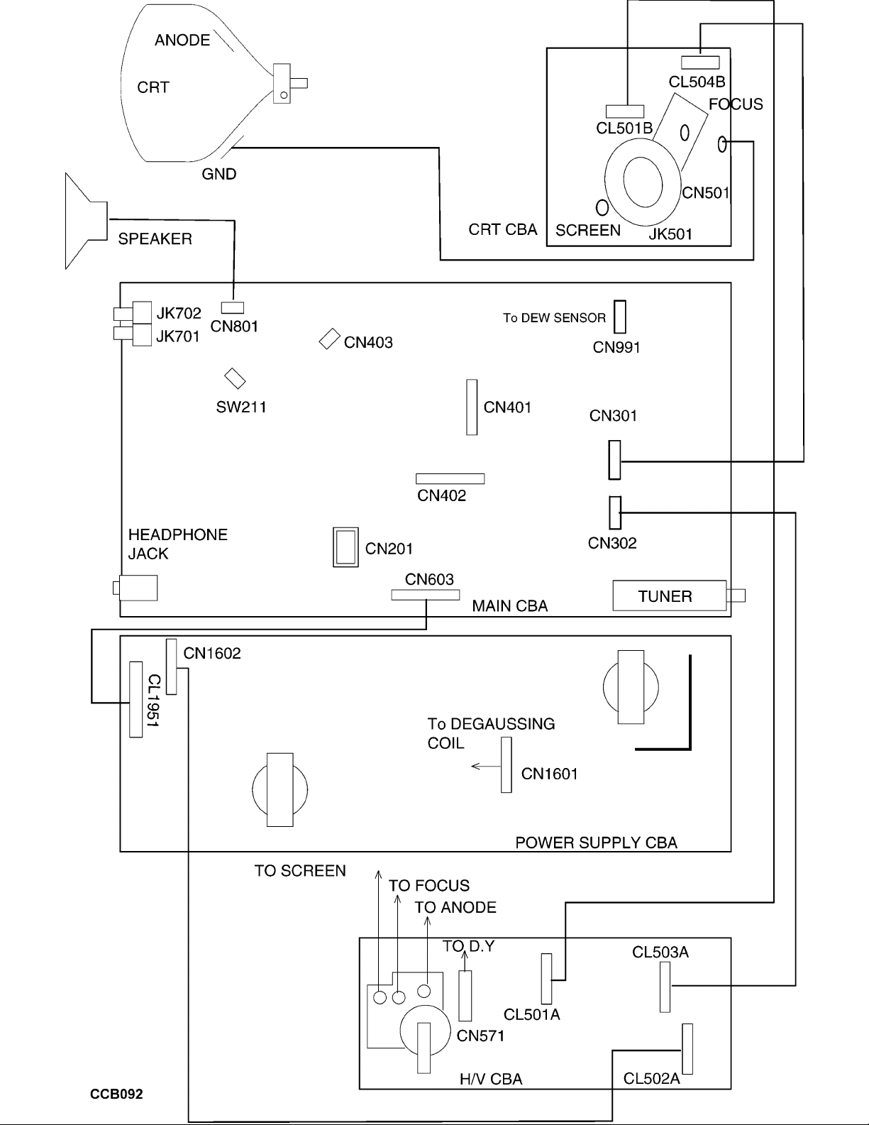
1. WIRING DIAGRAM
2. MAIN 1/4 SCHEMATIC
3. MAIN 2/4 SCHEMATIC
4. MAIN 3/4 SCHEMATIC
5. MAIN 4/4 SCHEMATIC
6. HV/CRT SCHEMATIC
7. MAIN CBA TOP VIEW
8. MAIN CBA BOTTOM VIEW
9. HV CBA TOP VIEW
10. HV CBA BOTTOM VIEW
11. CRT CBA TOP & BOTTOM VIEW
12. JUNCTION CBA TOP & BOTTOM VIEW

Philips Consumer Electronics
Technical Service Data
Service and Quality
Service Publications Dept.
One Philips Drive
P.O. Box 14810
Knoxville, TN 37914
REFER TO SAFETY GUIDELINES
SAFETY NOTICE:
ANY PERSON ATTEMPTING TO SERVICE THIS CHASSIS MUST FAMILIARIZE
HIMSELF WITH THE CHASSIS AND BE AWARE OF THE NECESSARY SAFETY PRECAUTIONS
TO BE USED WHEN SERVICING ELECTRONIC EQUIPMENT CONTAINING HIGH VOLTAGES.
CAUTION: USE A SEPARATE ISOLATION TRANSFORMER FOR THIS UNIT WHEN SERVICING
© Philips Electronics North America Corporation
Visit our World Wide Web Site at http://www.forceonline.com
Manual 5871
Model no.: CCB130AT01
First Publish: 4-25-2000
Rev. Date: 9-27-2000
Print Date: 3/16/05
Safety Notes
GENE R AL SAFETY NOT ES
I MPOR T ANT SAFETY NOT I CE
Proper service and r epai r is important to the s af e, reliable oper ati on of all Philips Consumer Electronics
Company** equipment. T he s er vi ce pr ocedur es recommended by Philips and des cr i bed i n thi s service
manual are effective methods of perfor ming s er vi ce oper at i ons . Some of these s er vi ce oper ati ons require
the us e of tool s specially des igned f or the pur pos e. T he s pecial tools should be us ed wh en and as
recommended.
I t is important to note t hat this manual contains various
CAUT I ONS
and
NOT I CES
which should be
carefully r ead i n order to mini mi ze t he r i s k of personal injury to s er vi ce per s onnel . The possibility ex is ts
that improper service met hods may damage the equi pment . I t also i s important to under s t and t h at these
CAUT I ONS
and
NOT I CES ARE NOT EXHAUSTIVE
. Philips could not possibly know, evaluate and
advise t he s er vi ce tr ade of all conceivable ways in which s er vi ce mi ght be done or of the possible
hazardous consequences of each way. Consequently, Philips has not undertaken any such broad
evaluation. Accor di n gl y , a s er vi cer who us es a s er v i ce procedur e or tool which is not recommended by
Philips must first satisfy himself thoroughly that neither his safety nor the s af e oper ati on of the equi pment
will be j eopar di z ed by the s er vi ce method s el ect ed.
** Hereafter throughout this manual, Philips Consumer Electronics Company will be r ef erred to as
Philips.
WARNING
Cr itical components having s peci al safety char acteris tics are i dent i f i ed wi t h a
or
" S"
by the R ef . No.
in the par ts list and encl os ed wi t hi n a br ok en line* (where s ever al critical components are gr ouped i n one
area) along wi th the s af et y symbol
on the s chemat i cs or exploded vi ews . Use of substitute
replacement parts which do not have the s ame s pecif i ed s afet y character is tics may cr eate s hock, fire, or
other hazards. Under no ci r cums t ances should t h e or i gi nal design be modi fi ed or altered wi t h out written
permission fr om Philips. Philips assumes no l i ability, express or implied, arising out of any unauthoriz ed
modification of design. Servicer assumes all liability.
•
Broken Li ne
____ _ ____ _ ____ _ ____
SAFETY CHECKS
After the or i gi nal service pr obl em has been corrected, a compl et e s af et y check should be made. Be s ur e
to check over the ent i r e s et, not just the ar eas where you have wor k ed. Some pr evi ous servicer may
have l eft an uns afe condit ion, which could be unknowi ngl y passed on to Your customer. Be s ur e to check
all of the f ollowing:
FIRE AND SHOCK HAZARD
IMPLOSION
X-RADIATION
LEAKAGE CURRENT COLD CHECK
LEAKAGE CURRENT HOT CHECK
PICTURE TUBE REPLACEMENT

PARTS REPLACEMENT
FI R E AND SHOCK HAZARD
1. Be s ur e all components are pos i t i oned i n s uch a way as to avoi d t he possibility of adj acent component
shorts. T his is especially important on thos e chassis which ar e t r ans por ted t o and f r om t he s er vi ce s hop.
2. Never release a r epai r ed uni t unless all protective devi ces such as insulators, barriers, covers, strain
reliefs, and other hardware have been i nstalled i n accor dan ce wi th the or i gi nal design.
3. Soldering and wi r i ng mus t be i ns pected t o l ocate possible col d s ol der joints, solder splashes, sharp
solder points, frayed l eads , pinched l eads , or damaged i ns u l at i on (incl uding the ac cor d) . Be cer t ai n to
remove loos e s ol der balls and al l other loos e f or ei gn part i cl es .
4. Check across-the-line component s and other components for physical evidence of damage or
deter ior ation and r epl ace i f necessary. Follow or iginal layout, lead l engt h, and dr es s .
5. No l ead or component should t ouch a r ecei vi ng t ube or a r es i s t or rated at 1 watt or more. Lead
tension around pr ot r udi ng met al surfaces or edges must be avoi ded.
6. Critical components having s pecial safety char acteri s tics are i denti fi ed wi th an
'S '
by the R ef . No. in
the par t s list and encl os ed wi t hi n a br ok en line* (where s ever al critical components are gr ouped i n one
area) along wi th the s af et y symbol
on the s chemat i c d i agr am s and / or exploded vi ews .
7. When s ervici ng any unit, always use a s epar ate i s ol ati on tr ansformer for the chas s i s . Failure t o us e a
separate i s olati on tr ans former may expose you to pos s i ble s hock hazar d, and may caus e damage to
servicing ins t r uments .
8. Many electronic pr odu ct s use a pol ar i z ed ac line cor d ( one wi de pi n on the pl ug) . Defeating t hi s
safety featur e may create a pot en t i al hazard t o t he s er vi cer and t he u s er . Extension cor ds which do not
incorporate t h e pol ar i z i ng f eatu r e s houl d never be us ed.
9. After reassembly of the uni t, always perform an
ac leakage test
or resistance tes t from the l i ne cor d t o
all exposed met al parts of the cabi net . Also, check all metal control shafts (with knobs removed),
antenna t er mi n al s , handles, screws, etc., to be s ur e t he uni t may be s af el y operated wi t h out danger of
electrical shock.
* Broken line ____ _ ____ _ ____ _ ____
IMPLOSION
1. All picture tubes used i n current model receivers are equi pped wi t h an i ntegral implosion s ys tem.
Care s houl d always be us ed, and s afet y glass es worn, whenever handling any picture t ube. Avoid
scratching or otherwise damagi ng t he pi ct ur e t ube dur i ng i ns tallation.
2. Use onl y r eplacement tubes specified by the manuf actur er .
X-RADIATION

1. Be s ur e pr ocedur es and ins t r ucti on s to all your service per s onnel cover the s ubj ect of X-radiation.
Potential sources of X-r ays in T V r ecei ver s are t he pi ctur e tube and t he hi gh voltage cir cui ts . T he basi c
precaution which mus t be ex er ci s ed i s to keep t he hi gh voltage at the factor y r ecommended l evel .
2. To avoi d possible expos ur e t o X- r adi ati on and elect r ical shock, only the manuf actur er ' s specified
anode connector s must be us ed.
3. It is essential that the s er vi ce technician has an accu r at e H V meter available at all times. T he
calibration of this meter should be checked per i odi cally against a r ef er ence s t andar d.
4. When the H V ci r cui t r y is operating pr oper l y ther e i s no possibility of an X-radi ation pr obl em. High
voltage s houl d al ways be k ept at the manufactur er ' s rated val ue - no hi gher - for optimum perfor mance.
Every time a col or set is serviced, the br i ght ness should be r un up and down while moni tor i ng t he H V
with a met er to be cer t ai n that the HV i s regulated correctly and does not exceed t he s peci fi ed val ue. We
sugges t that you and you r technici ans review tes t procedures so t hat HV and HV r egul ati on ar e al ways
checked as a s t andar d s er vi ci ng pr ocedur e, and the r eas on for this prudent routine i s clearly unders tood
by ever yone. It is important to us e an accu r at e and r eliable HV meter . I t is recommended t h at the HV
reading be r ecor ded on each customer's invoice, which will demonstrate a pr oper concern for the
customer's safety.
5. When tr oubleshoot i ng and mak i ng t es t measurements in a r ecei v er with a pr obl em of excessive hi gh
voltage, reduce the l i ne vol t age by means of a Var i ac t o br i ng t he HV i nt o accept abl e limits while
troubleshooti ng. Do not operate t he chassis longer than necessary to l ocate t he caus e of the excessive
HV.
6. New pictur e tubes are s peci f i cally designed to wi t hs t and hi gher operating vol tages without creating
undesirable X- r adi at i on . I t is strongly recommended that any shop t es t fixture whi ch is to be us ed wi t h
the new hi gher voltage chassis be equi pped wi t h one of the new type tubes designed f or this service.
Addi t i on of a per manent l y connected HV meter to the s hop t es t fixture i s advisable. T he CR T types used
in these n ew s ets should never be r epl aced wi t h any other types, as this may result in excessive
X-radiation.
7. It is essential to us e t he s pecifi ed pi ctur e t ube t o avoi d a possible X- r adiati on problem.
8. Most T V r ecei ver s contain some ty pe of emer gency " Hold Down" circuit to pr event HV fr om r is i ng t o
excessive l evel s in the pr es ence of a failure mode. T hese var i ous circuits should be under s t ood by all
technicians servicing t hem, especially since many hold down cir cuits are inoper at i ve as long as the
receiver performs normally.
L EAKAGE CURRENT COLD CHECK
1. Unplug t he ac line cor d and connect a j u mper between t he t wo pr ongs of the plug.
2. Turn on the power switch.
3. Measure the r es i s t ance val u e bet ween the j umper ed ac pl ug and all exposed cabi n et parts of the
receiver, such as screw heads, antennas, and cont r ol shafts. When t he ex pos ed met allic par t has a
return path to t he chassis, the r eadi ng s houl d be bet ween 1 megohm and 5. 2 megohms. When the
exposed met al does not have a r et ur n path to t he chassis, the r eadi ng mu s t be i nfi ni ty. Remove t h e
jumper from t he ac line cor d.

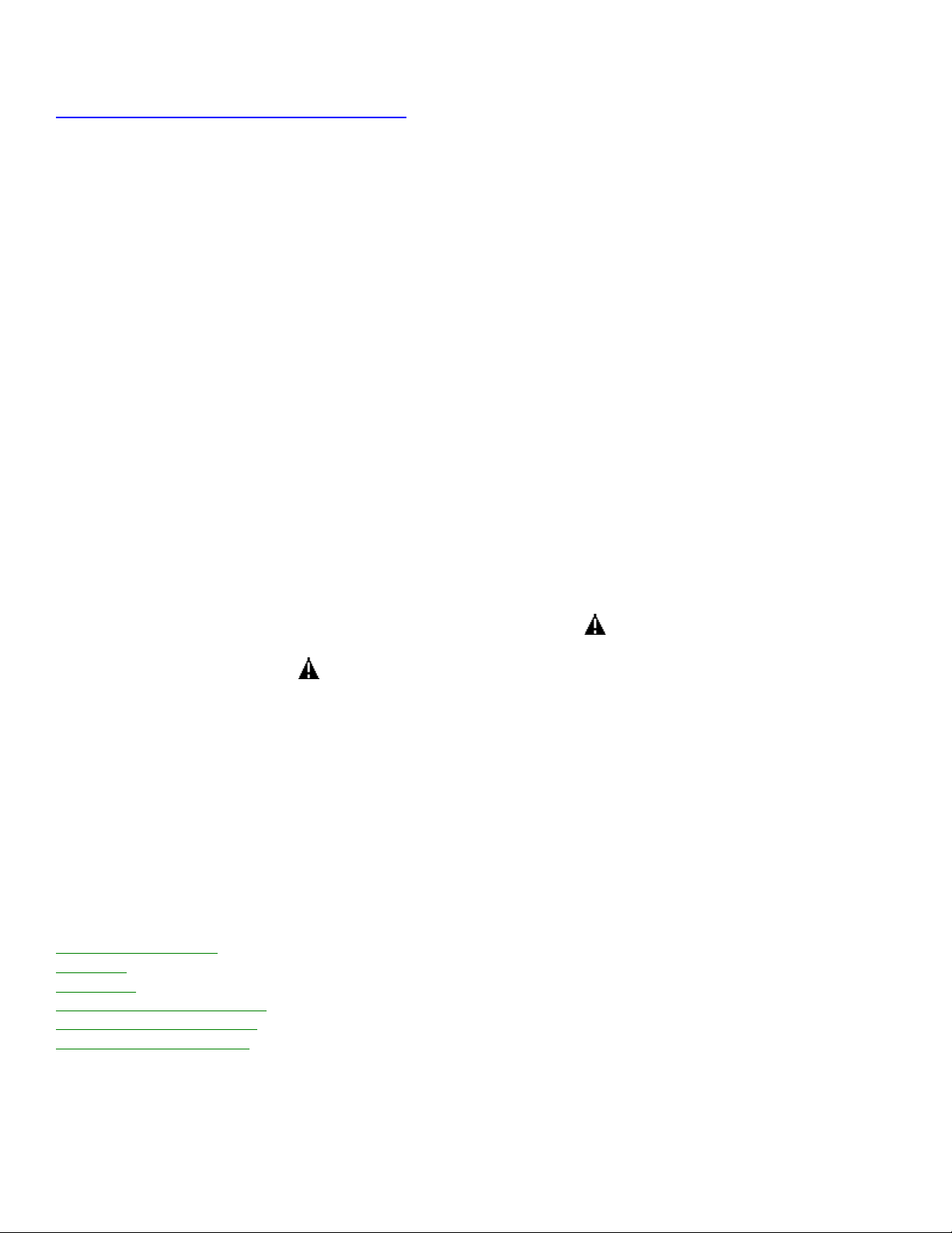
L EAKAGE CURRENT HOT CHECK
1. Do not use an is olation tr ansformer for this test. Plug the completel y reassembled r eceiver directly
into the ac ou t l et .
2. Connect a
1.5 k, 1OW resistor
paralleled by a
0.15uF. capacit or
between each exposed
metallic cabi net part and a
good ear t h ground
such as a wat er pipe, as shown bel ow.
3. Use an ac v ol t met er with at least 5000 ohms/volt sensitivity to meas ur e t he pot ent i al across the
resistor.
4.
T he potenti al at any point should not exceed 0 . 75 volts
.
A l eak age current tester may be
used t o make t h i s test; leakage current must not exceed 0 . 5 mi lliamp. I f a meas u r ement is outside of the
specified limits, there i s a possibility of shock hazard. The r ecei ver should be r epair ed and r echecked
before r etur ni ng i t to the cus t omer .
5
. Repeat the above pr ocedur e w i t h the ac pl u g r ever sed.
(Note: An ac adapt e r is
necessary when a pol ar i z ed pl ug i s used. Do not defeat the polar i z i n g f eat u r e of the pl ug. )
OR
With the i ns t r ument completely reass embled, plug the AC line cor d di r ectl y into a 120V AC ou t l et .
(Do
not use an isolation transformer during t hi s test.)
Use a l eak age current tester or a
metering s ys t em t hat complies with Amer ican Nati onal Standards Institute ( ANS I ) C101.1 Leakage
Current for Appliances and U nder wr i t er s Laboratories (UL) 1410, (50.7).
W it h the in st r umen t
AC s w i t ch first in the on position and t hen in the off position, measur e f r om a
known earth ground (met al water pipe, conduit , etc.) to all exposed met al
par t s of the in st r ument (antennas, handle br acket s, metal cabinet, screw
heads, metallic ov er l ay s , control shafts, etc.), especially any exposed met al
par t s that offer an electrical return path to t he chassis.
Any current
measur ed must not exceed 0.5 milliamp.
R everse t he i ns t r umen t power cord
plug in the out let and repeat the t est . See gr aphi c bel ow .
PICTURE TUBE REPLACEMENT
T he pr i mar y source of X-radiation in this television r eceiver is the pi ct ur e t ube. The pi ctu r e t ube ut ilized
in this chassis is specially constr ucted to l i mi t X-radiation emissions. For continued X - r adi ati on protecti on,
the r epl acement tube mus t be t he s ame t ype as the or i gi nal, including s u ffix letter, or a Philips approved
type.
PARTS REPLACEMENT
Many electrical and mechani cal parts in Philips television s ets have s peci al safety r elated char acter i s t i cs .
T hese char act er i s ti cs are oft en not evident from vis ual inspection nor can the pr otecti on afforded by them
necessarily be obt ai ned by using r epl acement components rated f or higher voltage, wattage, etc. The
use of a s u bs t i t ut e par t which does not have the s ame s afet y char acteri s tics as the Philips recommended
replacement part shown in thi s service manual may cr eate s hock, fire, or other hazards
TV SAFETY NOTES
SAFETY CHECKS
IMPLOSION

X-RADIATION
PICTURE TUBE REPLACEMENT
PARTS REPLACEMENT
W AR NI NG
Before r emovi ng t h e CRT anode cap, turn the uni t
OFF
and s hor t the
HI GH VOLT AGE
to the
CR T DAG
ground.
S E R VI CE NOT E:
T he CR T DAG
is not at chassis ground.
TV-VCR COMBI SAFETY NOTES
I MPOR T ANT SAFETY PRECAUT I ONS
Prior to s hi pment from the f actor y , our products are s t r i ctl y inspected f or recognized pr oduct safety and
electrical codes of the count r i es in which they ar e to be s ol d. However, in order to maint ain such
compliance, it is equally important to i mpl ement the f ollowing pr ecaut i ons when a s et is being s er vi ced.
SAFETY PRECAUTIONS FOR TV CIRCUITS
1. Before r et ur ni ng an i ns tr ument to t he cus tomer , always make a s af et y check of the ent i r e i ns t r ument ,
including, but not limited t o, the f ollowing i tems :
a. Be s ur e t hat no built-in protecti ve devi ces are defecti ve or have been defeated dur i n g s er vi cing. (1)
Protective s hi el ds are pr ovi ded on this chassis to pr otect both the t echni ci an and t he cus t omer .
Correctly replace al l missing pr ot ect ive s hi el ds , including any removed for servicing conveni ence. (2)
When reinstalling the chassis and/or other assembly in the cabinet , be s ur e t o put back in place all
protective devi ces , including but not limited to, nonmetallic con t r ol knobs, insulating f i s h paper s ,
adj ustment and compar tment covers/shields, and i s ol ati on r es i stor/capacitor networks. Do not
operate t hi s instrument or permit it to be oper ated wi t hout al l protective devi ces correctly installed and
functioning. Servicers who defeat safety features or fail to perf or m s afety checks may be liable f or any
resulting damage.
b. Be s ur e t hat there ar e no cabi net openings through which an adult or child mi gh t be abl e t o i ns er t
their fingers and con t act a haz ar dous voltage. Such openings include, but are not limited t o, (1)
spacing between the pi ctur e t u be and t h e cabinet mask, (2) excessively wide cabi net ventilation slots ,
and (3 ) an impr operly fitted and/or incorrectly secured cabi net back cover .
c. Do a
LEAKAGE CURRENT CHECK
ANY MEASUREMENT S NOT WITHIN T HE LI MI TS SPECIFIED HE R EI N I NDI CAT E A POT E NT I AL SHOCK
HAZARD T HAT MUST BE ELIMI NAT ED BE F OR E RETURNI NG T H E I NSTRUMENT TO T H E CUST OMER OR
BEFORE CONNE CT I NG T H E ANTENNA OR ACCE SSORIES.

d. X-R adiation and Hi gh Voltage L i mi t s
- Because the pi ctur e t ube i s the pr i mar y potential source
of X-radiation in s olid-state T V receiver s , it is specially constructed to pr ohi bit X-radiation emissions.
For continued X - r adi ati on protecti on, the r epl acement picture t u be mus t be t he s ame t ype as the
original. Also, because t he pi ctur e tube s hi el ds and mount i n g har dwar e per f or m an X-r adiati on
protection function, they must be correctly in place. High voltage mus t be meas ur ed each ti me
servicing is performed t hat involves B+, horizontal deflection or high voltage. Correct operation of the
X-radiation protecti on cir cuits also mus t be r econf i r med each time they ar e s er vi ced. (X-radiation
protection circuits also may be cal l ed " hor iz ont al disable" or "hold down. " ) Read and appl y the hi gh
voltage limits and, if the ch as s i s is so equi pped, the X- r adiat i on protecti on cir cuit specifications given
on i nstrument labels and i n the
Pr oduct Safety & X-Radiation
Warning note on the s er vi ce data
chassis schematic. High voltage is maintained wi t hi n s pecifi ed l i mi t s by close tol er ance s afet y- r el ated
components/adjustments in the hi gh- vol tage ci r cui t. I f high voltage ex ceeds specified limits, check
each component specified on the chassis schematic an d t ake corrective act i on.
2. Read and compl y with all caution and s af et y- r el at ed not es on or inside the r eceiver cabinet, on the
receiver chassis, or on the pi ctur e tube.
3. Desi gn Alteration Warning
- Do not alter or add to t he mechani cal or electrical design of this TV
receiver. Design alterati ons and addi t i on s , including, but not limited t o ci r cui t modifications and th e
addi t i on of items such as auxiliary audio and/or video out put connections, might alter the s af et y
character istics of this receiver and cr eate a haz ar d to the us er . Any desi gn alterations or additions will
void t he manuf act ur er ' s warranty and may make you, the s er vi cer , responsible f or personal injury or
property damage r es ul t i ng t her efr om.
4. Pict ur e T ube I mpl os ion Protection Warning
- The pictur e tube i n thi s receiver employs integral
implosion protecti on. For continued i mpl os i on protection, replace t he pi ctu r e tube onl y with one of the
same t y pe number . Do not remove, install, or otherwise handl e t he pictur e t ube i n any manner without
first putting on shatterproof goggles equipped wi t h side s hi el ds . People not so equi pped mus t be kept
safely away while pictur e t ubes are handl ed. Keep the pi ct ur e t ube away fr om your body. Do not handle
the pictur e t ube by its neck. Some " i n- line" picture t ubes are equi pped wi t h a per man ent l y attached
deflection yoke; because of potential hazard, do not try to r emove s uch "per manently attached" yokes
from the pi ctur e t u be.
5. Hot Chassis Warning
a. Some T V r eceiver chassis are el ectr i cally connected di r ect l y to one conductor of the ac pow e r cord
and may be s er vi ced s afel y without an is olation tr ans f or mer only if the ac po w er plug i s inserted s o
that the chass i s is connected t o t he gr ou nd s i de of the ac pow er source. T o conf i r m that the ac
power plug i s inserted correctly, with an ac vol t met er , measure bet ween the chassis and a k nown
ear th ground. I f a vol t age r eading i n excess of 1.OV i s obtained, remove and r ei ns er t the ac pow e r
plug in the oppos i t e pol ar i t y and agai n measur e t he vol t age pot ent i al between the chassis and a
known ear th ground.
b. Some T V recei ver chassis normally have 85Vac ( R MS ) between chassis and ear th ground
regardless of the ac pl ug pol ar i t y. T his chassis can be s af ety- s er vi ced onl y with an is olation
transformer inserted i n the power line between the r ecei ver and t he ac po wer source, for both
personnel and tes t equipment protection. Some T V r ecei ver chassis have a s econdar y gr ound s ys t em
in addi ti on to the mai n chassis ground. T his secondary ground s y s t em i s not isolated f r om the ac
power line. T he two gr ound s y s t ems are el ectr i cal l y separated by ins ulation materi al that must not
be def eated or altered.
6. Observe or i gi nal lead dr ess. T ake ext r a car e to assure correct lead dr ess in the f oll owi ng ar eas :
a.
near sharp edges ,
b. near thermally hot parts - be s ur e t hat leads and compon ent s do not touch

thermally hot parts,
c. the ac s uppl y ,
d. high voltage, and
e. antenna wi r i ng. Always inspect in all areas
for pinched, out of place, or frayed wi r i ng. Check ac pow e r cord for damage.
7. Components, parts, and/or wiring t hat appear to have over heated or are ot h er wi s e damaged s houl d be
replaced wi t h components , parts, or wiring t h at meet original specifications. Additionally, determine th e
cause of overheating and/or damage and, if necessary, take corrective act i on to r emove any potential
safety hazard.
PRECAUTIONS DURING SERVICE
A. Parts identified by the
symbol are cr i t i cal for safety. Replace onl y with par t number specified.
B. I n addi tion to s af et y, other parts and assemblies are s peci f i ed f or conformance wi t h regulations
appl y i ng t o s pur i ous radiation. These mus t also be r epl aced onl y with s pecifi ed r epl acement s .
Examples:
RF converters, RF cables, noise bl ocki ng capaci tor s , and noi s e bl ocki ng f ilters, etc.
C. Use s peci f i ed i nt er nal wiring. Note es peci al l y:
1) Wires covered wi t h PVC t u bi ng
2) Double i ns u l ated wi r es
3) High voltage leads
D. Use s pecif i ed i n s ul ati ng mat er i al s for hazardous
live par ts . Note es pecially:
1) Insulation T ape
2) PVC t u bi ng
3) Spacers
4) Insulators for transistors
E. When r epl acing ac pr i m ar y side component s (transformers, power cord, etc.), wrap ends of wires
securely about the ter mi nals before s ol der i ng.
F. Observe that the wi r es do not contact heat producing par t s (heatsinks, oxide met al film r es i s tor s ,
fusible r es i s t or s , etc.)
G. Check that replaced wi r es do not contact sharp edged or pointed par t s .
H. When a power cord has been r eplaced, check that 10-15 kg of force i n any dir ecti on will not
loos en it.
I . Also check areas surrounding r epai r ed l ocat i ons .
J. Use care t hat foreign obj ects (screws, solder droplets, etc.) do n ot remain ins i de the s et .
K. Crimp t ype w ir e connector
When replaci ng the power transformer in s ets where the connecti ons between the power cord and power
transformer primary lead wi r es are per f or med us ing cr imp t y pe connectors , in order to pr event shock
hazards, perform car efully and pr eci s el y the following s t eps .
R eplacement procedure
1) Remove the ol d connector by cutting the wi r es at a poi n t clos e t o the connector.
I mport ant :
Do
not re-use a connect or (discard i t ) .
2) Strip about 15 mm of the ins ul ati on fr om the ends of the wi r es . I f the wi r es are s t r anded, twist
the st r ands to avoi d f r ayed conductor s .
3) Align the l engt hs of the wi r es to be connected. Insert the wi r es fully into t he connector .
4) Use t he cr i mpi ng t ool to cr i mp t he met al sleeve at the cent er position. Be s ur e t o cr i mp f u lly to
the compl ete clos ur e of the tool .
L. When connecti ng or disconnecti ng the VCR connectors , first, disconnect the ac pl u g f r om the ac s u ppl y
socket.
SAFETY CHECK AFTER SERVICING
Examine the ar ea s urrounding t he r epai r ed l ocati on for damage or deterioration. Observe t h at screws,
parts and wi r es have been r eturned to or i gi nal positions. Afterwards, perform t he f ollowing t es ts and
confirm the s peci fi ed val ues in or der to ver i fy compliance wi t h safety standar ds.
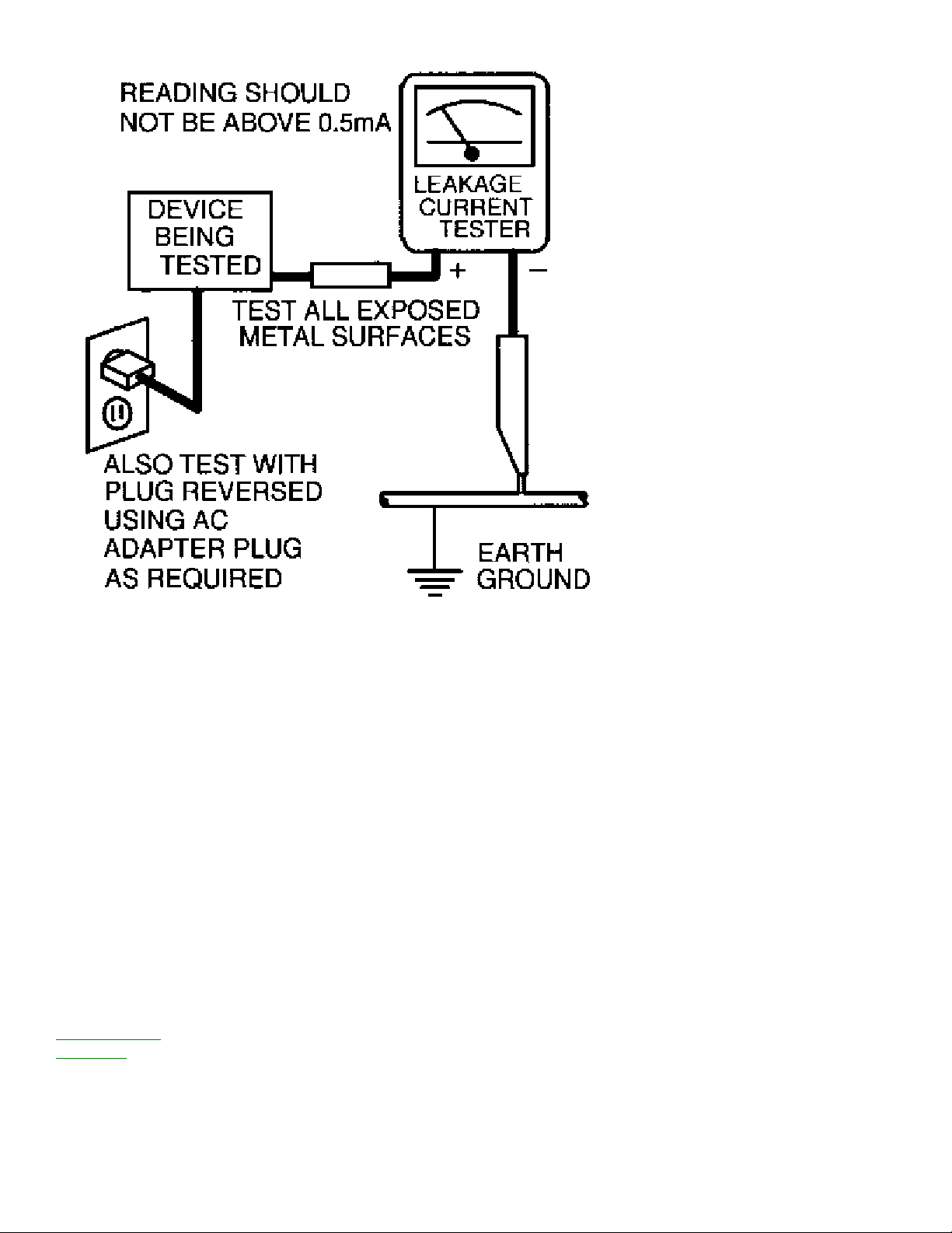
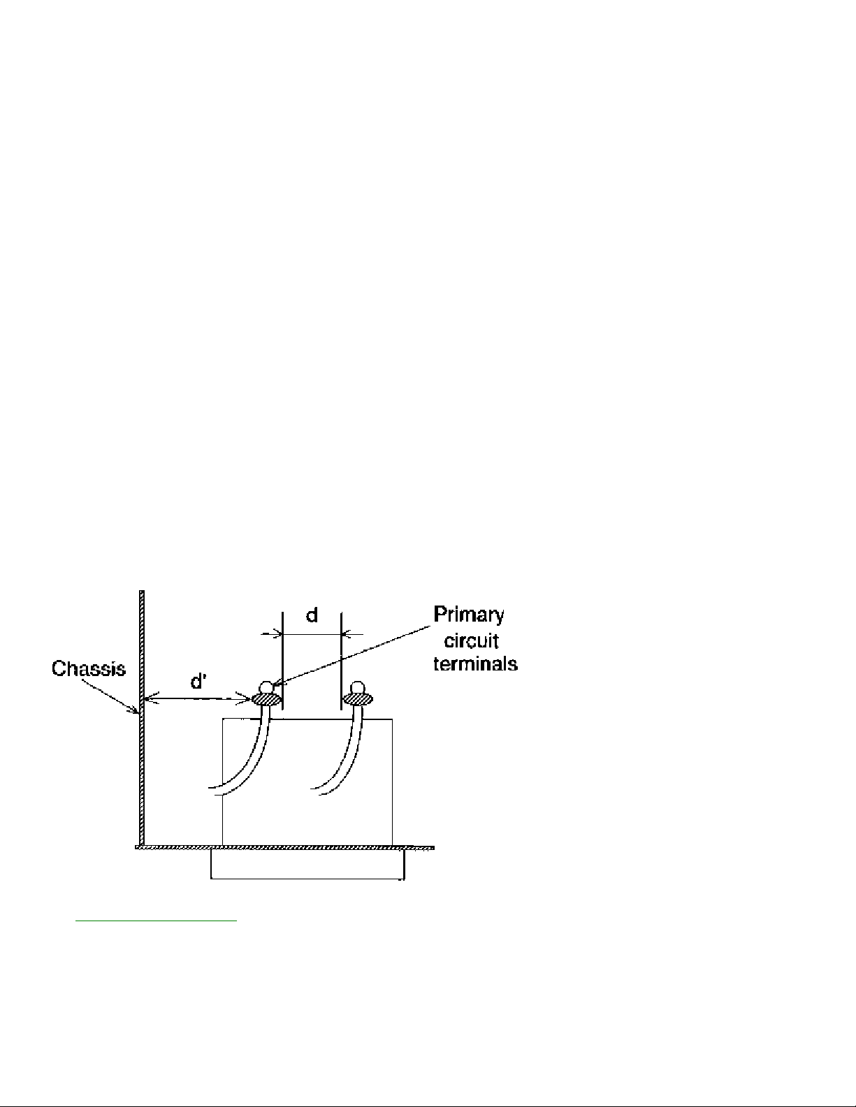
1. Clearance D i st ance
When replaci ng pr i mar y circuit components, confirm s peci fi ed cl ear ance di s t ance ( d) and ( d' ) between
solder ed t er mi n al s , and between terminals and s urrounding met al lic par t s . (See gr aphi c bllow)
T able 1 : Ratings for selected ar ea
AC L i n e Volt age R egion Clear ance Distance
(d) (d')
USA or > 3.2 mm
110 to 130 V CANADA (0.126 inches)
Note
: This table is unofficial and f or reference onl y. Be s ur e t o conf i r m the pr eci s e v al ues .
2.
LEAKAGE CURRENT CHECKS

VCR SAFETY NOTES
FIRE & SHOCK HAZARD (VCR)
1. Be s ur e that all components are pos i ti oned i n such a way to avoi d possibility of shorts to adj acent
components. T his is especially i mportant on those chassis which are t r ans por ted t o and f r om the r epai r
shop.
2. Always replace all protective devi ces such as insulators and barriers after working on a s et .
3. Check for damaged i ns u l at i on on wir es including t he ac cor d.
4. Check across-the-line component s for damage and r epl ace if necessar y.
5. After re-assembly of the uni t , always perform an ac l eak age t es t on t he ex pos ed met allic par t s of the
cabinet such as the k nobs , antenna t er mi nal s , etc. to be s ur e t he s et is safe to oper ate wi thout danger of
electrical shock.
Do n ot use a line i s ol at i on transf ormer during this test.
Use an ac v ol t met er
having 5000 ohms per volt or more s ens i t i v i t y in the f ollowing manner: Connect a 1500 ohm 10 wan
resistor, paralleled by 0. 15 MFD ac t y pe capaci tor , between a k now n good ear t h ground ( wat er pipe,
conduit, etc.) and the ex pos ed met allic par t s , one at a ti me. Measure t he ac v ol t age acr oss the
combination 1500 ohm r es i s t or and 0 . 15 MFD capacitor . Reverse t he ac pl ug on the s et and r epeat ac
voltage meas ur ement s again for each expos ed met allic par t . Voltage meas ur ed mu s t not exceed O.6 volts
R.M.S. T his corresponds to 0. 4 milliamp ac. Any value ex ceedi ng t hi s limit cons titutes a pot ent i al shock
hazard and mus t be corrected i mmedi atel y.
GENE R AL
Power Supply-This receiver is designed f or operation on 120 Volts , 6OHz alternating current (ac) only.
Never connect to a s uppl y having a di fferent frequency or voltage.
IMPORTANT NOTICE
T his device empl oys many ci r cuits , components, and mechani cal parts designed f or protection agai ns t
fire, shock and R F interference. For continued s afet y any servici ng s h oul d be per f or med by qualified
personnel and exact replacement parts should be us ed. Under no cir cums t ances should t he or i gi nal
design be al ter ed.
PRODUCT SAFETY GUIDELINES FOR ALL PRODUCTS
CAUT I ON
: Do not modify any ci rcuit. Service wor k should be per f or med on l y after you ar e t hor oughl y
familiar with all of the following s afet y checks . Risk of potential hazards and i nj u r y to the us er increases if
safety checks are not adhered to.
US E A S E P AR AT E I SOLATI ON T RANSFORMER FOR THIS UNI T WHEN SER VI CI NG.

PREVENTION OF ELECTROSTATIC DISCHARGE (ESD)
Some s emi conductor solid s tat e devi ces can be damaged eas i l y by static el ect r i ci t y . Such components
commonl y ar e called E l ectr os t at i cally Sensitive ( E S ) Devices, Examples of typical ES devices are
integrated ci r cui t s and s ome f i el d-ef f ect transis tors and s emi conductor "chip" components. T he following
techniques should be us ed t o hel p r educe the i nci dence of component damage caus ed by electrostatic
dis charge (E S D) .
1. Immediatel y before handl i ng any semiconductor component or semiconductor-equipped assembly,
drain off any ESD on your body by touching a k nown ear th ground. Alternatively, obtain and wear a
commer ci all y available di s char gi ng E S D wr is t strap, which should be r emoved f or potential shock reas ons
prior to appl yi ng power to the uni t under test.
2. After removing an electr ical assembly equipped wi t h E S devices, place the assembly on a con duct i ve
surface s uch as aluminum foil, to pr event electrostatic ch ar ge bui l dup or exposure of the assembly.
3. Use onl y a gr oun ded- t i p s ol der i ng i r on to s ol der or unsolder ES devices.
4. Use onl y an anti -s tatic s ol der removal device. Some s ol der removal devices not classified as "antistatic
(ESD protected)" can generate an electr ical charge s ufficient to damage E S devices.
5. Do not use f r eon· pr opel l ed chemi cal s . T hese can gener ate el ect r i cal charges sufficient to damage ES
devices.
6. Do not remove a r epl acement ES device f r om i t s protective pack age un t il immediatel y before you ar e
ready to ins t all it (Most replacement ES devices are pack aged wi th l eads electrically shorted toget h er by
conductive f oam, aluminum f oil or comparable conducti ve mat er i al) .
7. Immediatel y before r emovi ng t he pr otecti ve mater i al from the l eads of a r epl acemen t ES device, touch
the prot ect i ve mat er i al to the chassis or circuit assembly into whi ch the devi ce will be i ns t alled.
CAUT I ON
: Be s ur e no power is applied to t he chassis or circuit and obs er ve all other safety pr ecautions.
8. Minimize bodily motions when handli ng u n pack aged r epl acement ES devices. (Otherwise har ml ess
motion such as the br us h i ng t ogether of your clothes fabric or the l i f t i ng of your feet fr om a car pet ed
floor can generate s tat i c el ect r i ci t y (ESD) sufficient to damage an ES device.)
NOT E to CAT V s yst em I nst aller:
T his reminder is provided to cal l the CAT V sys tem i ns taller's attention to ar ti cl e 820-22 of the NE C t h at
provides guidelines for proper grounding and, in par ticular , specifies that the cable gr ound s h all be
connected t o t he gr oundi ng s ys t em of the building, as close to t h e poi nt of cable ent r y as practical.

Philips Consumer Electronics
Technical Service Data
Service and Quality
Service Publications Dept.
One Philips Drive
P.O. Box 14810
Knoxville, TN 37914
REFER TO SAFETY GUIDELINES
SAFETY NOTICE:
ANY PERSON ATTEMPTING TO SERVICE THIS CHASSIS MUST FAMILIARIZE
HIMSELF WITH THE CHASSIS AND BE AWARE OF THE NECESSARY SAFETY PRECAUTIONS
TO BE USED WHEN SERVICING ELECTRONIC EQUIPMENT CONTAINING HIGH VOLTAGES.
CAUTION: USE A SEPARATE ISOLATION TRANSFORMER FOR THIS UNIT WHEN SERVICING
© Philips Electronics North America Corporation
Visit our World Wide Web Site at http://www.forceonline.com
Manual 5871
Model no.: CCB130AT01
First Publish: 4-25-2000
Rev. Date: 9-27-2000
Print Date: 3/16/05
Mechanical Adjustments
DISASSEMBLY INSTRUCTIONS
Cabinet and Main Assemblies
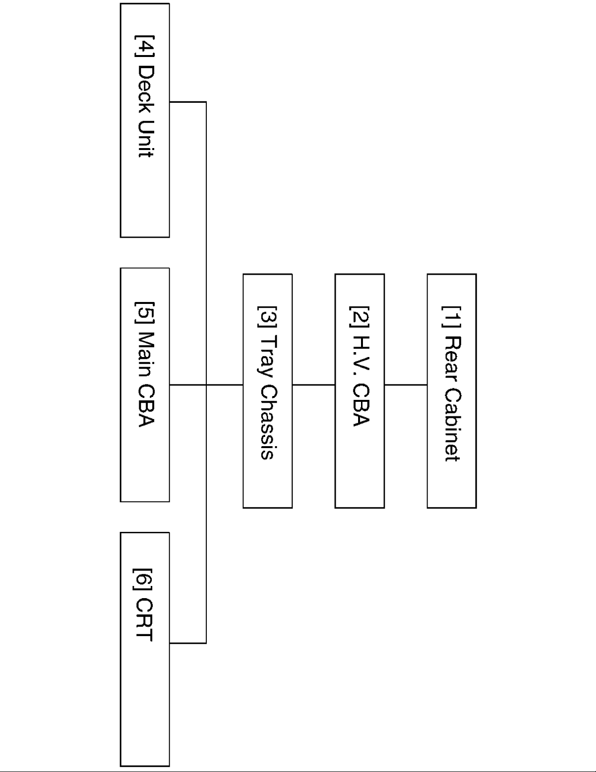
Disassembly Flowchart
This flowchart indicates the disassembly steps for the cabinet parts, and the CBA in
order to gain access to item(s) to be serviced. When reassembling, follow the steps
in reverse order. Bend, route and dress the cables as they were.
Click here for Disassembly Flowchart
Caution !
When removing the CRT, be sure to discharge the Anode Lead of the CRT with the
CRT Ground Wire before removing the Anode Cap.
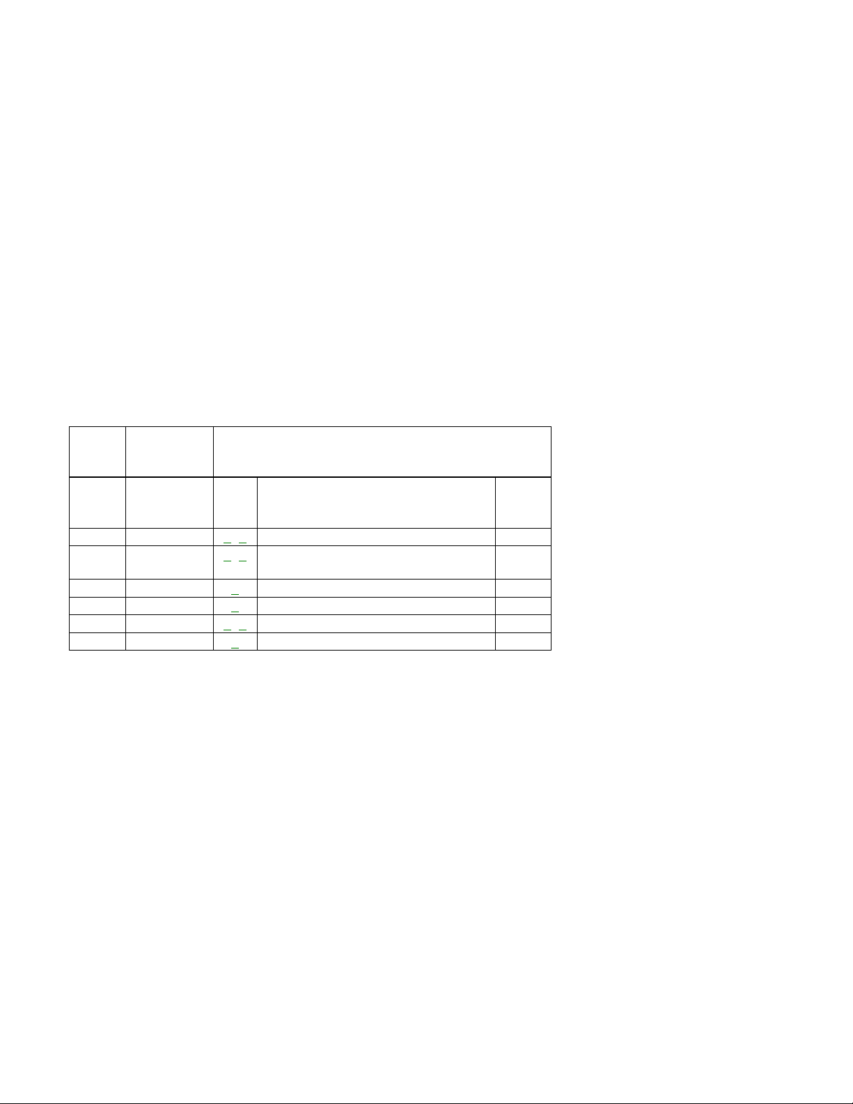
Disassembly Method (CCB132)
STEP/
LOC. NO.
PART
REMOVAL
FIG. NO.
REMOVE/
UNLOCK/RELEASE/
UNPLUG/
UNCLAMP/DESOLDER
NOTE
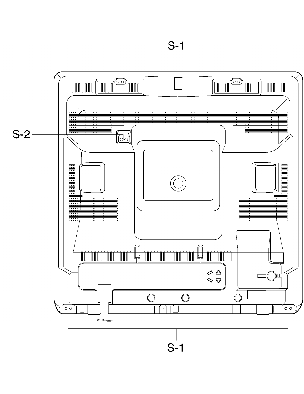
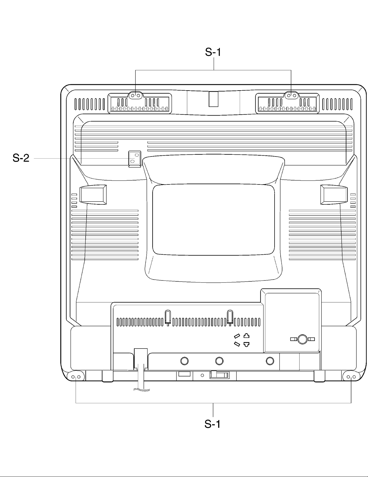
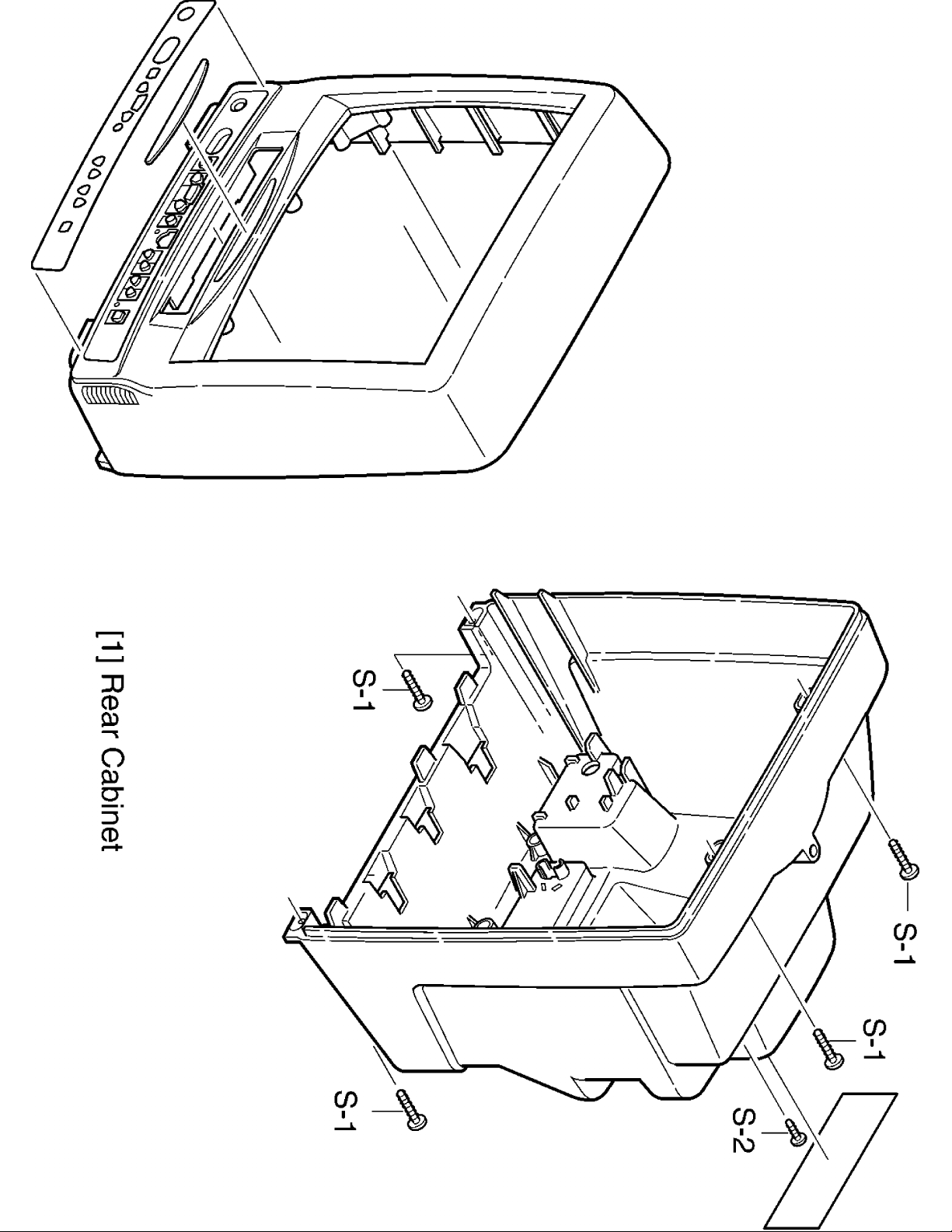
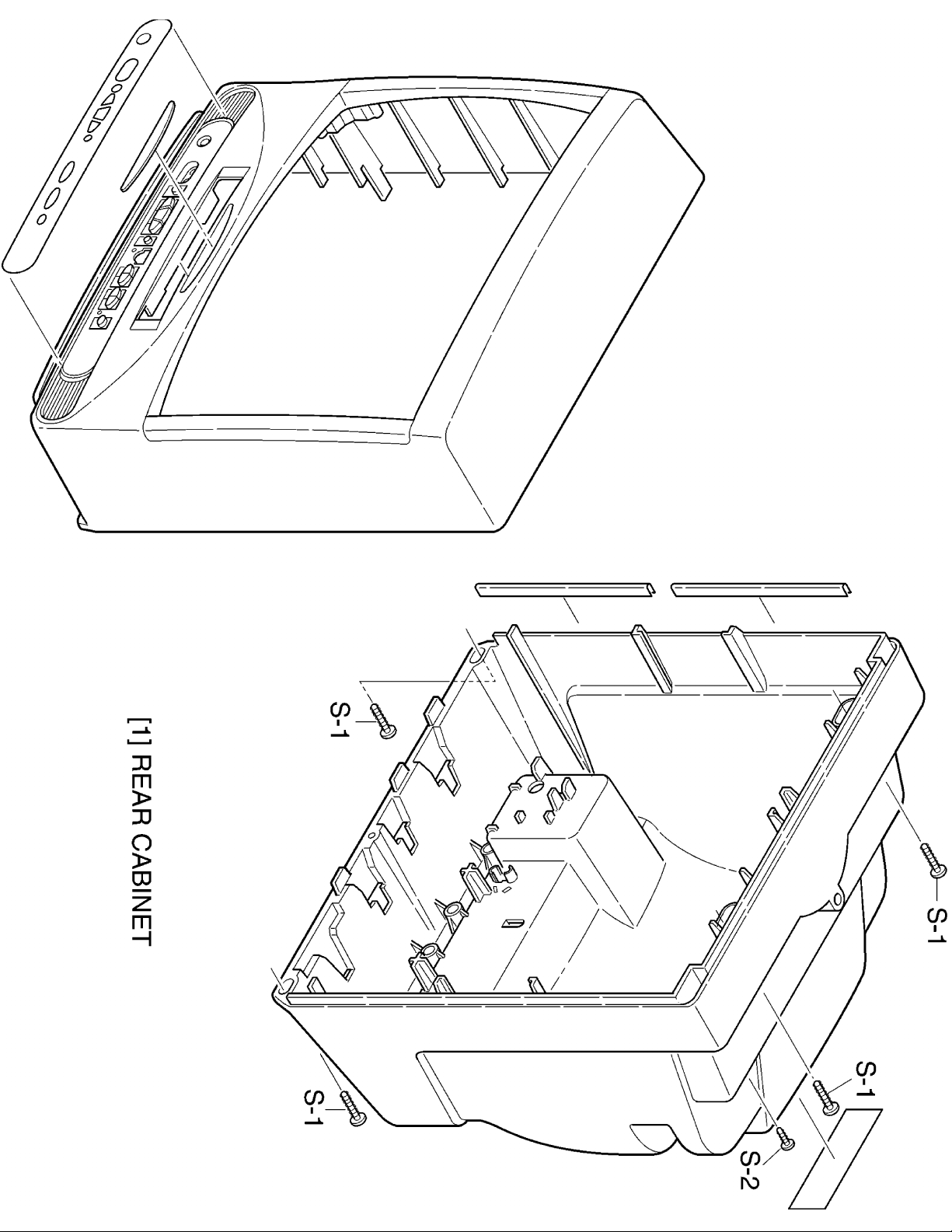
[1]
Rear Cabinet
1
,
2,
3,
4
4(S-1), (S-2)
1
[2]
H/V CBA(With
Holder)
5
,
7
Anode Cap, CRT CBA,
CL501A, CN503, CN571,
CN575, CN602 2(S-3),
2(L-1)
2
[3]
TrayChassis
5
CN601, CN801
3
[4]
Deck Unit
5
7( S-4), 1( S-5)
4
[5]
Main CBA
5
,
7
6(S-6)
5
[6]
CRT
6
4(S-7)
6
[1] [2] [3] [4] [5]
[1]
Order of steps in procedure. When reassembling, follow the steps in reverse
order. These numbers are also used as the identification (location) No. of parts
in figures.
[2]
Parts to be removed or installed.
[3]
Fig No. showing procedure of part location
[4]
Identification of part to be removed, unhooked, unlocked, released, unplugged,
unclamped, or desoldered.
S=Screw, P=Spring, L=Locking Tab, CN=Connector, *=Unhook, Unlock,
Release, Unplug, or Desloder
2(S-2) = two Screws (S-2)
[5]
Refer to the following ”Reference Notes in the Table“
Reference Notes in the Table
1. Removal of the Rear Cabinet.
Remove Screws 4(S-1) and 1(S-2)
Caution!
Discharge the Anode Lead of the CRT with the CRT Ground
Wire before removing the Anode Cap.
2. Removal of the H/V CBA with Holder. Discharge the Anode lead of the CRT with
the CRT Ground Wire before removing the Anode Cap.
Disconnect the following: Anode Cap, CRT CBA, CL501A, CN503, CN571,
CN575, and CN602.
Remove 2(S-3). Unlock 2(L-1). Pull the H/V CBA backward.
3. Removal of the Tray Chassis. Disconnect CN601 and CN801. Pull the Tray
Chassis backward.
4. Removal of the Deck Unit. Remove 7(S-4) and 1(S-5). Lift up the Deck Unit.
5. Removal of the Main CBA. Remove 6(S-6). Lift up the Main CBA.
6. Removal of the CRT. Remove 4(S-7) and pull the CRT backward.
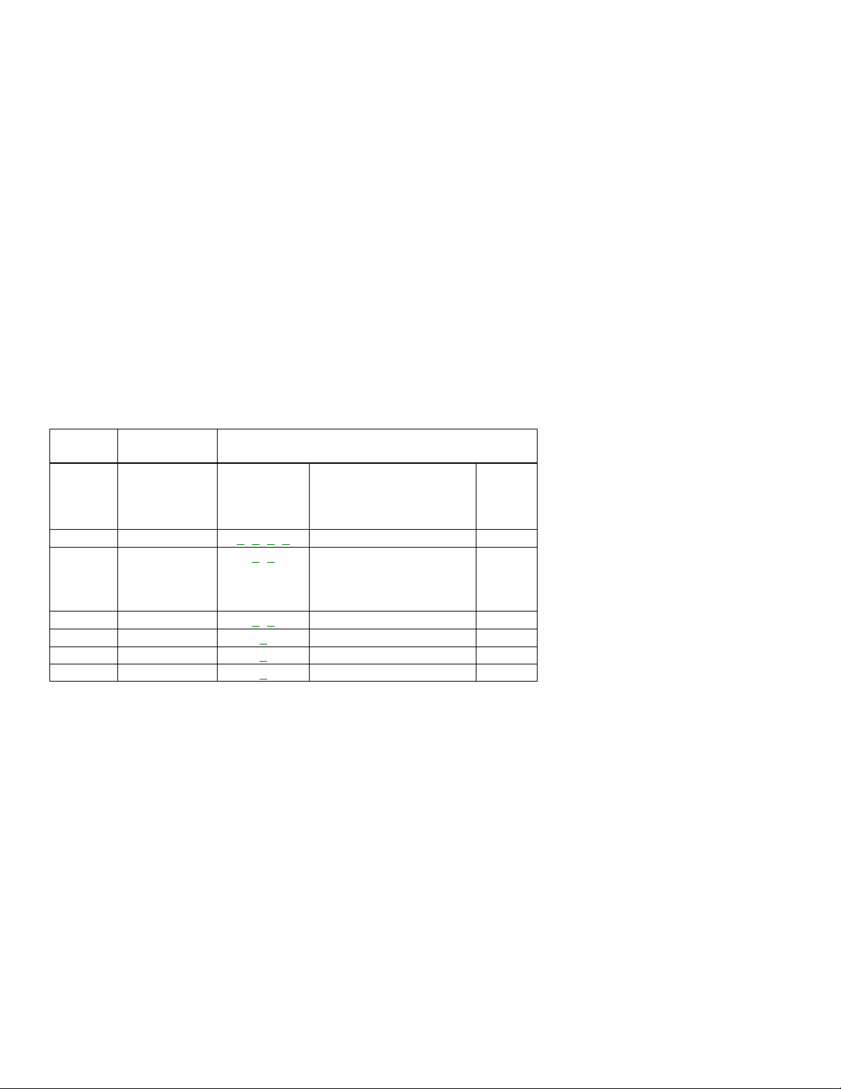
Disassembly Method (CCB255)
STEP/
LOC.
NO.
PART
REMOVAL
FIG.
NO.
REMOVE/*UNLOCK/
RELEASE/UNPLUG/
UNCLAMP/DESOLDER
NOTE
[1]
Rear Cabinet
1
,
2
6(S-1), 1(S-2)
1
[2]
Power Supply
CBA
3
,
5
1(S-3) Anode Cap, CRT CBA, CN301,
CN302, CN571, CN603
2
[3]
Tray Chassis
3
CN801
3
[4]
Deck Unit
3
7(S-4)
4
[5]
Main CBA
3
,
5
3(S-5), 1(S-6)
5
[6]
CRT
4
4(S-7)
6
[1] [2] [3] [4] [5]
[1]
Order of steps in procedure. When reassembling, follow the steps in reverse
order. These numbers are also used as the identification (location) No. of
parts in figures.
[2]
Parts to be removed or installed.
[3]
Fig No. showing procedure of part location
[4]
Identification of part to be removed, unhooked, unlocked, released,
unplugged, unclamped, or desoldered.
S=Screw, P=Spring, L=Locking Tab, CN=Connector, *=Unhook, Unlock,
Release, Unplug, or Desloder
e.g., 2(S-2) = two Screws (S-2)
[5]
Refer to the following ”Reference Notes in the Table“
Reference Notes in the Table
1. Removal of the Rear Cabinet. Remove screws 6(S-1) and 1(S-2).
Caution!
Discharge the Anode Lead of the CRT with the cRT Ground Wire before removing the
Anode Cap.
2. Removal of the Power Supply CBA. Discharge the Anode Lead of the CRT with the
CRT ground wire before removing the Anode Cap.
Disconnect the following: Anode Cap, CRT CBA, CN301, CN302,
CN571, CN603.
Remove 1(S-3).
4. Removal of the Tray chassis. Disconnect CN801, then slide Tray chassis
backward.
5. Removal of the Deck Unit. Remove 7(S-4). Lift up the Deck Unit.
6. Removal of the Main CBA. Remove 3(S-5) and 1(S-6). Pull the Main CBA.
7. Removal of the CRT. Remove 4(S-7) and pull the CRT backward.
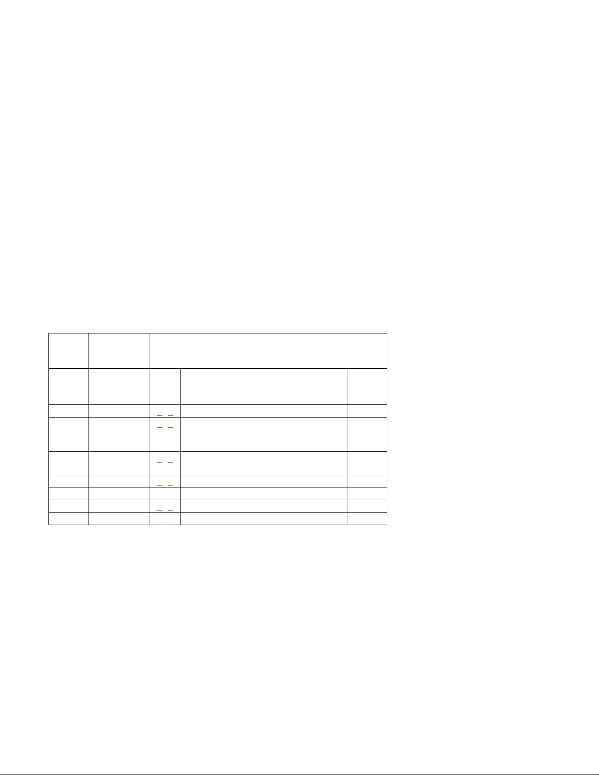
Disassembly Method (VRB130, 190)
STEP/
LOC. NO.
PART
REMOVAL
FIG. NO.
REMOVE/
UNLOCK/RELEASE/
UNPLUG/
UNCLAMP/DESOLDER
NOTE
[1]
Rear Cabinet
1
,
2,
3,
4
4(S-1), (S-2)
1
[2]
H/V CBA(With
Holder)
5
,
7
Anode Cap, CRT CBA,
CL501A, CN503, CN571,
CN575, CN602 2(S-3),
2(L-1)
2
[3]
TrayChassis
3
,
5
CN601, CN801
3
[4]
Deck Unit
3
7( S-4), 1( S-5)
4
[5]
Main CBA
3
6(S-6)
5
[6]
CRT
4
4(S-7)
6
[1] [2] [3] [4] [5]
[1]
Order of steps in procedure. When reassembling, follow the steps in reverse
order. These numbers are also used as the identification (location) No. of
parts in figures.
[2]
Parts to be removed or installed.
[3]
Fig No. showing procedure of part location
[4]
Identification of part to be removed, unhooked, unlocked, released,
unplugged, unclamped, or desoldered.
S=Screw, P=Spring, L=Locking Tab, CN=Connector, *=Unhook, Unlock,
Release, Unplug, or Desloder
2(S-2) = two Screws (S-2)
[5]
Refer to the following ”Reference Notes in the Table“
Reference Notes in the Table
1. Removal of the Rear Cabinet.
Remove Screws 4(S-1) and 1(S-2)
Caution!
Discharge the Anode Lead of the CRT with the CRT Ground
Wire before removing the Anode Cap.
2. Removal of the H/V CBA with Holder. Discharge the Anode lead of the CRT with
the CRT Ground Wire before removing the Anode Cap.
Disconnect the following: Anode Cap, CRT CBA, CL501A, CN503, CN571,
CN575, and CN602.
Remove 2(S-3). Unlock 2(L-1). Pull the H/V CBA backward.
3. Removal of the Tray Chassis. Disconnect CN601 and CN801. Pull the Tray
Chassis backward.
4. Removal of the Deck Unit. Remove 7(S-4) and 1(S-5). Lift up the Deck Unit.
5. Removal of the Main CBA. Remove 6(S-6). Lift up the Main CBA.
6. Removal of the CRT. Remove 4(S-7) and pull the CRT backward.
Disassembly Method (VRB092)
STEP/
LOC.
NO.
PART
REMOVAL
FIG.
NO.
REMOVE/*UNLOCK/
RELEASE/UNPLUG/
UNCLAMP/DESOLDER
NOTE
[1]
Rear Cabinet
1
,
2
4(S-1), 1(S-2), 2(S-3), (S-4)
1
[2]
H/V CBA
3
,
5
Anode Cap, CRT CBA, CL501A,
CN503,CN571,CN575,CN602,
Unclamp H/V CBA
2
[3]
Power Supply
CBA
3
,
5
CN1601,CN603,3(S-6),2(L-1), 4(S-7)
3
[4]
Tray Chassis
3
,
5
CN802
54
[5]
Deck Unit
3
,
5
6(S-8)
5
[6]
Main CBA
3
,
5
4(S-9)
6
[7]
CRT
4
4(S-10)
7
[1] [2] [3] [4] [5]
[1]
Order of steps in procedure. When reassembling, follow the steps in reverse
order. These numbers are also used as the identification (location) No. of
parts in figures.
[2]
Parts to be removed or installed.
[3]
Fig No. showing procedure of part location
[4]
Identification of part to be removed, unhooked, unlocked, released,

unplugged, unclamped, or desoldered.
S=Screw, P=Spring, L=Locking Tab, CN=Connector, *=Unhook, Unlock,
Release, Unplug, or Desloder
2(S-2) = two Screws (S-2)
[5]
Refer to the following ”Reference Notes in the Table“
Reference Notes in the Table
1. Removal of the Rear Cabinet. Remove screws 4(S-1), 1(S-2) and 2(S-3) and
2(S-4).
2. Removal of the H/V CBA. Discharge the Anode Lead of the CRT with the CRT
ground wire before removing the Anode Cap.
Disconnect the following: Anode Cap, CRT CBA, CL501A,
CN503, CN571, CN575, CN602 and unclamp the H/V CBA.
3. Removal of the Power Supply CBA. Disconnect CN1601 and CN603. Slide Power
Supply CBA holder backward. Remove screws 2(S-6). Slide the Power Supply
CBA Holder backward. Remove screws 4(S-7) and release 2(L-1). Pull the Power
Supply CBA backward.
4. Removal of the Tray chassis. Disconnect CN802, then slide Tray chassis
backward.
5. Removal of the Deck Unit. Remove screws 7(S-8). Lift up the Deck Unit.
6. Removal of the Main CBA. Remove screws 4(S-9).
7. Removal of the CRT. Remove screws 4(S10) and pull the CRT backward.
Front Loading Assembly
Before following the procedures described below, be sure to remove Front Loading Assembly
from the main mechanism of the deck assembly. (See
Fig DM3
.) When reassembling, start
with the unit in Cassette-in mode and follow the steps in reverse order.
STEP
/LOC.
No.
START-
ING
No.
PART
REMOVAL
INSTALLATION
Fig. No.
REMOVE/*UNHOOK/
UNLOCK/RELEASE/
UNPLUG/DESOLDER
ADJUSTMENT
CONDITION
[1]
[1]
Guide Holder
T
DM17
2(S-1)
[2]
[1]
Slider Gear
L,R
DM16
,
DM17
*4(L-2)
Eject Position
*[3]
[2]
Slider Shaft
T
DM16
,
DM17
Eject Position
[4]
[4]
Cassette Plate
T
DM17
2(S-2)
[5]
[4]
Slider L
T
DM17
[6]
[4]
Slider R
T
DM17
(S-3)
[7]
[6]
Door Opener A
DM17
[8]
[8]
Lock Lever
DM17
(S-4), *(P-1)
[9]
[3]
Cassette Guide R
DM17
[10]
[3]
Cassette Guide L
R
DM17
[11]
[11]
Joint Holder A
L
DM17
(S-5), *(P-2)
[12]
[11]
Cassette Drive Sub
Gear
R
DM17
, DM18
Eject Position
[13]
[11]
Cassette Drive
R
DM17
, DM18
Eject Position

[13]
[11]
Cassette Drive
Gear
R
DM17
, DM18
Eject Position
[14]
[13]
Cassette Drive
Lever
R
DM17
Cassette Drive Spring
Eject Position
[15]
[14]
Front Door Opener
DM17
, DM18
¯ ¯ ¯ ¯ ¯ ¯ ¯
(1) (2) (3) (4) (5) (6) (7)
(1)
Follow steps in sequence. When reassembling, follow the steps in reverse
order. These numbers are also used as Identification (location) No. of parts
in the figures.
(2)
Indicates the part to start disassembling with in order to disassemble the part in
column (1).
(3)
Name of the part
(4)
Location of the part: T=Top B=Bottom R=Right L=Left
(5)
Figure Number
(6)
Identification of parts to be removed, unhooked, unlocked, released, unplugged,
unclamped, or desoldered.P=Spring, W=Washer, C=Cut Washer, S=Screw,
*=Unhook, Unlock, Release, Unplug, or Desolder e.g., 2(L-2) = two Locking
Tabs (L-2).
(7)
Adjustment Information for Installation(+): Refer to Deck Exploded Views for
lubrication.
*[3]: T
hey are divided into two steps because, before reassembling Slider Shaft, one
Slider Gear must be preinstalled at either end of Slider Shaft.
ALIGNMENT PROCEDURES OF MECHANISM
The following procedures describe how to align the individual gears and levers that
make up the tape loading/unloading mechanism. Since information about the state of
the mechanism is provided to the System Control Circuit only through the Mode
Switch, it is essential that the correct relationship between individual gears and levers
be maintained.
All alignments are to be performed with the mechanism in Eject mode
, in the
sequence given. Each procedure assumes that all previous procedures have been
completed.
IMPORTANT:
If any one of these alignments is not performed properly, even if off by only one tooth,
the unit will unload or stop and it may result in damage to the mechanical or electrical
parts.
Alignment points in Eject Position
Alignment 1
Loading Arm, S and T Assembly
1. Install Loading Arm S and T Assembly so that their triangle marks point to each
other as shown in
Fig. AL2
.
Alignment 2
Mode Gear
1. Keeping the two triangles pointing at each other, install the Loading Arm T
Assembly so that the last tooth of the gear meets the most inside teeth of the
Loading Lever Assembly. See
Fig. AL2.

Tape Guide Arm Assembly
1. Measurement of the screw must be as specified in
Fig. AL3
.
Alignment 3
Cassette Drive Gear, Cassette Drive Sub Gear
Install the Cassette Drive Gear and Cassette Drive Sub Gear so that their triangle
marks point to each other as shown in
Fig. AL4
.
Alignment 4
Cam Gear (A), Cassette Drive Sub Gear
Install the Front Loading Assembly so that the triangle mark of Cassette Drive Sub
Gear is aligned with the indent of the Cam Gear (A) as shown in
Fig. AL4
.
MECHANICAL ALIGNMENT PROCEDURES
Explanation of alignment for the tape to correctly run starts on the next page. Refer
to the information below on this page if a tape gets stuck, for example, in the
mechanism due to some electrical trouble of the unit.
Service Information
A. Method for Manual Tape Loading/Unloading
To load a cassette tape manually
:
1. Disconnect the AC plug.
2. Remove the Rear Cabinet (Refer to CABINET DISASSEMBLY
INSTRUCTIONS).
3. Insert a cassette tape. Though the tape will not be automatically loaded, make
sure that the cassette tape is all the way in at the inlet of the Cassette Holder.
To confirm this, lightly push the cassette tape further in and see if the tape
comes back out, by a spring motion, just as much as you have pushed in.
4. Turn the LDG Belt (B) in the appropriate direction shown in
Fig. M1
until the First
Gear starts turning. Stop turning the LDG Belt (B). Then, turn the First Gear in
the appropriate direction continuously. However, movement of the Cam Gear
will be very slow. Allow a minute or two to complete this task.
To unload a cassette tape manually
:
1. Disconnect the AC plug.
2. Remove the Rear Cabinet. (Refer to CABINET DISASSEMBLY
INSTRUCTIONS .)
3. Make sure that the Moving guide assemblies are in the Eject Position. When
the Moving guide assemblies are in the Loading Position, go to step 4. When
the Moving guide assemblies are in the Eject Position, go to step 6.
4. First, turn the LDG Belt (B) in the appropriate direction shown in
Fig. M1
until
the First Gear starts turning.
5. Stop turning the LDG Belt (B) immediately after the First Gear starts turning.
6. Turn the First Gear in the appropriate direction until Moving guide assemblies
come to the Eject Position. Stop turning when the assemblies begin clicking or
can not be moved further. However, the tape will be left wound around the

cylinder.
7. Turn the LDG Belt (B) in the appropriate direction continuously, and the cassette
tape will be ejected. As stated, movement of the Cam Gear will be very slow.
Allow a minute or two to complete this task.
Method to place the Cassette Holder in the tape-loaded
position without a cassette tape
1. Disconnect the AC Plug.
2. Remove the Rear Cabinet. (Refer to CABINET DISASSEMBLY
INSTRUCTIONS.)
3. Turn the LDG Belt (B) in the appropriate direction shown in
Fig. M1
. Release
the locking tabs shown in
Fig. M1
and continue turning the LDG Belt (B) until
the Cassette Holder comes to the tape-loaded position. Allow a minute or two
to complete this task.
Tape Interchangeability Alignment
Click here for Flowchart of Alignment for tape traveling
Note:
To do these alignment procedures, make sure that the Tracking Control Circuit is
set to the center position every time a tape is loaded or unloaded. (Refer to
procedure 1-C, step 2.)
Equipment required:
Dual Trace OscilloscopeVHS Alignment Tape (VFMS0001H6)Guide Roller Adj.
ScrewdriverX-Value Adj. Screwdriver
Note:
Before starting this Mechanical Alignment, do all Electrical Adjustment procedures.
Preliminary/Final Checking and Alignment of Tape Path
Purpose:
To make sure that the tape path is well stabilized.
Symptom of Misalignment:
If the tape path is unstable, the tape will be damaged.
Note:
Do not use an Alignment Tape for this procedure. If the unit is not correctly
aligned, the tape may be damaged.
1. Play back a blank cassette tape and check to see that the tape runs without
creasing at Guide Rollers [2] and [3], and at points A and B on the lead surface.
(Refer to Fig
M3 and
M4.)
2. If creasing is apparent, align the height of the guide rollers by turning the top of
Guide Rollers [2] and [3] with a Guide Roller Adj. Screwdriver. (Refer to Fig.
M3
and
M5.)
Note:
Beneath each Guide Roller, there is a small screw. (Refer to Fig.
M5.) This
screw works to apply adequate torque to the shaft of each Guide Roller so that the
Guide Roller turns properly. Even when adjusting the height of the Guide
Roller(s), do not touch these two small screws.
3. Check to see that the tape runs without creasing at Take-up Guide Post [4] or
without snaking between Guide Roller [3] and AC Head.(Fig.
M3 and
M5)

4. If creasing or snaking is apparent, adjust the Tilt Adj. Screw of the AC Head. (
Fig.
M6
)
1-B. X Value Alignment
Purpose:
To align the Horizontal Position of the Audio/Control/Erase Head.
Symptom of Misalignment:
If the Horizontal Position of the Audio/Control/Erase Head is not properly aligned,
maximum envelope cannot be obtained at the Neutral position of the Tracking Control
Circuit.
1. Connect the oscilloscope to J149 [Models CCB130, 190] or TP004 [Model
CCB092] (C-PB) and J152 [Models CCB130, 190] or TP008 [Model CCB092]
(CTL) on the Main CBA. Use J96 [Models CCB130, 190] or TP005 [Model
CCB092] (RF-SW) as a trigger.
2. Play back the Gray Scale of the Alignment Tape (VFMS0001H6) and confirm that
the PB FM signal is present.
3. Set the Tracking Control Circuit to the center position by pressing the CH UP
button then the PLAY button on the TVCR.
Note:
Upon completion of the adjustment of Guide Rollers [2] and [3] (Refer to Fig.
M3
), check the X Value by pushing the CH UP or DOWN buttons alternately, to
check the symmetry of the envelope. Check the number of pushes to ensure
center position. The number of pushes UP to achieve 1/2 level of envelope should
match the number of pushes DOWN from center. If required, redo the "X Value
Alignment.“
4. Use the X-Value Adj. Screwdriver so that the PB FM signal at J149 [Models
CCB130, 190] or TP004 [Model CCB092] (C-PB) is maximum. (
Fig. M6
)
5. Press CH UP button on the TVCR until the CTL waveform has shifted by approx.
+2msec. Make sure that the envelope is simply attenuated (shrinks in height)
during this process so that you will know the envelope has been at its peak.
6. Press CH DOWN button on the TVCR until the CTL waveform has shifted from its
original position (not the position achieved in step 5, but the position of CTL
waveform in step 4) by approximately -2msec. Make sure that the envelope is
simply attenuated (shrinks in height) once CTL waveform passes its original
position and is further brought in the minus direction.
7. Set the Tracking Control Circuit to the center position by pressing the CH UP
button and then the PLAY button on the TVCR.
Checking/Adjustment of Envelope Waveform
Purpose:
To achieve a satisfactory picture and precise tracking.
Symptom of Misalignment:
If the envelope output is poor, noise will appear in the picture. The tracking will then
lose precision and the playback picture will be distorted by any slight variation of the
Tracking Control Circuit.
1. Connect the oscilloscope to J149 [Models CCB130, 190] or TP004 [Model

CCB092] (C-PB) on the Main CBA. Use J96 [Models CCB130, 190] or TP005
[Model CCB092] (RF-SW) as a trigger.
2. Play back the Gray Scale on the Alignment Tape (VFMS0001H6). Set the
Tracking Control Circuit to the center position by pressing the CH UP and then the
PLAY button on the TVCR. Adjust the height of Guide Rollers [2] and [3] (
Fig. M3
)
watching the oscilloscope display so that the envelope becomes as flat as
possible. To do this adjustment, turn the top of the Guide Roller with the Guide
Roller Adj. Screwdriver.
3. If the envelope is as shown in
Fig. M7
, adjust the height of Guide Roller [2] (Refer
to
Fig. M3
) so that the waveform looks like the one shown in
Fig. M9
.
4. If the envelope is as shown in
Fig. M8
, adjust the height of Guide Roller [3] (Refer
to
Fig. M3
) so that the waveform looks like the one shown in
Fig. M9
.
4. When Guide Rollers [2] and [3] (Refer to
Fig. M3
) are aligned properly, there is no
envelope drop either at the beginning or end of track as shown in
Fig. M9
.
Note:
Upon completion of the adjustment of Guide Rollers [2] and [3] (Refer to
Fig.
M3
), check the X Value by pushing the CH UP or DOWN buttons alternately, to check
the symmetry of the envelope. Check the number of pushes to ensure center
position. The number of pushes UP to achieve 1/2 level of envelope should match
the number of pushes DOWN from center. If required, redo the "X Value Alignment.“
Azimuth Alignment of Audio/Control/Erase Head
Purpose:
To correct the Azimuth alignment so that the Audio/Control/Erase Head meets tape
tracks properly.
Symptom of Misalignment:
If the position of the Audio/Control/Erase Head is not properly aligned, the Audio S/N
Ratio or Frequency Response will be poor.
1. Connect the oscilloscope to the audio output jack on the rear side of the deck.
2. Play back the alignment tape (VFMS0001H6) and confirm that the audio signal
output level is 6 kHz.
3. Adjust Azimuth Adj. Screw so that the output level on the AC Voltmeter or the
waveform on the oscilloscope is at maximum. (
Fig. M6
)
Click here for Disassembly Flowchart
12345
 Loading...