

Page 1
Calculite
®
HID Adjustable Accent C4T4GA-MHT4RF
Page 1 of 4 4 1/2" Aperture, T4 Ceramic Metal Halide Glasslite, Flood
10 11 1458 23
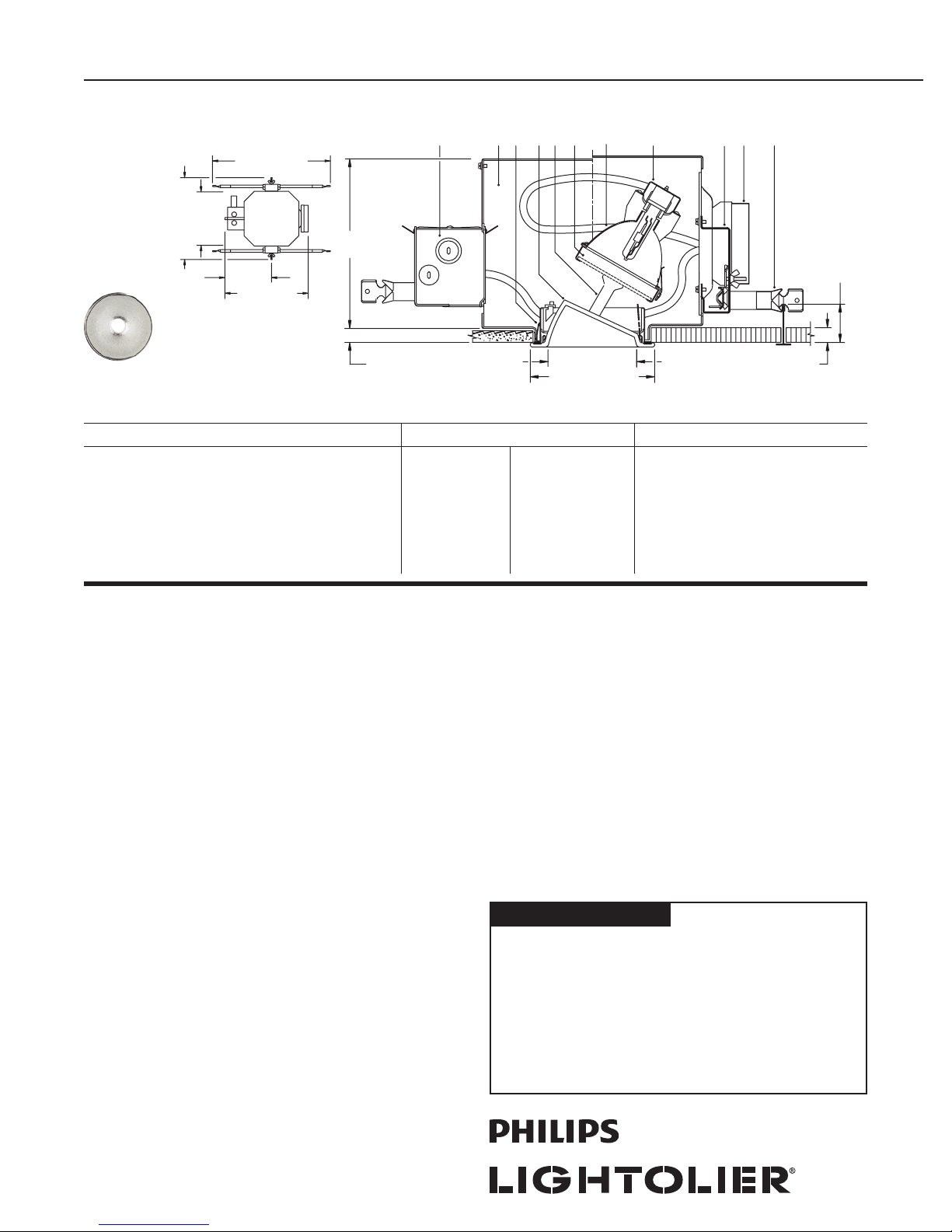
8-1/8" (206 mm)
20" (508 mm) to
30" (762 mm)
10"
(254 mm)
13-7/8" (352 mm)
15" (381 mm)
8" (203 mm)
Top View
Flood
Upper Reflector
Ceiling Cutout: 5 1/8” (130mm) Dia.
For Complete Fix ture Order: Glasslite Trim Kit + Flood Upper Reflector (MHT4RF) + Frame-In Kit. Each Sold Separately.
5/8" (16 mm)
Glasslite Trim Kit + Flood Upper Reflector Frame-In Kit
C4T4GA + MHT4RF (Flood Upper Reflector)
Etched glass, with matching flange.
C4A20BT5PGJ5E1
C4A20T4GU65EU
C4A20T4EU
C4A39T4GU65EU
C4A39T4E1
C4A39T4E2
C4A70T4E1
C4A70T4E2
4-1/8 (105 mm) Dia.
5-1/2" (140 mm) Dia.
Electronic 120V
Electronic 120V/277V
Electronic 120V/277V
Electronic 120V/277V
Electronic 120V
Electronic 277V
Electronic 120V
Electronic 277V
Lamping (Ceramic Metal Halide)
22W Philips MiniMasterColor
20W GE ConstantColor
20W T4.5
39W Philips MiniMasterColor
39W T4.5
39W T4.5
70W T4.5
70W T4.5
6
7
9
1 1/8" (29 mm) max.
Ceiling Thickness
Vertical Adjustment:
3/4" (25 mm) to
2 7/8" (73 mm)
Features
1. Flood Upper Reflector: Specular tex tured aluminum; provides 40° beam.
Interchangeable with 12° Spot (MHT4RS) and 25° Narrow Flood (MHT4RNF);
see spec sheets C4T4GA-MHT4RS and C4T4GA-MHT4RNF.
2. Trim Kit: One piece borosilicate etched glass.
3. Trim Kit Adjustment Mechanism: Provides 35° vertical tilt, 360°
horizontal rotation; lockable. EZ-Aim™ Helical Drive System provides fast and
accurate hot aiming with Philips screwdriver.
4. Socket Housing: Galvanized steel, pre-wired with G8.5 pulse rated
socket. Snaps onto yoke for secure attachment without tools; unitized
construction assures proper alignment of lamp to optics for consistent optical
performance.
5. Frame Housing: Steel, 0.029" (22-Ga.), matte black finish. Removable cover
for top re-lamping.
6. Frame Vertical Adjustment Mechanism: Accommodates mounting to
virtually any ceiling system using pre-installed mounting bars, or 1/2" EMT
tubing (by others). Single locking feature secures all adjustments. Alignment
holes and markings allow fixture to be pre-set prior to installation. Final
adjustment can be made from below from inside fixture.
7. Mounting Bars: Galvanized steel, 0.048" (18-ga.), pre-installed telescoping
bars extend to 30" long and lock securely into position. Built-in locking tabs
provide positive attachment to common T-bar systems. Self-centering feature
simplifies installation in 24" O.C. grid systems. Attaches to steel or wood
joists without accessories.
8. Retention Springs: Rust resistant springs secure trim for quick, tool-less
installation.
9. Ballast / Cover Assembly: Accessible from below and removable without
tools for inspection and ballast replacement .
10. Ju nctio n Box : 0.059" (16-ga.) galvanized steel. UL listed for 8 No. 12 AWG,
90° C through branch circuit conductors. Allows inspection from below.
11. Accessory Holder : Sold separately catalog # CAH4; die-formed steel,
matte black finish, slide-in installation. Accepts up to t wo 3 3/4" dia. media.
Electrical
Electronic Ballast: 120V or 277V, 50/60 Hz., encased, high power factor, T.H.D.
<15%, thermally and transient protected, RMI/RFI complies with FCC Part 18
non-consumer limits, shut-down circuit at end of lamp life, sound rating “A”, -5°F
minimum starting temperature, Type 1 Outdoor rating.
Ballast ANSI Code Voltage Max. Amps Input Watts
20W MH M156 120/277 0.21/0.10 23
39W MH M130 120/277 0.3 9/ 0.17 44
70W MH M139 120/277 0.67/0.29 78
Options and Accessories
Chicago Plenum: Consult Factory
Labels
UL (Suitable for Wet Locations), CSA, I.B.E.W.
Job Information Type:
Job Name:
Cat. No.:
Lamp(s):
Notes:
631 Airport Road, Fall River, MA 02720 • (508) 679-8131 • Fax (508) 674-4710
We reserve the right to change details of design, materials and finish.
www.lightolier.com © 2011 Philips Group • C0711
Page 2
Calculite
®
HID Adjustable Accent C4T4GA-MHT4RF
Page 2 of 4 4 1/2" Aperture, T4.5 Ceramic Metal Halide Glasslite, Flood
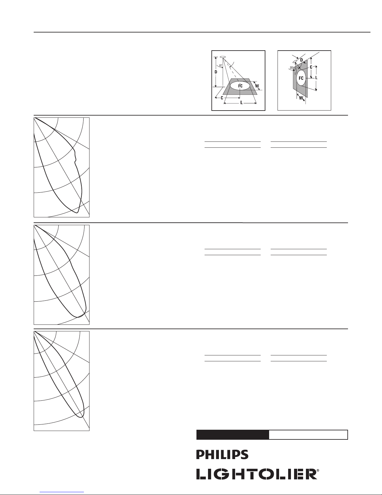
(FC) is initial footcandles at center of
beam. Beam length (L) and beam width (W)
are to where the candlepower is reduced
to 50% of the center beam candlepower.
(C) is the distance to the center of the
beam.
300
600
900
1,200
1,500
2,250
3,000
7,500
11,250
15,000
ANGLE WALL
0 143
5 242
10 456
15 865
20 1120
60°
30°
750
60°
30°
3,750
60°
30°
25 1251
30 1136
35 1003
40 823
45 722
50 650
55 465
60 218
65 46
70 12
75 10
80 8
85 5
90 0
ANGLE WALL
0 274
5 488
10 951
15 1753
20 2432
25 2979
30 2993
35 2595
40 1999
45 1534
50 1173
55 649
60 245
65 64
70 26
75 19
80 6
85 0
90 0
ANGLE WALL
0 141
5 288
10 909
15 2640
20 6497
25 12581
30 15817
35 13798
40 9527
45 6823
50 4410
55 1573
60 338
65 45
70 29
75 18
80 11
85 0
90 0
AIMED 30 deg. TOWARD WALL
LAMP: 20W CERAMIC MH, GE
LUMEN RATING: 1700 LMS.
CBCP: 1251
Beam Angle: 39
AROMAT 20W ELECTRONIC BALLAST
DATE: APR 15, 2004
CERTIFIED TEST REPORT NO. 18686
AIMED 30 deg. TOWARD WALL
LAMP: 39W CERAMIC MH, PHILIPS
LUMEN RATING: 3400 LMS.
CBCP: 2993
Beam Angle: 32
AROMAT 39W ELECTRONIC BALLAST
DATE: APR 13, 2004
CERTIFIED TEST REPORT NO. 18687
AIMED 30 deg. TOWARD WALL
LAMP: 70W CERAMIC MH, PHILIPS
LUMEN RATING: 6200 LMS.
CBCP: 15817
Beam Angle: 22
AROMAT 70W ELECTRONIC BALLAST
DATE: APR 14, 2004
CERTIFIED TEST REPORT NO. 18688
Candlepower Distribution 20W T4.5 - Flood Reflector
30° Aiming Angle
Horizontal Surface
D C FC L W
6' 3.5' 23 5.9' 4.9'
8' 4.6' 13 7.9' 6.5'
10' 5.8' 8 9.9' 8.2'
12' 6.9' 6 11.8' 9.8'
15' 8.7' 4 14.8' 12.3'
Candlepower Distribution
30° Aiming Angle
Horizontal Surface
D C FC L W
8' 4.6' 30 6.3' 5.3'
10' 5.8' 19 7.9' 6.6'
12' 6.9' 14 9.4' 7.9'
15' 8.7' 9 11.8' 9.9'
20' 11.5' 5 15.7' 13.2'
Candlepower Distribution
30° Aiming Angle
Horizontal Surface
D C FC L W
8' 4.6' 161 4.2' 3.6'
10' 5.8' 103 5.2' 4.5'
12' 6.9' 71 6.3' 5.4'
15' 8.7' 46 7.9' 6.7'
20' 11.5' 26 10.5' 9.0'
39W T4.5 - Flood Reflector
70W T4.5 - Flood Reflector
30° Aiming Angle
Vertical Surface
D C FC L W
2' 3.5' 39 9.1' 2.8'
3' 5.2' 17 13.6' 4.2'
4' 6.9' 10 18.2' 5.7'
6' 10.4' 4 27.2' 8.5'
8' 13.9' 2 36.3' 11.3'
30° Aiming Angle
Vertical Surface
D C FC L W
3' 5.2' 42 9.1' 3.4'
4' 6.9' 23 12.2' 4.6'
6' 10.4' 10 18.3' 6.9'
8' 13.9' 6 24.4' 9.2'
12' 20.8' 3 36.5' 13.8'
30° Aiming Angle
Vertical Surface
D C FC L W
3' 5.2' 220 5.3' 2.3'
4' 6.9' 124 7.0' 3.1'
6' 10.4' 55 10.5' 4.7'
8' 13.9' 31 14.0' 6.2'
12' 20.8' 14 21.0' 9.3'
Job Information Type:
631 Airport Road, Fall River, MA 02720 • (508) 679-8131 • Fax (508) 674-4710
We reserve the right to change details of design, materials and finish.
www.lightolier.com © 2011 Philips Group • C0711
Page 3

Calculite
®
HID Adjustable Accent C4T4GA-MHT4RF
Page 3 of 4 4 1/2" Aperture, PGJ5, Glasslite, 40° Flood
22W PGJ5 Philips MiniMastercolor CMH Lamp, Flood Upper Reflector, Lumen Rating = 1650 lms, Aromat Electronic Ballast
Angle Wall
0 198
5 341
500
1000
1500
2000
Certified Test Report No. 3936FR, Date: Oct 16, 2008. Computed by LSI Program **Test-Lite**
10 620
15 952
20 1510
60°
25 2057
30 2352
35 1975
40 1296
45 797
50 382
55 144
60 42
65 14
70 12
75 9
80 7
85 4
30°
90 3
30° Aiming Angle
Horizontal Surface
D C FC L W
6' 3.5' 42 3.5' 2.9'
8' 4.6' 24 4.6' 3.9 '
10' 5.8' 15 5 .8' 4.9'
12' 6.9' 11 6. 9' 5.9 '
15' 8.7' 7 8.6' 7.4'
30° Aiming Angle
Vertical Surface
D C FC L W
2' 3 .5' 74 3.9' 1.7'
3' 5.2' 33 5.9' 2.6'
4' 6.9' 18 7.9' 3.4'
6' 10.4' 8 11.8' 5.1'
8' 13.9' 5 15.7' 6.8'
39W PGJ5 Philips MiniMastercolor CMH Lamp, Flood Upper Reflector, Lumen Rating = 3000 lms, Aromat Electronic Ballast
Angle Wall
0 342
5 596
9000
1800
2700
3600
Certified Test Report No. 3938FR, Date: Oct 16, 2008. Computed by LSI Program **Test-Lite**
10 1071
15 1605
20 2410
60°
25 3174
30 3628
35 3101
40 2105
45 1264
50 584
55 210
60 59
65 20
70 16
75 14
80 9
85 5
30°
90 0
30° Aiming Angle
Horizontal Surface
D C FC L W
6' 3.5' 65 3 .6' 3.1'
8' 4.6' 37 4.8' 4.1'
10' 5.8' 24 6.0' 5.1'
12' 6.9' 16 7.2' 6.1'
15' 8.7' 10 9.0' 7.7'
30° Aiming Angle
Vertical Surface
D C FC L W
2' 3.5' 113 4.2' 1.8'
3' 5.2' 50 6.2' 2.7'
4' 6.9' 28 8 .3' 3. 5'
6' 10.4' 13 12.5' 5.3'
8' 13.9' 7 16.6' 7.1'
631 Airport Road, Fall River, MA 02720 • (508) 679-8131 • Fax (508) 674-4710
We reserve the right to change details of design, materials and finish.
www.lightolier.com © 2011 Philips Group • C0711
Job Information Type:
Page 4

Calculite
®
HID Adjustable Accent C4T4GA-MHT4RF
Page 4 of 4 4 1/2" Aperture, GU6.5, Glasslite, 40° Flood
20W GU6.5 GE Constantcolor CMH Lamp, Flood Upper Reflector, Lumen Rating = 1615 lms, Aromat Electronic Ballast
Angle Wall
0 143
5 255
1000
2000
3000
4000
Certified Test Report No. 3929FR, Date: Oct 16, 2008. Computed by LSI Program **Test-Lite**
10 464
15 716
20 1129
60°
25 1645
30 2006
35 1877
40 1261
45 802
50 396
55 167
60 53
65 14
70 11
75 8
80 7
85 5
30°
90 2
30° Aiming Angle
Horizontal Surface
D C FC L W
6' 3.5' 36 3 .5' 2.9 '
8' 4.6' 20 4.6 ' 3.9'
10' 5.8' 13 5 .8' 4.9'
12' 6.9' 9 6.9' 5.9'
15' 8.7' 6 8.6' 7.4'
30° Aiming Angle
Vertical Surface
D C FC L W
2' 3.5' 63 3 .9' 1.7'
3' 5.2' 28 5.9' 2.6'
4' 6.9' 16 7.9' 3 .4'
6' 10.4' 7 11.8' 5.1'
8' 13.9' 4 15.7' 6.8'
39W GU6.5 GE Constantcolor CMH Lamp, Flood Upper Reflector, Lumen Rating = 3400 lms, Aromat Electronic Ballast
Angle Wall
0 321
5 568
500
1000
1500
2000
Certified Test Report No. 3931FR, Date: Oct 16, 2008. Computed by LSI Program **Test-Lite**
10 1074
15 1668
20 2758
60°
25 3883
30 4646
35 4096
40 2705
45 1663
50 815
55 334
60 100
65 27
70 21
75 16
80 11
85 7
30°
90 2
30° Aiming Angle
Horizontal Surface
D C FC L W
6' 3.5' 84 3.5' 2.9'
8' 4.6' 47 4.6' 3 .9'
10' 5.8' 30 5 .8' 4.9'
12' 6.9' 21 6. 9' 5.9 '
15' 8.7' 13 8.6' 7.4'
30° Aiming Angle
Vertical Surface
D C FC L W
2' 3.5' 145 3.9' 1.7'
3' 5.2' 65 5.9' 2.6'
4' 6.9' 36 7.9' 3.4'
6' 10.4' 16 11.8' 5.1'
8' 13.9' 9 15.7' 6.8'
631 Airport Road, Fall River, MA 02720 • (508) 679-8131 • Fax (508) 674-4710
We reserve the right to change details of design, materials and finish.
www.lightolier.com © 2011 Philips Group • C0711
Job Information Type:
 Loading...