

Philips C500 Service Manual
15” CRT Colour Monitor C500
Service
Service
Service
105E69/05(Samsumg)
Service Manual
HORIZONTAL FREQUENCIES
30-54Khz
TABLE OF CONTENTS
Description Page Description Page
1.0 IMPORTANT SAFETY NOTICE .........................1
2.0 SPECICATION.......................................................2
2.1 CRT DESCRIPTION ................................................. 2
2.2 INTERFACE SIGNALS................................................ 2
2.3 PRESET TIMING.......................................................4
2.4 BRIGHTNESS AND CONTRAST .................................. 4
2.5 POWER CORD .........................................................5
2.6 SIGNAL CABLE......................................................... 5
2.7 INTERNAL CONNECTORS .......................................... 6
2.8 POWER REQUIREMENTS .......................................... 6
2.9 VISUAL CHARACTERISTICS ...................................... 7
2.10 LUMINANCE UNIFORMITY .......................................13
2.11 FUNCTIONAL PERFORMANCE .................................13
2.12 ENVIRONMENT REQUIREMENTS ............................. 13
2.13 RELIABILITY REQUIREMENTS ................................. 14
2.14 WHITE BALANCE ...................................................14
2.15 LUMINANCE UNIFORMITY .......................................15
2.16 FOCUS ................................................................. 15
2.17 IMAGE STABILITY (JITTER) .....................................15
2.18 WARM-UP TIME .................................................... 15
3.0 INTRODUCTION..................................................16
4.0 MECHANICAL INSTRUCTION ...........................17
5.0 ALIGNMENT........................................................22
5.1 B+ VOLTAGE, G1, H. POSITION ADJUSTMENT ........22
5.2 WHITE BALANCE ADJUSTMENT .............................. 22
5.3 FOCUS ADJUSTMENT............................................. 22
5.4 PRESET TIMING ADJUSTMENT................................ 22
6.0 CIRCUIT DESCRIPTION .................................... 23
6.1 GENERAL DESCRIPTION:....................................... 23
6.2
RECTIFIER AND FILTER CKT ........................... 26
6.3
FLYBACK AND PWM CKT ................................. 26
6.4
SNUBBER CKT .................................................. 27
6.5
SYNCHRONIZED CKT....................................... 27
6.6
SYNC RPOCESSOR.......................................... 28
6.7
HOR. PROCESSOR & VERT. PRE-AMP........... 28
6.8
VERTICAL OUTPUT .......................................... 29
6.9
HORIZONTAL DRIVER CIRCUIT....................... 29
6.10
HORIZONTAL OUTPUT STAGE ........................ 29
6.11
FLYBACK TRANSFORMER............................... 29
6.12
VIDEO PRE. AMP............................................... 29
6.13
VIDEO AMPLIFIER............................................. 30
6.14
DIGIT CONTROL ............................................... 30
7.0 REPAIR FLOW CHART...................................... 31
7.1 TROUBLE SHOOTING............................................. 31
7.2
MONITOR CHECK FLOW CHART............................. 32
8.0 DC/AC WAVEFORM MEASUREMENT.............. 35
9.0
PCB LAYOUT ..................................................... 37
9.1 MAIN PCB............................................................ 37
9.2
VIDEO PCB........................................................ 38
SAFETY NOTICE
ANY PERSON ATTEMPTING TO SERVICE THIS CHASSIS MUST FAMILIARIZE HIMSELF WITH THE CHASSIS
AND BE AWARE OF THE NECESSARY SAFETY PRECAUTIONS TO BE USED WHEN SERVICING ELECTRONIC
EQUIPMENT CONTAINING HIGH VOLTAGES.
CAUTION :USE A SEPARATE ISOLATION TRANSFORMET FOR THIS UNIT WHEN SERVICING.
REFER TO BACK COVER FOR IMPORTANT SAFETY GUIDELINES
Published by BCU Monitor Printed in Taiwan Copyright reserved Subject to modification M July 15,2004 GB 8639 000 15714

1
1.0 Important Safety Notice
Proper service and repair is important to the safe, reliable operation of all Philips Consumer
Electronics Company** Equipment. The service procedures recommended by Philips and described
in these service manual are effective methods of performing service operations. Some of these
service operations require the use of tools specially designed for the purpose. The special tools
should be used when and as recommended.
It is important to note that this manual contains various CAUTIONS and NOTICES which should be
carefully read in order minimize the risk of personal injury to service personnel. The possibility exists
that improper service methods may damage the equipment. It is also important to understand that
these CAUTIONS and NOTICES ARE NOT EXHAUSTIVE. Philips could not possibly know, evaluate
and advise the service trade of all conceivable ways in which service might be done or of the possible
hazardous consequences of each way. Consequently, Philips has not undertaken any such broad
evaluation. Accordingly, a servicer who uses a service procedure or procedure or tool which is not
recommended by Philips must first satisfy himself thoroughly that neither his safety nor the safe
operation of the equipment will be jeopardized by the service method selected.
**Hereafter therouhout this manual, Philips Consumer Electronics Company will be referred to as
Philips.
WARNING
Critical components having special safety characteristics are identified with a by the Ref. No. in the
parts list and enclosed within a broken line*
(where several critical components are grouped in one area) along with the safety symbol on the
schematics or exploded views.
Use of substitute replacement parts which do not have the same specified safety characteristics may
create shock, fire, or other hazards.
Under no circumstances should the original design be nodified or altered without written permission
for Philips. Philips assumer no liability, express or implied, arising out of any unauthorized
modification of design.
Servicer assumes all liability.
*Broken Line
FOR PRODUCTS CONTAINING LASER:
DANGER- Invisible laser radiation when open.
AVOLD DIRECT EXPOSURE TO BEAM.
CAUTION- Use of controls or adjustments or performance of procedures other than
those specified herein may result in hazardous radiation exposure.
CAUTION- The use of optical instruments with this product will increase eye hazard.

2
TO ENSURE THE CONTINUED RELIABILITY OF THIS PRODUCT, USE ONLY ORIGINAL
MANUFACTURER’S REPLACEMENT PARTS, WHICH ARE LISTED WITH THEIR PART
NUMBERS IN THE PARTS LIST SECTION OF THIS SERVICE MANUAL.
2.0 Specication
2.1 CRT Description
This display unit shall employ a CRT complying with the following specification:
Size: 15 inches diagonal
Deflection angle: 90 degrees diagonal
Electron gun: In-line type
Focusing method: Electrostatic
Focus lens: Bipotential
Convergence method: Magnetic
Surround type: Black matrix
Array: Dot trios
Trio spacing: 0.28 mm dot pitch
Phosphor type: P22 or equivalent
Phosphor persistence: Medium-short
Light transmission: 57% approx.
Anti reflection: Anti-glare treatment
(45÷65 gloss)
2.2 Interface Signals
This color display shall have an analog video interface and shall be capable to operate with multiple
horizontal and vertical frequencies. Moreover it shall be capable to support compatible DDC1and
DDC2B signals.
2.2.1 Sync Input
Separate, composite TTL compatible
Polarity Positive or negative
2.2.2 Interface Frequency
Table 1:Interface Frequency
3
Horizontal line frequency
(KHZ)±500HZ
Vertical frame frequency
(HZ)±3HZ
31.649 59.94
46.875 75
48.363 60
53.674 85.061
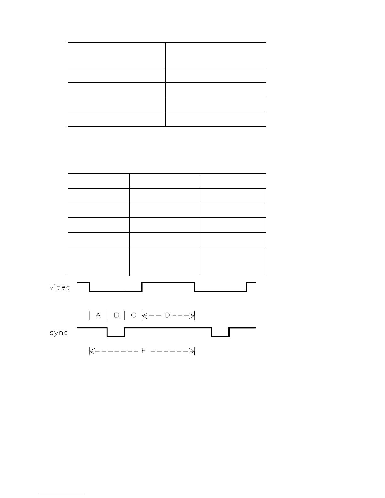
2.2.3 Input Timing Limits
The monitor will accept all timings within the limits of table 2
Table 2: Input Timings Limits
Parameter Horizontal Vertical
Frequency (30 to 54) KHz (50 to 120)Hz
Blanking
≥2.5µs ≥0.4ms
Back Porch
≥1.0µs ≥0.1ms
Front Porch
≤back Porch ≤Back Porch
Sync Pulse
≥0.7µs
<0.3ms
>0.03ms
4
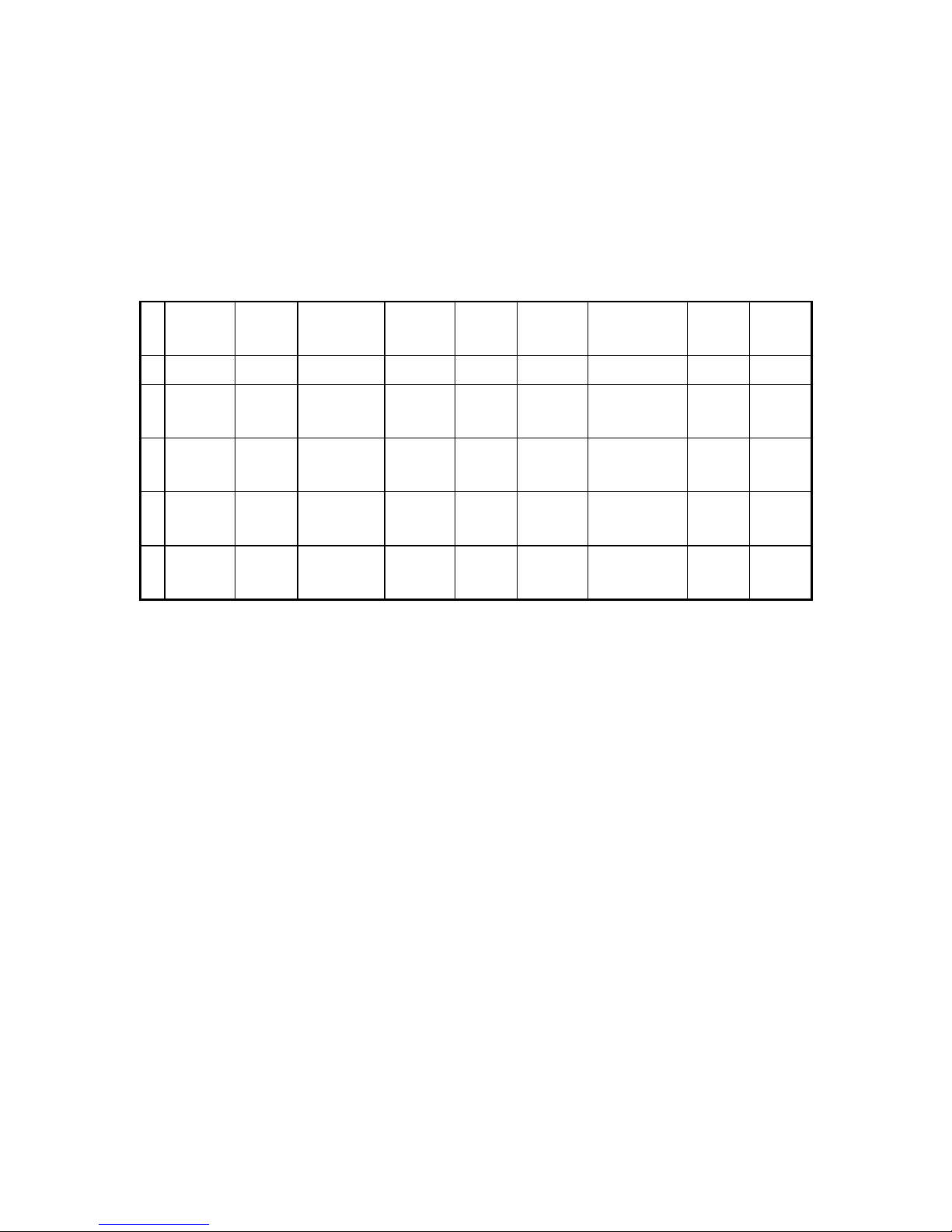
2.3 Preset Timing
M454 U-P Default Timing
Table 3
sweep F D C B A
MODE H Pixes
V Lines
Fd(MHz)
Polar(H/V)
Fh(KHz)
Fv(Hz)
Th(us)
Tv(ms)
Td(us)
Td(ms)
Tb(us)
Tb(ms)
Tp(us)
Tp(ms)
Tf(us)
Tf(ms)
d: dot d: display b: backporch p: pulse f: front
1
VGA60 640
480
25.175
N/N
31.469
59.94
31.777
16.683
25.422
15.253
1.907
1.049
3.813
0.064
0.635
0.317
2
VESA75 800
600
49.5
P/P
46.875
75
21.333
13.333
16.162
12.8
3.232
0.448
1.616
0.064
0.323
0.021
3
VESA60 1024
768
65
N/N
48.363
60
20.677
16.667
15.754
15.88
2.462
0.6
2.092
0.124
0.369
0.063
4
VESA85 800
600
56.25
P/P
53.674
85.061
18.631
11.756
14.222
11.179
2.702
0.503
1.138
0.056
0.569
0.018
2.4 Brightness and Contrast
Definitions:
Active area This zone can be lighted when the background color is changed from
black to any other color. Its dimensions, in terms of timing correspond to
the "active area "times described in table 3
Raster area Under certain conditions (see table 4) this zone must be visible when no video input is
applied. Width and height of the raster area must be larger than the corresponding
dimensions of the active area.
Border Comprising any area of the screen outside the raster area.
Brightness This control is mainly intended as a raster luminance adjustment.
Contrast This control shall vary the gain of the video amplifier, thus adjusting the contrast
of the displayed images, and shall not have any visible effect on the raster luminance.
Both controls shall not affect the border. Inside this zone the raster shall be always under the minimum
perceptible level and no evidence of retracing(images or distortion)shall be visible on the screen at any
5
setting of the luminance controls. The user controls shall operate as described on table 4. This check
must be performed under a diffused illumination of 10 lux and on 48k mode (Horizontal frequency).
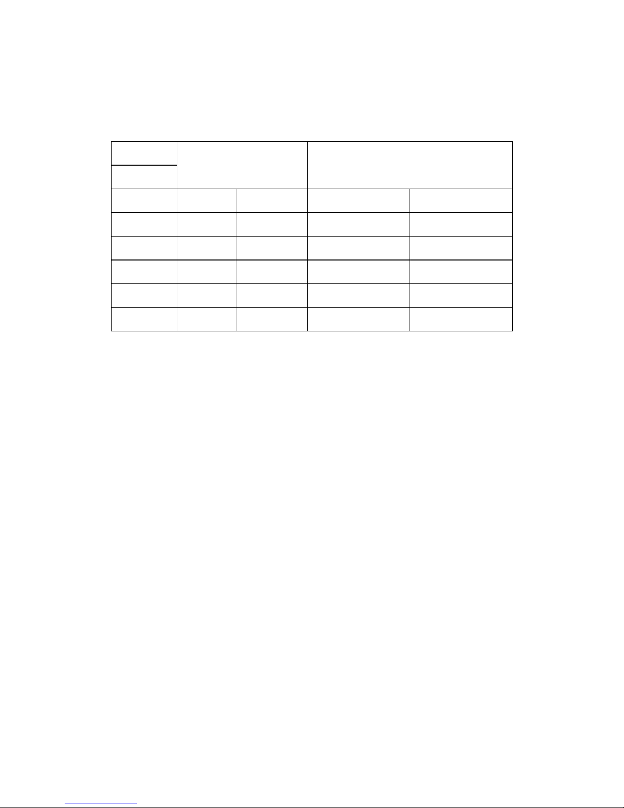
Table 4
Patterns Setting of user Controls Luminance Limits
Brightness Contrast Raster Area White Area
A Min Any Not Visible *
A Max Min 0.3 ~ 3.0 FL *
B Max Max * 60 FL<=
C Max Max *
>27FL
B Min Max Not Visible Visible
B Min Min Not Visible Not Visible
Legend:
*Don't Care
A Black screen @0 mV video level.
B 2″ x 2 ″white box, @700mV video level.
C Full white screen, 100% of the data area @700mV video level
.
Power inlet
Power shall be applied to the display device through a standard three wire receptacle NEMA
A/5261 or equivalent.
2.5 Power cord
The power cord supplied with the monitor must conform to the International Standards described
on part 8.0 and shall have physical and electrical characteristics such that to comply with any other
specification item. The power cord shall be of removable type.
2.6 Signal cable
Signals shall be applied to the display device through a shielded cable, which must be intended as
part of monitor. This cable shall be of a suitable type in order to comply with any specific item, and
shall be terminated in a 15 pin D-Shell male connector type AMP 211350-1 or equivalent, with pin
assignment as follows:
15 pin mini D-sub
1 Red video input
2 Green video input
3 Blue video input

6
4 Identify output
5 Ground
6 Red video ground
7 Green video input
8 Blue video ground
9 Not connected
10 Logic ground
11 Identify output
12 SDA (DDC1 or DDC2B)
13 Horizontal sync.
14 Vertical sync. (VCLK)
15 SCL (DDC2B)
2.7 Internal connectors
All internal connectors for the interconnection of sub assemblies must be distinct in their physical
characteristics or polarization so as to prevent any misconnection which may cause permanent
damage to the display.
2.8 Power Requirements
The display device shall maintain the specified performances in the range described below:
Frequency: 50/60Hz ± 3Hz
Voltage: 90 to 264 Vac RMS
The following consumption requirements shall be met:
Power consumption: 75W for MPRII & VLMF Yoke
70W for NORMAL Yoke
Current consumption: 1.2 Aac RMS
Note:
Current and power consumption are the maximum values allowed in the voltage ranges describe
above.
2.8.1 Power Management
Table 5: Power Management
NO STATE STATE POWER SAVING
HORIZONTAL VERTICA VIDEO
7
1 ON PLUSES PLUSES ACTIVE NONE
2 STAND-BY NO PLUSES PLUSES BLANKED
<15W@90~240VAC
3 SUSPEND PLUSES NO PLUSES BLANKED
<15W@90~240VAC
4 OFF NO PLUSES NO PLUSES BLANKED
<5W@90~240VAC
The states of power saving function shall be display by LED indication.
2.9 Visual Characteristics
All factory preset resolutions must guarantee the right display dimension and centering. Other
resolutions can be adjusted correctly with the external controls as per section 2.5.
In all resolution must be possible to adjust the monitor in full screen (overscan mode) by external
controls. The viewing eye angle while performing any dimensional measurement is parallel to the axis
of the picture tube.
2.9.1 Test Conditions
Resolution: any of preset modes
Input level: 700 mV
Pattern: crosshatch after setting full white pattern with
20FL luminance.(Except otherwise indicated)
Brightness control: cutoff position
Contrast control: position after setting full white pattern with 20FL luminance.
Unless otherwise specified, the display shall meet the requirements of this section under any
combination of the following operating ranges:
Image duty cycle: 10% to 90%
Input power: As per section 3.1
Operating temperature: As per section 6.2
Humidity: As per section 6.2
Magnetic field: Horizontal=0 Gauss
Vertical=0.4 Gauss
2.9.2 Display Dimensions
The dimensions of the data area for all presetting mode listed in part 2.3.1,measured along the
8
horizontal and vertical axes of the screen, shall be as follows:
Horizontal=270 ± 4mm
Vertical=203± 4mm
The external control ranges of the data area, shall be as follows:
Maximum horizontal size: overscan the screen
Minimum horizontal size: ≤255mm
Maximum vertical size: overscan the screen
Minimum vertical size: ≤183mm
2.9.3 Picture Size Variation
The change in display size shall be less than 3mm in width or 2mm in height at full white
pattern.(250x188mm
2
)
Brightness change from 5FL to 25FL
Temperature change in 25°C ±10°C
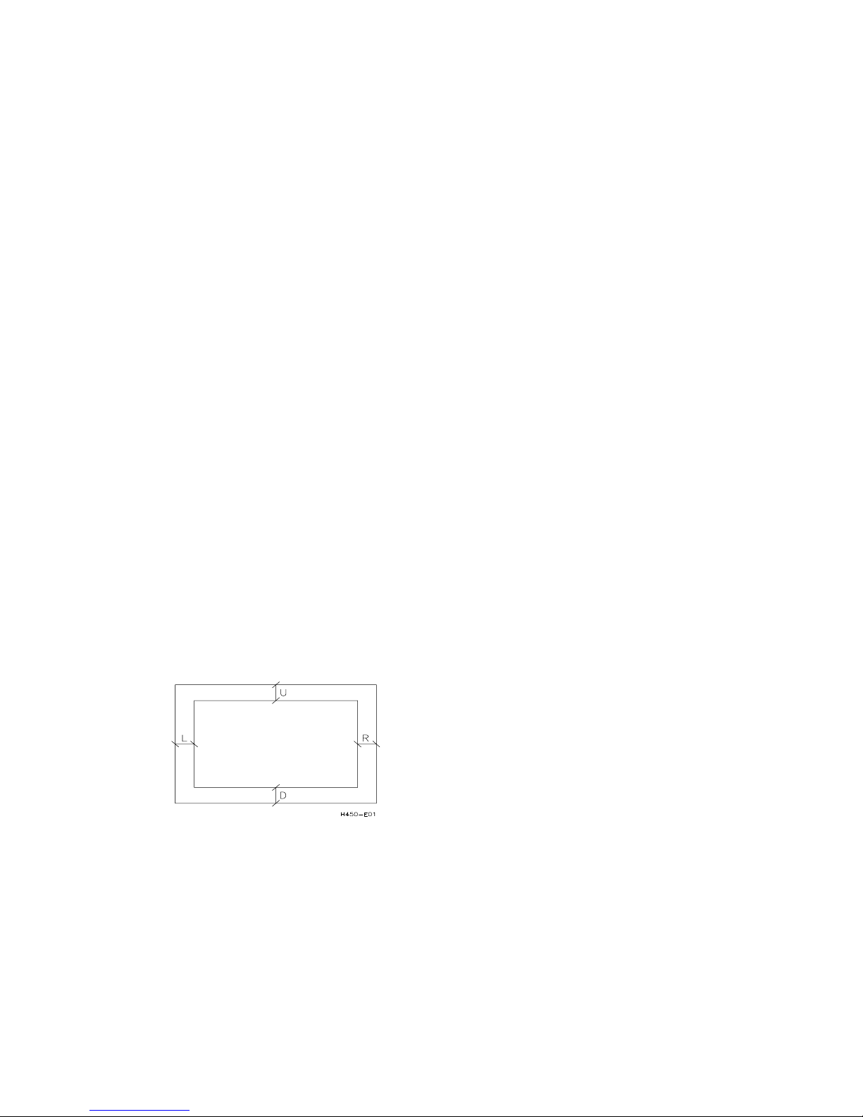
2.9.4 Display Centering
Figure 9. Describes the pattern for this test. Basically a single pixel white line around the perimeter
of the data area composes it, with marks for the horizontal ad vertical axes. The background is
black.
The maximum variation of the display centering shall be such that the following relationship shall be
met:
a | L - R | ≤ 3mm | U - D | ≤3mm
Figure 9: Display Centering
The external control ranges of display position for all modes listed in part 2.3.1 shall be as follows:
Horizontal position: total control range≥ 40mm
Vertical position: total control range≥ 25mm
9
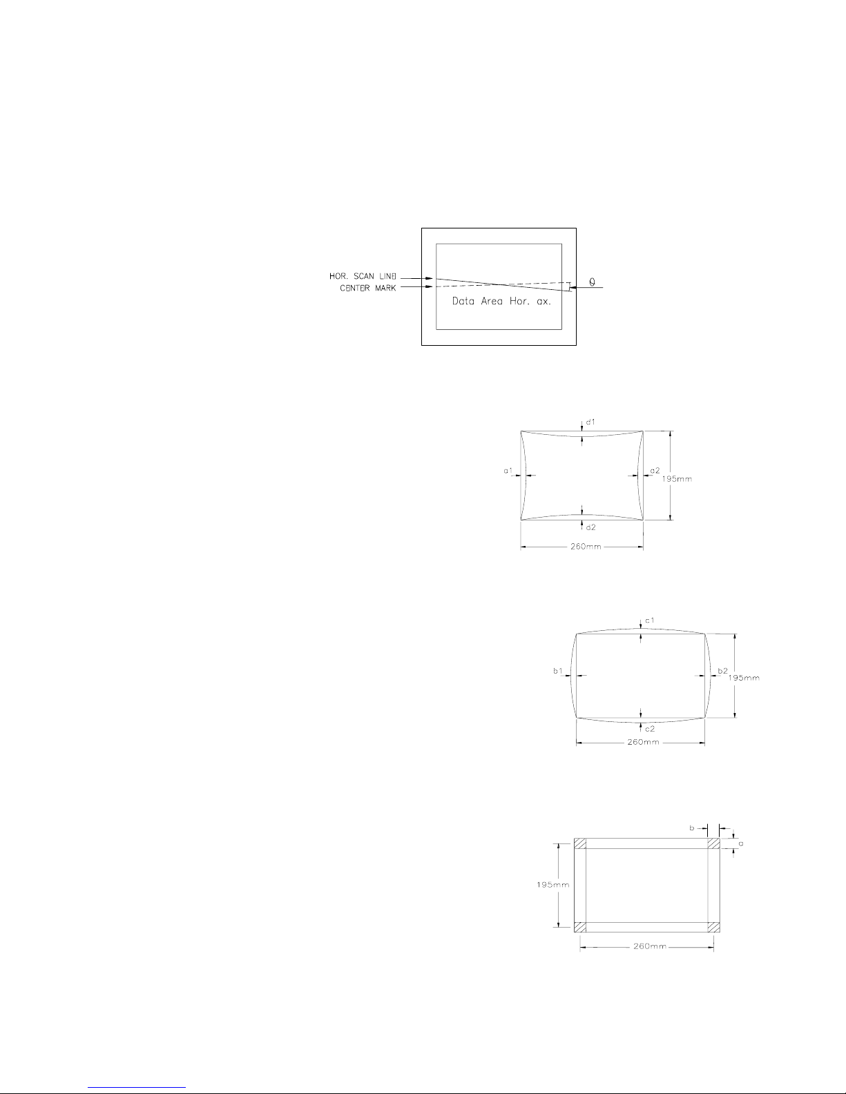
2.9.5 Tilt
The maximum variation of the display rotation (tilt) shall be such that the following relationship shall
be met:
θ≤0.5 degree
2.9.6 Geometric Distortions
1. Pincushion
Pincushion(top) d1≤1.5mm
Pincushion(bottom) d2≤1.5mm
Pincushion(leftside) a1≤1.5mm
Pincushion(rightside) a2≤1.5mm
"S" distortion ≤0.5mm
2. Barrel
barrel(top) c1≤1.5mm
barrel(bottom) c2≤1.5mm
barrel(leftside) b1≤1.0mm
barrel(rightside) b2≤1.0mm
3. Trapezoid & Parallelogram distortion
a≤2.0mm
b≤2.5mm
10
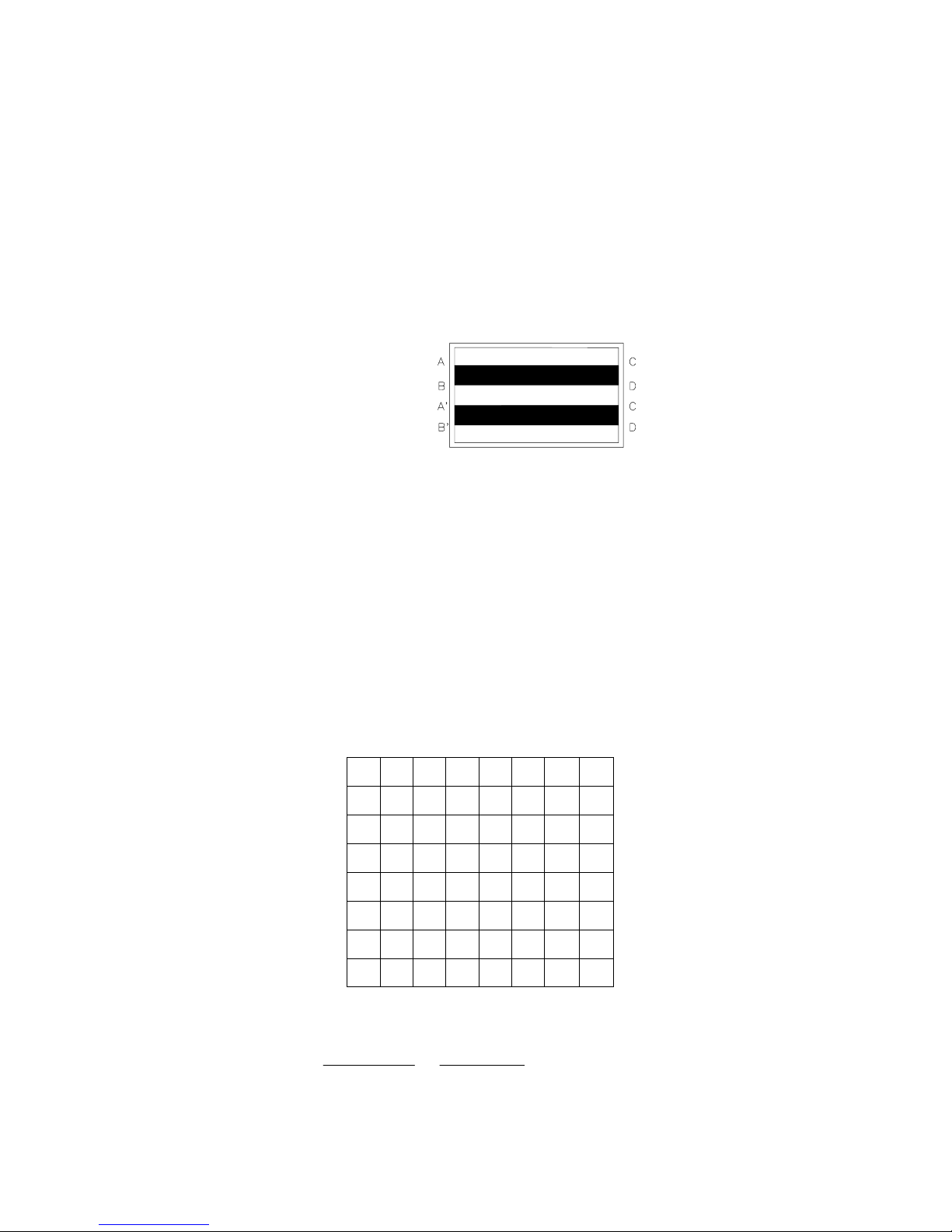
2.9.7 Geometric Distortion By Luminance
The test pattern is composed of two white areas and a black area, the three areas are equivalents.
The input signal level is 700 mV with brightness control at cut-off and contrast control at
maximum(see Figure 12).
The distortion introduced by dynamic High Voltage variation, due to different brightness level on the
screen, are admitted with following limits:
|AC - BD| or |A'C'-B' D'|≤2.0mm
Figure 12
2.9.8 Linearity
The linearity of an image displayed on the CRT must meet the following requirements, with
reference to figure 13 for both X and Y axis.
The measured value of linearity shall be less than 6% when calculated using all lattices and shall be
less than 4% when calculated using adjacent lattices.
X1 X2 X3 X4 X5 X6 X7 X8
Y1
Y2
Y3
Y4
Y5
Y6
Y7
Y8
mi
n
max
minmax
mi
n
max
minmax
YY
YY
OR
X
XXX+
−
+
−
11
Figure 13:Linearity
Where: X max and X min are belong to the set Xi,i=1......8
X max, X min, be Calculated Same Line
Y max, Y min, be Calculated Same Row
Y max and Y min are belong to the set Yi,i=1....8
2.9.9 Misconvergence
The display must conform to all the following requirements:
Maximum convergence error.
Area Horizental Direction Vert. Direction
A
Center field of 203mm diameter
0.30mm 0.30mm
B
Square field of 270 x 203 mm
0.40mm 0.40mm
Table 6 : Misconvergence
The maximum convergence error shall be measured for a white spot or line, and represents the
maximum distance between the energy centers of any two primary colors. The central area is
defined as the area within a circle centered on the CRT faceplate having a diameter equal to the
display vertical dimension.
Figure 14
2.9.10 Image Stability (Jitter)
Not perceivable Jitter will be present on the display, when displaying a cross-hatch pattern, at a
distance of 500 mm from the screen. In any case it is not admitted a measured Jitter value greater
than one dot (both on X axis or on Y axis).

12
2.9.11 White Color Adjustment
The chromaticity coordinates of the white color shall be verified with standard full white screen
@700 mV input level with brightness control at cut-off and contrast control adjusted to 25FL nits of
luminance on the center of the screen. The 1931 CIE chromaticity diagram (x, y) coordinates for the
screen center shall be:
x = 0.283± 0.030
y = 0.297± 0.030
2.9.12 White Color Uniformity
With a standard full white screen as described in section 4.11, the color coordinates measured at
any point of the screen shall be:
x = Xref ± 0.030
y = Yref ± 0.030
2.9.13 White Color Tracking
Contrast Control Tracking Error
After performing the standard setting as described in section 4.11, the contrast control shall be
moved within 30FL (max) and 7FL (min) of screen luminance or to the mechanical stop if the lower
limit cannot be reached. The white color coordinates in the center of the CRT when displaying the
standard pattern at all the allowed setting of the contrast control shall be:
x = Xref ± 0.035
y = Yref ± 0.035
Brightness Control Tracking Error
The initial setting shall be as follows:
Pattern: white raster
Input level: 700mV
Brightness control: maximum
Contrast control: adjust to 100 nit of screen luminance in the center of the CRT
The brightness control shall be moved within 30FL (max) and 7FL (min) of screen luminance or to
the mechanical stop if the these limits cannot be reached. The white color coordinates in the center
of the CRT at all the allowed settings of the brightness control shall be:
x = Xref ± 0.035
y = Yref ± 0.035

13
2.10 Luminance Uniformity
The variation in average display luminance between any area(with dimension approximate 2 cm of
diameter)on standard flat white screen, must be less than 35% of the luminance of the brightest
area with brightness control at cut-off and contrast control adjusted to 80 nits of luminance on the
center of screen.
2.10.1 Focus
When external contrast control is adjusted for 20±1FL light output with a flat white field pattern, then
switch to a character pattern filled with "H" characters, the characters shall be readable and
distinguishable.
2.10.2 Moire
While displaying a white raster, no Moire effect shall be visible at any luminance setting 15FL.
2.10.3 Purity
Conspicuous miss-landing shall not be visible within display area. at distance of 60cm from CRT
surface at 20FL white luminance.
2.11 Functional Performance
2.11.1 Acoustical noise:
The acoustical noise shall be less than 50dB when operating in normal condition, mode change or
power on/off.
2.11.2 Turn off:
Set unit at 20FL of full white screen, then turn off unit, image should disappear smoothly, no
persistent spot and flash.
2.11.3 High voltage discharge:
The arcing due to monitor high voltage discharge shall not cause any damage to devices connected
to the monitor.
2.11.4 Tapping test:
No objectionable intermittence or noise occur while tapping top, left right, rear side of enclosure by
a rubber hammer.
2.12 Environment Requirements
2.12.1 Non-adjusting operation
25℃ ± 10℃
2.12.2 Operating
Temperature 0°C to +40°C

14
Relative Humidity 10% to 90%
Altitude Sea level to 8,000ft
2.12.3 Storage of shipment
Temperature -20°C to + 60°C
Relative Humidity 10% to 90%
Altitude Sea level to 40,000ft
2.12.4 TEST PROCEDURUE:
• Put in temperature chamber under 60°C Time: 24 hours
• Back to room temperature Time: 4 hours
• Put in temperature chamber under -20°C Time: 24 hours
• Back to room temperature Time: 4 hours
• The process repeat 2 times.
2.13 Reliability Requirements
2.13.1 Mean Time Before Failure ( MTBF )
30,000 hours with 90% confidence level.(CRT less)
2.13.2 Reference Document
MIL-STD-105D
MIL-HDBK-217E
2.13.3 Electro-Static Discharge ( ESD )
Contact discharge:
Apply 6KV,the set must be auto-recovery
Apply 4KV,the display pattern doesn’t appear noise
Air discharge:
Apply 8KV,be disallow components damage or EEPROM data loss
Apply 6KV,the display pattern does not appear noise.
2.14 White Balance
Set the external BRIGHTNESS at the point that raster just cut off, adjust CONTRAST over the range
from 5F-L to 20F-L, or reversed, with full-intensity reverse pattern, the color coordinate, measured by
MINOLTA TV-COLOR ANALYZER-II (TV-2130), shall be within the limitation listed below:
x=0.283
0.03
y=0.297
0.03 (At 5 F-L and 20 F-L)

15
2.15 Luminance Uniformity
The variation in average display luminance between any area(with dimension approximate 2 cm of
diameter)on standard flat white screen, must be less than 35% of the luminance of the brightest area
with brightness control at cut-off and contrast control adjusted to 80 nits of luminance on the center of
screen.
2.16 Focus
When external contrast control is adjusted for 15+/-1FL light output with a flat white field pattern, then
switch to a character pattern filled with "H" characters, the characters shall be readable and disting
uishable.
2.17 Image Stability (Jitter)
Not perceivable Jitter will be present on the display, when displaying a cross-hatch pattern, at a
distance of 500 mm from the screen. In any case it is not admitted a measured Jitter value greater
than one dot (both on X axis or on Y axis).
2.18 Warm-Up Time
The warm-up time shall be 20 minutes maximum. At the end of the warm-up period, no adjustment or
service shall be necessary to cause the display to meet the requirements contained herein. After a
warm-up time of 1 minute, the display shall produce a usable image. Repetitive power ON/OFF
cycles must be possible with a minimum switch-off time of about 4s.

16
3.0 INTRODUCTION
This document is related to a 15" CRT color monitor MC500 to be used with various kinds of graphic
adapters, including IBMVGA, VESAVGA, ERGOVGA, SVGA, UVGA and XGA modes. It is intended
as a mutisync monitor type based on microprocessor unit, capable to support all the video standards.
This monitor, simply adjusting image size and centering by means of the user controls gathered on
the front panel, can support other graphic standards. The monitor is used with 30KHZ to 54KHZ
frequency in horizontal sweep while vertical refresh rate is from 50HZ to 120HZ.
Moreover it offers Power Management and DDC1 and DDC2B features according to VESA
recommendations.
17
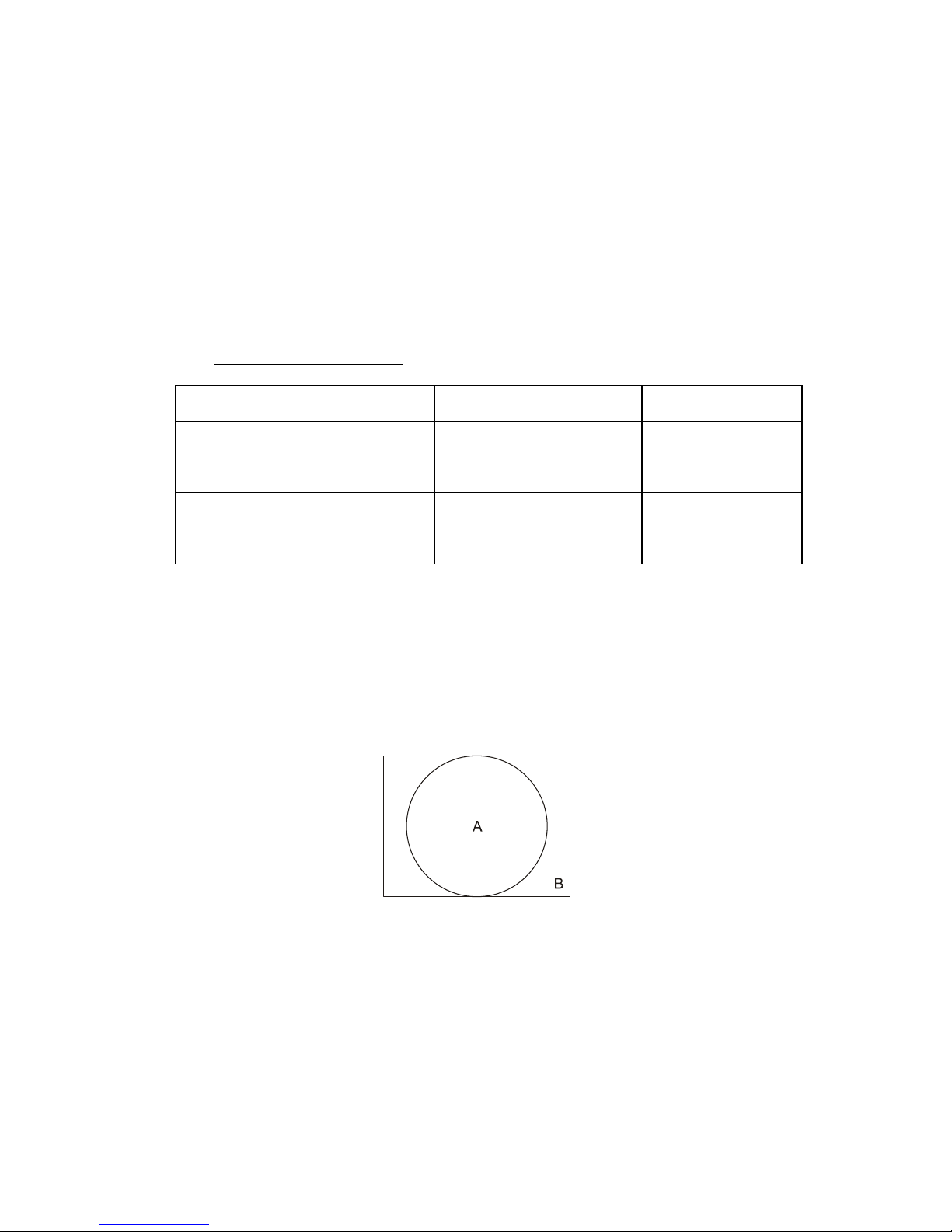
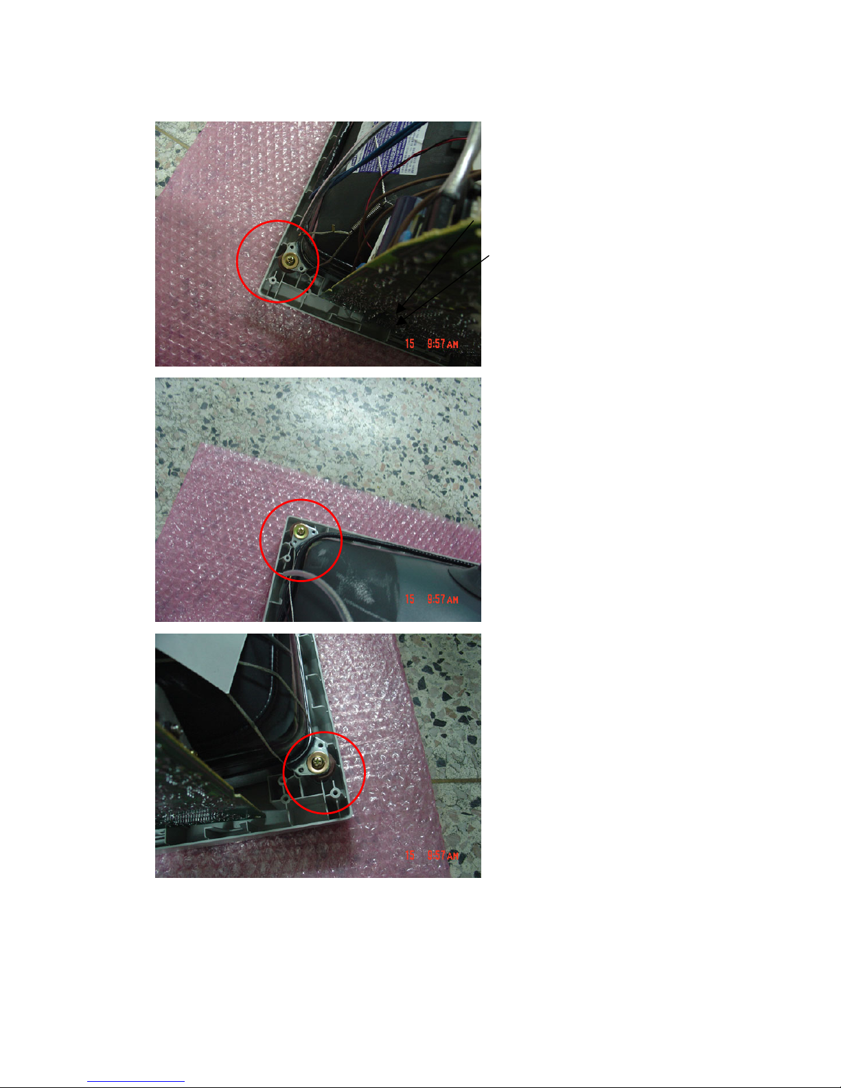
4.0 MECHANICAL INSTRUCTION
Remove base
Push the hook to remove base.
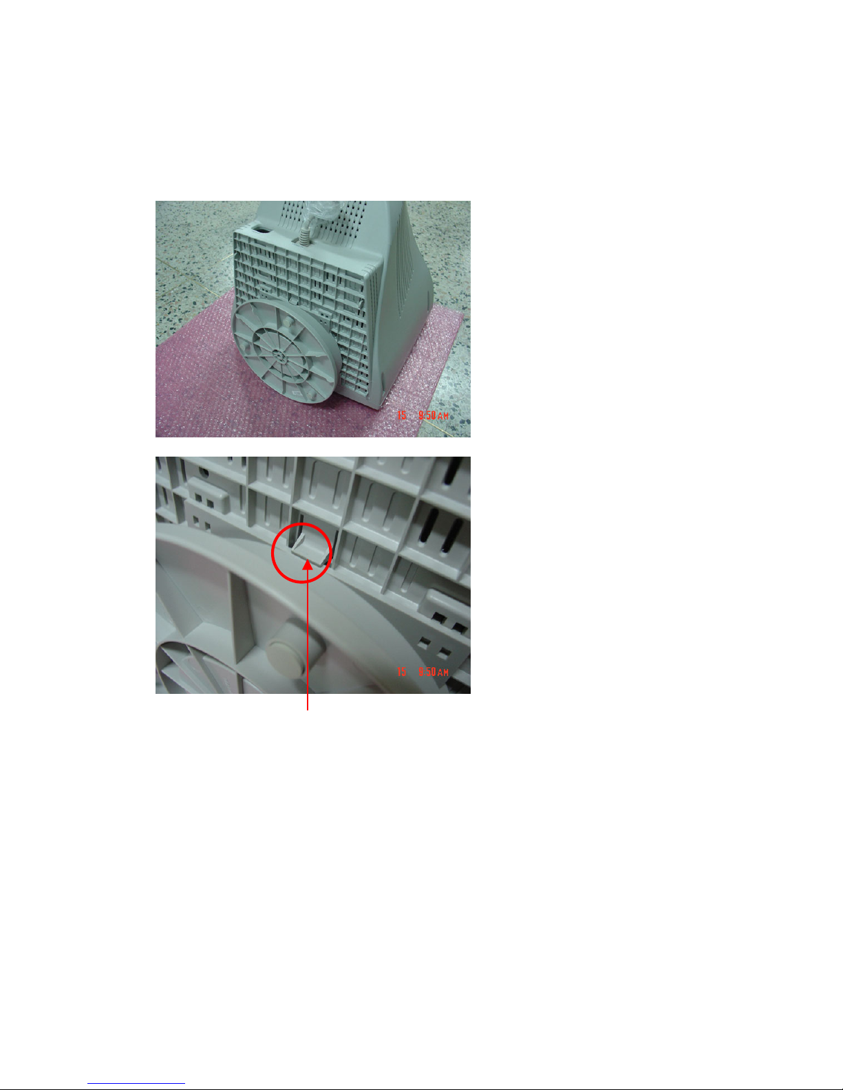
18
Remove 4 screws between bezel and back cover.
19
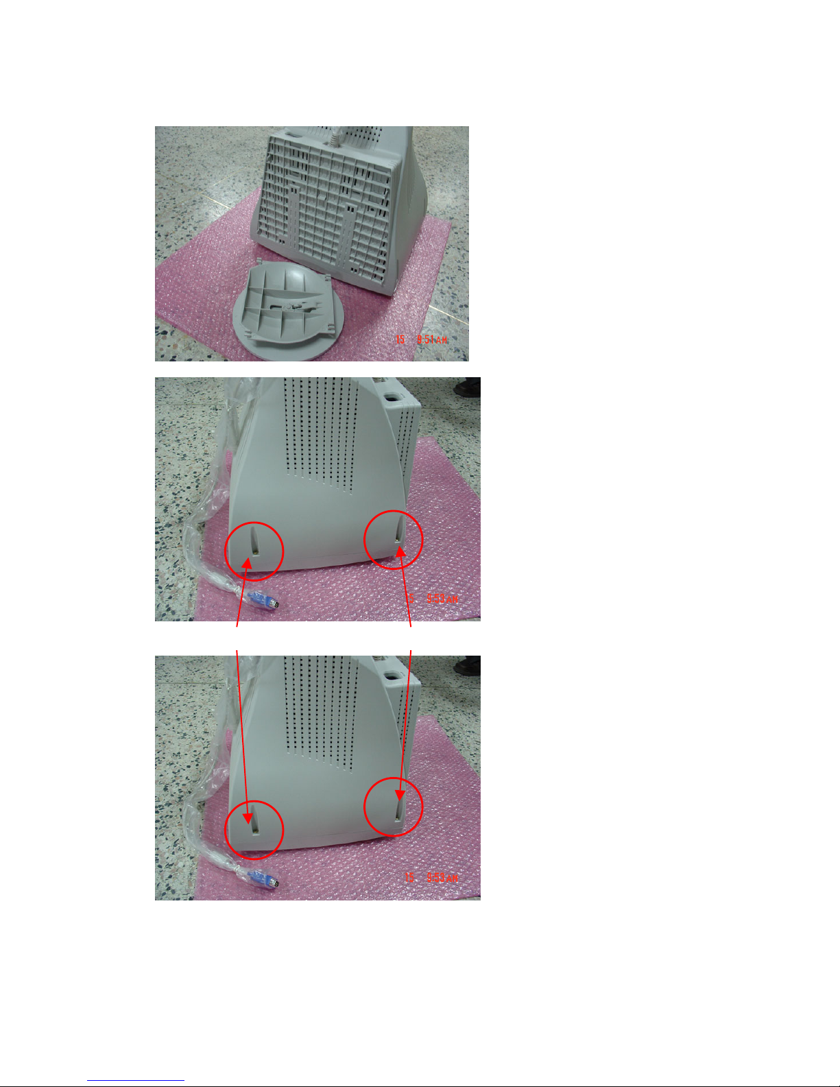
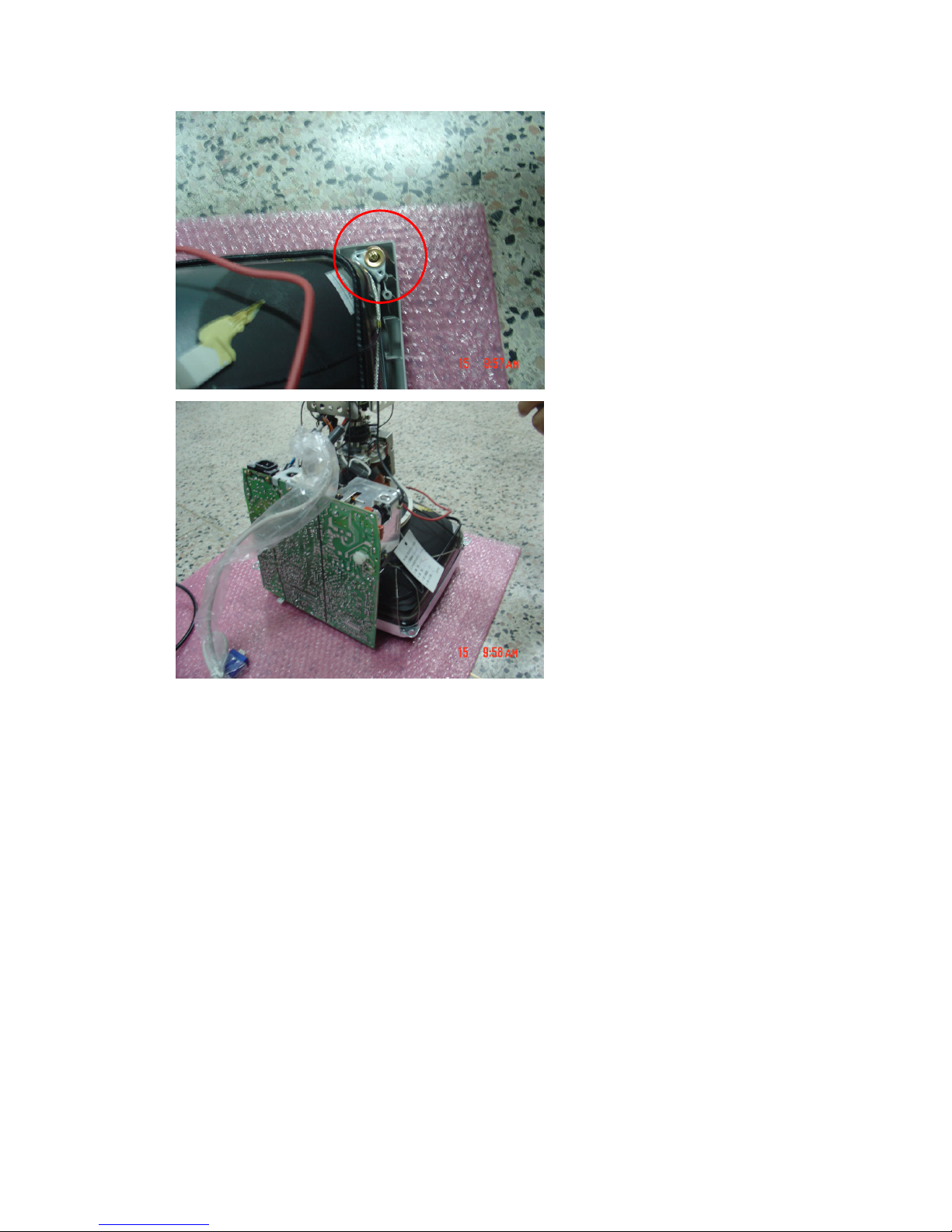
Remove back cover
Remove 4 screws to remove guild L & R
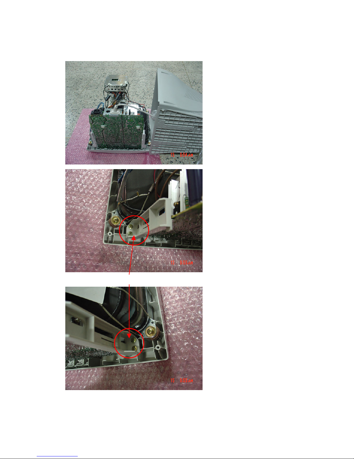
20
Remove 4 screws to remove bezel
21

22
5.0 ALIGNMENT
Warm up the monitor for at least 30 minutes before adjustment.
• Set the front of CRT to the east.
• Turn all VR set to center position.
5.1 B+ Voltage, G1, H. Position Adjustment
Use front control key adjust the display size about 270mm, adjust VR501 let the voltage of FBT
PIN3 cathode is 130±0.3V. (Timing is 48k 1024x768.Pattern is full white.)
5.2 White Balance Adjustment
• EXT. BRIGHTNESS and EXT. CONTRAST set MAX.
1. Input timing 48k 1024x768 without pattern adjust G2 VR (mounting on F.B.T) so that the
brightness of back raster to become 0.5± 0.1 FL.
2. Adjust Brightness to cut-off (Raster), then adjust VR801 let the brightness is 45 ± 1FL
(2” pattern).
3. Adjust Bri & Cont. to max, then adjust VR802 let the brightness is 29 ± 1FL (Full white).
4. All the value must be check repeatedly.
5.3 Focus Adjustment
1. EXT. BRIGHTNESS move to cut off point. Use EXT.CONTRAST set the brightness to
25FL.
2. Adjust Focus VR (mounting on F.B.T), to get best focus.
5.4 Preset Timing Adjustment
(Short P102 or press recall key when power on)
1. Input each PRESET MODE timing, and use front control key adjust the display to the
normal position and size, and wait for 2 seconds.
2. Switch to next timing repeat 1 process. Unitl every PRESET MODE timing have been
adjusted
 Loading...