

Philips bym358x DATASHEETS
Philips Semiconductors Product specification
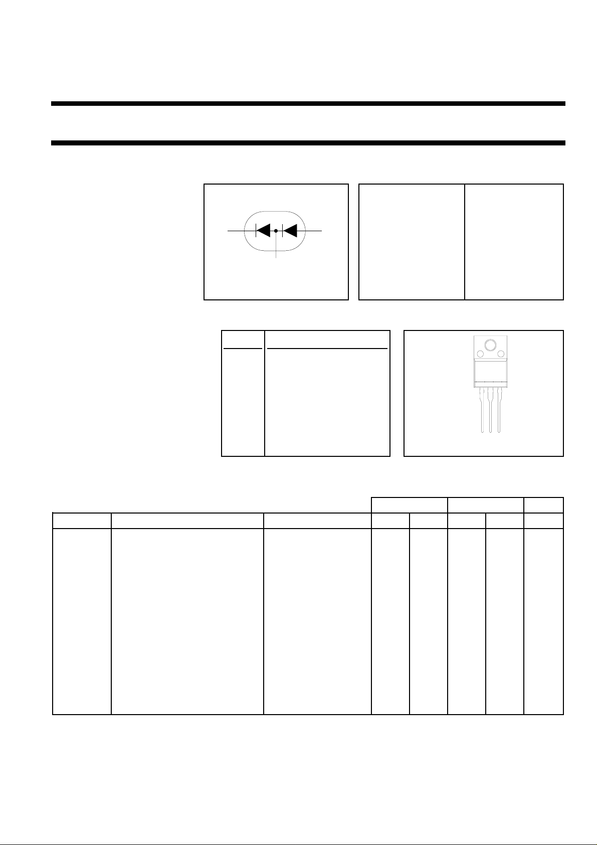
Damper-Modulator BYM358X
fast, high-voltage
FEATURES SYMBOL QUICK REFERENCE DATA
• Low forward volt drop DAMPER MODULATOR
• Ultra fast switching
• Soft recovery characteristic VR=1500 V VR=600 V
• High thermal cycling
performance VF ≤ 1.5 V VF ≤ 1.08 V
• Isolated mounting tab
GENERAL DESCRIPTION PINNING SOT186A
damper modulator
1
2
3
I
=7 A I
F(peak)
I
≤ 66 A I
FSM
F(peak)
FSM
= 7 A
≤ 70 A
trr ≤ 170 ns trr ≤ 60 ns
Combined damper and modulator PIN DESCRIPTION
diodes in an isolated plastic
case
envelopeforhorizontaldeflectionin 1 damper cathode
PC monitors.
The BYM358X contains diodes 2 common anode/cathode
with performance characteristics
designed specifically for 3 modulator anode.
applications from 32kHz to 120kHz
The BYM358X series is supplied in
123
the conventional leaded SOT186A
package.
LIMITING VALUES
Tj = 25 ˚C unless otherwise stated
DAMPER MODULATOR
SYMBOL PARAMETER CONDITIONS MIN MAX MIN MAX UNIT
V
RSM
V
RRM
V
RWM
I
F(peak)
I
F(RMS)
Peak non-repetitive reverse - 1500 - 600 V
voltage.
Peak repetitive reverse voltage - 1500 - 600 V
Crest working reverse voltage - 1300 - 600 V
Peak forward current 31-70 kHz monitor. - 7 - 7 A
RMS forward current sinusoidal;a=1.57 - 15.7 - 14.1 A
I
FSM
Peak non-repetitive forward t = 10 ms - 60 - 70 A
current t = 8.3 ms - 66 - 77 A
sinusoidal;with
reapplied
V
RWM(MAX)
T
stg
T
J
Storage temperature -40 150 -40 150 ˚C
Operating junction temperature - 150 - 150 ˚C
March 2000 1 Rev 1.000

Philips Semiconductors Product specification
Damper-Modulator BYM358X
fast, high-voltage
ISOLATION LIMITING VALUE & CHARACTERISTIC
Ths = 25 ˚C unless otherwise specified
SYMBOL PARAMETER CONDITIONS MIN. TYP. MAX. UNIT
V
isol
C
isol
THERMAL RESISTANCES
SYMBOL PARAMETER CONDITIONS TYP. MAX. TYP. MAX. UNIT
R
th j-hs
R.M.S. isolation voltage from all f = 50-60 Hz; sinusoidal - - 2500 V
three terminals to external waveform;
heatsink R.H. ≤ 65% ; clean and dustfree
Capacitance from T2 to external f = 1 MHz - 10 - pF
heatsink
DAMPER MODULATOR
Thermal resistance junction to with heatsink - 4.8 - 5.5 K/W
heatsink compound
R
th j-a
Thermal resistance junction to in free air. 55 - 55 - K/W
ambient
STATIC CHARACTERISTICS OF DAMPER
Tj = 25 ˚C unless otherwise stated
SYMBOL PARAMETER CONDITIONS TYP MAX. UNIT
V
F
Forward voltage IF = 6.5 A 1.3 1.6 V
IF = 6.5 A; Tj = 125˚C 1.2 1.5 V
I
R
Reverse current VR = V
VR = V
RWM
RWM
10 100 µA
300 500 µA
Tj = 100 ˚C
STATIC CHARACTERISTICS OF MODULATOR
Tj = 25 ˚C unless otherwise stated
SYMBOL PARAMETER CONDITIONS TYP MAX. UNIT
V
F
I
R
Forward voltage IF = 8 A 1.2 1.3 V
IF = 8 A; Tj = 150˚C 0.95 1.08 V
IF = 20 A 1.3 1.45 V
Reverse current. VR = V
VR = V
Tj = 100 ˚C
RWM
RWM
10 50 µA
100 350 µA
March 2000 2 Rev 1.000

Philips Semiconductors Product specification
Damper-Modulator BYM358X
fast, high-voltage
ELECTRICAL CHARACTERISTICS OF DAMPER
Tj = 25 ˚C unless otherwise stated
SYMBOL PARAMETER CONDITIONS TYP. MAX. UNIT
t
rr
Q
s
V
fr
ELECTRICAL CHARACTERISTICS OF MODULATOR
Tj = 25 ˚C unless otherwise stated
SYMBOL PARAMETER CONDITIONS TYP. MAX. UNIT
t
rr
I
rrm
Q
s
V
fr
Reverse recovery time IF = 1 A; VR ≥ 30 V; 130 170 ns
-dIF/dt = 50 A/µs
Reverse recovery charge 2 A,30 V,20 A/µs 0.65 0.9 µC
Peak forward recovery voltage IF = 6.5 A; 29 - V
dIF/dt = 50 A/µs
Reverse recovery time IF = 1 A; VR ≥ 30 V; 35 60 ns
/dt = 100 A/µs
-dI
F
Peak reverse recovery current IF = 10 A to VR ≥ 30 V; 3.0 5.5 A
dIF/dt = 50 A/µs; Tj = 100˚C
Reverse recovery charge 2 A,30 V,20 A/µs4070nC
Peak forward recovery voltage IF = 10 A; 5.0 - V
dIF/dt = 10 A/µs
March 2000 3 Rev 1.000
 Loading...