

Philips BY559X-1500U Datasheet
Philips Semiconductors Product specification
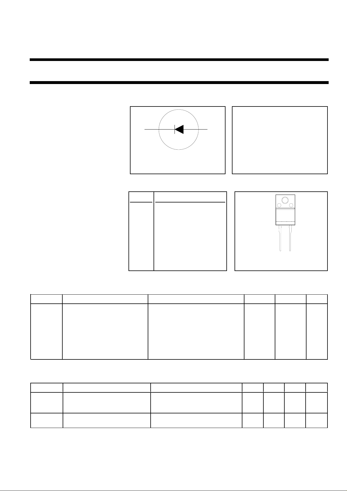
Damper diode BY559X-1500U
ultra fast, high-voltage
FEATURES SYMBOL QUICK REFERENCE DATA
• Low forward volt drop VR = 1500 V
• Low forward recovery voltage
• Ultra Fast switching VF ≤ 1.5 V
• Soft recovery characteristic
• High thermal cycling performance Vfr ≤ 8 V
• Low thermal resistance
GENERAL DESCRIPTION PINNING SOD113
k a
12
I
trr ≤ 130 ns
I
= 10 A
FWM
≤ 160 A
FSM
A double diffused rectifier diode in PIN DESCRIPTION
a plastic envelope, featuring ultra
case
fast forward and reverse recovery 1 cathode
andlowforwardvoltage.Thedevice
is intended for use as a damper 2 anode
diode in horizontal deflection
circuits of large screen monitors case isolated
and workstations in applications up
to 150kHz.
12
The BY559seriesis suppliedin the
conventional leaded SOD59 and
SOD113 packages.
LIMITING VALUES
Limiting values in accordance with the Absolute Maximum System (IEC 134).
SYMBOL PARAMETER CONDITIONS MIN. MAX. UNIT
V
V
I
FWM
I
FRM
I
FSM
T
T
RRM
RWM
stg
j
Peak repetitive reverse voltage - 1500 V
Crest working reverse voltage - 1300 V
Peak working forward current f = 120 kHz; - 10 A
Peak repetitive forward current t = 100 µs - 150 A
Peak non-repetitive forward t = 10 ms - 160 A
current sinusoidal; Tj = 150 ˚C prior to
surge; with reapplied V
RWM(max)
Storage temperature -40 150 ˚C
Operating junction temperature - 150 ˚C
ISOLATION LIMITING VALUE & CHARACTERISTIC
Ths = 25 ˚C unless otherwise specified
SYMBOL PARAMETER CONDITIONS MIN. TYP. MAX. UNIT
V
isol
C
isol
April 1999 1 Rev 1.100
R.M.S. isolation voltage from f = 50-60 Hz; sinusoidal - 2500 V
both terminals to external waveform;
heatsink R.H. ≤ 65% ; clean and dustfree
Capacitance from both terminals f = 1 MHz - 10 - pF
to external heatsink

Philips Semiconductors Product specification
Damper diode BY559X-1500U
ultra fast, high-voltage
THERMAL RESISTANCES
SYMBOL PARAMETER CONDITIONS MIN. TYP. MAX. UNIT
R
th j-hs
R
th j-a
STATIC CHARACTERISTICS
Tj = 25 ˚C unless otherwise stated
SYMBOL PARAMETER CONDITIONS MIN. TYP. MAX. UNIT
V
F
I
R
DYNAMIC CHARACTERISTICS
Tj = 25 ˚C unless otherwise stated
SYMBOL PARAMETER CONDITIONS MIN. TYP. MAX. UNIT
V
fr
t
fr
t
rr
Q
s
Thermal resistance junction to with heatsink compound - - 4.8 K/W
heatsink
Thermal resistance junction to in free air - 55 - K/W
ambient
Forward voltage IF = 6.5 A - 1.7 2.05 V
IF = 6.5 A; Tj = 125 ˚C - 1.2 1.5 V
Reverse current VR = V
VR = V
RWMmax
; Tj = 125 ˚C - - 2.0 mA
RWMmax
- - 0.5 mA
Forward recovery voltage IF = 6.5 A; dIF/dt = 50 A/µs-68V
Forward recovery time IF = 6.5 A; dIF/dt = 50 A/µs; VF = 5 V - 130 180 ns
Reverse recovery time IF = 1 A; -dIF/dt = 50 A/µs; VR ≥ 30 V - 100 130 ns
Reverse recovery charge IF = 2 A; -dIF/dt = 20 A/µs; VR ≥ 30 V - 0.2 0.3 µC
April 1999 2 Rev 1.100
 Loading...