

Philips BUK854-800A Datasheet
Philips Semiconductors Product Specification
Insulated Gate Bipolar Transistor (IGBT) BUK854-800A
GENERAL DESCRIPTION QUICK REFERENCE DATA
Fast-switching N-channel insulated SYMBOL PARAMETER MAX. UNIT
gate bipolar power transistor in a
plastic envelope. V
The device is intended for use in I
motor control, DC/DC and AC/DC P
converters, and in general purpose V
high frequency switching E
CE
C
tot
CEsat
off
applications.
PINNING - TO220AB PIN CONFIGURATION SYMBOL
Collector-emitter voltage 800 V
Collector current (DC) 12 A
Total power dissipation 85 W
Collector-emitter on-state voltage 3.5 V
Turn-off Energy Loss 0.5 mJ
PIN DESCRIPTION
tab
c
1 gate
2 collector
3 emitter
tab collector
123
g
e
LIMITING VALUES
Limiting values in accordance with the Absolute Maximum System (IEC 134)
SYMBOL PARAMETER CONDITIONS MIN. MAX. UNIT
V
V
±V
I
C
I
C
I
CLM
I
CM
P
T
T
CE
CGR
GE
tot
stg
j
Collector-emitter voltage - -5 800 V
Collector-gate voltage RGE = 20 kΩ - 800 V
Gate-emitter voltage - - 30 V
Collector current (DC) Tmb = 25 ˚C - 12 A
Collector current (DC) Tmb = 100 ˚C - 6 A
Collector Current (Clamped Tj ≤ T
jmax.
-20A
Inductive Load) VCL ≤ 500 V
Collector current (pulsed peak value, Tj ≤ T
jmax.
-30A
on-state)
Total power dissipation Tmb = 25 ˚C - 85 W
Storage temperature - - 55 150 ˚C
Junction Temperature - - 150 ˚C
THERMAL RESISTANCES
SYMBOL PARAMETER CONDITIONS TYP. MAX. UNIT
R
th j-mb
R
th j-a
October 1994 1 Rev.1.100
Junction to mounting base - - 1.47 K/W
Junction to ambient In free air 60 - K/W

Philips Semiconductors Product Specification
Insulated Gate Bipolar Transistor (IGBT) BUK854-800A
STATIC CHARACTERISTICS
Tmb = 25 ˚C unless otherwise specified
SYMBOL PARAMETER CONDITIONS MIN. TYP. MAX. UNIT
V
(BR)CES
V
GE(TO)
I
CES
I
CES
I
ECS
I
GES
V
CEsat
DYNAMIC CHARACTERISTICS
Tmb = 25 ˚C unless otherwise specified
SYMBOL PARAMETER CONDITIONS MIN. TYP. MAX. UNIT
g
fe
C
ies
C
oes
C
res
t
d on
t
r
E
on
t
d off
t
f
E
off
t
d on
t
r
E
on
t
d off
t
f
E
off
Collector-emitter breakdown VGE = 0 V; IC = 0.25 mA 800 - - V
voltage
Gate threshold voltage VCE = VGE; IC = 1 mA 3 4 5.5 V
Zero gate voltage collector VCE = 800 V; VGE = 0 V; Tj = 25 ˚C - 10 100 µA
current
Zero gate voltage collector VCE = 800 V; VGE = 0 V; Tj =125 ˚C - 0.1 1 mA
current
Reverse collector current VCE = -5 V; VGE = 0 V - 0.1 5 mA
Gate emitter leakage current VGE = ±30 V; VCE = 0 V - 10 100 nA
Collector-emitter saturation VGE = 15 V; IC = 6 A - 2.4 3.5 V
voltage VGE = 15 V; IC = 12 A - 3.1 - V
Forward transconductance VCE = 15 V; IC = 3 A 1.5 4 - S
Input capacitance VGE = 0 V; VCE = 25 V; f = 1 MHz - 400 750 pF
Output capacitance - 45 80 pF
Feedback capacitance - 15 40 pF
Turn-on delay time IC = 6 A; VCC = 500 V; - 20 - ns
Turn-on rise time VGE = 15 V; RG = 25Ω; - 30 - ns
Turn-on Energy Loss Tj = 25˚C; - 0.25 - mJ
Turn-off delay time Inductive Load - 170 270 ns
Turn-off fall time Energy Losses include all ’tail’ - 200 400 ns
Turn-off Energy Loss losses - 0.25 0.5 mJ
Turn-on delay time IC = 6 A; VCC = 500 V; - 20 - ns
Turn-on rise time VGE = 15 V; RG = 25Ω; - 30 - ns
Turn-on Energy Loss Tj = 125˚C; - 0.25 - mJ
Turn-off delay time Inductive Load - 200 350 ns
Turn-off fall time Energy Losses include all ’tail’ - 400 800 ns
Turn-off Energy Loss losses - 0.5 1 mJ
October 1994 2 Rev.1.100
Philips Semiconductors Product Specification
Insulated Gate Bipolar Transistor (IGBT) BUK854-800A
Zth j-mb / (K/W)
1E+01
1E+00
D =
0.5
0.2
1E-01
1E-02
1E-03
0.1
0.05
0.02
p
t
P
0
1E-07 1E-05 1E-03 1E-01 1E+01
D
t / s
D =
T
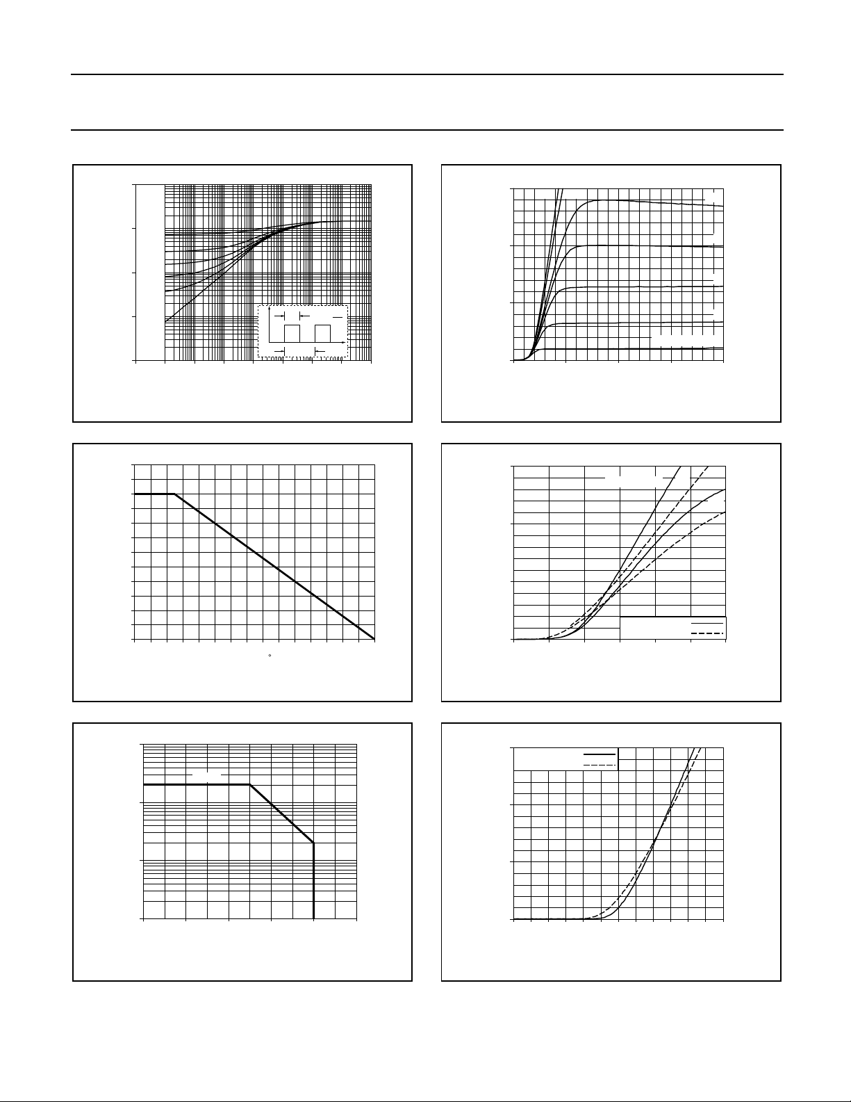
Fig.1. Transient thermal impedance
Z
= f(t) ; parameter D = tp/T
th j-mb
PD%
120
110
100
90
80
70
60
50
40
30
20
10
0
0 20 40 60 80 100 120 140
Normalised Power Derating
Tmb / C
Fig.2. Normalised power dissipation.
PD% = 100.PD/P
D 25˚C
= f(Tmb)
IC / A
30
20
p
t
T
t
10
0
20 15
0 10 20
515
VCE / V
BUK8Y4-800A
10
9
8
7
VGE / V = 6
Fig.4. Typical output characteristics, Tj=25 ˚C.
IC=f(VCE); parameter V
IC / A
30
VGE / V =
20
10
0
135
0 2 4 6
VCEsat / V
GE
BUK8Y4-800A
15
10
Tj / C = 25
150
Fig.5. Typical on-state characteristics
IC=f(VCE); parameters Tj,V
GE
IC / A BUK854-800
100
ICLM
10
1
0.1
0 200 400 600 800 1000
VCE / V
Fig.3. Turn-off Safe Operating Area
conditions: Tj ≤ T
; RG = 50
jmax.
Ω
IC / A
30
Tj / C = 25
150
20
10
0
0 2 4 6 8 10 12
VGE / V
BUK8Y4-800A
Fig.6. Typical transfer characteristics
IC=f(VGE) ; conditions: VCE=15 V; parameter T
j
October 1994 3 Rev.1.100
 Loading...