

Philips BT1308-400D, BT1308-600D Technical data
查询BT1308-400D供应商查询BT1308-400D供应商
M3D186
1. Product profile
1.1 Description
1.2 Features
BT1308-400D/600D
Logic level triac
Rev. 01 — 19 February 2004 Product data
Logic level sensitive gate triac intended to be interfaced directly to microcontrollers,
logic integrated circuits and other low power gate trigger circuits.
■ Sensitive gate in all four quadrants ■ Low cost package.
1.3 Applications
■ General purpose bidirectional
switching
■ Solid state relays ■ Low power AC fan speed controllers.
■ Phase control applications
1.4 Quick reference data
■ V
■ I
≤ 600 V (BT1308-600D) ■ V
DRM
≤ 9A ■ I
TSM
DRM
T(RMS)
2. Pinning information
Table 1: Pinning - SOT54 (TO-92), simplified outline and symbol
Pin Description Simplified outline Symbol
1 main terminal 2
2 gate
3 main terminal 1
1
2
3
SOT54 (TO-92)
MSB033
≤ 400 V (BT1308-400D)
≤ 0.8 A.
1
2
MBL305
3

Philips Semiconductors
BT1308-400D/600D
Logic level triac
3. Ordering information
Table 2: Ordering information
Type number Package
Name Description Version
BT1308-600D TO-92 Plastic single-ended leaded (through hole) package; 3 leads SOT54
BT1308-400D TO-92 Plastic single-ended leaded (through hole) package; 3 leads SOT54
4. Limiting values
Table 3: Limiting values
In accordance with the Absolute Maximum Rating System (IEC 60134).
Symbol Parameter Conditions Min Max Unit
V
DRM
I
T(RMS)
I
TSM
2
tI
I
dI
T
I
GM
V
GM
P
GM
P
G(AV)
T
stg
T
j
repetitive peak off-state voltage
BT1308-600D 25 °C ≤ T
≤ 125 °C - 600 V
j
BT1308-400D - 400 V
on-state current (RMS value) full sine wave; T
≤ 55 °C; Figure 1 and 2 - 0.8 A
lead
non-repetitive peak on-state current full sine wave; Tj=25°C prior to surge;
Figure 3 and 4
t=20ms - 9 A
t = 16.7 ms - 10 A
2
t for fusing t = 10 ms - 0.32 A2s
/dt repetitive rate of rise of on-state
current after triggering
ITM= 1 A; IG= 0.2 A; dIG/dt = 0.2 A/µs
T2+ G+ - 50 A/µs
T2+ G− -50A/µs
T2− G− -50A/µs
T2− G+ - 10 A/µs
gate current (peak value) t = 2 µs max - 1 A
gate voltage (peak value) - 5 V
gate power (peak value) - 5 W
average gate power t = 2 µs max; T
≤ 80 °C - 0.1 W
case
storage temperature −40 +150 °C
junction temperature −40 +125 °C
9397 750 12594
Product data Rev. 01 — 19 February 2004 2 of 11
© Koninklijke Philips Electronics N.V. 2004. All rights reserved.
Philips Semiconductors
BT1308-400D/600D
Logic level triac
T
lead
003aaa616
(°C)
I
T(RMS)
(A)
1
0.75
0.5
0.25
0
0 50 100 150
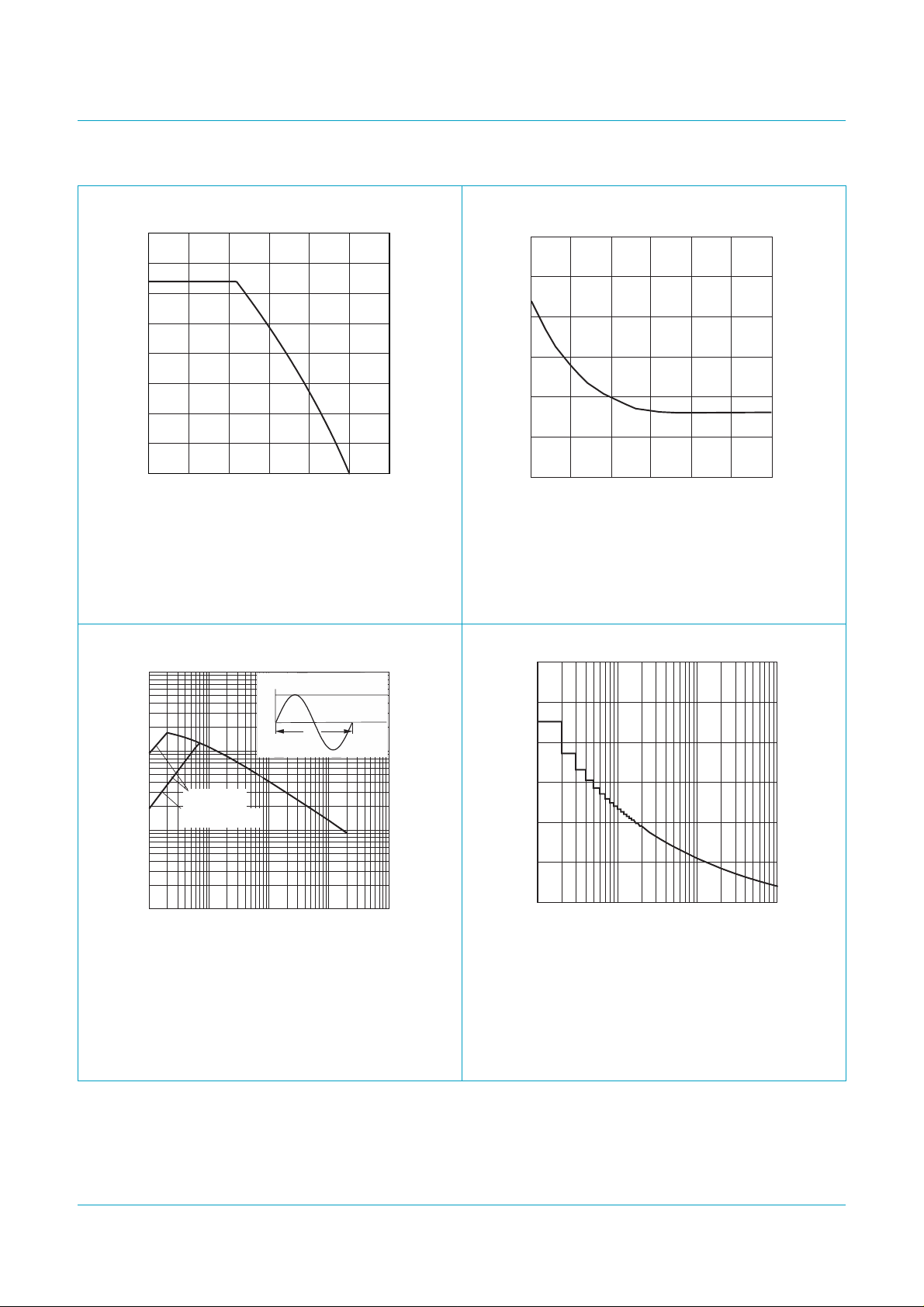
Fig 1. Maximum permissible on-state current (RMS
value) as a function of lead temperature.
003aaa614
I
TSM
t
p
time
I
TSM
(A)
3
10
2
10
I
T
003aaa617
1
t
surge
(s)
10
I
T(RMS)
(A)
3
2
1
0
-3
10
-2
10
f = 50 Hz
T
≤ 65 °C
lead
Fig 2. Maximum permissible repetitive on-state
current (RMS value) as a function of surge
duration for sinusoidal currents.
003aaa615
I
TSM
(A)
12
8
dIT/dt limit
-5
10
T2- G+ quadrant
10
1
tp≤ 20 ms
initial Tj≤ 25 °C
-4
10
-3
10
-2
10
tp (s)
-1
10
4
0
11010210
n = number of cycles
f = 50 Hz
3
n
initial Tj≤ 25 °C
Fig 3. Maximum permissible non-repetitive peak
on-state current as a function of pulse width for
sinusoidal currents.
9397 750 12594
Fig 4. Maximum permissible non-repetitive peak
on-state current as a function of number of
cycles for sinusoidal currents.
© Koninklijke Philips Electronics N.V. 2004. All rights reserved.
Product data Rev. 01 — 19 February 2004 3 of 11
Philips Semiconductors
BT1308-400D/600D
Logic level triac
5. Thermal characteristics
Table 4: Thermal characteristics
Symbol Parameter Conditions Min Typ Max Unit
R
th(j-lead)
R
th(j-a)
thermal resistance from junction to lead full cycle - - 60 K/W
half cycle 80
thermal resistance from junction to ambient mounted on a printed-circuit board;
- 150 - K/W
lead length = 4 mm; Figure 5
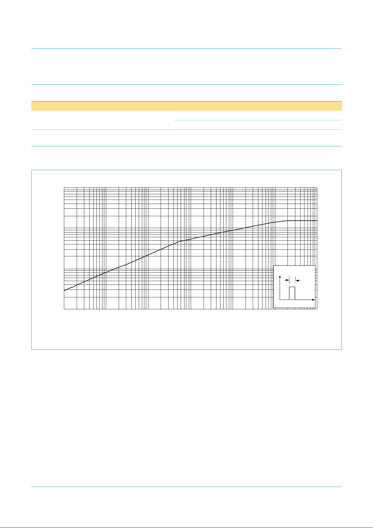
5.1 Transient thermal impedance
t
p
tp (s)
003aaa029
t
10
Z
th(j-a)
(K/W)
3
10
2
10
10
P
1
-5
10
-4
10
-3
10
-2
10
-1
10
1
Fig 5. Transient thermal impedance from junction to ambient as a function of pulse duration; typical values.
9397 750 12594
© Koninklijke Philips Electronics N.V. 2004. All rights reserved.
Product data Rev. 01 — 19 February 2004 4 of 11
 Loading...