

Philips br100 DATASHEETS

Philips Semiconductors Product Specification
Silicon Bi-directional Trigger Device BR100/03
GENERAL DESCRIPTION QUICK REFERENCE DATA
Siliconbidirectionaltrigger device in a SYMBOL PARAMETER MIN. MAX. UNIT
glass envelope intended for use in
triac and thyristor trigger circuits. V
V
I
(BO)
O
FRM
OUTLINE - SOD27 SYMBOL
LIMITING VALUES
Limiting values in accordance with the Absolute Maximum System (IEC 134).
SYMBOL PARAMETER CONDITIONS MIN. MAX. UNIT
I
P
T
T
FRM
tot
stg
j
Repetitive peak forward t ≤ 10 µs, Ta ≤ 50˚C; f = 60 Hz - 2 A
current
Total power dissipation Ta = 50˚C - 150 mW
Storage temperature -55 125 ˚C
Operating junction - 100 ˚C
temperature
Breakover voltage 28 36 V
Output voltage 7 - V
Repetitive peak forward current - 2 A
THERMAL RESISTANCES
SYMBOL PARAMETER CONDITIONS MIN. TYP. MAX. UNIT
R
th j-a
Thermal resistance junction to in free air - 330 - K/W
ambient
R
th j-lead
Thermal resistance junction to - 150 - K/W
leads
CHARACTERISTICS
Ta = 25 ˚C unless otherwise stated.
SYMBOL PARAMETER CONDITIONS MIN. TYP. MAX. UNIT
V
(BO)
|V
| - |V
(BO)+
V
O
I
(BO)
dV
/dT Temperature coefficient of - 0.1 - %/K
(BO)
t
r
Breakover voltage I = I
| Breakover voltage symmetry I = I
(BO)-
Output voltage RL = 20 Ω; Circuit of fig: 2 7 - - V
Breakover current V = V
V
(BO)
Risetime Ip = 0.5 A; Circuit of fig: 2 - 1.5 µs
(BO)
, see fig: 1 - - 3.5 V
(BO)
(BO)
28 32 36 V
--50µA
February 1996 1 Rev 1.100
Philips Semiconductors Product Specification
Silicon Bi-directional Trigger Device BR100/03
I
V(BO)III
I(BO)III
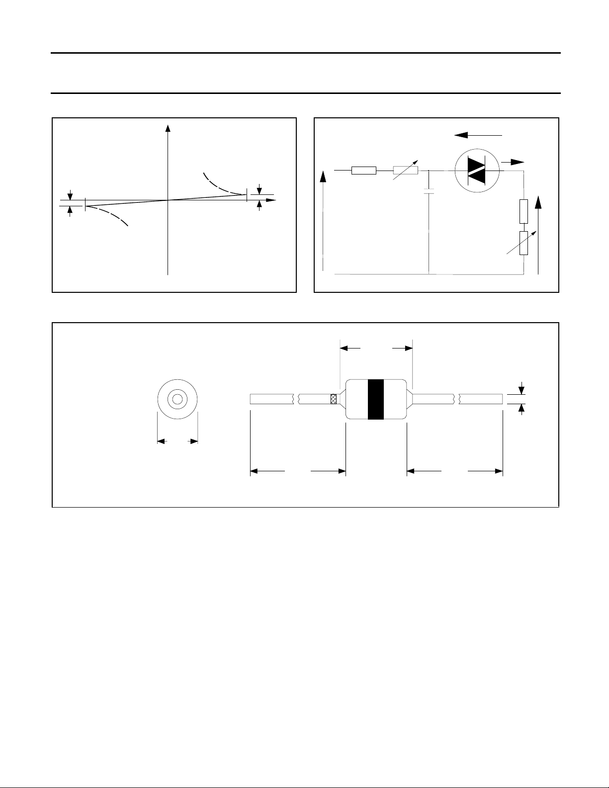
Fig.1. Current-voltage characteristics Fig.2. Test circuit for output voltage and risetime.
MECHANICAL DATA
Dimensions in mm
V(BO)I
I(BO)I
VBO
D.U.T.
10k
V
230 V, RMS, 50Hz
500k
100nF
Set load resistance
to 20 Ohms when
measuring output voltage
Adjust for Ip=0.5A
when measuring risetime
IT
10R
Vo
50R
4.5
max
0.56
max
1.95
max
24
min
24
min
Fig.3. SOD27.
February 1996 2 Rev 1.100
 Loading...