

Philips BLW98 Datasheet

DISCRETE SEMICONDUCTORS
DATA SH EET
BLW98
UHF linear power transistor
Product specification
August 1986

Philips Semiconductors Product specification
UHF linear power transistor BLW98
DESCRIPTION
N-P-N silicon planar epitaxial
transistor primarily intended for use in
linear u.h.f. amplifiers of TV
transposers and transmitters in band
FEATURES:
• diffused emitter ballasting resistors
for an optimum temperature profile;
• gold sandwich metallization
ensures excellent reliability.
IV-V, as well as for driver stages in
tube systems.
The transistor has a1⁄4" capstan
envelope with ceramic cap. All leads
are isolated from the stud.
QUICK REFERENCE DATA
R.F. performance in linear amplifier
MODE OF OPERATION f
vision
MHz
V
CE
V
I
C
mA
T
°C
h
(1)
d
im
P
dB
o sync
W
(1)
G
dB
p
class-A 860 25 850 70 −60 > 3,5 > 6,5
class-A 860 25 850 25 −60 typ. 4,4 typ. 7,0
Note
1. Three-tone test method (vision carrier −8 dB, sound carrier −7 dB, sideband signal−16 dB), zero dB corresponds to
peak sync level.
PIN CONFIGURATION
PINNING - SOT122A.
PIN DESCRIPTION
1 collector
2 emitter
Top view
4
31
2
MBK187
3 base
4 emitter
handbook, halfpage
Fig.1 Simplified outline. SOT122A.
PRODUCT SAFETY This device incorporates beryllium oxide, the dust of which is toxic. The device is entirely
safe provided that the BeO disc is not damaged.
August 1986 2
Philips Semiconductors Product specification
UHF linear power transistor BLW98
RATINGS
Limiting values in accordance with the Absolute Maximum System (IEC 134)
Collector-emitter voltage
(peak value); V
open base V
Emitter-base voltage (open collector) V
Collector current
d.c. I
(peak value); f > 1 MHz I
Total power dissipation at T
Storage temperature T
Operating junction temperature T
=0 V
BE
=70°CP
h
CESM
CEO
EBO
C
CM
tot
stg
j
max. 50 V
max. 27 V
max. 3,5 V
max. 2 A
max. 4 A
max. 21,5 W
−65 to +150 °C
max. 200 °C
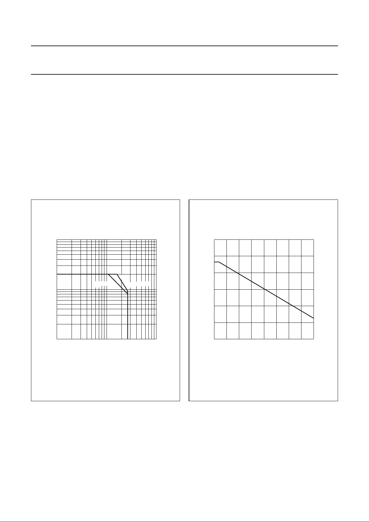
10
handbook, halfpage
I
C
(A)
(1)
T
= 70 °C Tmb = 25 °C
1
−1
10
11010
(1) Second breakdown limit (independent of temperature).
h
VCE (V)
Fig.2 D.C. SOAR.
MGP717
2
40
handbook, halfpage
P
tot
(W)
30
20
10
0
Fig.3 Power derating curve vs. temperature.
THERMAL RESISTANCE
(dissipation = 21,25 W; T
= 82,75 °C, Th=70°C)
mb
From junction to mounting base R
From mounting base to heatsink R
th j-mb
th mb-h
MGP718
50 100
Th (°C)
= 5,45 K/W
= 0,6 K/W
August 1986 3
Philips Semiconductors Product specification
UHF linear power transistor BLW98
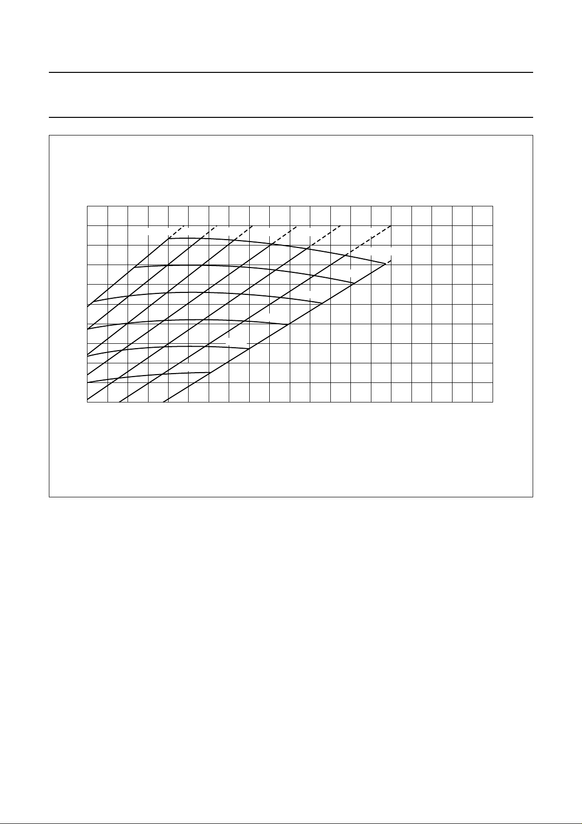
6.5
handbook, full pagewidth
R
th j-h
(K/W)
6
5.5
5
4.5
4
515 35
Th = 120 °C
100 °C
75 °C
80 °C
100 °C
60 °C 40 °C 20 °C
Tj = 200 °C
175 °C
150 °C
125 °C
25
0 °C
P
tot
MGP719
(W)
Fig.4 Maximum thermal resistance from junction to heatsink as a function of power dissipation, with heatsink
and junction temperature as parameters. (R
th mb-h
= 0,6 K/W.)
45
Example
Nominal class-A operation (without r.f. signal): V
Fig.4 shows: R
Typical device: R
T
T
th j-h
j
th j-h
j
max. 6,05 K/W
max. 200 °C
typ. 5,35 K/W
typ. 183 °C
= 25 V; IC= 850 mA; Th=70°C.
CE
August 1986 4
 Loading...