

Philips BLW97 Datasheet

DISCRETE SEMICONDUCTORS
DATA SH EET
BLW97
HF power transistor
Product specification
August 1986

Philips Semiconductors Product specification
HF power transistor BLW97
DESCRIPTION
N-P-N silicon planar epitaxial
transistor designed for use in class-A,
AB and B operated high-power
industrial and military transmitting
equipment in the h.f. band.
The transistor offers excellent
performance as a linear amplifier in
s.s.b. applications. It is resistance
stabilized and is made to withstand
QUICK REFERENCE DATA
R.F. performance up to T
MODE OF OPERATION V
= 25 °C
h
CE
V
s.s.b.
(class-AB)
28 0,1 1,6−28 175 (PEP) > 11,5 > 40 <−30 < −30
PIN CONFIGURATION
handbook, halfpage
43
severe load-mismatch conditions. All
leads are isolated from the flange.
The transistors are supplied in
matched h
I
C(ZS)
A
groups.
FE
MHz
f
P
L
W
G
dB
p
η
dt
%
d
dB
PINNING - SOT121B.
PIN DESCRIPTION
1 collector
2 emitter
3 base
4 emitter
3
d
5
dB
21
MLA876
Fig.1 Simplified outline. SOT121B.
PRODUCT SAFETY This device incorporates beryllium oxide, the dust of which is toxic. The device is entirely
safe provided that the BeO disc is not damaged.
August 1986 2
Philips Semiconductors Product specification
HF power transistor BLW97
RATINGS
Limiting values in accordance with the Absolute Maximum System (IEC 134)
Collector-emitter voltage (peak value)
V
= 0 V
BE
open base V
Emitter-base voltage (open collector) V
CESM
CEO
EBO
Collector current
average I
peak value; f > 1 MHz I
Total d.c. power dissipation at T
=25°CP
h
C(AV)
CM
tot(d.c.)
R.F. power dissipation
f > 1 MHz; Th= 25°CP
Storage temperature T
Operating junction temperature T
tot(rf)
stg
j
max. 65 V
max. 33 V
max. 4 V
max. 15 A
max. 50 A
max. 190 W
max. 230 W
−65 to + 150 °C
max. 200 °C
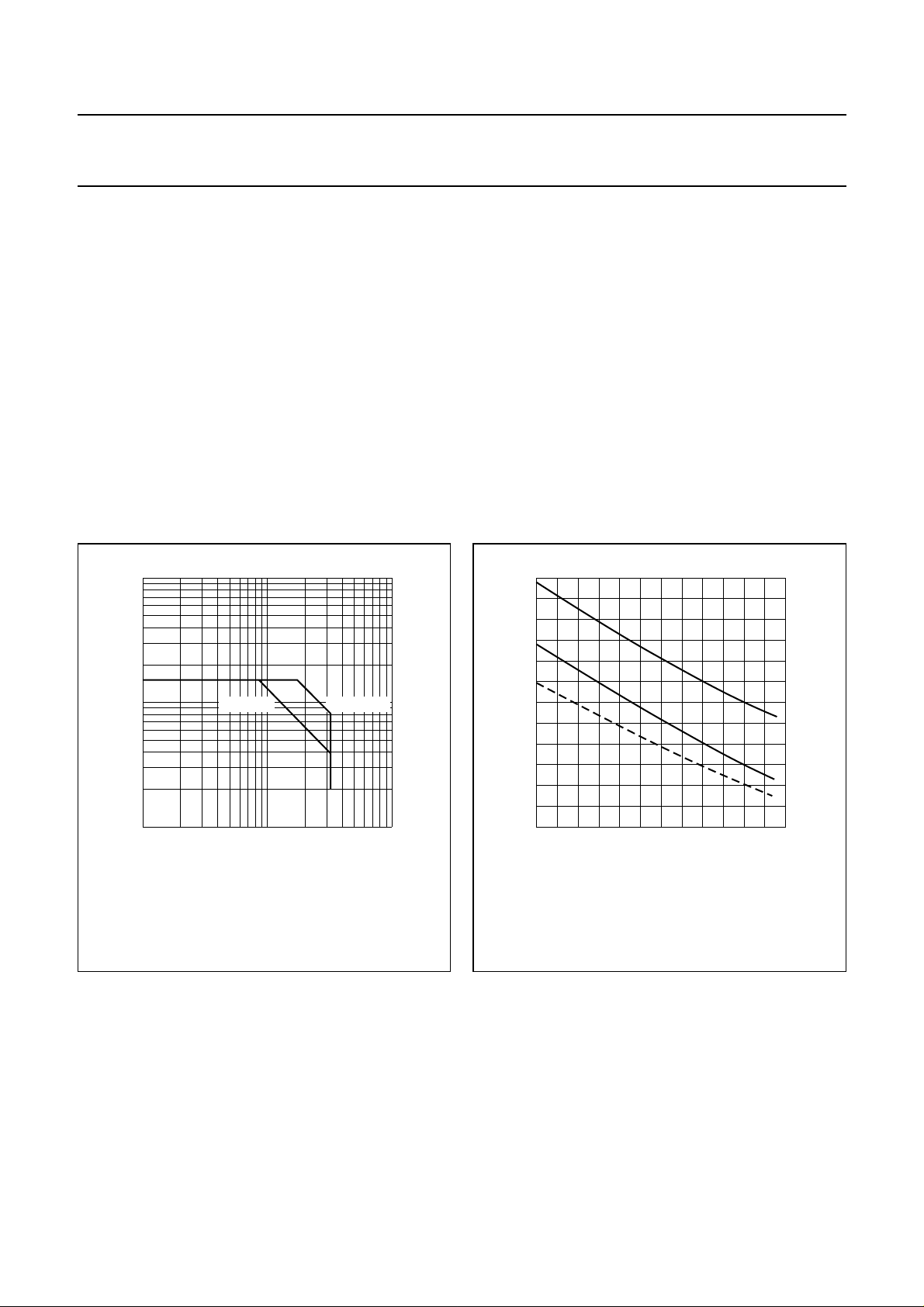
2
10
handbook, halfpage
I
C
(A)
10
1
11010
Th = 70 °C Tmb = 25 °C
VCE (V)
Fig.2 D.C. SOAR.
MGP703
2
350
handbook, halfpage
P
tot
(W)
250
150
50
I Continuous d.c. operation
II Continuous r.f. operation (f > 1 Mhz).
III Short-time operation during mismatch; (f > 1 MHz).
Fig.3 Power/temperature derating curves.
THERMAL RESISTANCE
(dissipation = 120 W; T
=25°C i.e. Tmb=49°C)
h
From junction to mounting base
(d.c. dissipation) R
From junction to mounting base
(r.f. dissipation) R
From mounting base to heatsink R
MGP704
ΙΙΙ
ΙΙ
Ι
0 40 120
th j-mb(dc)
th j-mb(rf)
th mb-h
= 0,63 K/W
= 0,48 K/W
= 0,20 K/W
80
Th (°C)
August 1986 3

Philips Semiconductors Product specification
HF power transistor BLW97
CHARACTERISTICS
T
=25°C unless otherwise specified
j
Collector-emitter breakdown voltage
V
= 0; IC= 50 mA V
BE
= 100 mA; open base V
I
C
Emitter-base breakdown voltage
I
= 20 mA; open collector V
E
Collector cut-off current
VCE= 33 V; VBE=0 I
Second breakdown energy; L = 25 mH; f = 50 Hz
open base E
R
=10Ω E
BE
D.C. current gain
I
= 10 A; VCE=5 V h
C
D.C. current gain ratio of matched devices
(1)
(1)
IC= 10 A; VCE=5 V h
Collector-emitter saturation voltage
(1)
IC= 25 A; IB=5 A V
Transition frequency at f = 100 MHz
(2)
−IE= 10 A; VCB= 28 V f
−I
= 20 A; VCB= 28 V f
E
Collector capacitance at f = 1 MHz
IE=ie=0;VCB= 28 V C
Feedback capacitance at f = 1 MHz
IC= 0; VCE= 28 V C
Collector-flange capacitance C
(BR)CES
(BR)CEO
(BR)EBO
CES
SBO
SBR
FE
FE1/hFE2
CEsat
T
T
c
re
cf
> 65 V
> 33 V
> 4V
< 20 mA
> 20 mJ
> 20 mJ
typ. 30
15 to 50
< 1,2
typ. 2,4 V
typ. 230 MHz
typ. 235 MHz
typ. 380 pF
typ. 235 pF
typ. 4,5 pF
Notes
1. Measured under pulse conditions: t
= 500 µs.
p
2. Measured under pulse conditions: tp= 300 µs; δ = 0,02.
August 1986 4
 Loading...