

Philips BLW90 Datasheet

DISCRETE SEMICONDUCTORS
DATA SH EET
BLW90
UHF power transistor
Product specification
August 1986

Philips Semiconductors Product specification
UHF power transistor BLW90
1
DESCRIPTION
N-P-N silicon planar epitaxial
transistor suitable for transmitting
applications in class-A, B or C in the
u.h.f. and v.h.f. range for a nominal
supply voltage of 28 V. The transistor
is resistance stabilized and is
guaranteed to withstand infinite
VSWR at rated output power. High
reliability is ensured by a gold
sandwich metallization.
QUICK REFERENCE DATA
R.F. performance up to T
= 25 °C in an unneutralized common-emitter class-B circuit
h
The transistor is housed in a
capstan envelope with a ceramic cap.
All leads are isolated from the stud.
⁄4"
MODE OF OPERATION V
c.w. 28 470 4 > 11 > 55
PIN CONFIGURATION
handbook, halfpage
Top view
Fig.1 Simplified outline. SOT122A.
CE
V
f
MHz
P
W
L
G
p
dB
η
%
PINNING - SOT122A.
PIN DESCRIPTION
1 collector
2 emitter
4
31
2
MBK187
3 base
4 emitter
PRODUCT SAFETY This device incorporates beryllium oxide, the dust of which is toxic. The device is entirely
safe provided that the BeO disc is not damaged.
August 1986 2
Philips Semiconductors Product specification
UHF power transistor BLW90
RATINGS
Limiting values in accordance with the Absolute Maximum System (IEC 134)
Collector-emitter voltage
(peak value); V
open base V
Emitter-base voltage (open collector) V
Collector current
d.c. or average I
(peak value); f > 1 MHz I
Total power dissipation (d.c. and r.f.) up to T
Storage temperature T
Operating junction temperature T
= 0 V
BE
= 25 °CP
mb
CESM
CEO
EBO
C;IC(AV)
CM
tot
stg
j
max. 60 V
max. 30 V
max. 4 V
max. 0,62 A
max. 2,0 A
max. 18,6 W
−65 to + 150 °C
max. 200 °C
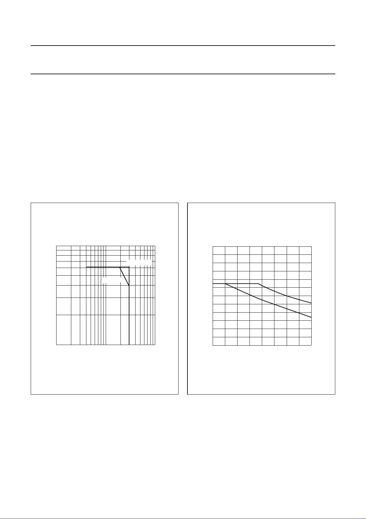
handbook, halfpage
1
I
C
(A)
1
−
10
11010
Th = 70 °C
VCE (V)
Fig.2 D.C. SOAR.
MGP660
T
= 25 °C
mb
2
30
handbook, halfpage
P
tot
(W)
20
10
I Continuous d.c. and r.f. operation
II Short-time operation during mismatch
Fig.3 Power derating curves vs. temperature.
THERMAL RESISTANCE
(dissipation = 6 W; T
= 73,6 °C, i.e. Th= 70 °C)
mb
From junction to mounting base
(d.c. and r.f. dissipation) R
From mounting base to heatsink R
MGP661
ΙΙ
Ι
0
0 100
th j-mb
th mb-h
50
Th (°C)
= 9,0 K/W
= 0,6 K/W
August 1986 3

Philips Semiconductors Product specification
UHF power transistor BLW90
CHARACTERISTICS
T
=25°C
j
Collector-emitter breakdown voltage
V
= 0; IC= 4 mA V
BE
(BR)CES
Collector-emitter breakdown voltage
open base; IC= 20 mA V
(BR)CEO
Emitter-base breakdown voltage
open collector; IE= 2 mA V
(BR)EBO
Collector cut-off current
VBE= 0; VCE= 30 V I
CES
Second breakdown energy; L = 25 mH; f = 50 Hz
open base E
R
=10Ω E
BE
D.C. current gain
I
= 0,3 A; VCE=5 V 10 to 100
C
Collector-emitter saturation voltage
(1)
(1)
IC= 1,0 A; IB= 0,2 A V
Transition frequency at f = 500 MHz
(1)
−IE= 0,3 A; VCB= 28 V f
−I
= 1,0 A; VCB= 28 V f
E
h
T
T
SBO
SBR
FE
CEsat
Collector capacitance at f = 1 MHz
I
=0;VCB= 28 V C
E=Ie
c
Feedback capacitance at f = 1 MHz
IC= 20 mA; VCE= 28 V C
Collector-stud capacitance C
re
cs
> 60 V
> 30 V
> 4V
< 2mA
> 1mJ
> 1mJ
typ. 40
typ. 0,9 V
typ. 1,2 GHz
typ. 0,9 GHz
typ. 8,4 pF
typ. 3,6 pF
typ. 1,2 pF
Note
1. Measured under pulse conditions: t
≤ 200 µs; δ≤0,02.
p
August 1986 4
 Loading...